FANUC Series 0i-MODEL D, Series 0i Mate-MODEL D. OPERATOR'S MANUAL - page 33

A.PARAMETERS
APPENDIX
B-64304EN/02
A.2 DATA TYPE
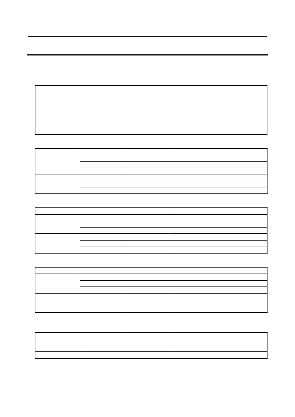
Parameters are classified by data type as follows:
Data type
Valid data range
Remarks
Bit
Bit machine group
Bit path
0 or 1
Bit axis
Bit spindle
Byte
Byte machine group
-128 to 127
Some parameters handle these types of
Byte path
0 to 255
data as unsigned data.
Byte axis
Byte spindle
Word
Word machine group
-32768 to 32767
Some parameters handle these types of
Word path
0 to 65535
data as unsigned data.
Word axis
Word spindle
2-word
2-word machine group
Some parameters handle these types of
2-word path
0 to ±999999999
data as unsigned data.
2-word axis
2-word spindle
Real
Real machine group
See the Standard Parameter
Real path
Setting Tables.
Real axis
Real spindle
NOTE
1 Each of the parameters of the bit, bit machine group, bit path, bit axis, and bit
spindle types consists of 8 bits for one data number (parameters with eight
different meanings).
2 For machine group types, parameters corresponding to the maximum number of
machine groups are present, so that independent data can be set for each
machine group.
3 For path types, parameters corresponding to the maximum number of paths are
present, so that independent data can be set for each path.
4 For axis types, parameters corresponding to the maximum number of control
axes are present, so that independent data can be set for each control axis.
5 For spindle types, parameters corresponding to the maximum number of
spindles are present, so that independent data can be set for each spindle axis.
6 The valid data range for each data type indicates a general range. The range
varies according to the parameters. For the valid data range of a specific
parameter, see the explanation of the parameter.
- 936 -
B-64304EN/02
APPENDIX
A.PARAMETERS
A.3 STANDARD PARAMETER SETTING TABLES
This section defines the standard minimum data units and valid data ranges of the CNC parameters of the
real type, real machine group type, real path type, real axis type, and real spindle type. The data type and
unit of data of each parameter conform to the specifications of each function.
NOTE
1 Values are rounded up or down to the nearest multiples of the minimum data
unit.
2 A valid data range means data input limits, and may differ from values
representing actual performance.
3 For information on the ranges of commands to the CNC, refer to Appendix D,
"Range of Command Value."
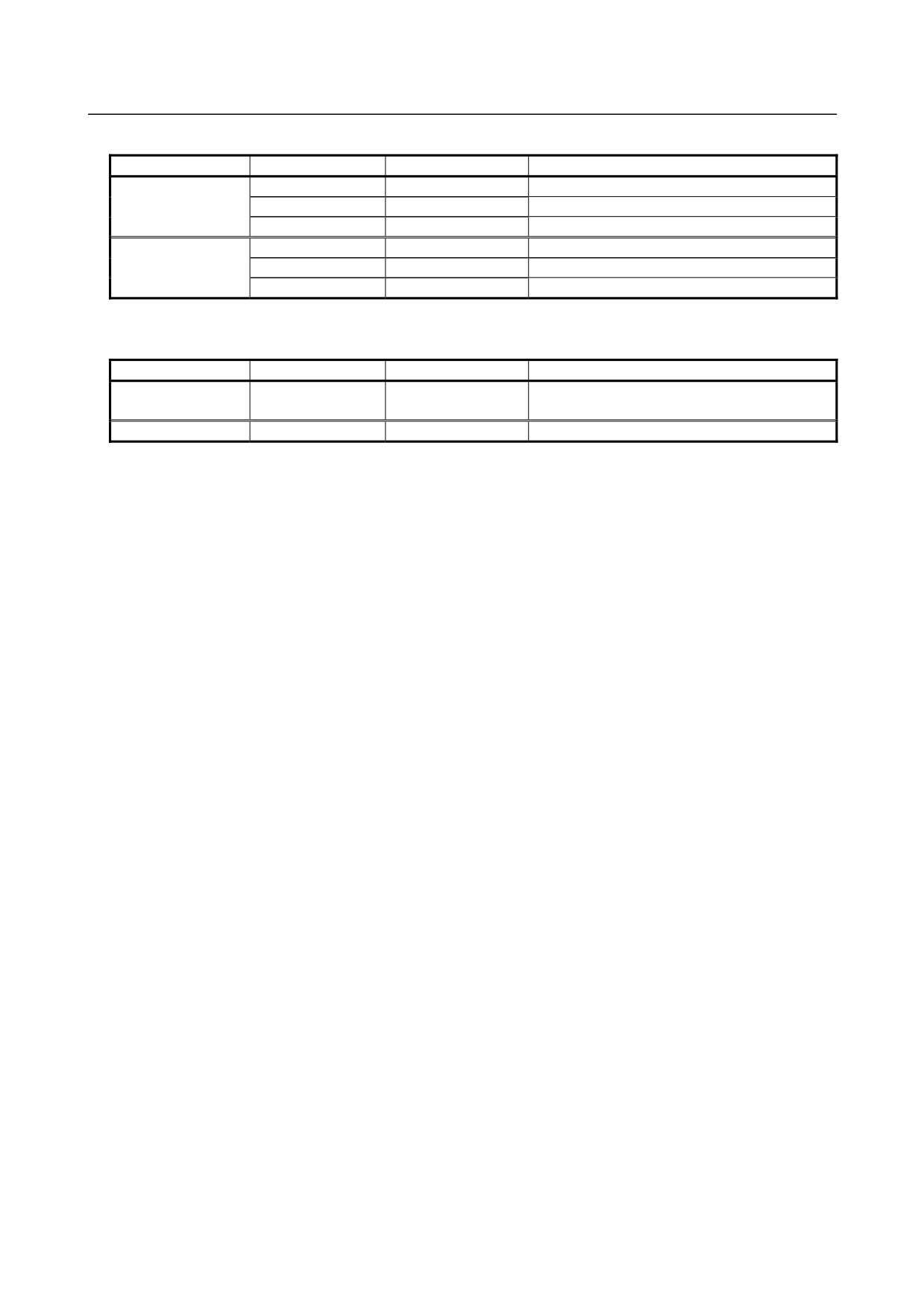
(A) Length and angle parameters (type 1)
Unit of data
Increment system
Minimum data unit
Valid data range
IS-A
0.01
-999999.99
to +999999.99
mm
IS-B
0.001
-999999.999
to +999999.999
deg.
IS-C
0.0001
-99999.9999
to
+99999.9999
IS-A
0.001
-99999.999
to
+99999.999
inch
IS-B
0.0001
-99999.9999
to
+99999.9999
IS-C
0.00001
-9999.99999
to
+9999.99999
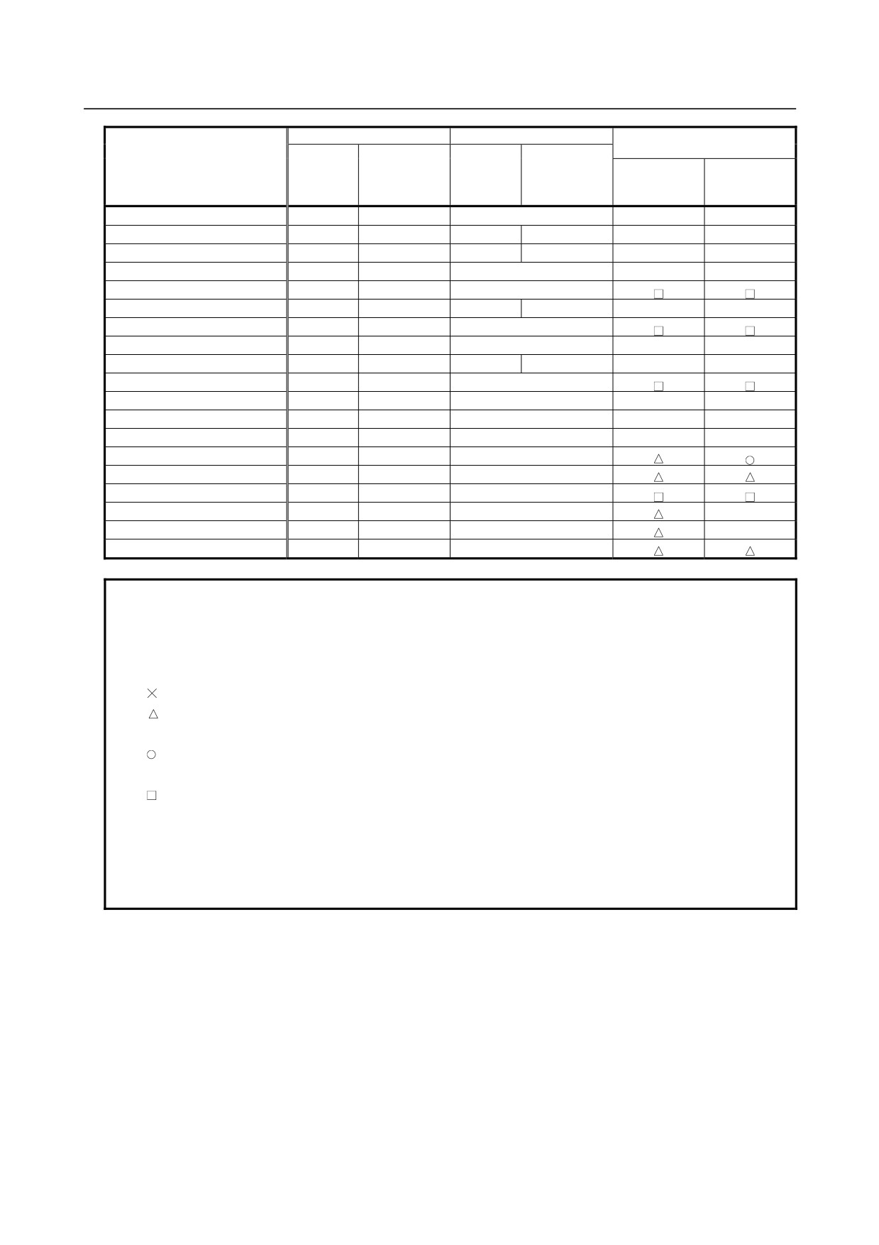
(B) Length and angle parameters (type 2)
Unit of data
Increment system
Minimum data unit
Valid data range
IS-A
0.01
0.00
to +999999.99
mm
IS-B
0.001
0.000
to +999999.999
deg.
IS-C
0.0001
0.0000
to
+99999.9999
IS-A
0.001
0.000
to
+99999.999
inch
IS-B
0.0001
0.0000
to
+99999.9999
IS-C
0.00001
0.00000
to
+9999.99999
(C) Velocity and angular velocity parameters
Unit of data
Increment system
Minimum data unit
Valid data range
IS-A
0.01
0.0 to
+999000.00
mm/min
IS-B
0.001
0.0 to
+999000.000
degree/min
IS-C
0.0001
0.0 to
+99999.9999
IS-A
0.001
0.0 to
+96000.000
inch/min
IS-B
0.0001
0.0 to
+9600.0000
IS-C
0.00001
0.0 to
+4000.00000
If bit 7 (IESP) of parameter No. 1013 is set to 1, the valid data ranges for IS-C are extended as follows:
Unit of data
Increment system
Minimum data unit
Valid data range
mm/min
IS-C
0.001
0.000 to +999000.000
degree/min
inch/min
IS-C
0.0001
0.0000 to +9600.0000
- 937 -
A.PARAMETERS
APPENDIX
B-64304EN/02
(D)Acceleration and angular acceleration parameters
Unit of data
Increment system
Minimum data unit
Valid data range
IS-A
0.01
0.00
to +999999.99
mm/sec2
IS-B
0.001
0.000
to +999999.999
deg./sec2
IS-C
0.0001
0.0000
to
+99999.9999
IS-A
0.001
0.000
to
+99999.999
inch/sec
2
IS-B
0.0001
0.0000
to
+99999.9999
IS-C
0.00001
0.00000
to
+9999.99999
If bit 7 (IESP) of parameter No. 1013 is set to 1, the valid data ranges for IS-C are extended as follows:
Unit of data
Increment system
Minimum data unit
Valid data range
mm/min
IS-C
0.001
0.000 to +999999.999
degree/min
inch/min
IS-C
0.0001
0.0000 to +99999.9999
- 938 -

B-64304EN/02
APPENDIX
B.PROGRAM CODE LIST
B PROGRAM CODE LIST
ISO code
EIA code
Custom macro
Character name
Code
Code
without
Character
Character
with custom
(hexadecimal)
(hexadecimal)
custom
macro
macro
Number
0
0
30
0
20
Number
1
1
B1
1
01
Number
2
2
B2
2
02
Number
3
3
33
3
13
Number
4
4
B4
4
04
Number
5
5
35
5
15
Number
6
6
36
6
16
Number
7
7
B7
7
07
Number
8
8
B8
8
08
Number
9
9
39
9
19
Address A
A
41
a
61
Address B
B
42
b
62
Address C
C
C3
c
73
Address D
D
44
d
64
Address E
E
C5
e
75
Address F
F
C6
f
76
Address G
G
47
g
67
Address H
H
48
h
68
Address I
I
C9
i
79
Address J
J
CA
j
51
Address K
K
4B
k
52
Address L
L
CC
l
43
Address M
M
4D
m
54
Address N
N
4E
n
45
Address O
O
CF
o
46
Address P
P
50
p
57
Address Q
Q
D1
q
58
Address R
R
D2
r
49
Address S
S
53
s
32
Address T
T
D4
t
23
Address U
U
55
u
34
Address V
V
56
v
25
Address W
W
D7
w
26
Address X
X
D8
x
37
Address Y
Y
59
y
38
Address Z
Z
5A
z
29
Delete
DEL
FF
Del
7F
Back space
BS
88
BS
2A
Tabulator
HT
09
Tab
2E
End of block
LF or NL
0A
CR or EOB
80
Carriage return
CR
8D
Space
SP
A0
SP
10
Absolute rewind stop
%
A5
ER
0B
Control out (start of comment)
(
28
(2-4-5)
1A
Control in (end of comment)
)
A9
(2-4-7)
4A
Plus sign
+
2B
+
70
Minus sign
-
2D
-
40
- 939 -
B.PROGRAM CODE LIST
APPENDIX
B-64304EN/02
ISO code
EIA code
Custom macro
Character name
Code
Code
without
Character
Character
with custom
(hexadecimal)
(hexadecimal)
custom
macro
macro
Colon (address O)
:
3A
Optional block skip
/
AF
/
31
Period (decimal point)
2E
6B
Sharp
#
A3
Parameter (No.6012)
Dollar sign
$
24
Ampersand
&
A6
&
0E
Apostrophe
’
27
Asterisk
AA
Parameter (No.6010)
Comma
,
AC
,
3B
Semicolon
;
FB
Left angle bracket
<
2C
Equal sign
=
BD
Parameter (No.6011)
Right angle bracket
>
BE
Question mark
?
3F
Commercial at mark
@
C0
Quotation mark
“
22
Left square bracket
[
DB
Parameter (No.6013)
Right square bracket
]
DD
Parameter (No.6014)
Underscore
_
6F
Parameter (No.6018)
NOTE
1 The symbols used in the "Custom macro" column have the following meanings.
(Space) : The character will be registered in memory and has a specific meaning.
It is used incorrectly in a statement other than a comment, an alarm
occurs.
:
The character will not be registered in memory and will be ignored.
:
The character will be registered in memory, but will be ignored during
program execution.
:
The character will be registered in memory. If it is used in a statement
other than a comment, an alarm occurs.
:
If it is used in a statement other than a comment, the character will not
be registered in memory. If it is used in a comment, it will be
registered in memory.
2 Codes not in this table are ignored if their parity is correct.
3 Codes with incorrect parity cause the TH alarm. But they are ignored without
generating the TH alarm when they are in the comment section.
- 940 -
C.LIST OF FUNCTIONS AND
B-64304EN/02
APPENDIX
PROGRAM FORMAT
C LIST OF FUNCTIONS AND PROGRAM
FORMAT
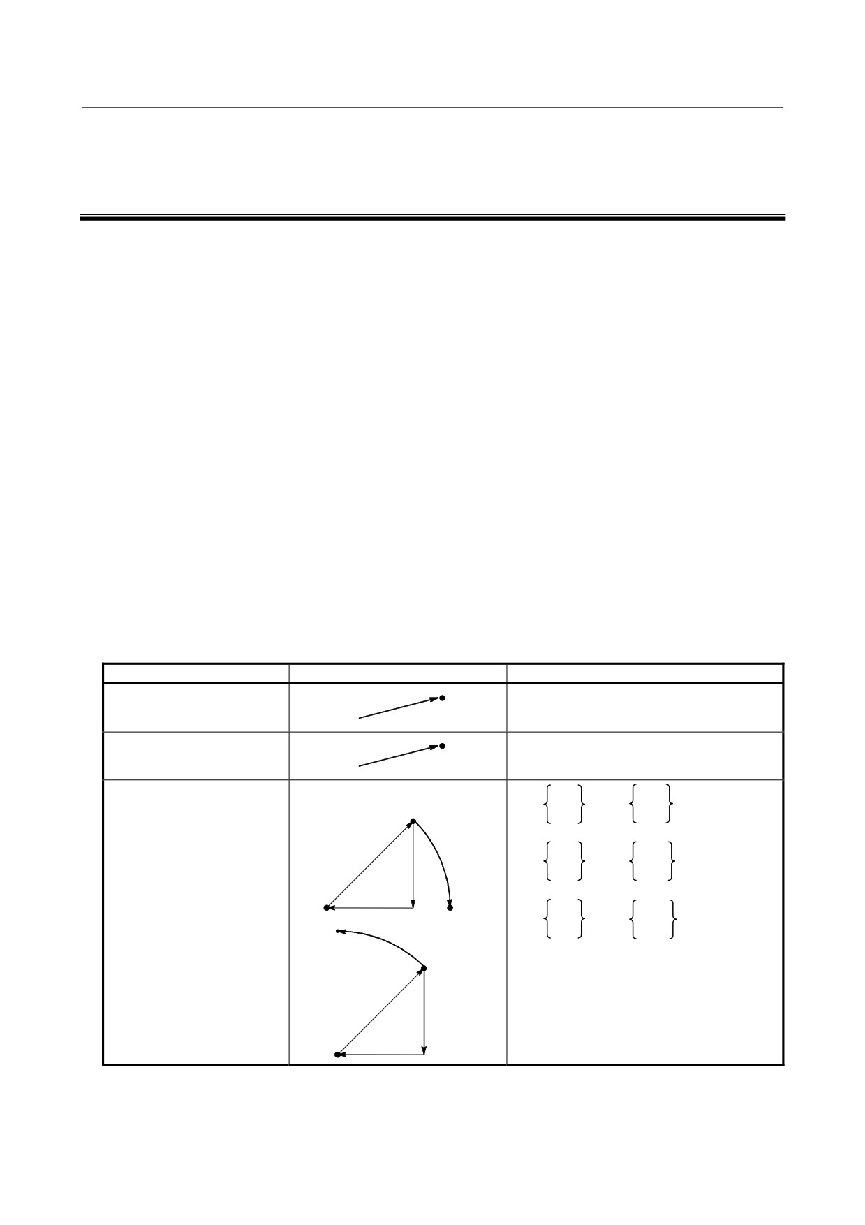
With some functions, the format used for specification on the M series differs from the format used for
specification on the T series. Some functions are supported only for either M series or T series.
Some functions cannot be added as options depending on the model.
For details of command formats, see the relevant sections or subsections.
In the list, the following symbols are used:
• For M series
x : 1st basic axis (X),
y : 2nd basic axis (Y),
z : 3rd basic axis (Z)
• For T series
x : 1st basic axis (X),
z : 2nd basic axis (Z),
coded using G code system A
IP_
: presents a combination of arbitrary axis addresses using X, Y, Z, A, B, C, U, V, and W (such as X_
Y_ Z_A_).
α
: One of the arbitrary addresses
β
: One of the arbitrary addresses
Xp
: X-axis or axis parallel to the X-axis
Yp
: Y-axis or axis parallel to the Y-axis
Zp
: Z-axis or axis parallel to the Z-axis
Functions
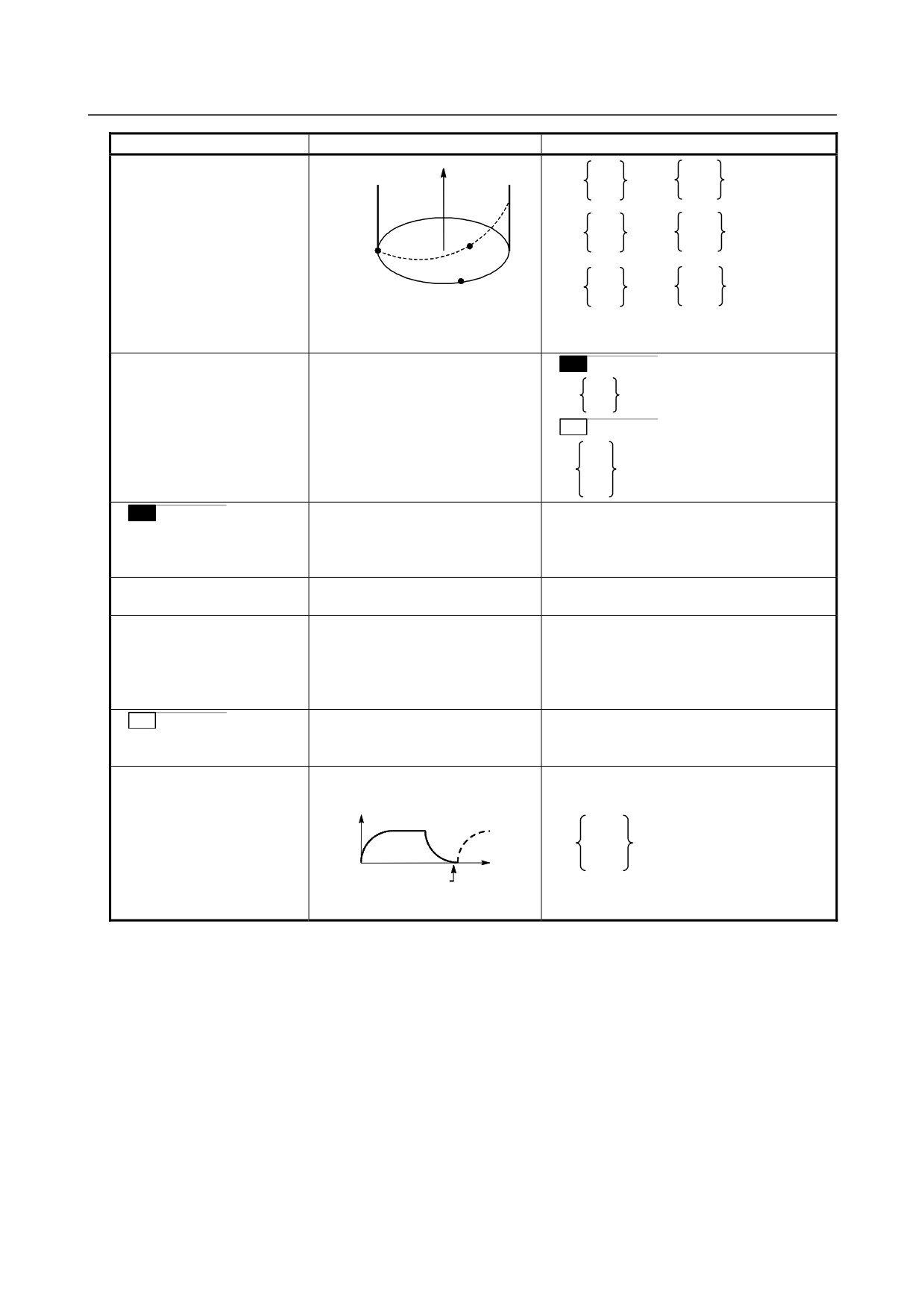
Illustration
Program format
Positioning
IP
G00 IP_ ;
(G00)
Start point
Linear interpolation
IP
G01 IP_ F_;
(G01)
Start point
Circular interpolation
G02
R_
(G02, G03)
Start point
G17
X_ Y_
F_ ;
G03
I_ J_
G02
R_
R
G02
G18
X_ Z_
F_ ;
J
G03
I_ K_
I
G02
R_
(x, y)
G19
Y_ Z_
F_ ;
G03
G03
J_ K_
(x, y)
R
J
I
Start point
- 941 -
C. LIST OF FUNCTIONS AND
PROGRAM FORMAT
APPENDIX
B-64304EN/02
Functions
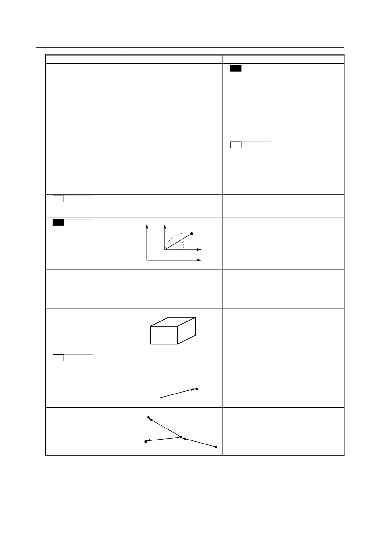
Illustration
Program format
Helical interpolation
z
R_
G02
G17
X_ Y_
α_ F_ ;
(G02, G03)
I_ J_
G03
G02
R_
G18
X_ Z_
α_ F_ ;
G03
I_ K_
Start
(xyz)
point
G02
R_
G19
Y_ Z_
α_ F_ ;
(x, y)
G03
J_ K_
In case of G03 on X-Y plane
α: Arbitrary address except the circular
interpolation axis
Dwell
M
(G04)
X_
G04
;
P_
T
X_
G04
U_
;
P_
M
G05.1 Q1 ; AI advanced preview control /
AI advanced preview control /
AI contour control mode on
AI contour control
G05.1 Q0 ; AI advanced preview control /
(G05.1)
AI contour control mode off
HRV3 control
G05.4 Q1 ; HRV3 control mode on
(G05.4)
G05.4 Q0 ; HRV3 control mode off
Cylindrical interpolation
G07 IP_ r_;
Cylindrical interpolation
(G07.1)
mode
r : Cylinder radius
G07 IP 0; Cylindrical interpolation mode
cancel
T
G08 P1 ; AI contour control mode on
Advanced preview control
G08 P0 ; AI contour control mode off
(G08)
Exact stop
(G09)
Speed
G01
G09
G02
IP_ ;
Time
G03
In-position check
- 942 -
C.LIST OF FUNCTIONS AND
B-64304EN/02
APPENDIX
PROGRAM FORMAT
Functions
Illustration
Program format
Programmable data input
M
(G10)
Tool compensation memory A
G10 L01 P_ R_ ;
Tool compensation memory C
G10 L10 P_ R_ ; (Geometry offset
amount/H)
G10 L11 P_ R_ ; (Wear offset amount/H)
G10 L12 P_ R_ ; (Geometry offset
amount/D)
G10 L13 P_ R_ ; (Wear offset amount/D)
T
Geometry offset amount
G10 P_ X_ Z_ R_ Q_ ;
P = 10000 + Geometry offset number
Wear offset amount
G10 P_ X_ Z_ C_ Q_ ;
P = Wear offset number
T
G12.1 ; Polar coordinate interpolation mode
Polar coordinate interpolation
on
(G12.1, G13.1)
G13.1 ; Polar coordinate interpolation cancel
M
Local coordinate system
G17 G16 Xp_ Yp_ . . . ;
Polar coordinate command
Yp
G18 G16 Zp_ Xp_ . . . ;
Xp
(G15, G16)
G19 G16 Yp_ Zp_ . . . ;
Yp
G15 ; Cancel
Xp
Workpiece coordinate system
Plane selection
G17 ; Xp Yp-plane selection
(G17, G18, G19)
G18 ; Zp Xp-plane selection
G19 ; Yp Zp-plane selection
Inch/metric conversion
Inch input G20 ;
(G20, G21)
Metric input G21 ;
Stored stroke check
(XYZ)
(G22, 23)
G22 X_ Y_ Z_ I_ J_ K_ ;
Stored stroke check on
G23 ;
Stored stroke check off
(IJK)
T
G26 P_ Q_ R_ I_ ; Spindle speed fluctuation
Spindle speed fluctuation
detection enabled
detection
G25 ;
Spindle speed fluctuation
(G25, G26)
detection disabled
Reference position return
IP
G27 IP_ ;
check
Start point
(G27)
Reference position return
Reference position (G28)
G28 IP_ ; Reference position return
(G28)
Intermediate point
2nd/3rd/4th Reference
G30 P2 IP_ ;
2nd reference position return
position return
IP
G30 P3 IP_ ;
3rd reference position return
Start point
(G30)
G30 P4 IP_ ;
4th reference position return
2nd/3rd/4th reference position(G30)
P2 can be omitted.
- 943 -
C. LIST OF FUNCTIONS AND
PROGRAM FORMAT
APPENDIX
B-64304EN/02
Functions
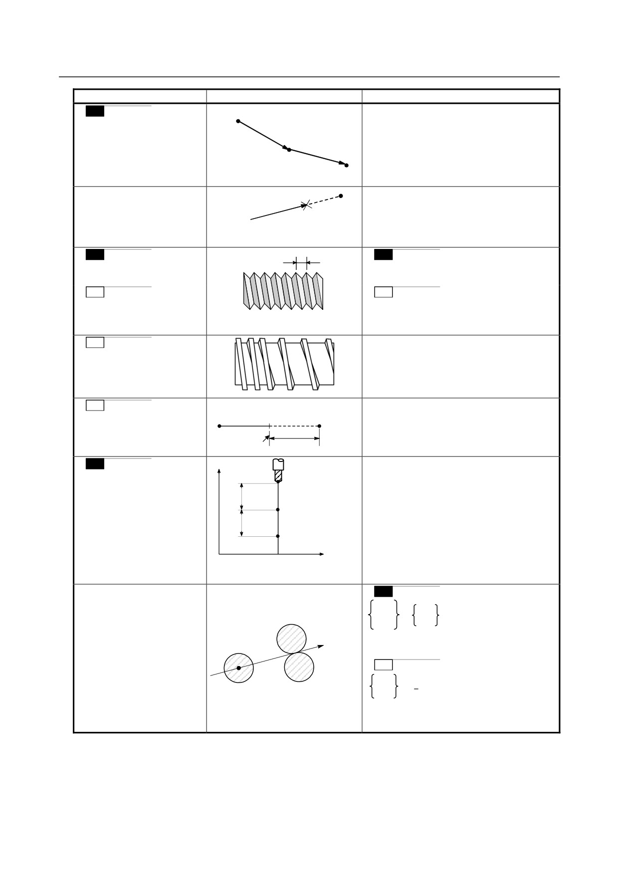
Illustration
Program format
M
Reference position
G29 IP_ ;
Movement from reference
position
(G29)
IP
Intermediate point
Skip function
IP
G31 IP_ F_ ;
(G31)
Start point
Skip signal
M
F
M
Threading
G33 IP_ F_ ;
(G33)
F : Lead
T
T
Threading
Equal lead threading
(G32)
G32 IP_ F_ ;
F : Lead
T
G34 IP_ F_ K_ ;
Variable lead thread cutting
F : Lead at the start position in the longitudinal
(G34)
direction
K : Lead increment/decrement per spindle
rotation
T
Measurement
position arrivalMeasurement
position
Automatic tool offset
Start position signal
G36 X_ ;
(G36,G37)
Programmed
G37 Z_ ;
position
Compensation
(X_ or _)
value
M
Z
G92 IP_ ; Workpiece coordinate system
Automatic tool length
setting
measurement
A (Start point)
Rapid
Measurement position is
(This can also be set with G54 to
(G37)
traverse
commanded with G37
B (Deceleration position)
G59)
Measurement
H○○ ; Offset number specified for tool
feedrate
C (Measurement position)
length compensation
The tool stops when the
approach end signal goes on.
G90 G37 IP_ ; Absolute programming
X
0
IP_ : Measurement position on X_, Y_, Z_,
Compensation value = (Current compensation value) +
[(Coordinates of the point at which the tool is stopped) -
or 4th axis
(Coordinates of the programmed measurement position)]
Tool radius/tool nose radius
M
compensation
G17
G41
(G39, G40 to G42)
G18
D_ ;
G42
G41
G19
D : Tool compensation number
G40 : Cancel
T
G42
G41
IP
;
G40
G42
G40 : Cancel
- 944 -
C.LIST OF FUNCTIONS AND
B-64304EN/02
APPENDIX
PROGRAM FORMAT
Functions
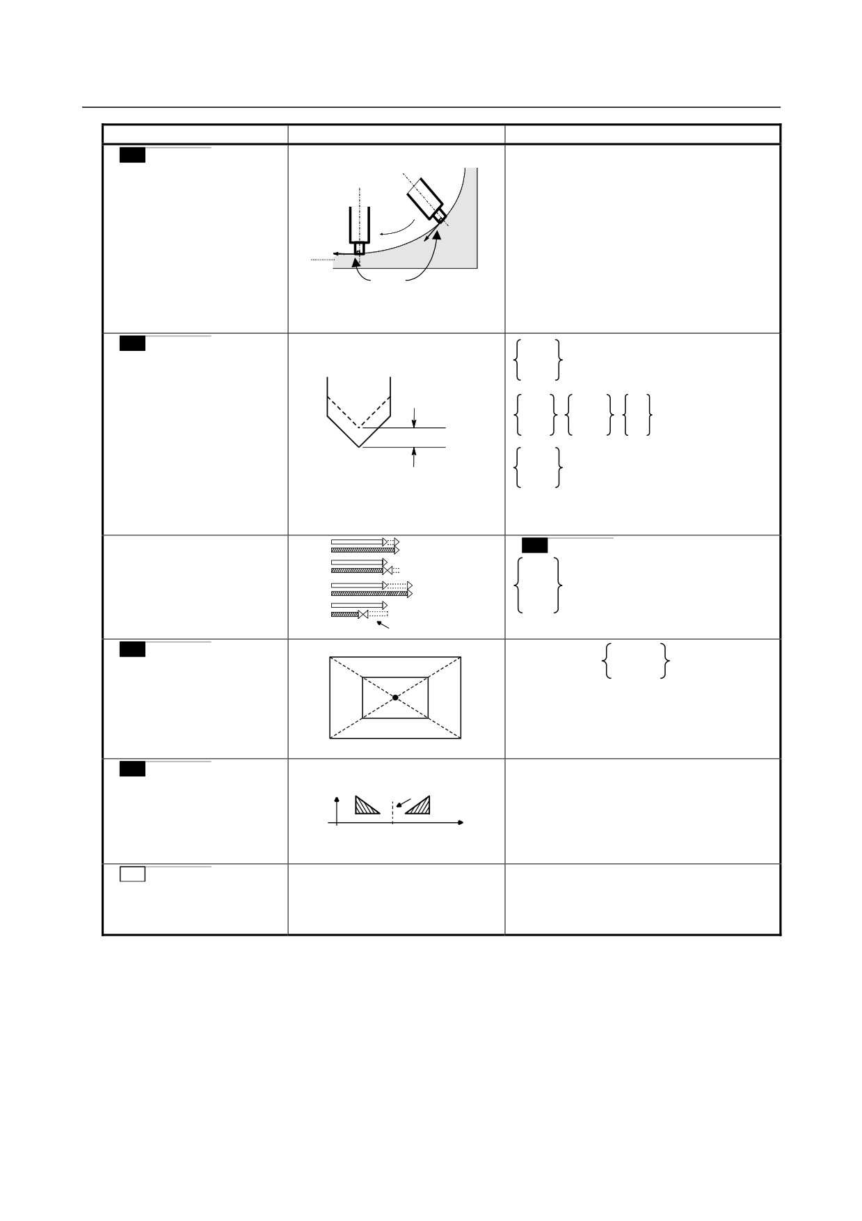
Illustration
Program format
M
Programmed
G41.1 ; Normal direction control on : right
Normal direction control
C-axis
path
G42.1 ; Normal direction control on : left
C-axis
(G40.1, G41.1, G42.1)
Tool
G40.1 ; Normal direction control cancel
Tool
Normal direction (in
which the tool moves)
M
G43
Tool length compensation
Z_ H_ ;
G44
(G43, G44, G49)
Compensation
G17
G43
Z
G18
Y
H_ ;
G19
G44
X
Z
G43
IP_
H_ ;
G44
H : Tool compensation number
G49 : Cancel
Tool offset
G 45
Increase
M
(G45 to G48)
IP
G 46
Decrease
G45
G46
Double increase
IP_ D_ ;
G 47
G47
G48
G 48
IP
Double decrease
Offset amount
D : Tool offset number
M
P4
P3
G51 X_ Y_ Z_
P_
;
Scaling
P4'
P3'
I_ J_ K_
(G50, G51)
IP
P, I, J, K : Scaling magnification
X, Y, Z : Control position of scaling
P1'
P2'
G50 : Cancel
P1
P2
M
G51.1 IP_ ; Setting
Programmable mirror image
Mirror
IP_: Command for the symmetric axis of the
(G50.1, G51.1)
mirror image
G50.1 IP_ ; Cancel
IP
IP_: Any command for the symmetric axis of
the mirror image
T
G51.2 (G251) P_ Q_ ; Polygon turning on
Polygon turning
P_ Q_ : Rotation ratio between the spindle
(G50.2, G51.2)
and rotation axis
(G250, G251)
G50.2 (G250) ; Polygon turning cancel
- 945 -
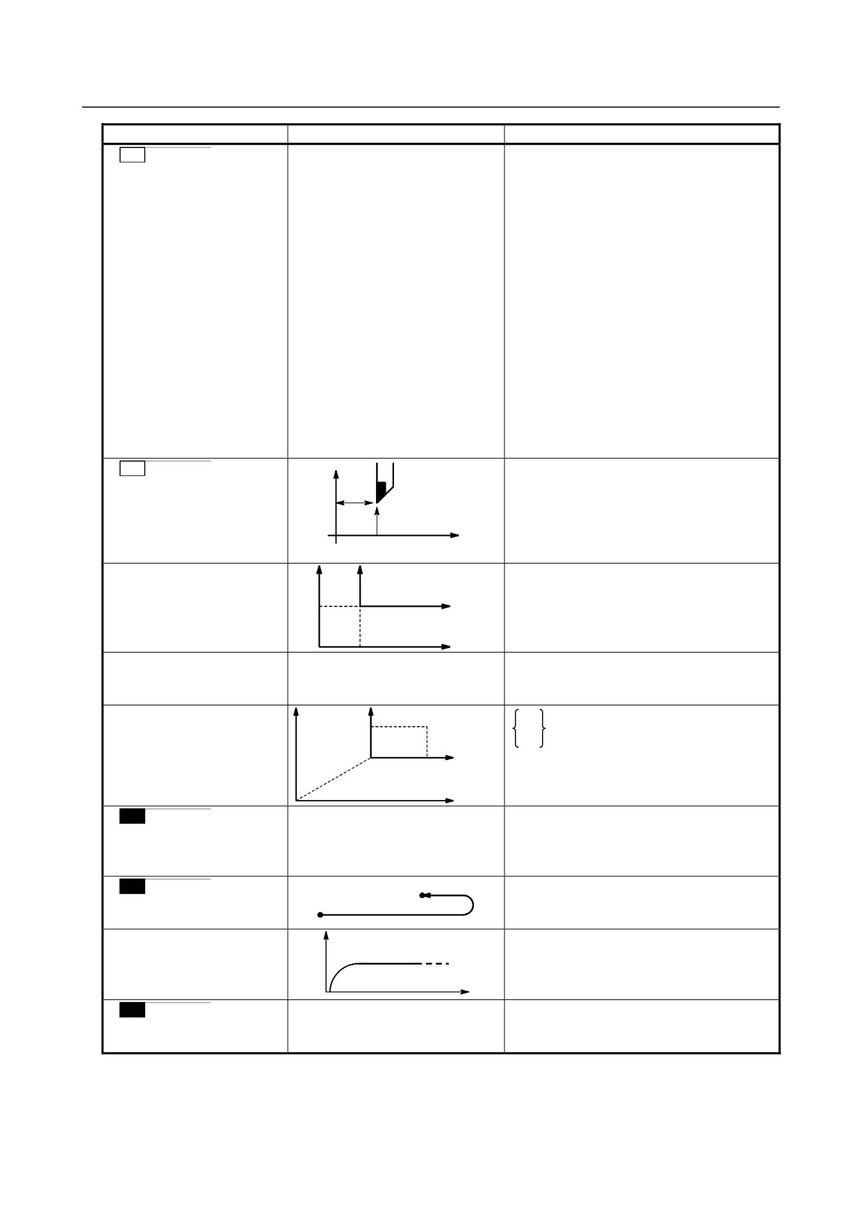
C. LIST OF FUNCTIONS AND
PROGRAM FORMAT
APPENDIX
B-64304EN/02
Functions
Illustration
Program format
T
G51.4 P_Q_(L_) ; Start synchronous control
Synchronous, composite, and
(L_ can be omitted.)
superimposed control by
G50.4 Q_ ; Cancel synchronous control.
program command
P : Number to identify synchronous master
(G50.4, G51.4, G50.5, G51.5,
axis
G50.6, G51.6)
Q : Number to identify synchronous slave
axis
L : Parking start command
G51.5 P_Q_ ; Start composite control
G50.5 P_Q_ ; Cancel composite control
P : Number to identify composite axis 1
Q : Number to identify composite axis 2
G51.6 P_Q_ ; Start superimposed control
G50.6 Q_ ; Cancel superimposed control
P : Number to identify superimposed master
axis
Q : Number to identify superimposed slave
axis
T
G50 IP_ ;
(Coordinate system setting)
X
Coordinate system setting
or
G50 S_ ;
(Maximum spindle speed clamp)
Maximum spindle speed
clamp
Z
(G50)
Local coordinate system
G52 IP_ ;
Local coordinate
setting
system
x
(G52)
IP
Workpiece
y
coordinate system
Command in machine
G53 IP_ ;
coordinate system
(G53)
Selection of workpiece
G54
IP
:
Workpiece
:
IP_ ;
coordinate system
G59
origin
(G54 to G59)
offset
Workpiece coordinate system
Machine coordinate system
M
Example) G54.1 P12 ;
Selection of additional
G54.1 Pn ; (n=1 to 48)
workpiece coordinate system
Select the additional workpiece
G54 Pn ; (n=1 to 48)
(G54.1,G54)
coordinate system 12.
M
G60 IP_ ;
IP
Single direction positioning
(G60)
Cutting mode (G64)
G64_ ; Cutting mode
v
Exact stop mode (G61)
G61_ ; Exact stop mode
Tapping mode (G63)
G63_ ; Tapping mode
G64
t
M
G62_ ; Automatic corner override
Automatic corner override
(G62)
- 946 -
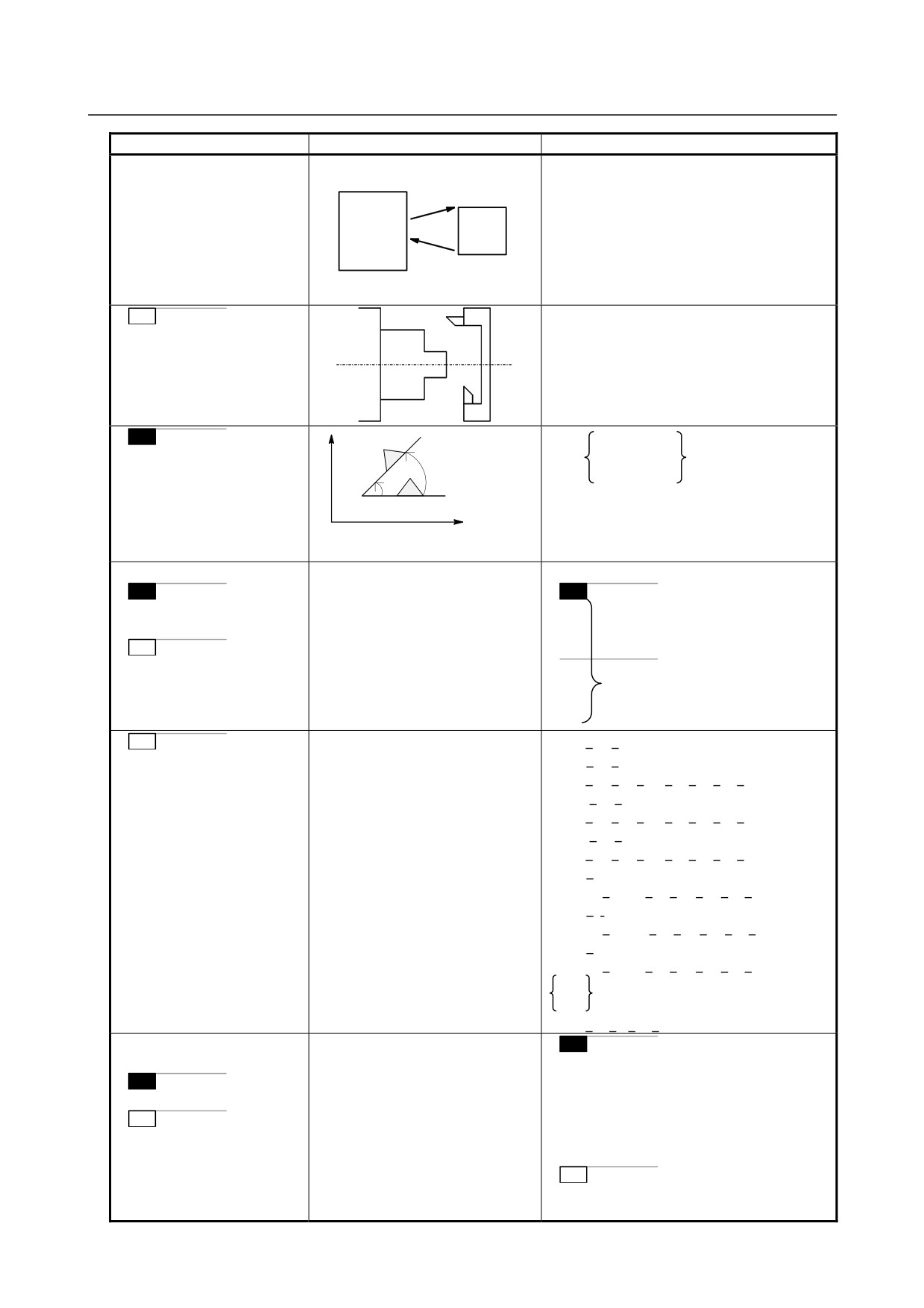
C.LIST OF FUNCTIONS AND
B-64304EN/02
APPENDIX
PROGRAM FORMAT
Functions
Illustration
Program format
Custom macro
One-shot call
(G65, G66, G67)
G65 P_ L_ <Argument assignment> ;
Macro
P : Program number
O_ ;
L : Number of repetition
G65 P_L_ ;
M99 ;
Modal call
G66 P_ L_ <Argument assignment> ;
Call after the move command
G67 ; Cancel
T
G68 : Mirror image for double turret
Mirror image for double turret
(G68, G69)
G69 : Mirror image cancel
M
G17 X_ Y_
Y
Coordinate system rotation
G68
G18 Z_ X_
R ;
(G68, G69)
G19 Y_ Z_
R
R: Angle of rotation in a counterclockwise
(x,y)
direction
X
In case of X-Y plane
G69 ; Cancel
Canned cycle for drilling
G80 ; Cancel
M
M
(G73, G74, G76, G80 to
G73
G89)
G74
T
G76
(G80 to G89)
X_Y_Z_P_Q_R_F_K_ ;
G81
:
G89
T
G70 P Q
;
Canned cycle for turning
G71 U R
;
Multiple repetitive canned
G71 P Q
U W F S T
;
cycle
G72 W R
;
(G70 to G76)
G72 P Q
U W F S T
;
Canned cycle
G73 W R
;
(G90, G92, G94)
G73 P Q
U W F S T
;
G74 R
;
G74 X(u) Z(w) P Q R F
;
G75 R
;
G75 X(u) Z(w ) P Q R F
;
G76 R
;
G76 X(u) Z(w) P Q R F
;
G90
X_ Z_ I_ F_ ;
G92
G94 X Z I F
;
Canned grinding cycle (for
M
grinding machine)
G75 I_ J_ K_ α_ R_ F_ P_ L_ ;
M
G77 I_ J_ K_ α_ R_ F_ P_ L_ ;
(G75 to G79)
G78 I_ (J_) K_ α_ F_ P_ L_ ;
T
G79 I_ J_ K_ α_ R_ F_ P_ L_ ;
(G71 to G74)
α : Arbitrary axis address of the grinding axis
T
G71 A_ B_ W_ U_ I_ K_ H_ ;
G72 P_ A_ B_ W_ U_ I_ K_ H_ ;
- 947 -
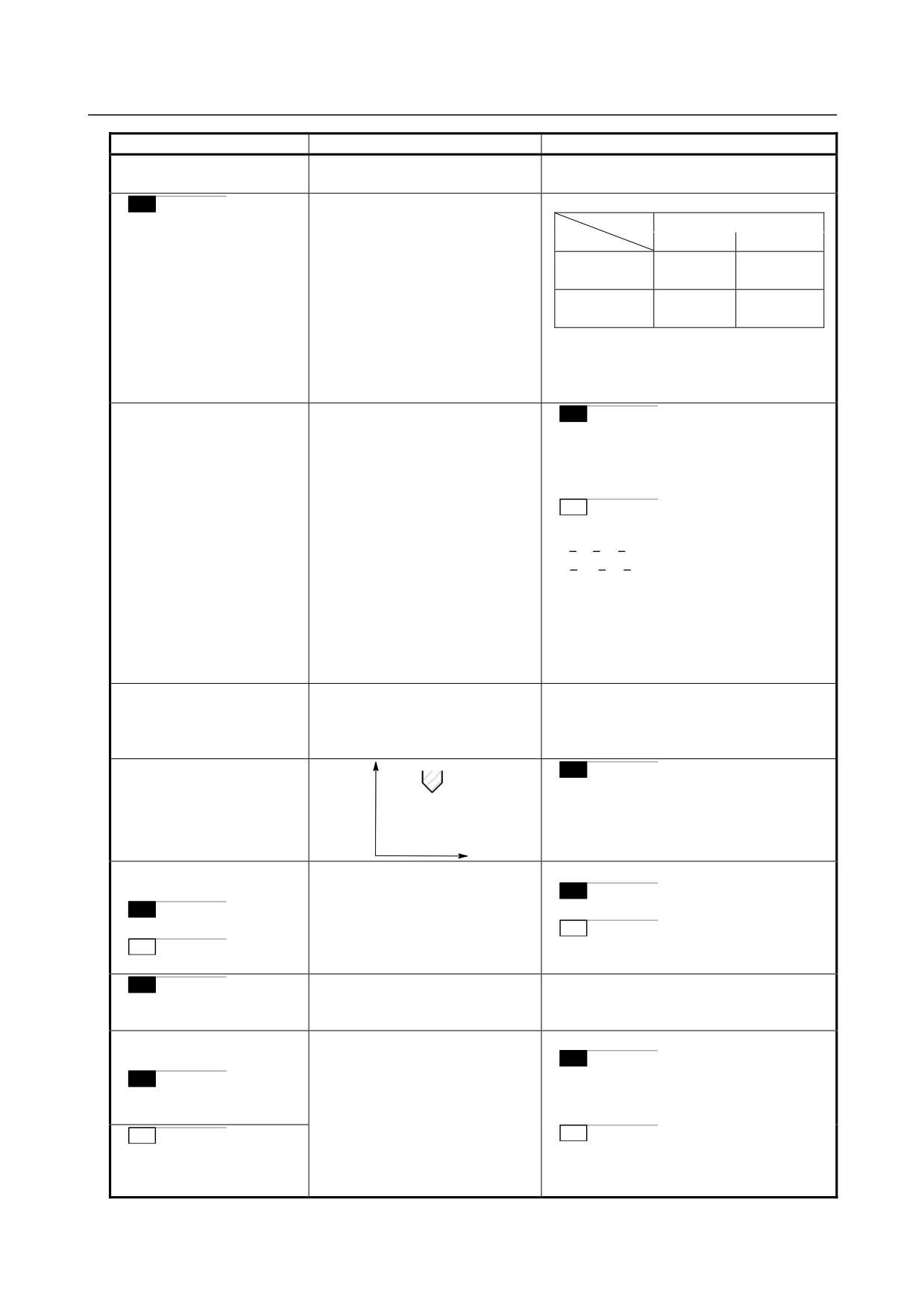
C. LIST OF FUNCTIONS AND
PROGRAM FORMAT
APPENDIX
B-64304EN/02
Functions
Illustration
Program format
G73 A_ (B_) W_ U_ K_ H_ ;
G74 P_ A_ (B_) W_ U_ K_ H_ ;
M
Electronic gear box
Parameter EFX(No.7731#0)
(G81,G80)
0
0
(G81.4,G80.4)
Start of
G81 T_ (L_)
G81 T_ (L_)
synchronization
(Q_ P_) ;
(Q_ P_) ;
Cancellation of
G80 ;
G80 ;
synchronization
T : Number of teeth
L : Number of hob threads
Q : Module or diametral pitch
P : Gear helix angle
Absolute/incremental
M
programming
G90_ ; Absolute programming
(G90/G91)
G91_ ; Incremental programming
:
G90_ . . . G91_ ; Programming in both modes
T
For G code system A
X Z C
: Absolute programming
U W H
:Incremental programming
For G code system B/C
G90_ ; Absolute programming
G91_ ; Incremental programming
:
G90_ … G91_ ; Programming in both
modes
Maximum incremental
G91.1 IP_ ;
command value check (G91.1)
IP_ ; Maximum incremental value
Set 0 to cancel maximum incremental value
check.
Change of workpiece
M
coordinate system
G92 IP_ ; Change of workpiece coordinate
IP
or
system
Maximum spindle speed
G92 S_ ; Constant surface speed control :
clamp (G92)
Maximum spindle speed clamp
Workpiece coordinate system
preset
M
M
G92.1 IP 0 ;
(G92.1)
T
T
G50.3 IP 0 ;
(G50.3)
M
G93 ; Inverse time setting mode
Inverse time feed
(G93)
Feed per minute,
M
Feed per revolution
M
G94 F_ ; Feed per minute
(G94, G95)
G95 F_ ; Feed per revolution
mm/min
inch/min
mm/rev
inch/rev
T
T
(G98, G99)
G98 F_ ; Feed per minute
G99 F_ ; Feed per revolution
- 948 -
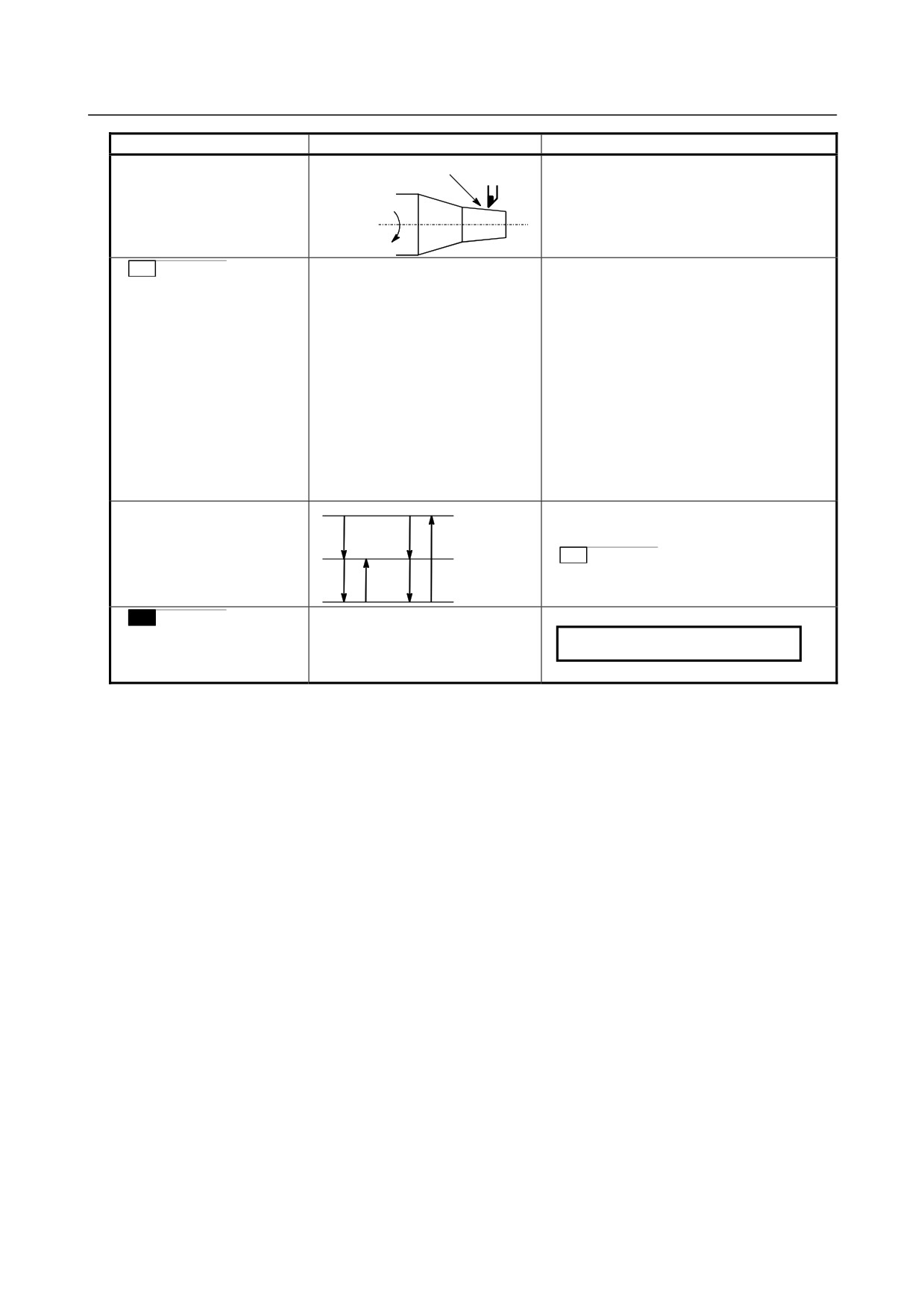
C.LIST OF FUNCTIONS AND
B-64304EN/02
APPENDIX
PROGRAM FORMAT
Functions
Illustration
Program format
Constant surface speed
Surface speed (m/min or feet/min)
G96 S_ ; Constant surface speed control on
control
(surface speed specification)
(G96, G97)
Spindle
G97 S_ ; Constant surface speed control off
speed
(spindle speed specification)
N(min-1)
T
G96.1 P_R_; The next block starts operating
Speed display function of a
upon completion of spindle
milling tool with servo motor
indexing (the SV speed control
(G96.1,G96.2,G96.3,G96.4)
mode is off).
G96.2 P_R_; The next block starts operating
without waiting for spindle
indexing to complete.
G96.3 P_; The next block starts operating
after confirming the completion
of spindle indexing (the SV
speed control mode is off).
G96.4 P_; The SV speed control mode is
on.
Canned cycle initial level
G98
Initial level
G98_ ; Canned cycle initial level return
return/R level return
G99_ ; Canned cycle R level return
(G98, G99)
G99
T
R level
They can be used only in the G code system
B/C.
Z point
M
G161 R_ ;
In-feed control (for grinding
Figure program (G01, G02, G03)
machine)
(G160, G161)
G160 ;
- 949 -
D.RANGE OF COMMAND VALUE
APPENDIX
B-64304EN/02
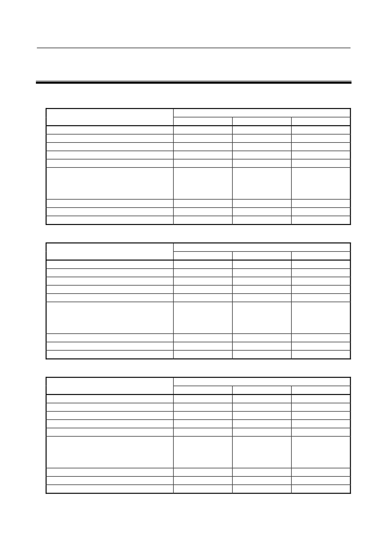
D RANGE OF COMMAND VALUE
Linear axis
-
In case of millimeter input, feed screw is millimeter
Increment system
IS-A
IS-B
IS-C
Least input increment (mm)
0.01
0.001
0.0001
Least command increment (mm)
0.01
0.001
0.0001
Max. programmable dimension (mm)
±999,999.99
±999,999.999
±99,999.9999
Max. rapid traverse (mm/min)*1
999,000
999,000
100,000
Feedrate range (mm/min)*1
0.01 to 999,000
0.001 to 999,000
0.0001 to 100,000
Incremental feed (mm/step)
0.01
0.001
0.0001
0.1
0.01
0.001
1.0
0.1
0.01
10.0
1.0
0.1
Tool compensation amount (mm)*2
0 to ±9,999.99
0 to ±9,999.999
0 to ±9,999.9999
Backlash compensation amount (pulses)*3
0 to ±9,999
0 to ±9,999
0 to ±9,999
Dwell (sec)*4
0 to 999,999.99
0 to 999,999.999
0 to 99,999.9999
-
In case of inch input, feed screw is millimeter
Increment system
IS-A
IS-B
IS-C
Least input increment (inch)
0.001
0.0001
0.00001
Least command increment (inch)
0.001
0.0001
0.00001
Max. programmable dimension (inch)
±39,370.078
±39,370.0787
±3,937.00787
Max. rapid traverse (mm/min)*1
999,000
999,000
100,000
Feedrate range (inch/min)*1
0.001 to 96,000
0.0001 to 9,600
0.00001 to 4,000
Incremental feed (inch/step)
0.001
0.0001
0.00001
0.01
0.001
0.0001
0.1
0.01
0.001
1.0
0.1
0.01
Tool compensation amount (inch)*2
0 to ±999.999
0 to ±999.9999
0 to ±999.99999
Backlash compensation amount (pulses)*3
0 to ±9,999
0 to ±9,999
0 to ±9,999
Dwell (sec)*4
0 to 999,999.99
0 to 999,999.999
0 to 99,999.9999
-
In case of inch input, feed screw is inch
Increment system
IS-A
IS-B
IS-C
Least input increment (inch)
0.001
0.0001
0.00001
Least command increment (inch)
0.001
0.0001
0.00001
Max. programmable dimension (inch)
±99,999.999
±99,999.9999
±9,999.99999
Max. rapid traverse (inch/min)*1
96,000
9,600
4,000
Feedrate range (inch/min)*1
0.001 to 96,000
0.0001 to 9,600
0.00001 to 4,000
Incremental feed (inch/step)
0.001
0.0001
0.00001
0.01
0.001
0.0001
0.1
0.01
0.001
1.0
0.1
0.01
Tool compensation amount (inch)*4
0 to ±999.999
0 to ±999.9999
0 to ±999.99999
Backlash compensation amount (pulses)*3
0 to ±9,999
0 to ±9,999
0 to ±9,999
Dwell (sec)*4
0 to 999,999.99
0 to 999,999.999
0 to 99,999.9999
- 950 -
B-64304EN/02
APPENDIX
D.RANGE OF COMMAND VALUE
-
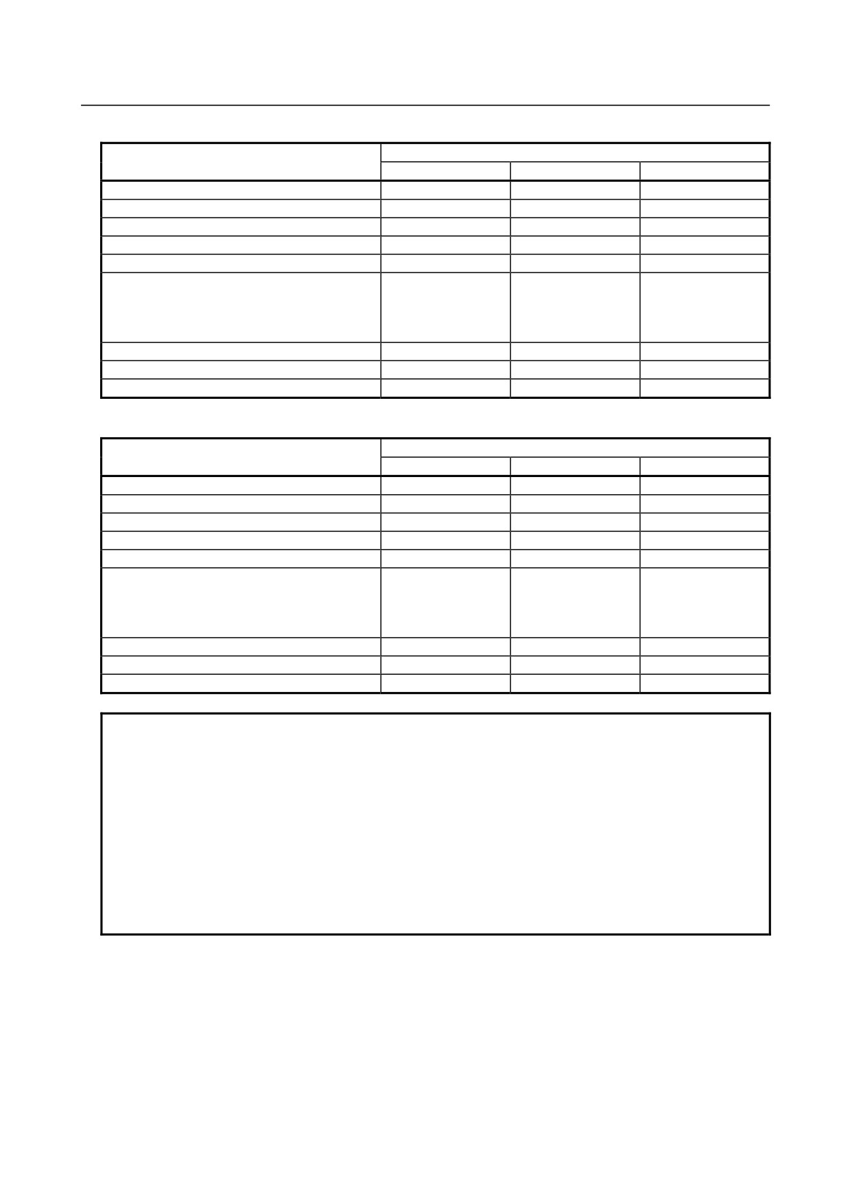
In case of millimeter input, feed screw is inch
Increment system
IS-A
IS-B
IS-C
Least input increment (mm)
0.01
0.001
0.0001
Least command increment (mm)
0.01
0.001
0.0001
Max. programmable dimension (mm)
±999,999.99
±999,999.999
±99,999.9999
Max. rapid traverse (inch/min)*1
96,000
9,600
4,000
Feedrate range (mm/min)*1
0.01 to 999,000
0.001 to 999,000
0.0001 to 100,000
Incremental feed (mm/step)
0.01
0.001
0.0001
0.1
0.01
0.001
1.0
0.1
0.01
10.0
1.0
0.1
Tool compensation amount (mm)*2
0 to ±9,999.99
0 to ±9,999.999
0 to ±9,999.9999
Backlash compensation amount (pulses)*3
0 to ±9,999
0 to ±9,999
0 to ±9,999
Dwell (sec)*4
0 to 999,999.99
0 to 999,999.999
0 to 99,999.9999
-
Rotary axis
Increment system
IS-A
IS-B
IS-C
Least input increment (deg)
0.01
0.001
0.0001
Least command increment (deg)
0.01
0.001
0.0001
Max. programmable dimension (deg)
±999,999.99
±999,999.999
±99,999.9999
Max. rapid traverse (deg/min)*1
999,000
999,000
100,000
Feedrate range (deg/min)*1
0.01 to 999,000
0.001 to 999,000
0.0001 to 100,000
Incremental feed (deg/step)
0.01
0.001
0.0001
0.1
0.01
0.001
1.0
0.1
0.01
10.0
1.0
0.1
Tool compensation amount (deg)*2
0 to ±9,999.99
0 to ±9,999.999
0 to ±9,999.9999
Backlash compensation amount (pulses)*3
0 to ±9,999
0 to ±9,999
0 to ±9,999
Dwell (sec)*4
0 to 999,999.99
0 to 999,999.999
0 to 99,999.9999
NOTE
*1 The feedrate range shown above are limitations depending on CNC interpolation
capacity. As a whole system, limitations depending on servo system must also
be considered.
*2 If the mode of input is switched between inch input and metric input, the
maximum compensation value that can be set at inch input time is (maximum
compensation value) × 1/25.4. If a value exceeding this value is specified at
inch input time, the compensation value is not converted to a metric value
correctly when the mode of input is switched to metric input.
*3 The unit is the detection unit.
*4 Depends on the increment system of the axis at in address X.
- 951 -
E.NOMOGRAPHS
APPENDIX
B-64304EN/02
E NOMOGRAPHS
Appendix E, "NOMOGRAPHS", consists of the following sections:
E.1 INCORRECT THREADED LENGTH
952
E.2 SIMPLE CALCULATION OF INCORRECT THREAD LENGTH
953
E.3 TOOL PATH AT CORNER
955
E.4 RADIUS DIRECTION ERROR AT CIRCLE CUTTING
957
E.1 INCORRECT THREADED LENGTH
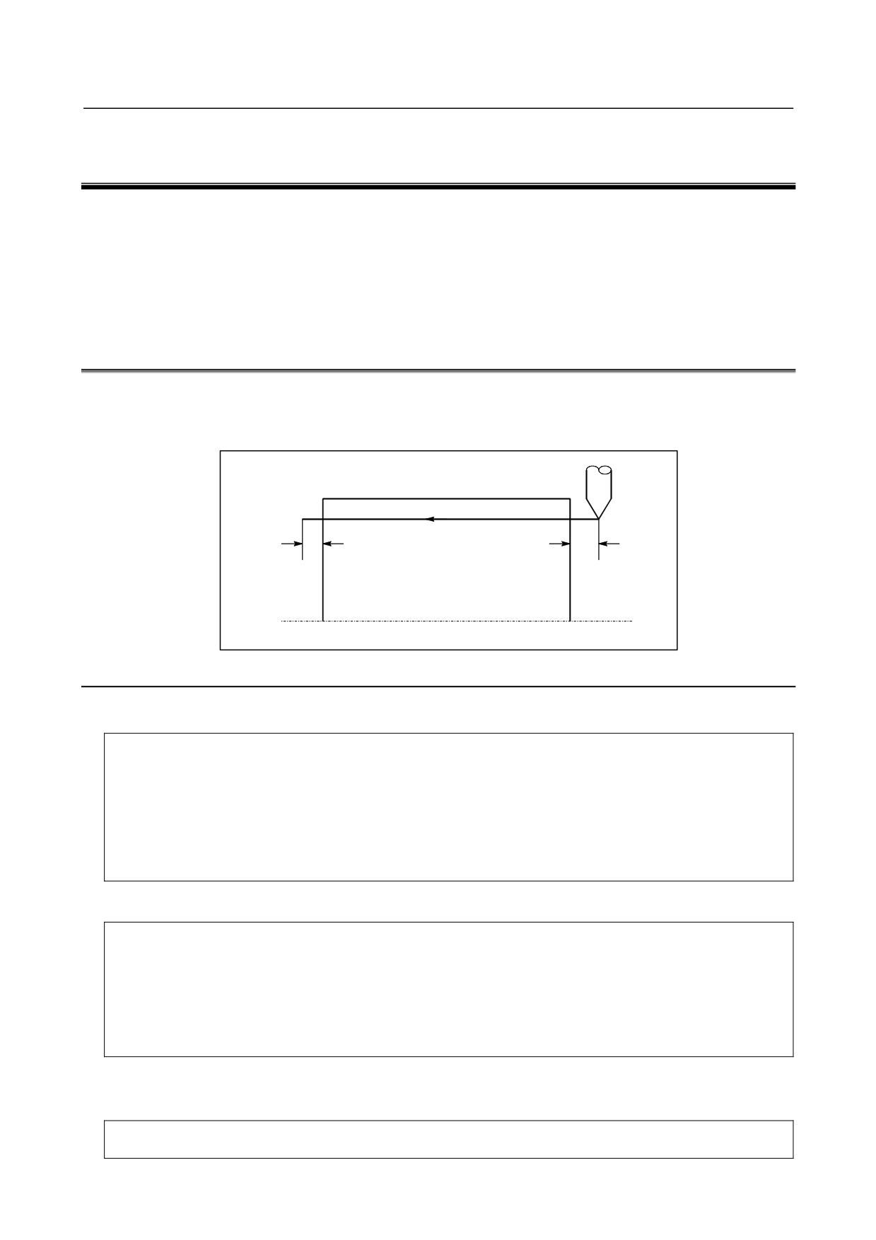
The leads of a thread are generally incorrect in δ1 and δ2, as shown in Fig. E.1 (a), due to automatic
acceleration and deceleration.
Thus distance allowances must be made to the extent of δ1 and δ2 in the program.
δ2
δ1
Fig. E.1 (a) Incorrect thread position
Explanation
-
How to determine
δ2
δ
=T V (mm
)
(1)
2
1
1
V =
60RL
T1
: Time constant of servo system (sec)
V
: Threading speed (mm/sec)
R
: Spindle speed (min-1)
L
: Thread feed (mm)
Tim
e constant T1 (sec) of the servo system: Usually 0.033 s.
-
How to determine δ1
t
δ
= {t - T
+ T exp( -
)} V
(2)
1
1
1
T
1
t
a = exp( -
(3)
T)
1
T1
: Time constant of servo system (sec)
V
: Threading speed (mm/sec)
Time constant T1 (sec) of the servo system: Usually 0.033 s.
The lead at the beginning of thread cutting is shorter than the specified lead L, and the allowable lead
error is ΔL. Then as follows.
ΔL
a=
L
- 952 -
B-64304EN/02
APPENDIX
E.NOMOGRAPHS
When the value of “a” is determined, the time lapse until the thread accuracy is attained. The time “t” is
substituted in (2) to determine δ1: Constants V and T1 are determined in the same way as for δ2. Since the
calculation of δ1 is rather complex, a nomography is provided on the following pages.
-
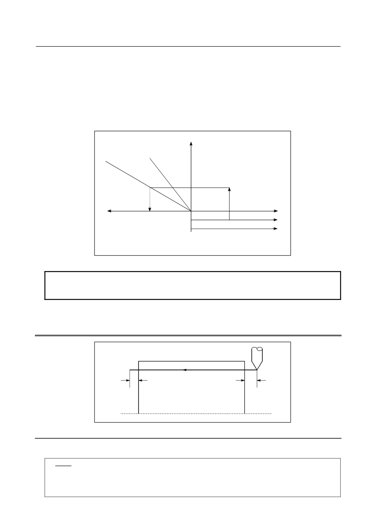
How to use nomograph
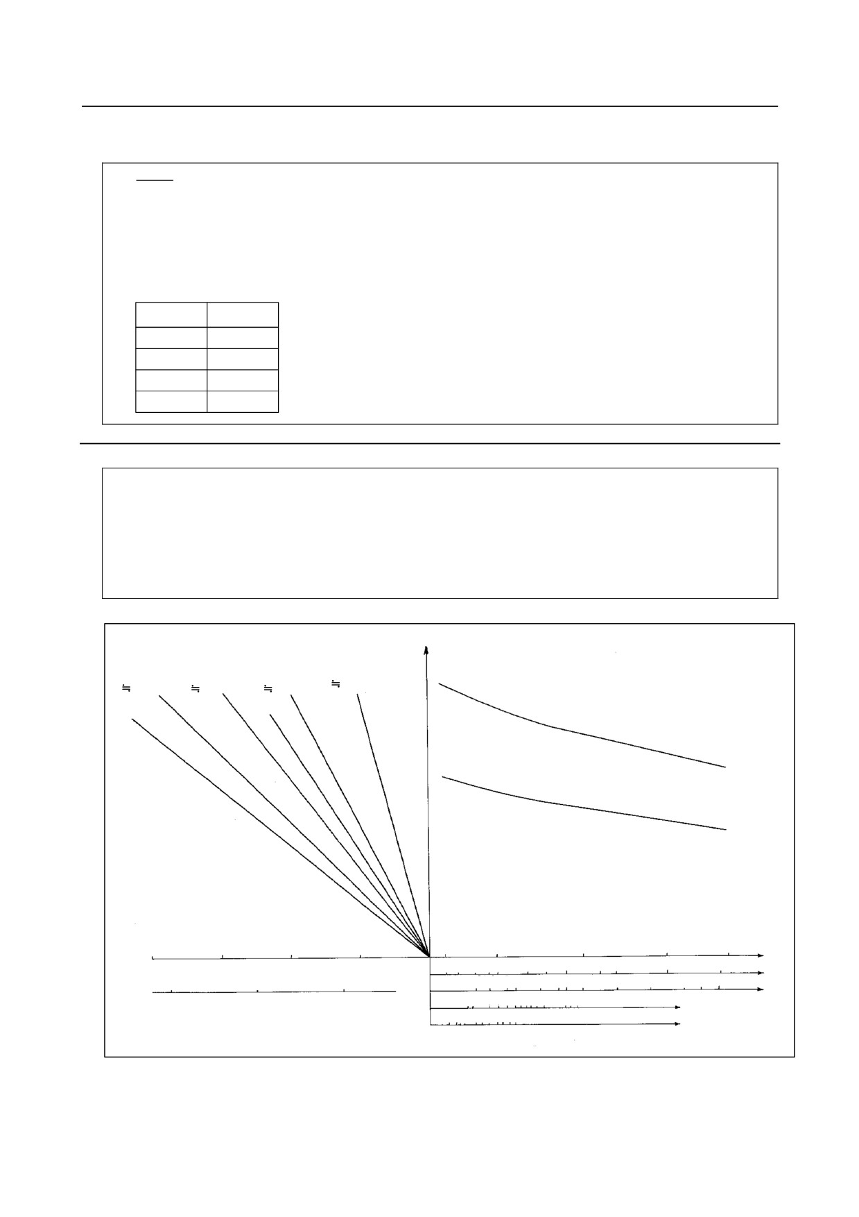
First specify the class and the lead of a thread. The thread accuracy, a, will be obtained at (1), and
depending on the time constant of cutting feed acceleration/ deceleration, the δ1 value when V = 10mm/s
will be obtained at (2). Then, depending on the speed of thread cutting, δ1 for speed other than 10mm/s
can be obtained at (3).
δ1(V=10mm/sec)
V=20mm/sec
V=40mm/sec
Time constant of servo system
(2)
T1
(3)
(1)
T2
δ1
a
0
L
L
(Note) See the graph in reference later in the manual for an actual example.
Fig. E.1 (b) Nomograph
NOTE
The equations for δ1, and δ2 are for when the acceleration/ deceleration time
constant for cutting feed is 0.
E.2 SIMPLE CALCULATION OF INCORRECT THREAD
LENGTH
δ2
δ1
Fig. E.2 (a) Incorrect threaded portion
Explanation
-
How to determine δ2
LR
a=
1800*(mm)
R : Spindle speed (min-1)
L : Thread lead (mm)
* When time constant T1 of the servo system is 0.033 s.
- 953 -
E.NOMOGRAPHS
APPENDIX
B-64304EN/02
-
How to determine δ1
LR
δ
=
1
1800*( - 1 - lna) (mm)
=δ ( - 1 - lna)(mm)
2
R : Spindle speed (min-1)
L : Thread lead (mm)
* When time constant T1 of the servo system is 0.033 s.
Following a is a permitted value of thread.
a
-1-lna
0.005
4.298
0.01
3.605
0.015
3.200
0.02
2.912
Example
R=350rpm
L=1mm
a=0.01
then
350×1
δ2 =
1800
= 0.194(mm)
δ
= δ ×3.605 = 0.701(mm)
1
2
Reference
δ1 (V=10mm/sec)
V : Speed in threading
V=10mm/sec
V=40mm/sec
V=30mm/sec
V=20mm/sec
(
0.39in/sec)
(
1.57in/sec)
(
1.18in/sec)
(
0.79in/sec)
V=2in/sec
V=1in/sec
Servo time constant
50msec
33msec
δ1
ΔL
8 (mm)
6
4
2
0
0.007
0.010
0.015
0.020
0.025
a= (
)
L
Metric thread
JIS class 1
3.3
3.0
2.52.0 1.5
1.2
1.0
0.9
0.7
0.
0.4
0.3 (mm)P Lead
δ1
JIS class 2
5.0
4.0
3.5
3.0
2.5
2.0
1.75
1.5
1.25
1.0
0.9
0.8
0.75 (mm)
P Lead
0.3 (in)
0.2
0.1
Unified thread
45
6
7 8 910 121314
161820
JIS 2A
Ridge/inch
JIS 3A
6
7 8 9 1012
14161820
(Theoretical accuracy)
あ
Ridge/inch
Fig. E.2 (b) Nomograph for obtaining approach distance δ1
- 954 -
B-64304EN/02
APPENDIX
E.NOMOGRAPHS
E.3 TOOL PATH AT CORNER
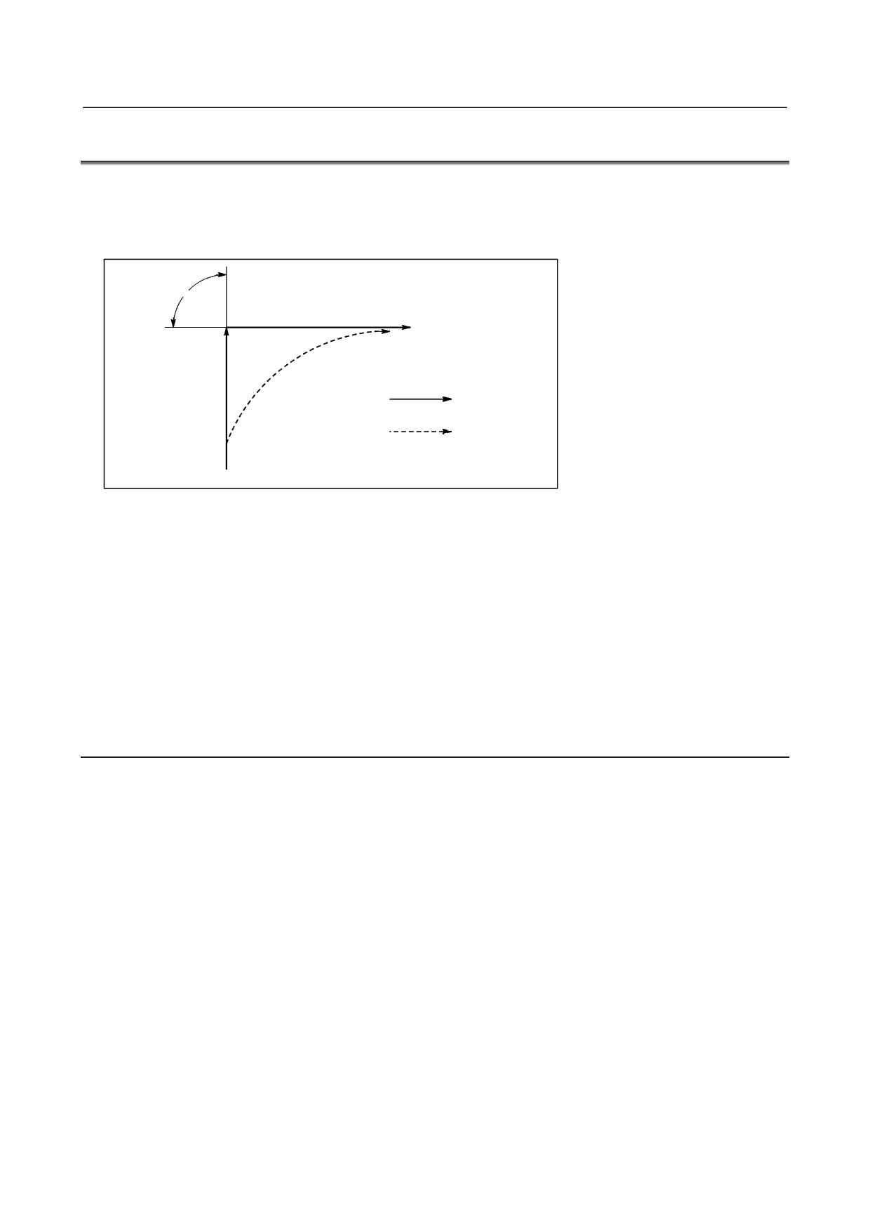
When servo system delay
(by exponential acceleration/deceleration at cutting or caused by the
positioning system when a servo motor is used) is accompanied by cornering, a slight deviation is
produced between the tool path (tool center path) and the programmed path as shown in Fig. E.3 (a).
Time constant T1 of the exponential acceleration/deceleration is fixed to 0.
θ
V2
Programmed path
Tool path
V1
Fig. E.3 (a) Slight deviation between the tool path and the programmed path
This tool path is determined by the following parameters:
• Feedrate (V
1, V2)
• Corner angle (θ)
•
Exponential acceleration / deceleration
time constant (T1) at cutting (T1
= 0)
•
Presence or absence of buffer register.
The above parameters are used to theoretically analyze the tool path and above tool path is drawn with the
parameter which is set as an example.
When actually programming, the above items must be considered and programming must be performed
carefully so that the shape of the workpiece is within the desired precision.
In other words, when the shape of the workpiece is not within the theoretical precision, the commands of
the next block must not be read until the specified feedrate becomes zero. The dwell function is then used
to stop the machine for the appropriate period.
Explanation
-
Analysis
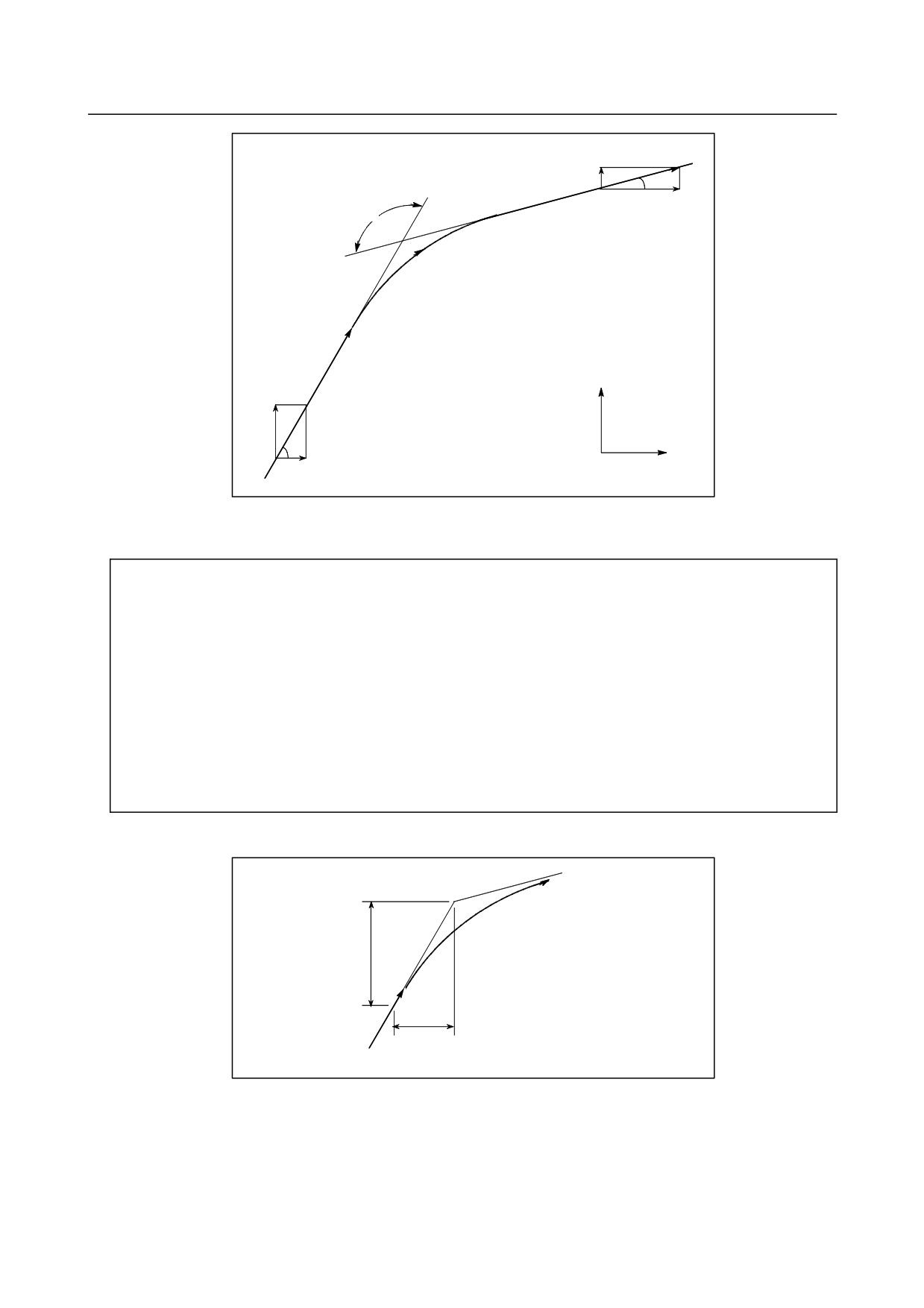
The tool path shown in Fig. E.3 (b) is analyzed based on the following conditions:
• Feedrate is constant at both blocks before and after cornering.
• The controller has a buffer register. (The error differs with the reading speed of the tape reader,
number of characters of the next block, etc.)
- 955 -
E.NOMOGRAPHS
APPENDIX
B-64304EN/02
V
VY2
φ2
VX2
θ
V
Z
VY1
φ2
VX1
0
X
Fig. E.3 (b) Example of tool path
-
Description of conditions and symbols
VX1 = Vcos φ1
VY1 = Vsin φ1
VX2 = Vcos φ2
VY2 = Vsin φ2
V
: Feedrate at both blocks before and after cornering
VX1 : X-axis component of feedrate of preceding block
VY1 : Y-axis component of feedrate of preceding block
VX2 : X-axis component of feedrate of following block
VY2 : Y-axis component of feedrate of following block
θ
: Corner angle
φ1
: Angle formed by specified path direction of preceding block and X-axis
φ2
: Angle formed by specified path direction of following block and X-axis
-
Initial value calculation
0
Y0
V
X0
Fig. E.3 (c) Initial value
The initial value when cornering begins, that is, the X and Y coordinates at the end of command
distribution by the controller, is determined by the feedrate and the positioning system time constant of
the servo motor.
- 956 -

B-64304EN/02
APPENDIX
E.NOMOGRAPHS
0
X =V (T
X1
1
+T
2
)
0
Y =V
Y1
(T
1
+T
2
)
T1: Exponential acceleration/deceleration time constant. (T=0)
T2: Time constant of positioning system (Inverse of position loop gain)
-
Analysis of corner tool path
The equations below represent the feedrate for the corner section in X-axis direction and Y-axis direction.
(
t
)
VX
1
t
t
V
X
=
(V
X2
−
X
V )[
1
1
−
1
{T exp(−
2
)−T exp(−
)}
+
V
X1
]
T
1
−
T
2
T
1
T
2
V
X1
t
t
=
V
X
[
2 1
−
1
{T exp(−
2
)−T exp(−
)}]
T
1
−
T
2
T
1
T
2
(
t
)
V
−
V
t
t
Y1
Y2
V
Y
=
{T
1
exp(−
)− T
2
exp(−
)}
+
V
Y2
T
1
−
T
2
T
1
T
2
Therefore, the coordinates of the tool path at time t are calculated from the following equations:
1
X(t)
X
V (t)dt
−X
0
=∫
0
V
X2
−
V
X1
t
2
t
=
1
{T 2 exp(−
)− T
2
exp(−
)}− V
X2
1
(T +T
2
−
t
)
T
1
−
T
2
T
1
T
2
1
Y(t)
Y
V (t)dt
−
Y
0
=∫
0
V
Y2
−
V
Y1
t
2
t
=
{T 2 exp(−
)− T
exp(−
)}− V
(T +T
−
t
)
1
2
Y2
1
2
T
−
T
T
T
1
2
1
2
E.4 RADIUS DIRECTION ERROR AT CIRCLE CUTTING
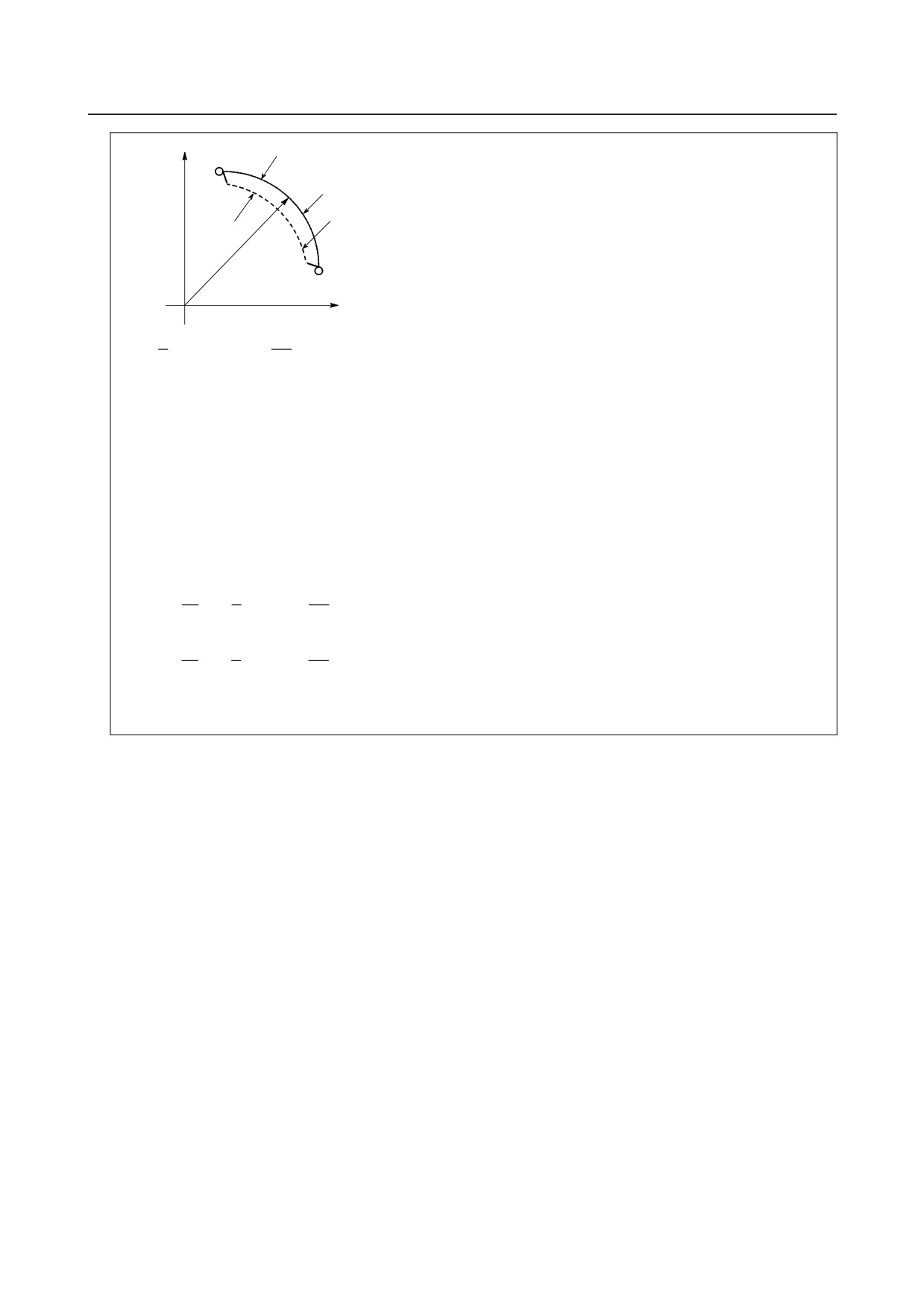
When a servo motor is used, the positioning system causes an error between input commands and output
results. Since the tool advances along the specified segment, an error is not produced in linear
interpolation. In circular interpolation, however, radial errors may be produced, specially for circular
cutting at high speeds.
This error can be obtained as follows:
- 957 -
E.NOMOGRAPHS
APPENDIX
B-64304EN/02
Y
Δr
Command path
Actual path
r
Z
2
1
2
2
2
V
Δr
=
(T
+T
(1-α
))
1
. . . 2 . (1)
2
r
Δr : Maximum radius error (mm)
v : Feedrate (mm/sec)
r
: Circle radius (mm)
T1: Exponential acceleration/deceleration time constant at cutting (sec) (T=0)
T2: Time constant of positioning system (sec)
(Inverse of position loop gain)
α : Feed forward coefficient (%)
In the case of bell-shaped acceleration/deceleration and linear acceleration/deceleration after cutting feed
interpolation, an approximation of this radius error can be obtained with the following expression:
Linear acceleration/deceleration after cutting feed interpolation
2
1
2
1
2
2
V
Δr
=
(
T
1
+
T
2
(1-α
))
24
2
r
Bell-shaped acceleration/deceleration after cutting feed interpolation
2
1
2
1
2
2
V
Δr
=
(
T
1
+
T
2
(1-α
))
48
2
r
Thus, the radius error in the case of bell-shaped acceleration/deceleration and linear acceleration/deceleration after
interpolation is smaller than in case of exponential acceleration/deceleration by a factor of 12, excluding any error
caused by a servo loop time constant.
Since the machining radius r (mm) and allowable error Δr
(mm) of the workpiece is given in actual
machining, the allowable limit feedrate v (mm /sec) is determined by equation (1).
Since the acceleration/deceleration time constant at cutting which is set by this equipment varies with the
machine tool, refer to the manual issued by the machine tool builder.
- 958 -

F.SETTINGS AT POWER-ON,
IN THE CLEAR STATE, OR
B-64304EN/02
APPENDIX
IN THE RESET STATE
F SETTINGS AT POWER-ON, IN THE CLEAR
STATE, OR IN THE RESET STATE
Either the clear state or reset state is entered during a reset is set by bit 6 (CLR) of parameter No. 3402 (0:
reset state/1: clear state).
The symbols in the figure below have the following meanings.
○ : The setting remains unchanged or the operation continues.
× : The setting is deleted or the operation stops.
Item
Power-on
Clear state
Reset state
Setting
Offset
○
○
○
s
Set data
○
○
○
Parameter
○
○
○
Various
Program in memory
○
○
○
data
Information of the block
items
read in advance during
×
×
×
automatic operation
N (sequence number)
× (Note 7)
× (Notes 1, 2, 7)
○ (Note 1, 2)
One-shot G code
×
×
×
Initial value (Note 3)
Initial value (Note 3)
G20 and G21 are set to
Modal G code
G20 and G21 are
not
○ (Note 2 and 6)
the state at the previous
changed (Note 2).
power-off.
F
0
0
○ (Note 2)
S, T, M
×
○ (Note 2)
○ (Note 2)
K (count specification)
×
×
×
Coordin
Workpiece coordinates
0 (Note 4)
○
○
ate
Operati
Movement
×
×
×
on
Dwell
×
×
×
during
M, S, T code output
×
×
×
executi
×
See
"Tool
Position
See
"Tool
Position
Tool position
on
Compensation
at
a
Compensation
at
a
compensation
Reset".
Reset".
×
Depending on the setting
Depending on the setting
Tool length
of bit 6 (LVK) of parameter
of bit 6 (LVK) of parameter
compensation
No. 5003
No. 5003
Tool radius/tool nose
×
×
×
radius compensation
Storing a called
×
× (Note 5)
×
subprogram
- 959 -
F. SETTINGS AT POWER-ON,
IN THE CLEAR STATE, OR
IN THE RESET STATE
APPENDIX
B-64304EN/02
Item
Power-on
Clear state
Reset state
Output
"0”(when no alarm cause
“0”
(when no alarm
“0”
(when no alarm
CNC alarm signal AL
signals
is present)
cause is present)
cause is present)
Reference position return
○ (or × for emergency
×
○(or × for emergency stop)
completion signal ZPx
stop)
S, T, B codes
×
○
○
M code
×
×
×
M, S, T, B strobe signals
×
×
×
Spindle rotation signal
×
○
○
(S analog signal)
CNC ready signal MA
“1”
○
○
“1”
“1”
“1”
Servo ready signal SA
(when a servo alarm does
(when a servo alarm does
(when a servo alarm does
not occur)
not occur)
not occur)
Cycle start signal STL
×
×
×
Feed hold signal SPL
×
×
×
Tool position compensation at a reset
○ : Cancelled.
× : Not canceled.
Bit 3 (LVC) of parameter No. 5006 and bit 7 (TGC) of parameter
Compensation method
No. 5003
LVC=0
LVC=1
LVC=0
LVC=1
TGC=0
TGC=0
TGC=1
TGC=1
Tool movement
Wear compensation
×
○
×
○
Geometry compensation
(Axis
(Axis movement)
movement)
Coordinate shift
Wear compensation
×
○
×
○
Geometry compensation
×
×
○
○
- 960 -

F.SETTINGS AT POWER-ON,
IN THE CLEAR STATE, OR
B-64304EN/02
APPENDIX
IN THE RESET STATE
NOTES
1
When the beginning position is found, the main program number is displayed.
2
If a reset is made during execution of a block, the states of the modal G code
and modal address (such as N, F, S, T, or M) specified in the block are not
reflected. The modal information specified in the previous and preceding
blocks is kept.
3
The initial value of the modal G code depends on the following parameters. For
details, refer to the parameter manual (B-63950).
- Parameter G01 (No.3402#0)
- Parameter G18 (No.3402#1)
- Parameter G19 (No.3402#2)
- Parameter G91 (No.3402#3)
- Parameter FPM (No.3402#4)
- Parameter G23 (No.3402#7)
- Parameters No. 3406 to No. 3409
4
For detection of an absolute position, the value is generated from machine
coordinates and a workpiece origin offset.
5
When a reset is made during execution of a subprogram, a return to the main
program is performed. Execution at a midpoint in the subprogram is
impossible.
6
When one of the following two settings, which hold the modal G code in group 1
by a reset is set:
- Reset state (bit 6 of parameter No. 3402 is 0)
- Clear state (bit 1 of parameter No. 3402 is 1) and
the modal G code in group 1 is held at a time of a reset (bit 1 of parameter No.
3406 is 1),
if a reset is made during execution of one of the following canned cycles, which
cause cycle operation, the mode of the modal G code in group 1 is changed to
the G01 mode.
- G90 : Outer surface/inner surface turning cycle
- G92 : Threading cycle
- G94 : Edge turning cycle
7
When bit 0 (SEK) of parameter No. 11353 is set to 1, sequence number N can
be held even at power-on or in the clear state.
- 961 -

G. CHARACTER-TO-CODES
CORRESPONDENCE
APPENDIX
B-64304EN/02
G CHARACTER-TO-CODES
CORRESPONDENCE TABLE
Appendix G, "CHARACTER-TO-CODES CORRESPONDENCE TABLE", consists of the following
sections:
G.1 CHARACTER-TO-CODES CORRESPONDENCE TABLE
962
G.2 FANUC DOUBLE-BYTE CHARACTER CODE TABLE
963
G.1
CHARACTER-TO-CODES CORRESPONDENCE TABLE
Character
Code
Comment
Character
Code
Comment
A
065
6
054
B
066
7
055
C
067
8
056
D
068
9
057
E
069
032
Space
F
070
!
033
Exclamation mark
G
071
”
034
Quotation mark
H
072
#
035
Sharp
I
073
$
036
Dollar sign
J
074
%
037
Percent
K
075
&
038
Ampersand
L
076
’
039
Apostrophe
M
077
(
040
Left parenthesis
N
078
)
041
Right parenthesis
O
079
042
Asterisk
P
080
+
043
Plus sign
Q
081
,
044
Comma
R
082
-
045
Minus sign
S
083
046
Period
T
084
/
047
Slash
U
085
:
058
Colon
V
086
;
059
Semicolon
W
087
<
060
Left angle bracket
X
088
=
061
Equal sign
Y
089
>
062
Right angle bracket
Z
090
?
063
Question mark
0
048
@
064
At mark
1
049
[
091
Left square bracket
2
050
]
093
Right square bracket
3
051
^
094
4
052
_
095
Underscore
5
053
- 962 -
G.CHARACTER-TO-CODES
B-64304EN/02
APPENDIX
CORRESPONDENCE TABLE
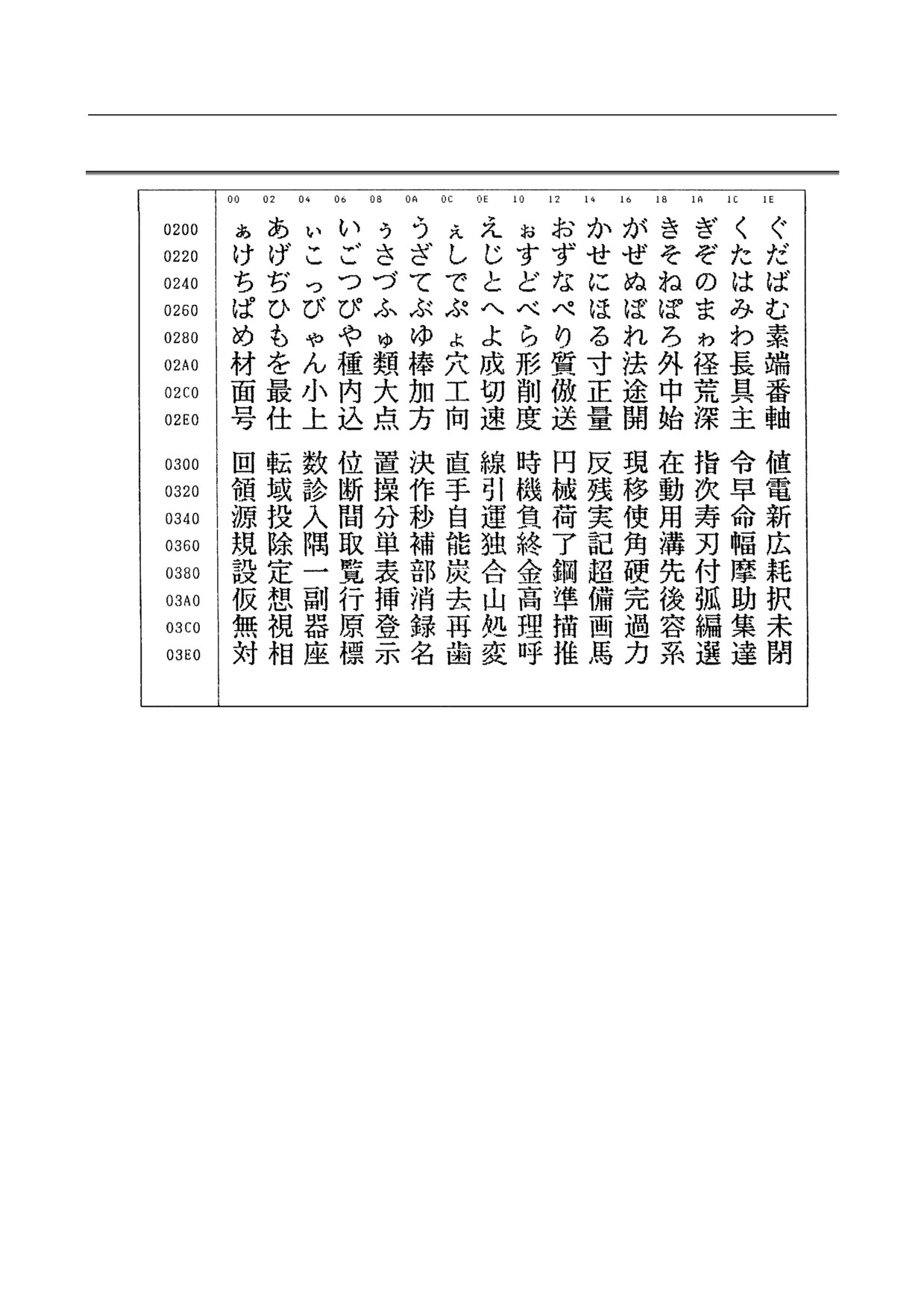
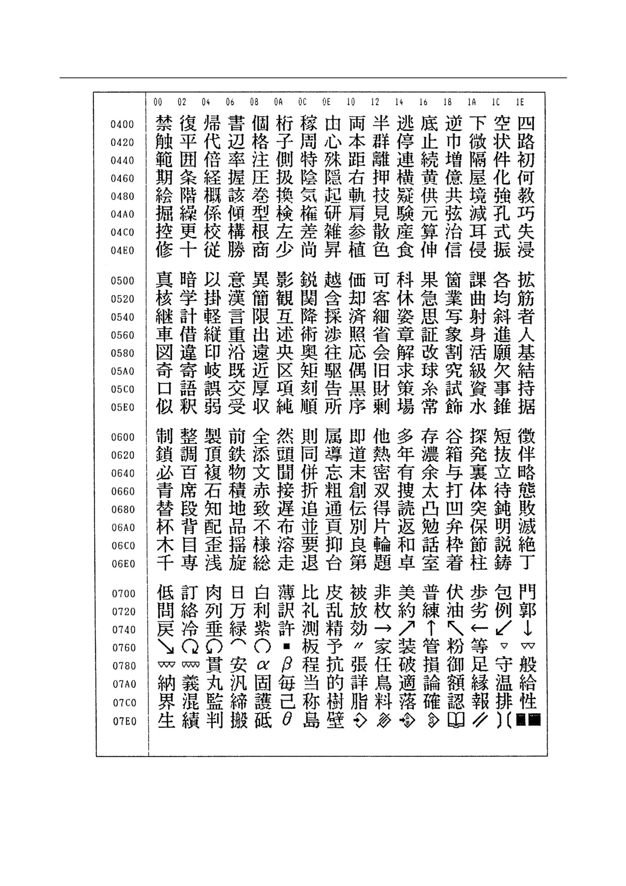
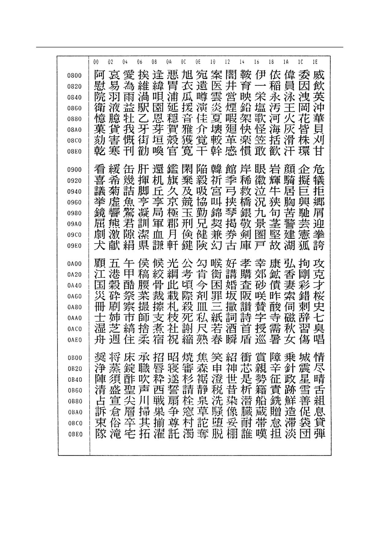
G.2 FANUC DOUBLE-BYTE CHARACTER CODE TABLE
- 963 -
G. CHARACTER-TO-CODES
CORRESPONDENCE
APPENDIX
B-64304EN/02
- 964 -
G.CHARACTER-TO-CODES
B-64304EN/02
APPENDIX
CORRESPONDENCE TABLE
- 965 -