FANUC Series 0i-MODEL D, Series 0i Mate-MODEL D. OPERATOR'S MANUAL - page 31

A.PARAMETERS
APPENDIX
B-64304EN/02
6713
Number of required parts
[Input type] Setting input
[Data type] 2-word path
[Valid data range] 0 to 999999999
This parameter sets the number of required machined parts.
Required parts finish signal PRTSF <F0062.7> is output to PMC when the number of
machined parts reaches the number of required parts. The number of parts is regarded as
infinity when the number of required parts is zero. The PRTSF signal is then not output.
6750
Integrated value of power-on period
[Input type] Parameter input
[Data type] 2-word path
[Unit of data] min
[Valid data range] 0 to 999999999
This parameter displays the integrated value of power-on period.
6751
Operation time (integrated value of time during automatic operation) 1
[Input type] Setting input
[Data type] 2-word path
[Unit of data] msec
[Valid data range] 0 to 59999
For details, see the description of parameter No. 6752.
6752
Operation time (integrated value of time during automatic operation) 2
[Input type] Setting input
[Data type] 2-word path
[Unit of data] min
[Valid data range] 0 to 999999999
This parameter displays the integrated value of time during automatic operation (neither
stop nor hold time included).
The actual time accumulated during operation is the sum of this parameter No. 6751 and
parameter No. 6752.
6753
Integrated value of cutting time 1
[Input type] Setting input
[Data type] 2-word path
[Unit of data] msec
[Valid data range] 0 to 59999
For details, see the description of parameter No. 6754.
6754
Integrated value of cutting time 2
[Input type] Setting input
[Data type] 2-word path
[Unit of data] min
[Valid data range] 0 to 999999999
This parameter displays the integrated value of a cutting time that is performed in cutting
feed such as linear interpolation (G01) and circular interpolation (G02 or G03).
The actual time accumulated during cutting is the sum of this parameter No. 6753 and
parameter No. 6754.
- 876 -
B-64304EN/02
APPENDIX
A.PARAMETERS
#7
#6
#5
#4
#3
#2
#1
#0
6800
M6T
IGI
SNG
GRS
SIG
LTM
GS2
GS1
[Input type] Parameter input
[Data type] Bit path
#0 GS1
#1 GS2 For the maximum number of groups set in parameter No. 6813, up to four tools can be
registered per group. The combination of the number of registrable groups and the
number of tools per group can be changed by setting GS1 and GS2.
GS2
GS1
Number of groups
Number of tools
0
0
1 to maximum number of groups (No. 6813)/8
1 to 16
0
1
1 to maximum number of groups (No. 6813)/4
1 to 8
1
0
1 to maximum number of groups (No. 6813)/2
1 to 4
1
1
1 to maximum number of groups (No. 6813)
1 to 2
NOTE
After changing these parameters, set data again by using G10
L3 ;(registration after deletion of data of all groups).
#2 LTM The tool life count is specified by:
0: Count.
1: Duration.
NOTE
After changing this parameter, set data again by using G10
L3 ;(registration after deletion of data of all groups).
#3 SIG When a tool is skipped by a signal, the group number is:
0: Not input by the tool group number selection signals.
1: Input by the tool group number selection signals.
NOTE
When this parameter is set to 0, a tool of the currently used group is
skipped.
#4 GRS When the tool change reset signal (TLRST) is input:
0: If the life of the group specified by the tool group number selection signals has
expired, the execution data of the group is cleared.
1: The execution data of all registered groups is cleared.
If this parameter is set to 1, the execution data of all registered groups is cleared also
when the clear operation to clear execution data is performed on the tool life management
list screen.
#5 SNG When the tool skip signal (TLSKP) is input while a tool not controlled by the tool life
management function is being used:
0: A tool of the most recently used group or a specified group (bit 3 (SIG) of parameter
No. 6800) is skipped.
1: The tool skip signal is ignored.
- 877 -

A.PARAMETERS
APPENDIX
B-64304EN/02
#6 IGI Tool back numbers are:
0: Not ignored.
1: Ignored.
#7 M6T A T code specified in the same block as M06 is:
0: Assumed to be a back number.
1: Assumed to be a command specifying the next tool group.
#7
#6
#5
#4
#3
#2
#1
#0
M6E
EMD
LVF
TSM
6801
M6E
EMD
LVF
[Input type] Parameter input
[Data type] Bit path
#1 TSM In the tool life management function, life counting is performed as follows when more
than one offset is specified:
0: Counting is performed for each tool number.
1: Counting is performed for each tool.
#2 LVF When the life value is counted by duration in the tool life management function, tool life
count override signals *TLV0 to *TLV9 <G049.0 to G050.1> are:
0: Not used.
1: Used.
#3 EMD In the tool life management function, the mark "*" indicating that the life has expired is
displayed when:
0: The next tool is used.
1: The life has just expired.
NOTE
If this parameter is set to 0, the "@" mark (indicating that the tool is
in use) is kept displayed unless the next tool whose life has not
expired is used. If this parameter is set to 1, marks are displayed in
different ways depending on the life count type.
If the life count type is the duration specification type, the "*" mark
(indicating that the life has expired) appears when the life has
expired. If the life count type is the count specification type, one
count is not assumed until the end of the program (M02, M30, and so
on). Therefore, even when the life value and the tool life counter
value match, the "*" mark (life has expired) does not appear. The "*"
mark (life has expired) appears when the tool is used again by a tool
group command (T code) or tool change command (M06) issued
after the CNC is reset.
#7
M6E When a T code is specified in the same block as M06:
0: The T code is treated as a back number or the group number to be selected next.
Which number is assumed depends on the setting of bit 7 (M6T) of parameter No.
6800.
1: Life counting for the tool group starts immediately.
- 878 -
B-64304EN/02
APPENDIX
A.PARAMETERS
#7
#6
#5
#4
#3
#2
#1
#0
6802
RMT
TSK
E17
TCO
T99
[Input type] Parameter input
[Data type] Bit path
#0 T99 When M99 of the main program is executed, and there is a the life was expired tool
group:
0: The tool change signal is not output.
1: The tool change signal is output, and the automatic operation becomes a stopped
state..
If the life count is specified by use count and this parameter 1, the tool change signal
TLCH <Fn064.0> is output and the automatic operation becomes a stopped state if the
life of at least one tool group has expired when the M99 command is specified.
If the life count type is the duration specification type, the automatic operation becomes a
stopped state if the life of at least one tool group has expired when the M99 command is
specified.
M
If the life count is specified by use count, after the M99 command is specified, a tool
group command (T code) selects, from a specified group, a tool whose life has not
expired, and the next tool change command (M06) increments the tool life counter by
one.
T
If the life count is specified by use count, 㨣hen a tool group command (T code) is
specified after the M99 command is specified, a tool whose life has not expired is
selected from a specified group, and the tool life counter is incremented by one.
#1 TCO
#2 E17
Specifies whether to allow the FOCAS2 or PMC window function to write tool
information of a group being used or a group to be used next during automatic operation
(the OP signal is set to "1").
6802#1(TCO)
1
Condition
0
6802#2(E17)
1
0
During
Group being used or to be
Tool being used
×
○
automatic
used next
Tool not being used
×
○
○
operation
Group neither being used nor to be used next
○
○
○
Not during automatic operation
○
○
○
○: Tool information can be written from FOCAS2 and PMC window.
×: Tool information cannot be written from FOCAS2 and PMC window.
When an attempt is made to write tool information from PMC window, completion
code 13 (REJECT ALARM) is returned.
:
Tool information cannot be cleared.
- 879 -

A.PARAMETERS
APPENDIX
B-64304EN/02
NOTE
When tool information of a tool being used (marked with "@") in the
group being used or to be used next or tool information of the most
recently used tool (marked with "@") in a group that is neither the
group being used nor the group to be used next is cleared, the life
counter is reset to 0.
It is possible to modify tool information of a tool in the group to be
used next. However, because tool selection is already completed,
the selected tool does not change even when the tool information is
modified.
This parameter has no influence on modifications to tool information
by edit operations from the tool life management screen.
#6 TSK If the count type in tool life management is the duration type, then when the last tool of a
group is skipped by a signal:
0: The count value for the last tool equals the life value.
1: The count value for the last tool remains unchanged.
#7 RMT Tool life arrival notice signal TLCHB is turned on and off as follows:
0: The signal is turned on if the remaining life value (the life value minus the life
counter value) is smaller than or equal to the remaining life setting. The signal is
turned off if the remaining life value (the life value minus the life counter value) is
greater than the remaining life setting.
1: The signal is turned on if the remaining life value (the life value minus the life
counter value) is equal to the remaining life setting. The signal is turned off if the
remaining life value (the life value minus the life counter value) is not equal to the
remaining life setting.
NOTE
When using the life count override feature, set bit 7 (RMT) of
parameter No. 6802 to 0. When the life count is specified by duration,
the unit used for determining the result of comparison between the
remaining life and the remaining life setting varies depending on the
life count interval (bit 0 (FCO) of parameter No. 6805). If the life is
counted every second, the comparison is made in units of 1 minute; if
the life is counted every 0.1 second, the comparison is made in units
of 0.1 minute.
#7
#6
#5
#4
#3
#2
#1
#0
6804
LFI
ETE
TCI
[Input type] Parameter input
[Data type] Bit path
#1 TCI During automatic operation (the OP signal is "1"), editing of tool life data is:
0: Disabled.
1: Enabled.
- 880 -
B-64304EN/02
APPENDIX
A.PARAMETERS
NOTE
When this parameter is set to 1, tool life data can be edited even
during automatic operation (the OP signal is "1"). If the target group
for editing is the group being used or the group to be used next,
however, only presetting of the life counter is permitted, and other
data cannot be modified.
#2 ETE In the tool life management screen, the mark of the tool at the life was expired of the final
tool in the group :
0: depends on setting parameter EMD (No.6801#3).
1: is "*" mark.
If bit 2 (ETE) of parameter No. 6804 is set to 1, when the life counter of the final tool in
the group becomes equal to the life value, display mark "*" in the final tool of the tool life
management screen.
When tool change signal TLCH<Fn064.0> is "1", the state of the life was expired of the
tool can be read by reading tool information on the final tool in FOCAS2 or the PMC
window.
#6 LFI In tool life management, counting of the life of a selected tool is:
0: Enabled.
1: Enabled or disabled according to the status of tool life counting disable signal
LFCIV<G048.2>.
#7
#6
#5
#4
#3
#2
#1
#0
6805
TAD
TRU
TRS
FGL
FCO
[Input type] Parameter input
[Data type] Bit path
#0 FCO If the life count type is the duration specification type, the life is counted as follows:
0: Every second.
1: Every 0.1 second.
According to the setting of this parameter, the increment system of life values and tool
life counter values displayed on the tool life management screen is set as follows:
Parameter FCO
0
1
Increment system for display and setting of life values and
1-minute
0.1-minute
life counter values
increments
increments
NOTE
After changing the setting of this parameter, set data again by using
G10L3;(registration after deletion of data of all groups).
#1 FGL If the life count type is the duration specification type, life data registered by G10 is:
0: In one-minute increments.
1: In 0.1-second increments.
- 881 -

A.PARAMETERS
APPENDIX
B-64304EN/02
#5 TRS Tool change reset signal TLRST is valid when reset signal RST is not "1" and:
0: The reset state (automatic operation signal OP is "0") is observed.
1: The reset state (automatic operation signal OP is "0"), automatic operation stop state
(The STL and SPL signals are "0" and the OP signal is "1"), or the automatic
operation pause state (the STL signal is "0" and the SPL signal is "1") is observed.
The TLRST signal, however, is invalid when the automatic operation stop state,
automatic operation pause state, and automatic operation start state (the STL signal
is "1") is observed during execution of a data setting command (G10L3).
#6 TRU When the life count type is the duration specification type, and the life is counted every
second (bit 0 (FCO) of parameter No. 6805 is set to 0):
0: Cutting time less than one second is discarded and is not counted.
1: Cutting time less than one second is rounded up and is counted as one second.
NOTE
If the life is counted every 0.1 second (bit 0 (FCO) of parameter No.
6805 is set to 1), cutting time less than 0.1 second is always rounded
up and is counted as 0.1 second.
#7 TAD With tool change type D (bit 7 (M6E) of parameter No. 6801 is set to 1), when a block
specifying M06 contains no T command:
0: An alarm PS0153 is issued.
1: No alarm is issued.
6810
Tool life management ignore number
[Input type] Parameter input
[Data type] 2-word path
[Valid data range] 0 to 99999999
This parameter sets the tool life management ignore number.
When the value specified in a T code exceeds the value set in this parameter, the value
obtained by subtracting the parameter-set value from the T code value is assumed to be
the tool group number for tool life management.
6811
Tool life count restart M code
[Input type] Parameter input
[Data type] Byte path
[Valid data range] 0 to 127 (except 01, 02, 30, 98, and 99)
When 0 is specified, it is ignored.
When the life is specified by count, the tool change signal (TLCH) is output if the life of
at least one tool group has expired when the tool life count restart M code is issued.
The T code (tool life management group command) specified after the tool life count
restart M code selects a tool whose life has not expired from a specified group, and the
next M06 command increments the tool life counter by one.
When the life is specified by duration, specifying the tool life count restart M code causes
nothing. When 0 is set in this parameter, the tool life count restart M code is invalid.
When the data of M code exceeds 127 values, set 0 in parameter No.6811, and set the
value of M code in parameter No.13221. The data range of parameter No.13221 is from 0
to 255.
- 882 -
B-64304EN/02
APPENDIX
A.PARAMETERS
6813
Maximum number of groups in tool life management
NOTE
When this parameter is set, the power must be turned off before
operation is continued.
[Input type] Parameter input
[Data type] Word path
[Unit of data] Group
[Valid data range] 0, 8, 16 to 128
This parameter sets the maximum number of groups to be used for each path. As the
maximum number of groups, set a multiple of eight. When this parameter is 0, 128
groups are set. Up to 128 groups can be set for each path.
NOTE
If the power is turned on after this parameter is changed, all data in
the tool life management file is initialized. Therefore, the life
management data of all paths that use the tool life management
function must be set.
6844
Remaining tool life (use count)
[Input type] Parameter input
[Data type] Word path
[Valid data range] This range is the same as the tool life range.
This parameter sets a remaining tool life (use count) used to output the tool life arrival
notice signal when the tool life is specified by use count. If a value greater than the tool
life value or 0 is set in this parameter, the tool life arrival notice signal is not output.
6845
Remaining tool life (use duration)
[Input type] Parameter input
[Data type] 2-word path
[Unit of data] min
[Valid data range] Not greater than the tool life value
This parameter sets the remaining tool life (use duration) used to output the tool life
arrival notice signal when the tool life is specified by use duration. If a value greater than
the tool life value or 0 is specified in this parameter, the tool life arrival notice signal is
not output.
NOTE
When the life is counted every 0.1 second (bit 0 (FCO) of parameter
No. 6805 = 1), the parameter value is in 0.1-minute increments.
6930
Maximum value of the operating range of the 1st position switch
to
to
6945
Maximum value of the operating range of the 16th position switch
[Input type] Parameter input
[Data type] Real path
[Unit of data] mm, inch, degree (machine unit)
[Min. unit of data] Depend on the increment system of the reference axis
- 883 -
A.PARAMETERS
APPENDIX
B-64304EN/02
[Valid data range] 9 digit of minimum unit of data (refer to standard parameter setting table (A))
(When the increment system is IS-B, -999999.999 to +999999.999)
Set the maximum value of the operating range of the first to sixteenth position switches.
NOTE
1 For a diameter-specified axis, use diameter values to specify the
parameters used to set the maximum and minimum values of an
operating range.
2 The position switch function is enabled upon completion of
reference position return.
3 The parameter No.6940 to No.6945 is effective when bit 1 (EPW)
of parameter No.6901 is set to 1.
6950
Minimum value of the operating range of the 1st position switch
to
to
6965
Minimum value of the operating range of the 16th position switch
[Input type] Parameter input
[Data type] Real path
[Unit of data] mm, inch, degree (machine unit)
[Min. unit of data] Depend on the increment system of the reference axis
[Valid data range] 9 digit of minimum unit of data (refer to standard parameter setting table (A))
(When the increment system is IS-B, -999999.999 to +999999.999)
Set the minimum value of the operating range of the first to sixteenth position switches.
NOTE
1 For a diameter-specified axis, use diameter values to specify the
parameters used to set the maximum and minimum values of an
operating range.
2 The position switch function is enabled upon completion of
reference position return.
3 The parameter No.6960 to No.6965 is effective when bit 1 (EPW)
of parameter No.6901 is set to 1.
#7
#6
#5
#4
#3
#2
#1
#0
7055
BCG
[Input type] Parameter input
[Data type] Bit path
#3 BCG The pre-interpolation bell-shaped acceleration/deceleration time constant change function
in AI contour control mode is:
0: Disabled.
1: Enabled.
7066
Acceleration/deceleration reference speed for the time constant change function of bell-shaped
acceleration/deceleration before interpolation
[Input type] Setting input
[Data type] Real path
[Unit of data] mm/min, inch/min, degree/min (input unit)
- 884 -
B-64304EN/02
APPENDIX
A.PARAMETERS
[Min. unit of data] Depend on the increment system of the reference axis
[Valid data range] Refer to the standard parameter setting table (C)
(When the increment system is IS-B, 0.0 to +999000.0)
This parameter sets the acceleration/deceleration reference speed of the time constant
change function of the bell-shaped acceleration/deceleration before interpolation in AI
contour control.
#7
#6
#5
#4
#3
#2
#1
#0
7100
HCL
THD
JHD
[Input type] Parameter input
[Data type] Bit path
#0 JHD Manual handle feed in JOG feed mode or incremental feed in the manual handle feed
0: Invalid
1: Valid
When JHD:=0
When JHD:=1
JOG feed
Manual handle
JOG feed
Manual handle
mode
feed mode
mode
feed mode
JOG feed
○
×
○
×
Manual handle feed
×
○
○
○
Incremental feed
×
×
×
○
#1 THD In the TEACH IN JOG mode, the manual pulse generator is:
0: Disabled.
1: Enabled.
#3 HCL The clearing of handle interruption amount display by soft key [CAN] operation is:
0: Disabled.
1: Enabled.
#7
#6
#5
#4
#3
#2
#1
#0
7102
HNGx
[Input type] Parameter input
[Data type] Bit axis
#0 HNGx Axis movement direction for rotation direction of manual pulse generator
0: Same in direction
1: Reverse in direction
#7
#6
#5
#4
#3
#2
#1
#0
7103
HIT
HNT
RTH
[Input type] Parameter input
[Data type] Bit path
#1 RTH By a reset or emergency stop, the amount of manual handle interruption is:
0: Not canceled.
1: Canceled.
- 885 -
A.PARAMETERS
APPENDIX
B-64304EN/02
#2 HNT When compared with the travel distance magnification selected by the manual handle
feed travel distance selection signals (incremental feed signals) (MP1, MP2), the travel
distance magnification for incremental feed/manual handle feed is:
0: Same.
1:
10 times greater.
#3 HIT When compared with the travel distance magnification selected by the manual handle
feed travel distance selection signals (incremental feed signals (MP1, MP2), the travel
distance magnification for manual handle interrupt is:
0: Same.
1:
10 times greater.
7117
Allowable number of pulses that can be accumulated during manual handle feed
[Input type] Parameter input
[Data type] 2-word path
[Unit of data] Pulse
[Valid data range] 0 to 999999999
This parameter sets the number of pulses from the manual pulse generator that exceed the
rapid traverse rate and can be accumulated without being discarded if manual handle feed
faster than the rapid traverse rate is specified.
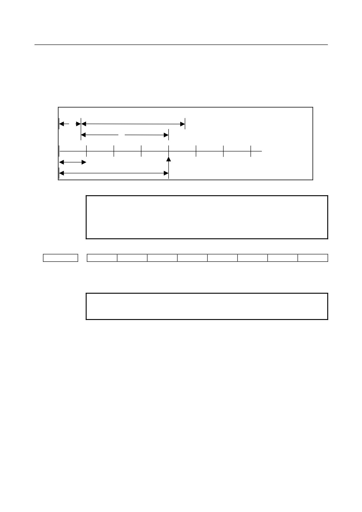
The amount of pulses exceeding the rapid traverse rate can be saved by CNC as B. And
amount of pulses B will be exported as pulses C.
A:amount of pulses corresponds to value of Rapid Traverse Rate.
B:amount of pulses accumulated in CNC.
B
C:amount of pulses the same as B.
Rapid Traverse Rate
A
C
t
Amount of pulses exported by CNC in Manual Handle Feed
Amount of pulses B is calculated in 2 cases as following:
In case of
1)
Parameter No.7117 = 0
The feedrate is clamped at the Rapid Traverse Rate and generated pulses exceeding
the Rapid Traverse Rate are ignored (B=0)
In case of
2)
Parameter No.7117 > 0
The feedrate is clamped as the Rapid Traverse Rate, but the pulses exceeding the
Rapid Traverse Rate is not ignored. Amount of pulses accumulated in CNC is
calculated as following. (Although stopping the rotation of manual pulse generator,
if there is pulses accumulated in CNC, it will be exported and the tool will move as
long as amount of it.)
- 886 -
B-64304EN/02
APPENDIX
A.PARAMETERS
Magnification set by MP1㧘MP2<Gn019.4,.5> is m, value of parameter No.7117 is
n.
n < m: Clamping is set performed at value of parameter No.7117.
n ≥ m: Amount A+B, showed in figure, which’s value is multiple of m and small
than n. As a result, clamping is performed as an integral multiple of the selected
magnification.
A: amount of pulses the same as Rapid Traverse Rate.
n
A
B: amount of pulses saved in CNC.
B
k : integer number
m
A+B=k⋅m
pulses over (k⋅m) will be ignored
Amount of pulses exceeding the Rapid Traverse Rate (n ≥ m)
NOTE
Due to change of mode, clamping can be performed not as an
integral multiple of the selected magnification.
The distance the tool moves may not match the graduations on the
manual pulse generator.
#7
#6
#5
#4
#3
#2
#1
#0
7200
OP7
OP6
OP5
OP4
OP3
OP2
OP1
[Input type] Parameter input
[Data type] Bit path
NOTE
When at least one of these parameters is set, the power must be
turned off before operation is continued.
#0 OP1 Mode selection on software operator's panel
0: Not performed
1: Performed
#1 OP2 JOG feed axis select and manual rapid traverse select on software operator's panel
0: Not performed
1: Performed
#2 OP3 Manual pulse generator's axis select and manual pulse generator's magnification select on
software operator's panel
0: Not performed
1: Performed
#3 OP4 JOG feedrate override select, feedrate override select, and rapid traverse override select
on software operator's panel
0: Not performed
1: Performed
- 887 -
A.PARAMETERS
APPENDIX
B-64304EN/02
#4
OP5 Optional block skip select, single block select, machine lock select, and dry run select on
software operator's panel
0: Not performed
1: Performed
#5
OP6 Protect key on software operator's panel
0: Not performed
1: Performed
#6
OP7 Feed hold on software operator's panel
0: Not performed
1: Performed
7210
Jog-movement axis and its direction on software operator's panel “↑”
7211
Jog-movement axis and its direction on software operator's panel “↓”
7212
Jog-movement axis and its direction on software operator's panel “→”
7213
Jog-movement axis and its direction on software operator's panel “←”
7214
Jog-movement axis and its direction on software operator's panel “
”
7215
Jog-movement axis and its direction on software operator's panel “
”
7216
Jog-movement axis and its direction on software operator's panel “
”
7217
Jog-movement axis and its direction on software operator's panel “
”
[Input type] Parameter input
[Data type] Byte path
[Valid data range] 0 to 8
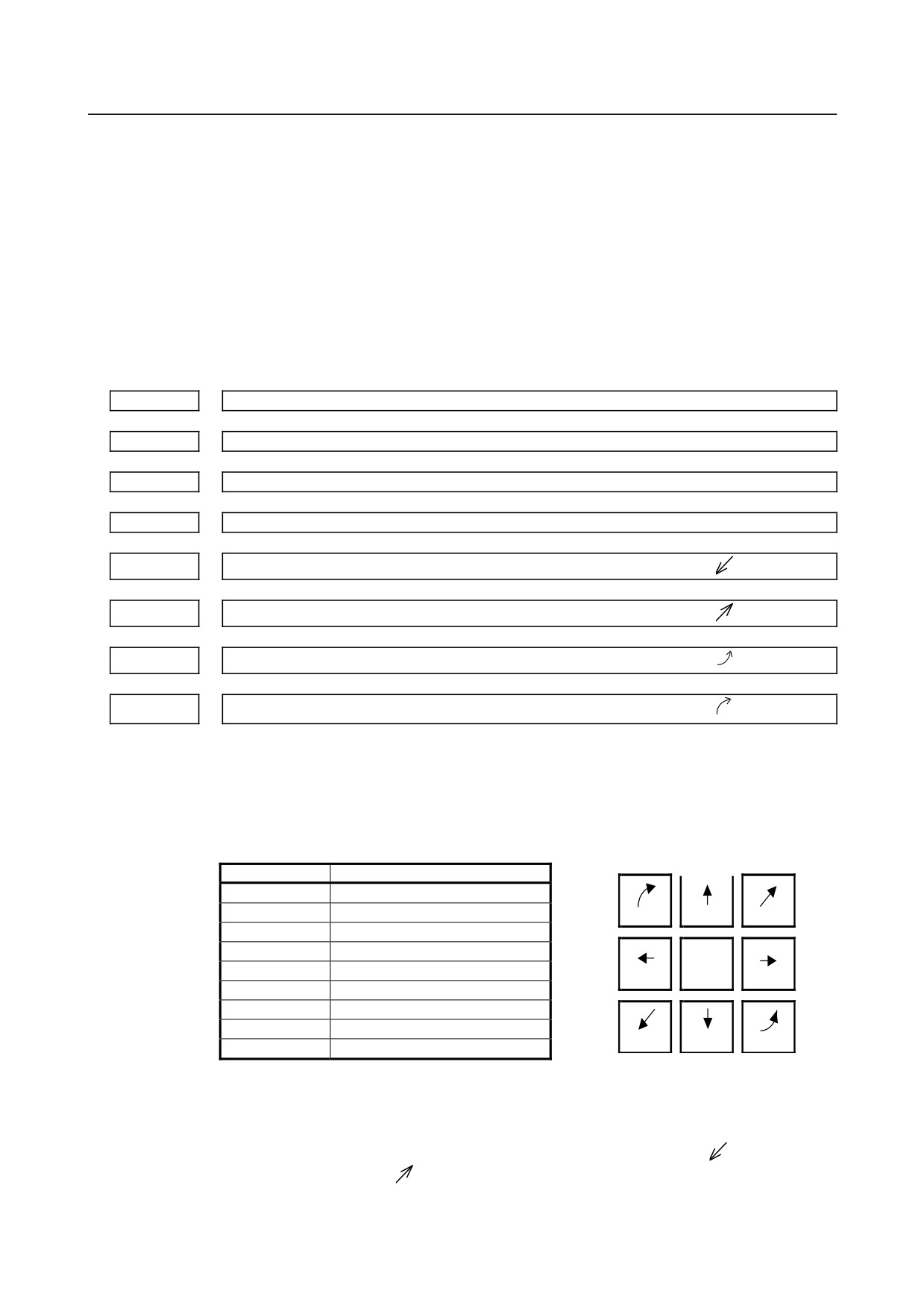
On software operator's panel, set a feed axis corresponding to an arrow key on the MDI
panel when jog feed is performed.
Arrow keys on MDI panel
Setting value
Feed axis and direction
0
Not moved
1
First axis, positive direction
7
8
9
2
First axis, negative direction
3
Second axis, positive direction
4
Second axis, negative direction
4
5
6
5
Third axis, positive direction
6
Third axis, negative direction
7
Fourth axis, positive direction
1
2
3
8
Fourth axis, negative direction
[Example] Under X, Y, and Z axis configuration, to set arrow keys to feed the axes in the direction
specified as follows, set the parameters to the values given below. [8↑] to the positive
direction of the Z axis, [2↓] to the negative direction of the Z axis, [6→] to the positive
direction of the X axis [4←] to the negative direction of the X axis, [1
] to the positive
direction of the Y axis, [9
] to the negative direction of the Y axis
- 888 -
B-64304EN/02
APPENDIX
A.PARAMETERS
Parameter No.7210 = 5 (Z axis, positive direction)
Parameter No.7211 = 6 (Z axis, negative direction)
Parameter No.7212 = 1 (X axis, positive direction)
Parameter No.7213 = 2 (X axis, negative direction)
Parameter No.7214 = 3 (Y axis, positive direction)
Parameter No.7215 = 4 (Y axis, negative direction)
Parameter No.7216 = 0 (Not used)
Parameter No.7217 = 0 (Not used)
#7
#6
#5
#4
#3
#2
#1
#0
7300
MOU
MOA
[Input type] Parameter input
[Data type] Bit path
#6 MOA In program restart operation, before movement to a machining restart point:
0: The last M, S, T, and B codes are output.
1: All M codes and the last S, T, and B codes are output.
This parameter is enabled when the MOU parameter is set to 1.
#7 MOU In program restart operation, before movement to a machining restart point after restart
block search:
0: The M, S, T, and B codes are not output.
1: The last M, S, T, and B codes are output.
7310
Ordinal number of an axis along which a movement is made in dry run after program restart
[Input type] Setting input
[Data type] Byte axis
[Valid data range] 1 to Number of controlled axes
This parameter sets the ordinal number of an axis along which a movement is made in dry
run after the program is restarted.
#7
#6
#5
#4
#3
#2
#1
#0
PLZ
7600
[Input type] Parameter input
[Data type] Bit path
#7 PLZ Reference position return based on a G28 command on the tool rotation axis for polygon
turning is:
0: Performed in the same sequence as manual reference position return.
1: Performed by positioning using the rapid traverse rate.
The synchronous axis returns to the reference position in the same sequence as the
manual reference position return when no return-to-reference position is performed after
the power is turned on.
- 889 -

A.PARAMETERS
APPENDIX
B-64304EN/02
Control axis number of tool rotation axis for polygon turning
7610
NOTE
When this parameter is set, the power must be turned off before
operation is continued.
[Input type] Parameter input
[Data type] Byte path
[Valid data range] 1 to number of controlled axes
This parameter sets the control axis number of a rotation tool axis used for polygon
turning.
However, when a G51.2 command is executed by setting 0 in this parameter, operation
stops with the alarm (PS0314).
Master axis in spindle-spindle polygon turning
7640
[Input type] Parameter input
[Data type] Byte path
[Valid data range] 0 to Maximum number of controlled axes (Within a path)
This parameter sets the master axis in spindle-spindle polygon turning.
NOTE
1 Spindle-spindle polygon turning is enabled only for serial spindles.
2 When any one of parameter No. 7640 and No. 7641 is set to 0,
polygon turning is performed using the first spindle (master axis)
and the second spindle (polygon synchronous axis) in the path to
which the parameter belongs.
3 When an axis other than the first serial spindle is selected as the
master axis, multi-spindle control is required to execute an S
command for the master axis.
4 When the PMC window function or G10 command is used to
rewrite this parameter, rewrite this parameter before the block
specifying the spindle-spindle polygon command G51.2. When the
PMC window function is used to rewrite this parameter in the block
immediately before G51.2, specify the rewriting of this parameter
by using an M code (parameter No. 3411 and up) without buffering.
Polygon synchronous axis in spindle-spindle polygon turning
7641
[Input type] Parameter input
[Data type] Byte path
[Valid data range] 0 to Maximum number of controlled axes (Within a path)
This parameter sets the polygon synchronous (slave) axis in spindle-spindle polygon
turning.
- 890 -

B-64304EN/02
APPENDIX
A.PARAMETERS
NOTE
1 Spindle-spindle polygon turning is enabled only for serial spindles.
2 When any one of parameter No. 7640 and No. 7641 is set to 0,
polygon turning is performed using the first spindle (master axis)
and the second spindle (polygon synchronous axis) in the path to
which the parameter belongs.
3 When an axis other than the first serial spindle is selected as the
master axis, multi-spindle control is required to execute an S
command for the master axis.
4 When the PMC window function or G10 command is used to
rewrite this parameter, rewrite this parameter before the block
specifying the spindle-spindle polygon command G51.2. When the
PMC window function is used to rewrite this parameter in the block
immediately before G51.2, specify the rewriting of this parameter
by using an M code (parameter No. 3411 and up) without buffering.
Master axis in spindle-spindle polygon turning (spindle number common to the system)
7642
[Input type] Parameter input
[Data type] Byte path
[Valid data range] 0 to Maximum number of controlled axes (Common to the system)
This parameter sets the master axis in spindle-spindle polygon turning.
NOTE
1 Spindle-spindle polygon turning is enabled only for serial spindles.
2 This parameter is invalid if either parameter No. 7642 or No.7643 is
set to 0. In this case, the settings of parameter No. 7640 and
No.7641 are valid.
3 When an axis other than the first serial spindle is selected as the
master axis, multi-spindle control is required to execute an S
command for the master axis.
4 When the PMC window function or G10 command is used to
rewrite this parameter, rewrite this parameter before the block
specifying the spindle-spindle polygon command G51.2. When the
PMC window function is used to rewrite this parameter in the block
immediately before G51.2, specify the rewriting of this parameter
by using an M code (parameter No. 3411 and up) without buffering.
5 A spindle number common to the system is to be set in this
parameter. When using this parameter, set 0 in parameter No.
7640 and No. 7641.
Polygon synchronous axis in spindle-spindle polygon turning (spindle number common to the system)
7643
[Input type] Parameter input
[Data type] Byte path
[Valid data range] 0 to Maximum number of controlled axes (Common to the system)
This parameter sets the polygon synchronous (slave) axis in spindle-spindle polygon
turning.
- 891 -

A.PARAMETERS
APPENDIX
B-64304EN/02
NOTE
1 Spindle-spindle polygon turning is enabled only for serial spindles.
2 This parameter is invalid if either parameter No. 7642 or No.7643 is
set to 0. In this case, the settings of parameter No. 7640 and
No.7641 are valid.
3 When an axis other than the first serial spindle is selected as the
master axis, multi-spindle control is required to execute an S
command for the master axis.
4 When the PMC window function or G10 command is used to
rewrite this parameter, rewrite this parameter before the block
specifying the spindle-spindle polygon command G51.2. When the
PMC window function is used to rewrite this parameter in the block
immediately before G51.2, specify the rewriting of this parameter
by using an M code (parameter No. 3411 and up) without buffering.
5 A spindle number common to the system is to be set in this
parameter. When using this parameter, set 0 in parameter No.
7640 and No. 7641.
#7
#6
#5
#4
#3
#2
#1
#0
7700
HDR
HBR
[Input type] Parameter input
[Data type] Bit path
#0 HBR When the electronic gear box (EGB) function is used, performing a reset:
0: Cancels the synchronous mode (G81).
1: Does not cancel the synchronous mode. The mode is canceled only by the G80
command.
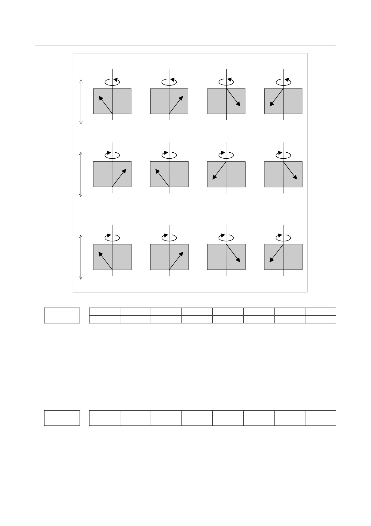
#2 HDR Direction of helical gear compensation (usually, set 1.)
(Example) To cut a left-twisted helical gear when the direction of rotation about the
C-axis is the negative (-) direction:
0: Set a negative (-) value in P.
1: Set a positive (+) value in P.
- 892 -
B-64304EN/02
APPENDIX
A.PARAMETERS
When HDR = 1
(a)
(b)
(c)
(d)
+Z
+C
+C
+C
+C
C : +, Z : +, P : +
C : +, Z : +, P : -
C : +, Z : -, P : +
C : +, Z : -, P : -
Compensation direction:+
Compensation direction:-
Compensation direction:-
Compensation direction:+
-Z
(e)
(f)
(g)
(h)
+Z
-C
-C
-C
-C
C : -, Z : +, P : +
C : -, Z : +, P : -
C : -, Z : -, P : +
C : -, Z : -, P : -
Compensation direction:+
Compensation direction:-
-Z C : Compensation direction:-Compensation direction:+
When HDR = 0 ((a), (b), (c), and (d) are the same as when HDR = 1)
(e)
(f)
(g)
(h)
+Z
-C
-C
-C
-C
C : -, Z : +, P : +
C : -, Z : +, P : -
C : -, Z : -, P : +
C : -, Z : -, P : -
Compensation direction:-
Compensation direction:-
Compensation direction:+
-Z Compensation direction:+
#7
#6
#5
#4
#3
#2
#1
#0
7701
LZR
[Input type] Parameter input
[Data type] Bit path
#3 LZR When L (number of hob threads) = 0 is specified at the start of EGB synchronization
(G81):
0: Synchronization is started, assuming that L = 1 is specified.
1: Synchronization is not started, assuming that L = 0 is specified. However, helical
gear compensation is performed.
#7
#6
#5
#4
#3
#2
#1
#0
7702
ART
TDP
[Input type] Parameter input
[Data type] Bit path
#0 TDP The specifiable number of teeth, T, of the electronic gear box (G81) is:
0:
1 to 1000
1:
0.1 to 100 (1/10 of a specified value)
- 893 -
A.PARAMETERS
APPENDIX
B-64304EN/02
NOTE
In either case, a value from 1 to 1000 can be specified.
#3 ART The retract function executed when an alarm is issued is:
0: Disabled.
1: Enabled.
When an alarm is issued, a retract operation is performed with a set feedrate and travel
distance (parameter Nos. 7740 and 7741).
NOTE
If a servo alarm is issued for other than the axis along which a
retract operation is performed, the servo activating current is
maintained until the retract operation is completed.
#7
#6
#5
#4
#3
#2
#1
#0
7703
ARO
ARE
ERV
[Input type] Parameter input
[Data type] Bit path
#0 ERV During EGB synchronization (G81), feed per revolution is performed for:
0: Feedback pulses.
1: Pulses converted to the speed for the workpiece axis.
#1 ARE In the retract function by an alarm, retract operation is:
0: Performed during EGB synchronization or automatic operation (automatic operation
signal = 1).
1: Determined by the setting of parameter ARO.
#2
ARO The retract function executed when an alarm is issued retracts the tool during:
0: EGB synchronization.
1: EGB synchronization and automatic operation (automatic operation signal OP = 1).
NOTE
This parameter is valid when bit 1 (ARE) of parameter No. 7703 is
set to 1.
The following table lists the parameter settings and corresponding operation.
ARE
ARO
Operation
1
0
During EGB synchronization
1
1
During EGB synchronization and automatic operation
0
0
During EGB synchronization or automatic operation
0
1
NOTE
Parameters ARE and ARO are valid when bit 3 (ART) of parameter
No. 7702 is set to 1 (when the retract function executed when an
alarm is issued ).
- 894 -
B-64304EN/02
APPENDIX
A.PARAMETERS
#7
#6
#5
#4
#3
#2
#1
#0
7731
ECN
EFX
[Input type] Parameter input
[Data type] Bit path
#0 EFX As the EGB command:
0: G80 and G81 are used.
1: G80.4 and G81.4 are used.
NOTE
When this parameter is set to 0, no drilling canned cycle can be
used.
#3 ECN During EGB synchronization:
0: G81 cannot be specified again.
(An alarm (PS1595) occurs.)
1: G81 can be specified.
7740
Feedrate during retraction
[Input type] Parameter input
[Data type] Real axis
[Unit of data] mm/min, inch/min, degree/min (machine unit)
[Min. unit of data] Depend on the increment system of the applied axis
[Valid data range] Refer to the standard parameter setting table (C)
(When the increment system is IS-B, 0.0 to +999000.0)
This parameter sets the feedrate during retraction for each axis.
7772
Number of position detector pulses per rotation about the tool axis
[Input type] Parameter input
[Data type] 2-word path
[Valid data range] 1 to 999999999
This parameter sets the number of pulses per rotation about the tool axis (on the spindle
side), for the position detector.
For an A/B phase detector, set this parameter with four pulses equaling one A/B phase
cycle.
NOTE
Specify the number of feedback pulses per rotation about the tool
axis for the position detector, considering the gear ratio with
respect to the position coder.
7773
Number of position detector pulses per rotation about the workpiece axis
[Input type] Parameter input
[Data type] 2-word path
[Valid data range] 1 to 999999999
This parameter sets the number of pulses per rotation about the workpiece axis (on the
slave side), for the position detector.
Set the number of pulses output by the detection unit.
- 895 -
A.PARAMETERS
APPENDIX
B-64304EN/02
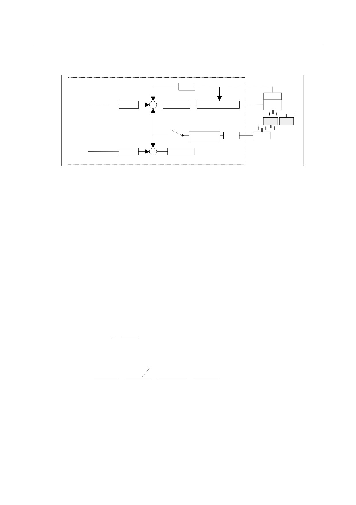
Set parameters Nos. 7772 and 7773 when using the G81 EGB synchronization command.
[Example 1] When the EGB master axis is the spindle and the EGB slave axis is the C-axis
CNC
×FFG
α p/rev
n/m
Command
Detector
pulses
Slave axis
×CMR
Error counter
Speed/current control
Motor
Gear ratio
Least command increment
A
0.001deg
Detection unit
Gear
Spindle
C-axis
ratio B
Synchronization
×FFG
Detector
Synchronization
factor
N/M
β p/rev
switch
Follow-up
Dummy axis
×CMR
Error counter
Gear ratio of the spindle to the detector B:
1/1 (The spindle and detector are directly connected to each other.)
Number of detector pulses per spindle rotation β: 80,000 pulses/rev
(Calculated for four pulses for one A/B phase cycle)
FFG N/M of the EGB dummy axis:
1/1
Gear ratio of the C-axis A:
1/36 (One rotation about the C-axis to 36 motor rotations)
Number of detector pulses per C-axis rotation α: 1,000,000 pulses/rev
C-axis CMR:
1
C-axis FFG n/m:
1/100
In this case, the number of pulses per spindle rotation is:
80000 × 1/1 = 80000
Therefore, set 80000 for parameter No. 7772.
The number of pulses per C-axis rotation in the detection unit is:
1000000 ÷ 1/36 × 1/100 = 360000
Therefore, set 360000 for parameter No. 7773.
[Example 2] When the gear ratio of the spindle to the detector B is 2/3 for the above example (When
the detector rotates twice for three spindle rotations)
In this case, the number of pulses per spindle rotation is:
2
160000
80000 ×
=
3
3
160000 cannot be divided by 3 without a remainder. In this case, change the setting of
parameter No. 7773 so that the ratio of the settings of parameters Nos. 7772 and 7773
indicates the value you want to set.
160000
No.7772
3
160000
160000
=
=
=
No.7773
360000
360000
×
3
1080000
Therefore, set 160000 for parameter No. 7772 and 1080000 for parameter No. 7773.
As described above, all the settings of parameters Nos. 7772 and 7773 have to do is to
indicate the ratio correctly. So, you can reduce the fraction indicated by the settings. For
example, you may set 16 for parameter No. 7772 and 108 for parameter No. 7773 for this
case.
- 896 -
B-64304EN/02
APPENDIX
A.PARAMETERS
#7
#6
#5
#4
#3
#2
#1
#0
8001
RDE
OVE
MLE
[Input type] Parameter input
[Data type] Bit path
#0 MLE Whether all axis machine lock signal MLK is valid for PMC-controlled axes
0: Valid
1: Invalid
The axis-by-axis machine lock signal MLKx depends on the setting of bit 1 of parameter
No. 8006.
#2 OVE Signals related to dry run and override used in PMC axis control
0: Same signals as those used for the CNC
1: Signals specific to the PMC
The signals used depend on the settings of these parameter bits as indicated below.
No.8001#2=0
No.8001#2=1
Signals
(same signals as those used
(signals specific to the PMC)
for the CNC)
Feedrate override
*FV0 to *FV7
G012
*EFOV0 to *EFOV7 G151
signals
Override cancellation
OVC
G006.
EOVC
G150.5
signal
Rapid traverse override
ROV1,2
G014.0, .1
EROV1,2
G150.0, .1
signals
Dry run signal
DRN
G46.7
EDRN
G150.7
Rapid traverse selection
RT
G19.7
ERT
G150.6
signal
(The signal addresses at PMC selection time are for the group A.)
#3 RDE Whether dry run is valid for rapid traverse in PMC axis control
0: Invalid
1: Valid
#7
#6
#5
#4
#3
#2
#1
#0
8002
FR2
FR1
PF2
PF1
F10
RPD
[Input type] Parameter input
[Data type] Bit path
#0 RPD Rapid traverse rate for PMC-controlled axes
0: Feedrate specified with parameter No.1420
1: Feedrate specified with the feedrate data in an axis control command by PMC
#3 F10 Least increment for the feedrate for cutting feed (per minute) in PMC axis control
The following settings are applied when bit 4 (PF1) of parameter No. 8002 is set to 0 and
bit 5 (PF2) of parameter No. 8002 is set to 0.
F10
IS-A
IS-B
IS-C
Millimeter input
0
10
1
0.1
(mm/min)
1
100
10
1
Inch input
0
0.1
0.01
0.001
(inch/min)
1
1
0.1
0.01
- 897 -
A.PARAMETERS
APPENDIX
B-64304EN/02
#4 PF1
#5 PF2 Set the feedrate unit of cutting feedrate (feed per minute) for an axis controlled by the
PMC.
Bit 5 (PF2) of parameter No. 8002
Bit 4 (PF1) of parameter No. 8002
Feedrate unit
0
0
1 / 1
0
1
1 / 10
1
0
1 / 100
1
1
1 / 1000
#6 FR1
#7 FR2 Set the feedrate unit for cutting feedrate (feed per rotation) for an axis controlled by the
PMC.
Bit 7 (FR2) of parameter
Bit 6 (FR1) of parameter
Millimeter input
Inch input
No. 8002
No. 8002
(mm/rev)
(inch/rev)
0
0
0.0001
0.000001
1
1
0
1
0.001
0.00001
1
0
0.01
0.0001
#7
#6
#5
#4
#3
#2
#1
#0
8004
NCI
[Input type] Parameter input
[Data type] Bit path
#6 NCI In axis control by the PMC, a position check at the time of deceleration is:
0: Performed.
1: Not performed.
#7
#6
#5
#4
#3
#2
#1
#0
8005
EDC
[Input type] Setting input
[Data type] Bit path
#0 EDC In axis control by the PMC, an external deceleration function is:
0: Disabled.
1: Enabled.
#7
#6
#5
#4
#3
#2
#1
#0
8006
EZR
EFD
[Input type] Parameter input
[Data type] Bit path
#4 EFD When cutting feed (feed per minute) is used in PMC axis control, the specification unit of
feedrate data is:
0: Unchanged (1 times).
1:
100 times greater.
NOTE
When this parameter is set to 1, bit 3 (F10) of parameter No. 8002
is invalid.
- 898 -
B-64304EN/02
APPENDIX
A.PARAMETERS
#6 EZR In PMC axis control, bit 0 (ZRNx) of parameter No. 1005 is:
0: Invalid.
With a PMC controlled axis, the alarm (PS0224) is not issued.
1: Valid.
A reference position return state check is made on a PMC controlled axis as with an
NC axis according to the setting of bit 0 (ZRNx) of parameter No. 1005.
#7
#6
#5
#4
#3
#2
#1
#0
8008
EMRx
[Input type] Parameter input
[Data type] Bit axis
#0 EMRx When a PMC axis control command is issued in mirror image state, the mirror image is:
0: Not considered.
1: Considered.
This parameter is valid in the mirror image mode set with the mirror image signals MI1 to
MI5 <G106.0 to 4> set to 1 or bit 0 (MIRx) of parameter No. 12 set to 1.
If a movement is made along the same axis by doubly specifying a command with the
CNC and PMC axis control when this parameter is set to 0, and the mirror image mode is
set, a coordinate shift can occur afterwards. So, do not attempt to make such a movement.
8010
Selection of the DI/DO group for each axis controlled by the PMC
[Input type] Parameter input
[Data type] Byte axis
[Valid data range] T series: 1 to 4 (at 1-path control), 1 to 8 (at 2-path control)
M series: 1 to 4
Specify the DI/DO group to be used to specify a command for each PMC-controlled axis.
P8010
Description
1
Uses path 1 DI/DO group A (G142 to G153)
2
Uses path 1 DI/DO group B (G154 to G165)
3
Uses path 1 DI/DO group C (G166 to G177)
4
Uses path 1 DI/DO group D (G178 to G189)
5
Uses path 2 DI/DO group A (G1142 to G1153)
6
Uses path 2 DI/DO group B (G1154 to G1165)
7
Uses path 2 DI/DO group C (G1166 to G1177)
8
Uses path 2 DI/DO group D (G1178 to G1189)
NOTE
Use path 1 DI/DO (1 to 4) for the axes controlled by path 1.
Use path 2 DI/DO (5 to 8) for the axes controlled by path 2.
Time constant for exponential acceleration/deceleration in cutting feed or continuous feed under PMC
8030
axis control
[Input type] Parameter input
[Data type] 2-word axis
[Unit of data] msec
[Valid data range] 0 to 4000
For each axis, this parameter sets a time constant for exponential
acceleration/deceleration in cutting feed or continuous feed under PMC axis control.
- 899 -
A.PARAMETERS
APPENDIX
B-64304EN/02
NOTE
When 0 is set in this parameter, the value set in parameter No.
1622 is used.
The value set in parameter No. 1622 is used also for linear
acceleration/deceleration after cutting interpolation.
#7
#6
#5
#4
#3
#2
#1
#0
MWT
8103
[Input type] Parameter input
[Data type] Bit
NOTE
When this parameter is set, the power must be turned off before
operation is continued.
#0 MWT As the signal interface for the waiting M code:
0: The path individual signal interface is used.
1: The path common signal interface is used.
This parameter can be selected only when 2-path control is used.
NOTE
When this parameter is set to 1, the operation equivalent to that of
the FS0i-C is assumed.
Waiting M code range (minimum value)
8110
Waiting M code range (maximum value)
8111
[Input type] Parameter input
[Data type] 2-word
[Valid data range] 0, 100 to 99999999
A range of M code values can be set by specifying a minimum waiting M coder value
(parameter No. 8110) and a maximum waiting M code value (parameter No. 8111).
(parameter No. 8110) ≤ (waiting M code) ≤ (parameter No. 8111)
Set 0 in these parameters when the waiting M code is not used.
8130
Number of controlled axes
NOTE
When this parameter is set, the power must be turned off before
operation is continued.
[Input type] Parameter input
[Data type] Byte path
[Valid data range] 1 to Maximum number of controlled axes
This parameter sets the number of axes for each path.
- 900 -
B-64304EN/02
APPENDIX
A.PARAMETERS
NOTE
When spindle control with servo motor is enabled, set the number
of axes including this axis for the axes with a spindle controlled axis
with servo motor.
#7
#6
#5
#4
#3
#2
#1
#0
EDC
HPG
8131
AOV
EDC
F1D
HPG
NOTE
When at least one of these parameters is set, the power must be
turned off before operation is continued.
[Input type] Parameter input
[Data type] Bit
#0 HPG Manual handle feed is:
0: Not Used.
1: Used.
#1 F1D One-digit F code feed is:
0: Not Used.
1: Used.
#2 EDC External deceleration is:
0: Not Used.
1: Used.
#3 AOV Automatic corner override is:
0: Not Used.
1: Used.
#7
#6
#5
#4
#3
#2
#1
#0
BCD
YOF
TLF
8132
SCL
SPK
IXC
BCD
TLF
NOTE
When at least one of these parameters is set, the power must be
turned off before operation is continued.
[Input type] Parameter input
[Data type] Bit
#0 TLF Tool life management is:
0: Not Used.
1: Used.
#1 YOF Y-axis offset is:
0: Not Used.
1: Used.
- 901 -
A.PARAMETERS
APPENDIX
B-64304EN/02
#2 BCD Second auxiliary function is:
0: Not Used.
1: Used.
#3 IXC Index table indexing is:
0: Not Used.
1: Used.
NOTE
When enabling the index table indexing function, set bit 0 (ITI) of
parameter No. 5501 to 0 in addition to this parameter. The index
table indexing function is enabled only when both ITI and IXC are
enabled.
#4 SPK Small diameter peck drilling cycle is:
0: Not Used.
1: Used.
#5 SCL Scaling is:
0: Not Used.
1: Used.
#7
#6
#5
#4
#3
#2
#1
#0
SPG
SSN
SYC
MSP
SCS
AXC
SSC
8133
SSN
SYC
MSP
SCS
SSC
NOTE
When at least one of these parameters is set, the power must be
turned off before operation is continued.
[Input type] Parameter input
[Data type] Bit
#0 SSC Constant surface speed control is:
0: Not Used.
1: Used.
#1 AXC Spindle positioning is:
0: Not Used.
1: Used.
NOTE
1 Be sure to set 1 in bit 1 (AXC) of parameter No.8133 and 0 in bit 2
(SCS) of parameter No.8133 to use the spindle positioning
function.
2 Both serial spindle Cs contour control function and spindle
positioning function cannot be made effective at the same time.
If both are specified as AXC=1 and SCS=1, both functions become
invalid.
Therefore, when a negative value is set in parameter No.1023 with
above specification, alarm (SV1026) is generated.
- 902 -

B-64304EN/02
APPENDIX
A.PARAMETERS
NOTE
3 Be sure to set 0 in bit 1 (AXC) of parameter No.8133 and 1 in bit 2
(SCS) of parameter No.8133 to use the serial spindle Cs contour
control function.
#2 SCS Cs contour control is:
0: Not Used.
1: Used.
NOTE
1 Be sure to set 0 in bit 1 (AXC) of parameter No.8133 and 1 in bit 2
(SCS) of parameter No.8133 to use the serial spindle Cs contour
control function.
2 Both serial spindle Cs contour control function and spindle
positioning function cannot be made effective at the same time.
If both are specified as AXC=1 and SCS=1, both functions become
invalid.
Therefore, when a negative value is set in parameter No.1023 with
above specification, alarm (SV1026) is generated.
3 Be sure to set 1 in bit 1 (AXC) of parameter No.8133 and 0 in bit 2
(SCS) of parameter No.8133 to use the spindle positioning
function.
#3 MSP Multi-spindle is:
0: Not Used.
1: Used.
#4 SYC Spindle synchronization is:
0: Not Used.
1: Used.
#5 SSN Spindle serial output is:
0: Used.
1: Not Used.
Set this parameter as shown below depending on the spindle configuration.
Spindle configuration
Parameter SSN
When all spindles in the entire system are serial spindles
0
When serial spindles and analog spindles are mixed in the entire system
0
When all spindles in the entire system are analog spindles
1
#6 SPG Polygon turning with two spindles is:
0: Not Used.
1: Used.
NOTE
Be sure to invalidate the polygon turning with two spindles by this
parameter when polygon turning is used. If the polygon turning is
performed when 1 is set in this parameter, the alarm is issued.
- 903 -
A.PARAMETERS
APPENDIX
B-64304EN/02
#7
#6
#5
#4
#3
#2
#1
#0
NCT
NBG
NGR
CCR
BAR
IAP
8134
NCT
NBG
NGR
BAR
IAP
NOTE
When at least one of these parameters is set, the power must be
turned off before operation is continued.
[Input type] Parameter input
[Data type] Bit
#0 IAP Conversational programming with graphic function is:
0: Not Used.
1: Used.
#1 BAR Chuck and tail stock barrier function (T series) is:
0: Not Used.
1: Used.
NOTE
1 The chuck and tail stock barrier function is provided only for the T
series.
2 When the chuck and tail stock barrier function is selected, stored
stroke limits 2 and 3 cannot be used.
That is, this parameter also specifies whether to use stored stroke limits 2 and 3 as shown
below.
BAR Stored stroke limits 2 and 3 are:
0: Used.
1: Not Used.
#2 CCR Chamfering / corner R is:
0: Not Used.
1: Used.
#3 NGR Graphic display is:
0: Used.
1: Not Used.
#6 NBG Background editing is:
0: Used.
1: Not Used.
#7 NCT Run hour and parts count display is:
0: Used.
1: Not Used.
- 904 -

B-64304EN/02
APPENDIX
A.PARAMETERS
#7
#6
#5
#4
#3
#2
#1
#0
8135
NPD
NCV
NMC
NOR
NRG
NSQ
NHI
NPE
NOTE
When at least one of these parameters is set, the power must be
turned off before operation is continued.
[Input type] Parameter input
[Data type] Bit
#0 NPE Stored pitch error compensation is:
0: Used.
1: Not Used.
#1 NHI Manual handle interruption is:
0: Used.
1: Not Used.
#2 NSQ Program restart is:
0: Used.
1: Not Used.
#3 NRG Rigid tapping is:
0: Used.
1: Not Used.
#4 NOR Spindle orientation is:
0: Used.
1: Not Used.
NOTE
This parameter is valid only when spindle serial output can be
used.
#5 NMC Custom macro is:
0: Used.
1: Not Used.
#6 NCV Addition of custom macro common variables is:
0: Used.
1: Not Used.
#7 NPD Pattern data input is:
0: Used.
1: Not Used.
- 905 -