FANUC Series 0i-MODEL D, Series 0i Mate-MODEL D. OPERATOR'S MANUAL - page 32
A.PARAMETERS
APPENDIX
B-64304EN/02
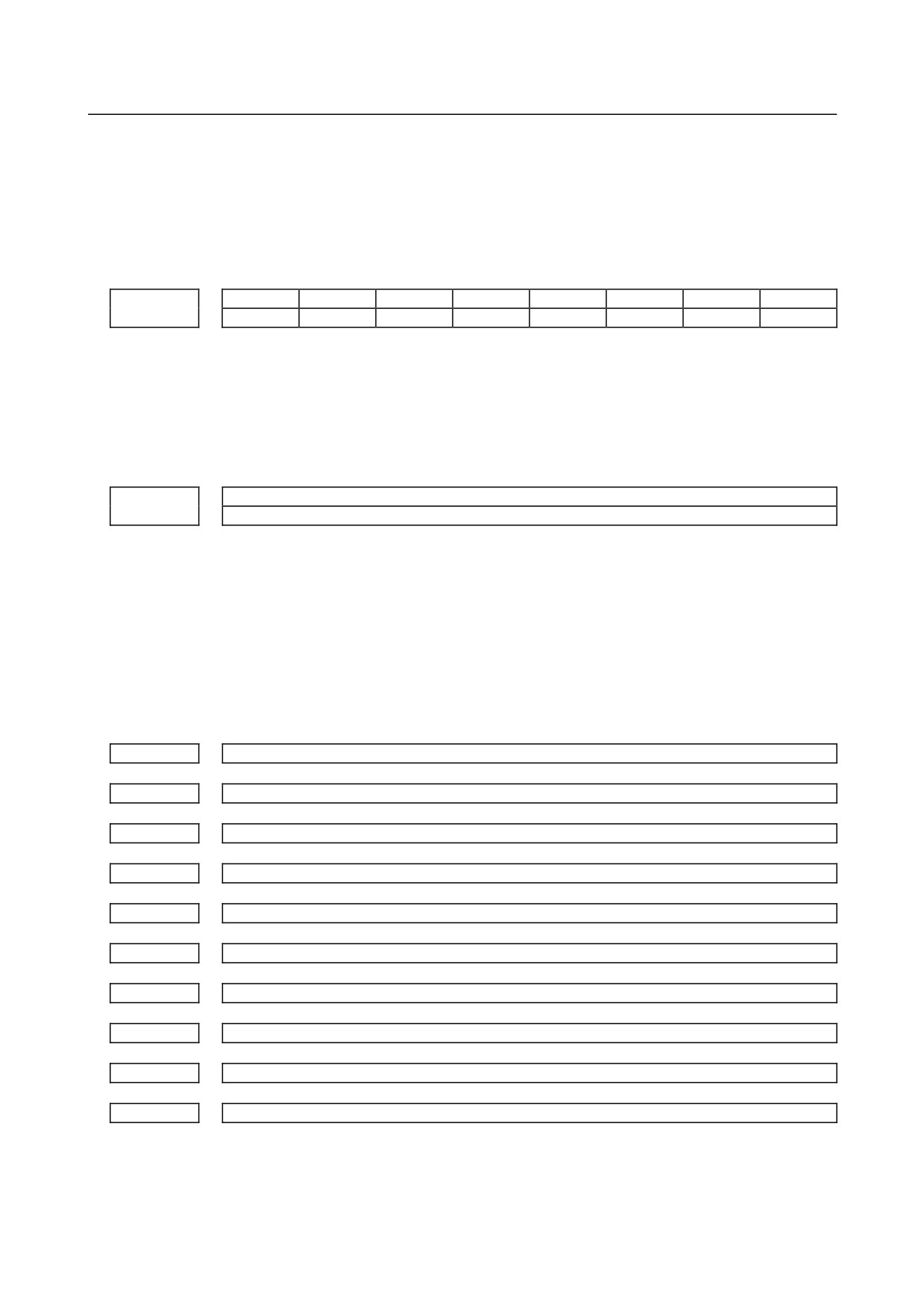
#7
#6
#5
#4
#3
#2
#1
#0
NCR
NGW
NDO
NOW
NOP
NWC
NWZ
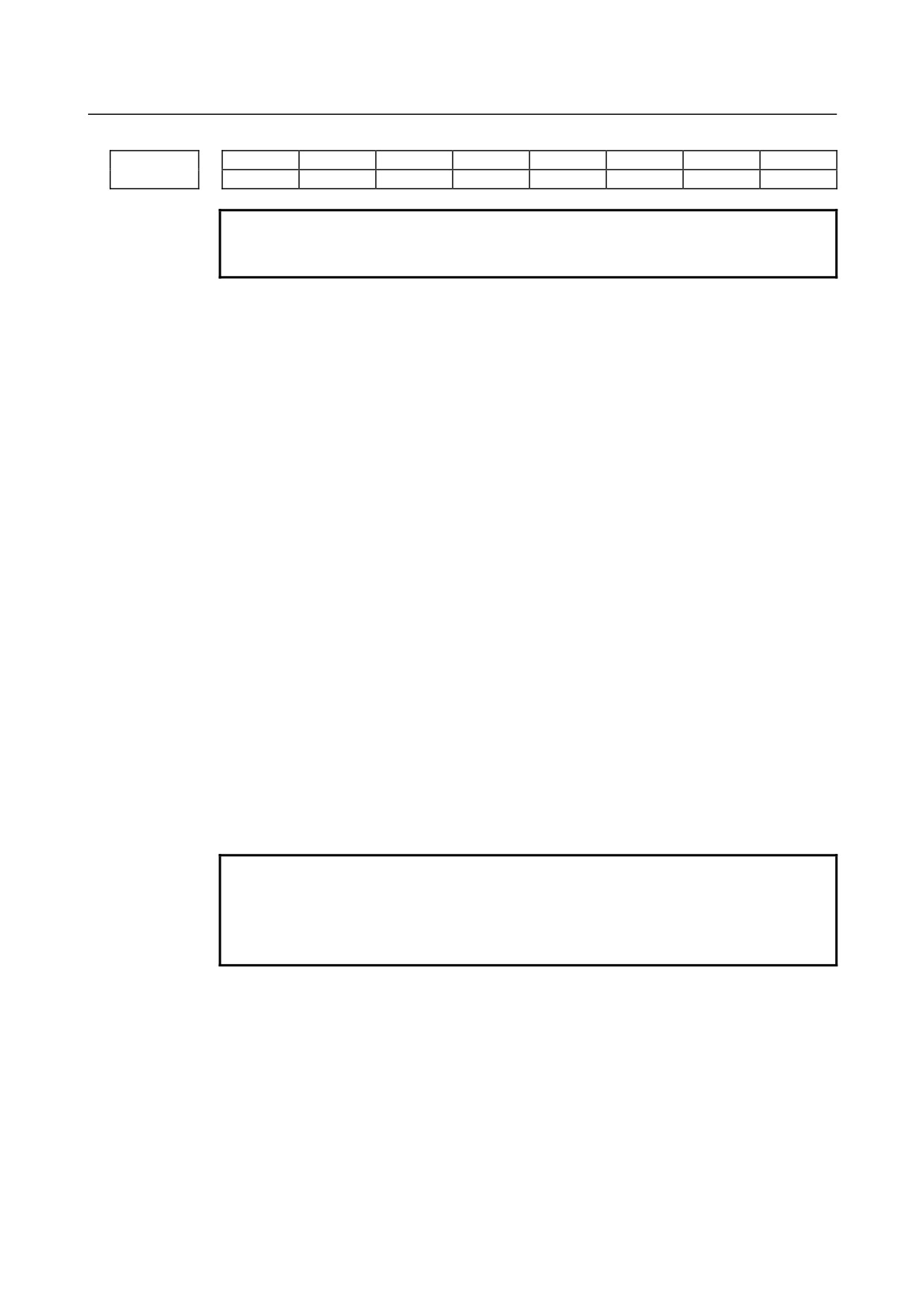
8136
NTL
NGW
NDO
NOW
NOP
NWN
NWC
NWZ
NOTE
When at least one of these parameters is set, the power must be
turned off before operation is continued.
[Input type] Parameter input
[Data type] Bit
#0 NWZ Workpiece coordinate system is:
0: Used.
1: Not Used.
#1 NWC Workpiece coordinate system preset is:
0: Used.
1: Not Used.
#2 NWN Addition of workpiece coordinate system pair (48 pairs) is:
0: Used.
1: Not Used.
#3 NOP Software operator's panel is:
0: Used.
1: Not Used.
#4 NOW Software operator's panel general purpose switch is:
0: Used.
1: Not Used.
#5 NDO Tool compensation count 400 (M series) or tool compensation count 64(T series 1-path
system) / 128(T series 2-path system) is:
0: Used.
1: Not Used.
NOTE
When the option of tool compensation count 99 (T series 1-path
system) / 200 (T series 2-path system) is added, this parameter
becomes invalid in T series. (Tool compensation count is fixed to
99 (T series 1-path system) / 200 (T series 2-path system).)
#6 NGW Tool offset memory C (M series) or tool geometry/wear compensation (T series) is:
0: Used.
1: Not Used.
#7 NTL Tool length measurement is:
NCR Tool nose radius compensation is:
0: Used.
1: Not Used.
- 906 -
B-64304EN/02
APPENDIX
A.PARAMETERS
#7
#6
#5
#4
#3
#2
#1
#0
NVC
8137
NOTE
When this parameter is set, the power must be turned off before
operation is continued.
[Input type] Parameter input
[Data type] Bit
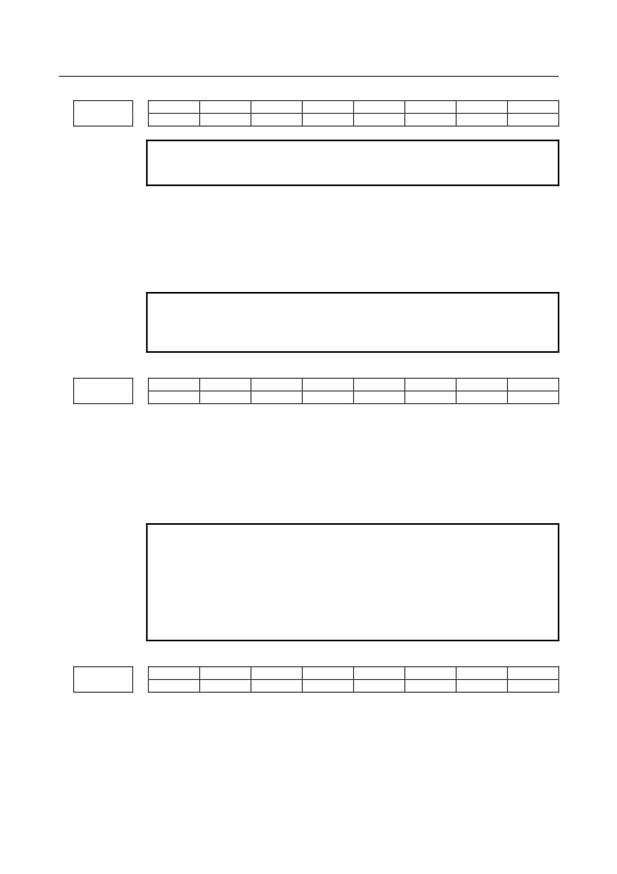
#0 NVC Balance cutting is:
0: Used.
1: Not Used.
NOTE
When balance cutting is used (this parameter is 0), the mirror
image of facing tool posts cannot be used. To use the mirror
image of facing tool posts, set this parameter to 1.
#7
#6
#5
#4
#3
#2
#1
#0
PKUx
8162
[Input type] Parameter input
[Data type] Bit axis
#2 PKUx In the parking state,
0: The absolute, relative, and machine coordinates are not updated.
1: The absolute and relative coordinates are updated. The machine coordinates are not
updated.
NOTE
1 With an axis for which polar coordinate interpolation is specified,
set this parameter to 1. If this parameter is set to 0, a coordinate
shift can occur when a single block stop or feed hold is performed
in the polar coordinate interpolation mode.
2 With an axis that is set to function as a synchronous master axis
and synchronous slave axis at the same time (with bit 1 (SYWx) of
parameter No. 8167), set this parameter to 1.
#7
#6
#5
#4
#3
#2
#1
#0
NUMx
8163
[Input type] Parameter input
[Data type] Bit axis
#7 NUMx When neither synchronous control nor composite control is applied, a move command for
the axis is:
0: Not disabled.
1: Disabled.
- 907 -
A.PARAMETERS
APPENDIX
B-64304EN/02
NOTE
If a move command is specified for an axis with NUMx set to 1
when neither synchronous control nor composite control is applied,
alarm PS0353 is issued.
Master axis with which an axis is synchronized under synchronous control
8180
[Input type] Parameter input
[Data type] Word axis
[Valid data range] 101, 102, 103, . . . , (path number)*100+(intra-path relative axis number) (101, 102,
103, . . . , 201, 202, 203, . . .)
This parameter sets the path number and intra-path relative axis number of the master axis
with which each axis is synchronized. When zero is specified, the axis does not become a
slave axis and is not synchronized with another axis. When an identical number is
specified in two or more parameters, one master axis has two or more slave axes.
Composite control axis of the other path in composite control for each axis
8183
[Input type] Parameter input
[Data type] Word axis
[Valid data range] 101, 102, 103, . . . , (path number)*100+(intra-path relative axis number) (101, 102,
103, . . . , 201, 202, 203, . . . )
This parameter sets with which axis each axis is to be placed under composite control.
When zero is specified, control of the axis is not replaced under composite control. An
identical number can be specified in two or more parameters, but composite control
cannot be exercised for all of them at a time.
NOTE
When using the conventional 2-path interface (bit 1 (MIX) of
parameter No. 8166 is 1, set this parameter on path 2. In this
case, use the composite control axis selection signal on path 1.
Master axis under superimposed control
8186
[Input type] Parameter input
[Data type] Word axis
[Valid data range] 101, 102, 103, . . . , (path number)*100+(intra-path relative axis number) (101, 102,
103, . . . , 201, 202, 203, . . . )
This parameter sets the path number and intra-path relative axis number of a
superimposed master axis for each axis when superimposed control is exercised. When
zero is specified, the axis does not become a slave axis under superimposed control and
the move pulse of another axis is not superimposed.
An identical number can be specified in two or more parameters to exercise superimposed
control simultaneously. This means that superimposed control with one master axis and
multiple slave axes is possible.
A slave axis may function as the master axis of another axis to allow three-generation
superimposed control: parent (master axis) - child (slave axis/master axis) - grandchild
(slave axis).
- 908 -
B-64304EN/02
APPENDIX
A.PARAMETERS
In this case, a movement along the child is made by its travel distance plus the travel
distance of the parent, and a movement along the grandchild is made by its travel distance
plus the travel distance of the child plus the travel distance of the parent.
Example of the relationship of parent (X1 of path 1) - child (X2 of path 2) - grandchild
(U2 of path 2):
The travel distance of X1 is superimposed on X2, and the travel distances of X1 and X2
are further superimposed on U2.
Parameter No. 8186x of path 2 = 101
Parameter No. 8186u of path 2 = 201
#7
#6
#5
#4
#3
#2
#1
#0
8200
AZR
AAC
[Input type] Parameter input
[Data type] Bit path
NOTE
When at least one of these parameters is set, the power must be
turned off before operation is continued.
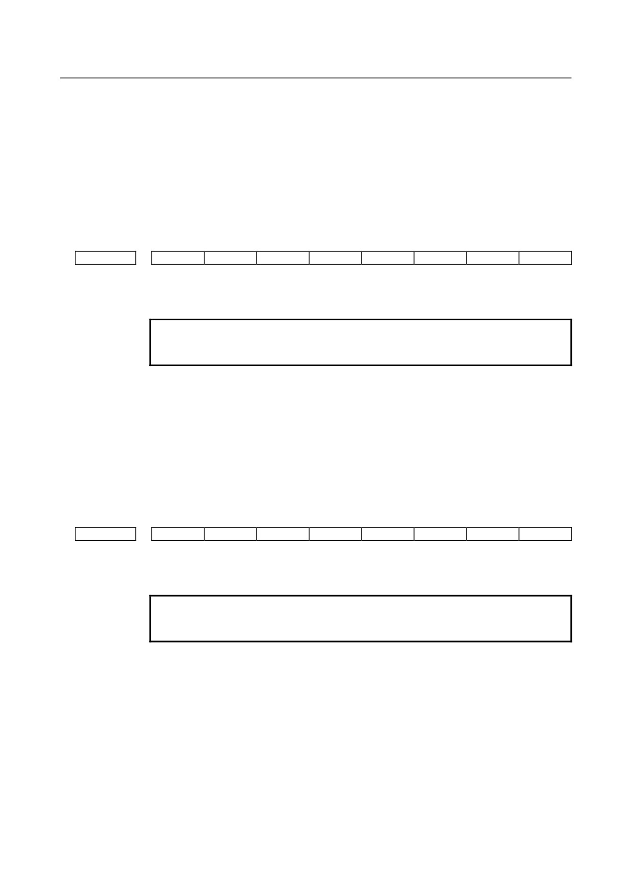
#0 AAC
0: Does not perform angular axis control.
1: Performs inclined axis control.
#2 AZR
0: The machine tool is moved along the Cartesian axis during manual reference
position return along the slanted axis under angular axis control.
1: The machine tool is not moved along the Cartesian axis during manual reference
position return along the slanted axis under angular axis control.
#7
#6
#5
#4
#3
#2
#1
#0
8201
ADG
AO3
AO2
AOT
[Input type] Parameter input
[Data type] Bit path
NOTE
When at least one of these parameters is set, the power must be
turned off before operation is continued.
#0 AOT Stored stroke limit 1 under angular axis control is handled as:
0: Value in the slanted coordinate system.
1: Value in the Cartesian coordinate system.
#1 AO2 Stored stroke limit 2 under angular axis control is handled as:
0: Value in the slanted coordinate system.
1: Value in the Cartesian coordinate system.
#2 AO3 Stored stroke limit 3 under angular axis control is handled as:
0: Value in the slanted coordinate system.
1: Value in the Cartesian coordinate system.
- 909 -
A.PARAMETERS
APPENDIX
B-64304EN/02
#7 ADG The contents of diagnostic data Nos. 306 and 307 are:
0: Not swapped. The slanted axis and Cartesian axis are displayed in this order.
1: Swapped. The Cartesian axis and slanted axis are displayed in this order.
8210
Slant angle of a slanted axis in angular axis control
[Input type] Parameter input
[Data type] Real path
[Unit of data] Degree
[Min. unit of data] Depend on the increment system of the applied axis
[Valid data range] -180.000 to 180.000. However, angular axis control is disabled in the ranges -95.000 to
-85.000 and 85.000 to 95.000 (in the case of IS-B).
8211
Axis number of a slanted axis subject to angular axis control
8212
Axis number of a Cartesian axis subject to slanted axis control
NOTE
When these parameters are set, the power must be turned off before
operation is continued.
[Input type] Parameter input
[Data type] Word path
[Valid data range] 1 to number of controlled axes
When angular axis control is to be applied to an arbitrary axis, these parameters set the
axis numbers of a slanted axis and Cartesian axis. If 0 is set in either of the two
parameters, the same number is set in the two parameters, or a number other than the
controlled axis numbers is set in either of the two parameters, a slanted axis and Cartesian
axis are selected as indicated in the following table:
Slanted axis
Cartesian axis
Y-axis (axis with 2 set in parameter No.
Z-axis (axis with 3 set in parameter No.
M series
1022) of the basic three axes
1022) of the basic three axes
X-axis (axis with 1 set in parameter No.
Z-axis (axis with 3 set in parameter No.
T series
1022) of the basic three axes
1022) of the basic three axes
#7
#6
#5
#4
#3
#2
#1
#0
8301
SYA
[Input type] Parameter input
[Data type] Bit path
#4 SYA In the servo-off state in axis synchronous control, the limit of the difference between the
positioning deviation of the master axis and that of the slave axis is:
0: Checked.
1: Not checked.
#7
#6
#5
#4
#3
#2
#1
#0
8302
SMA
[Input type] Parameter input
[Data type] Bit path
- 910 -
B-64304EN/02
APPENDIX
A.PARAMETERS
NOTE
When this parameter is set, the power must be turned off before
operation is continued.
#7 SMA When an absolute position detector is attached, and bit 4 (APZ) of parameter No. 1815
for an axis in synchronous operation is set to OFF, APZ of the pairing axis
in
synchronous operation is:
0: Not set to OFF.
1: Set to OFF.
#7
#6
#5
#4
#3
#2
#1
#0
8303
SOFx
SAFx
ATSx
ATEx
[Input type] Parameter input
[Data type] Bit axis
NOTE
When at least one of these parameters is set, the power must be
turned off before operation is continued.
#0 ATEx In axis synchronous control, automatic setting for grid positioning is:
0: Disabled
1: Enabled
Set this parameter with a slave axis.
#1 ATSx In axis synchronous control, automatic setting for grid positioning is:
0: Not started
1: Started
Set this parameter with a slave axis.
NOTE
When starting automatic setting for grid positioning, set ATS to 1.
Upon the completion of setting, ATS is automatically set to 0.
#2 SAFx In axis synchronous control, a movement along a slave axis is:
0: Not added to actual feedrate display.
1: Added to actual feedrate display.
Set this parameter with a slave axis.
#7 SOFx In axis synchronous control, the synchronization establishment function based
on
machine coordinates is:
0: Disabled.
1: Enabled.
Set this parameter with a slave axis.
0.
#7
#6
#5
#4
#3
#2
#1
#0
8304
SYEx
SCAx
MVBx
ADJx
SSAx
[Input type] Parameter input
[Data type] Bit axis
- 911 -

A.PARAMETERS
APPENDIX
B-64304EN/02
#0 SSAx When the one-direction synchronization establishment function under axis synchronous
control is used:
0: The axis with a larger machine coordinate is used as the reference.
1: The axis with a smaller machine coordinate is used as the reference.
NOTE
1 When at least one of these parameters is set, the power must be
turned off before operation is continued.
2 Set this parameter (SSA) to the same value for both the master
and slave axes.
#2 ADJx In axis synchronous control, this parameter specifies an axis along which a movement is
made in the modification mode.
0: A movement is not made in the modification mode along the axis.
1: A movement is made in the modification mode along the axis.
When this parameter is set to 1, the modification mode is set.
Along an axis with this parameter set to 1, a movement is made by a move command for
the master axis.
Set this parameter for one of the master and slave axes.
When there are multiple slave axes for one master axis, set this parameter to 1 for an axis
with which a synchronization error excessive alarm is issued for recovery. If an alarm is
issued with multiple axes, modify this parameter after recovery of one axis to recover
another axis.
#4 MVBx In the modification mode, a move command in a direction that increases a
synchronization error is:
0: Ignored.
1: Valid.
When there are multiple slave axes for one master axis, an attempt to reduce the
synchronous error of a slave axis by a movement along the master axis can increase the
synchronization error of another slave axis. If this parameter is set to 0 in such a case, a
movement can be made in neither direction along the master axis. In this case, set bit 2
(ADJ) of parameter No. 8304 to make a movement along a slave axis to perform a
corrective operation.
#5 SCAx In axis synchronous control:
0: Synchronous operation is performed when the axis synchronous control manual feed
selection signal SYNCJ or the axis synchronous control selection signal SYNC for
slave axes is set to 1.
1: Synchronous operation is performed at all times.
Set this parameter with a slave axis.
#7 SYEx When external machine coordinate system shift is specified by external data input/output
for the master axis in synchronous control, the slave axis is:
0: Not shifted.
1: Shifted by the same amount as specified for the master axis.
Set this parameter for the slave axis.
This function is disabled during normal operation.
#7
#6
#5
#4
#3
#2
#1
#0
8305
SSE
SSO
[Input type] Parameter input
[Data type] Bit path
- 912 -
B-64304EN/02
APPENDIX
A.PARAMETERS
#0 SSO The uni-directional synchronization function in axis synchronous control is:
0: Disabled.
1: Enabled.
#1 SSE After emergency stop, the uni-directional synchronization function in axis synchronous
control is:
0: Enabled.
1: Disabled.
8311
Axis number of master axis in axis synchronous control
NOTE
When this parameter is set, the power must be turned off before
operation is continued.
[Input type] Parameter input
[Data type] Byte axis
[Valid data range] 0 to Number of controlled axes
Select a master axis in axis synchronous control. In the parameter for the slave axis, set
the axis number of the master axis.
Example 1)
When one set of axis synchronous control is used:
When the master axis is the first axis (X-axis), and the slave axis is the third axis
(Z-axis), set parameter No. 8311 as follows:
Parameter No.8311 X (first axis) = 0
Parameter No.8311 Y (second axis) = 0
Parameter No.8311 Z (third axis) = 1
Parameter No.8311 A (fourth axis) = 0
Example 2)
When two sets of axis synchronous control is used:
When the master axes are the first axis and second axis, and the slave axes are the
fourth axis and third axis, set parameter No. 8311 as follows:
Parameter No.8311 X (first axis) = 0
Parameter No.8311 Y (second axis) = 0
Parameter No.8311 Z (third axis) = 2
Parameter No.8311 A (fourth axis) = 1
8312
Enabling/disabling mirror image in axis synchronous control
[Input type] Parameter input
[Data type] Word axis
[Valid data range] -127 to 128
This parameter sets mirror image for the slave axis. When 100 or a more value is set with
this parameter, the mirror image function is applied to synchronous control. Set this
parameter to the slave axis.
Example)
For reverse synchronization with the master axis being the third axis and the slave
axis being the fourth axis, set parameter No. 8312 as follows:
Parameter No.8312 X (first axis) = 0
Parameter No.8312 Y (second axis) = 0
Parameter No.8312 Z (third axis) = 0
Parameter No.8312 A (fourth axis) = 100
- 913 -
A.PARAMETERS
APPENDIX
B-64304EN/02
NOTE
In synchronous operation with mirror image applied,
synchronization establishment, synchronization error checking, and
modification mode cannot be used.
8314
Maximum allowable error in synchronization error check based on machine coordinates
[Input type] Parameter input
[Data type] Real axis
[Unit of data] mm, inch, degree (machine unit)
[Min. unit of data] Depend on the increment system of the applied axis
[Valid data range] 0 or positive 9 digit of minimum unit of data (refer to the standard parameter setting table
(B))
(When the increment system is IS-B, 0.0 to +999999.999)
This parameter sets a maximum allowable error in a synchronization error check based on
machine coordinates. When the error between the master and slave axes in machine
coordinates exceeds the value set in this parameter, the machine stops with the servo
alarm (SV0005).
Set this parameter with a slave axis.
NOTE
Set 0 in this parameter when a synchronization error check is not
made.
8323
Limit in positional deviation check in axis synchronous control
[Input type] Parameter input
[Data type] 2-word axis
[Unit of data] Detection unit
[Valid data range] 0 to 999999999
This parameter sets the maximum allowable difference between the master axis and slave
axis position deviations. When the absolute value of a positional deviation difference
exceeds the value set in this parameter in axis synchronous control, the alarm (DS0001) is
issued.
Set this parameter with a slave axis. If 0 is specified in this parameter, no position
deviation difference check is made.
8325
Maximum compensation value in synchronization establishment based on machine coordinates
[Input type] Parameter input
[Data type] Real axis
[Unit of data] mm, inch, degree (machine unit)
[Min. unit of data] Depend on the increment system of the applied axis
[Valid data range] 0 or positive 9 digit of minimum unit of data (refer to the standard parameter setting table
(B))
(When the increment system is IS-B, 0.0 to +999999.999)
This parameter sets the maximum compensation value for synchronization. When a
compensation value exceeding the value set in this parameter is detected, the servo alarm
(SV0001) is issued, and the synchronization establishment is not performed.
Specify a slave axis for this parameter. To enable this parameter, set the parameter SOF
(bit
7 of parameter No.8303) to 1. When 0 is set in this parameter, synchronization
establishment is not performed.
- 914 -

B-64304EN/02
APPENDIX
A.PARAMETERS
8326
Difference between master axis and slave axis reference counters
[Input type] Parameter input
[Data type] 2-word axis
[Unit of data] Detection unit
[Valid data range] 0 to 999999999
The difference between the master axis reference counter and slave axis reference counter
(master axis and slave axis grid shift) is automatically set when automatic setting for grid
positioning is performed. Then, the difference is transferred together with an ordinary
grid shift value to the servo system when the power is turned on. This parameter is set
with a slave axis.
8327
Torque difference alarm detection timer
[Input type] Parameter input
[Data type] 2-word axis
[Unit of data] msec
[Valid data range] 0 to 4000
This parameter sets a time from the servo preparation completion signal, SA <F000.6>,
being set to 1 until torque difference alarm detection is started in axis synchronous
control.
When 0 is set in this parameter, the specification of 512 msec is assumed.
Set this parameter with a slave axis.
8337
M code for turning off synchronization in axis synchronous control
[Input type] Parameter input
[Data type] 2-word path
[Valid data range] 1 to 99999999
This parameter specifies an M code for switching from synchronous operation to normal
operation.
The M code set in this parameter is not buffered.
8338
M code for turning on synchronization in axis synchronous control
[Input type] Parameter input
[Data type] 2-word path
[Valid data range] 1 to 99999999
This parameter specifies an M code for switching from normal operation to synchronous
operation.
The M code set in this parameter is not buffered.
8465
Upper limit of the speed of advance preview control/AI advance preview control/AI contour control
[Input type] Setting input
[Data type] Real path
[Unit of data] mm/min, inch/min, degree/min (input unit)
[Min. unit of data] Depend on the increment system of the reference axis
[Valid data range] Refer to the standard parameter setting table (C)
(When the increment system is IS-B, 0.0 to +999000.0)
This parameter sets the upper limit of the speed of advance preview control/AI advance
preview control/AI contour control.
If a speed higher than this parameter is specified in the advance preview control/AI
advance preview control/AI contour control mode, clamping is performed at the speed
specified by this parameter.
- 915 -
A.PARAMETERS
APPENDIX
B-64304EN/02
When this parameter is 0, clamping is not performed.
#7
#6
#5
#4
#3
#2
#1
#0
8900
PWE
[Input type] Setting input
[Data type] Bit
#0 PWE The setting, from an external device and MDI panel, of those parameters that cannot be
set by setting input is:
0: Disabled.
1: Enabled.
10461
RGB value of color palette 1 for text for color set 3
10462
RGB value of color palette 2 for text for color set 3
:
10475
RGB value of color palette 15 for text for color set 3
[Input type] Parameter input
[Data type] 2-word
[Valid data range] 0 to 151515
Each of these parameters sets the RGB value of each color palette for text by specifying a
6-digit number as described below.
rrggbb: 6-digit number (rr: red data, gg: green data, bb: blue data)
The valid data range of each color is 0 to 15 (same as the tone levels on the color setting
screen). When a number equal to or greater than 16 is specified, the specification of 15 is
assumed.
Example)
When the tone level of a color is: red:1 green:2, blue:3, set 10203 in the parameter.
#7
#6
#5
#4
#3
#2
#1
#0
SIC
11005
[Input type] Parameter input
[Data type] Bit
#0 SIC Spindle indexing is:
0: Performed based on absolute coordinates.
1: Performed based on machine coordinates.
Path number with which the rotation of each spindle is specified
11090
[Input type] Parameter input
[Data type] Byte spindle
[Valid data range] 0 to 2
When a path is specified for spindle commands, this parameter sets a path number with
which the rotation of a spindle can be specified.
0: Spindle commands can be issued from both paths.
1 to 2: Spindle commands can be issued from a set path.
- 916 -
B-64304EN/02
APPENDIX
A.PARAMETERS
NOTE
1 This parameter is valid when SPSP<Gn536.7> is set to 1.
2 If the setting is illegal, an alarm (PS5305) is issued when a spindle
command is issued from any one of the paths.
3 This setting does not apply to spindle commands using the spindle
select signals (SWS1 and SWS2<Gn027.0 and 1>).
#7
#6
#5
#4
#3
#2
#1
#0
11222
CIM
NIM
[Input type] Parameter input
[Data type] Bit path
#0 NIM Automatic conversion of a coordinate system by an inch/metric conversion command
(G20 or G21) is:
0: Not performed.
1: Performed.
#1 CIM When an inch/metric conversion command (G20 or G21) is specified, if the workpiece
coordinate system is shifted by the shift amount as described below:
0: An alarm (PS1298) is issued.
1: Clearing is performed.
This parameter is valid when bit 0 (NIM) of parameter No. 11222 is 1 or bit 2 (IRF) of
parameter No. 14000 is 1 and clears the following items.:
• Manual intervention made when the manual absolute signal is off
• Issuance of a move command with the machine locked
• Movement by handle interrupt
• Operation with a mirror image
• Shifting of a workpiece coordinate system when a local coordinate system or
workpiece coordinate system is set up
11307
Display sequence of the coordinates in current position display
NOTE
When this parameter is set, the power must be turned off before
operation is continued.
[Input type] Parameter input
[Data type] Byte path
[Valid data range] 0 to 5
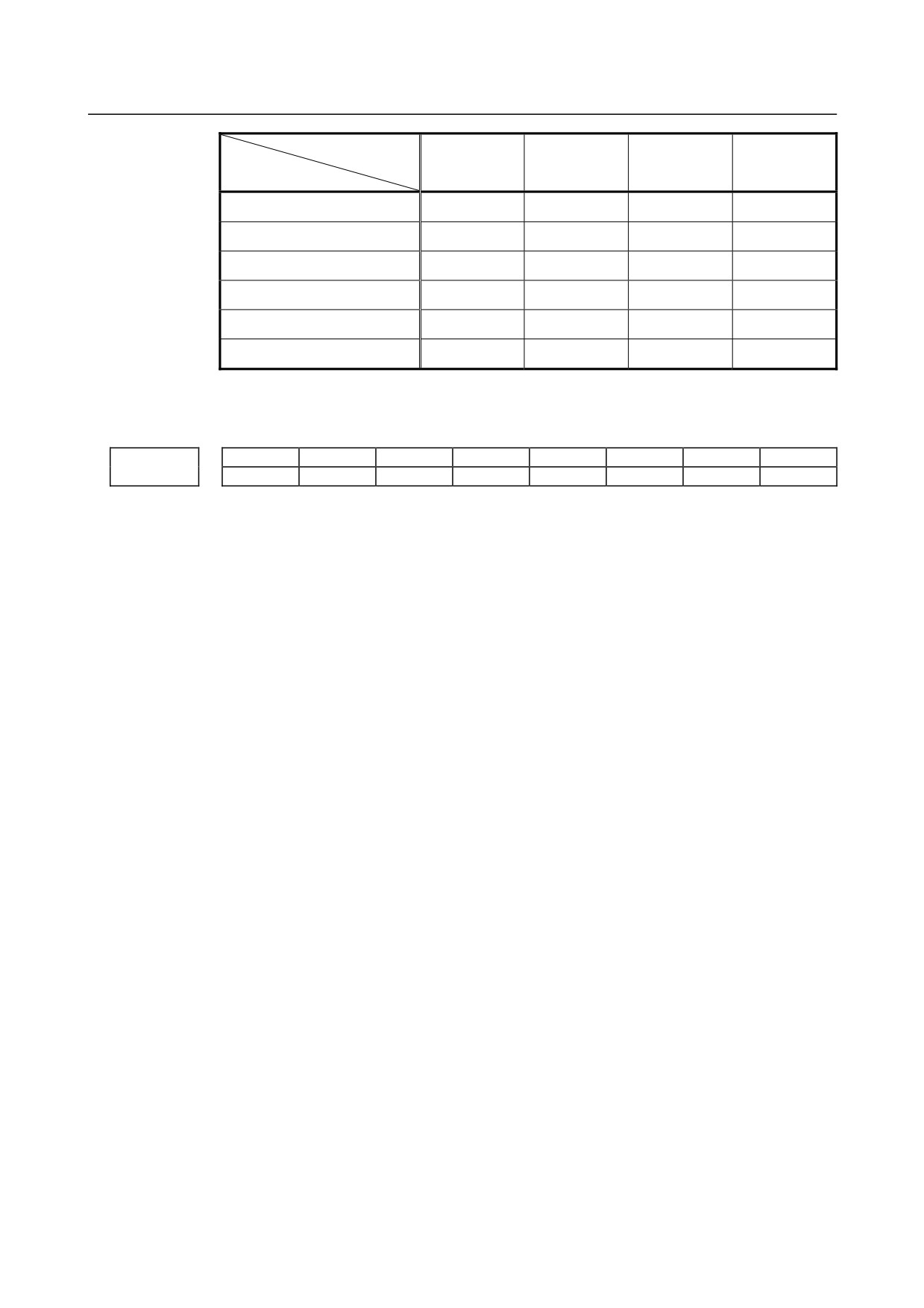
This parameter sets the display sequence of the coordinates of a position displayed on the
following screens:
10.4- inch display units
• Total position display screen
• Total position display on each screen
8.4-inch display units
• Total position display screen
The display sequence of coordinates corresponds to the parameter setting as follows:
- 917 -
A.PARAMETERS
APPENDIX
B-64304EN/02
Display sequence of
coordinates
1
2
3
4
Setting
Relative
Absolute
Machine
Remaining
0
coordinates
coordinates
coordinates
travel distance
Relative
Machine
Absolute
Remaining
1
coordinates
coordinates
coordinates
travel distance
Relative
Remaining
Absolute
Machine
2
coordinates
travel distance
coordinates
coordinates
Absolute
Machine
Relative
Remaining
3
coordinates
coordinates
coordinates
travel distance
Absolute
Remaining
Relative
Machine
4
coordinates
travel distance
coordinates
coordinates
Machine
Remaining
Relative
Absolute
5
coordinates
travel distance
coordinates
coordinates
If the setting is beyond the valid data range, 0 is assumed.
#7
#6
#5
#4
#3
#2
#1
#0
11329
GST
ACT
AER
GTF
BGM
GTL
DPC
[Input type] Parameter input
[Data type] Bit path
#1 DPC The current coordinates displayed on each screen of the dynamic graphic display function
are:
0: Absolute coordinates.
1: Machine coordinates.
#2 GTL When animated simulation is performed with the dynamic graphic display function,
drawing at positions with tool length compensation considered is:
0: Not performed.
1: Performed.
#3 BGM Coordinates used by the dynamic graphic display function are:
0: Absolute coordinates.
1: Machine coordinates.
#4 GTF In tool path drawing with the dynamic graphic display function, drawing at in a position
where tool compensation (tool length compensation, cutter compensation) is considered
is:
0: Performed.
1: Not performed.
#5 AER When the tool path is drawn with the dynamic graphic display function, automatic erasure
at the start of drawing is:
0: Not performed.
1: Performed.
#6 ACT In tool path drawing with the dynamic graphic display function, the drawing color of a
tool path is:
0: Not changed automatically.
1: Changed automatically.
- 918 -
B-64304EN/02
APPENDIX
A.PARAMETERS
#7 GST When drawing cannot be performed for a command with the dynamic graphic display
function:
0: The command is ignored, and drawing continues without stopping drawing.
1: Drawing stops.
11330
Magnification of drawing in dynamic graphic display
[Input type] Parameter input
[Data type] Word path
[Unit of data] 0.01
[Valid data range] 1 to 10000
This parameter sets the magnification of the drawing range in the dynamic graphic
display function.
11331
Screen center coordinate value in the drawing range in dynamic graphic display
[Input type] Parameter input
[Data type] Real axis
[Unit of data] mm, inch (input unit)
[Min. unit of data] Depend on the increment system of the applied axis
[Valid data range] 9 digit of minimum unit of data (refer to standard parameter setting table (A))
(When the increment system is IS-B, -999999.999 to +999999.999㧕
This parameter sets the coordinate value of the center of the drawing range in the
dynamic graphic display function.
NOTE
If bit 3 (BGM) of parameter No. 11329 is set to 1, set the coordinate
value on each axis in the machine coordinate system.
11332
Drawing range of tool path drawing in dynamic graphic display (maximum value)
[Input type] Parameter input
[Data type] Real axis
[Unit of data] mm, inch (input unit)
[Min. unit of data] Depend on the increment system of the applied axis
[Valid data range] 9 digit of minimum unit of data (refer to standard parameter setting table (A))
(When the increment system is IS-B, -999999.999 to +999999.999)
This parameter sets the maximum coordinates in the drawing range in tool path drawing
with dynamic graphic display function.
11333
Drawing range of tool path drawing in dynamic graphic display (minimum value)
[Input type] Parameter input
[Data type] Real axis
[Unit of data] mm, inch (input unit)
[Min. unit of data] Depend on the increment system of the applied axis
[Valid data range] 9 digit of minimum unit of data (refer to standard parameter setting table (A))
(When the increment system is IS-B, -999999.999 to +999999.999)
This parameter sets the minimum coordinates in the drawing range in tool path drawing
with dynamic graphic display function.
- 919 -
A.PARAMETERS
APPENDIX
B-64304EN/02
11334
Rotation angle of the drawing coordinate system in dynamic graphic display (vertical direction)
[Input type] Parameter input
[Data type] Word path
[Unit of data] degree
[Valid data range] -360 to 360
This parameter sets the rotation angle (vertical direction) of the drawing coordinate
system in the dynamic graphic display function.
11335
Rotation angle of the drawing coordinate system in dynamic graphic display (horizontal direction)
[Input type] Parameter input
[Data type] Word path
[Unit of data] degree
[Valid data range] -360 to 360
This parameter sets the rotation angle of the drawing coordinate system in the dynamic
graphic display function (the angle of rotation about the vertical axis on the screen, that
passes the center position of the blank).
11336
Drawing color of the tool path in tool path drawing in dynamic graphic display
[Input type] Parameter input
[Data type] Byte path
[Valid data range] 0 to 6
This parameter sets the color in which the tool path is drawn with the dynamic graphic
display function.
11337
Color of the cursor indicating the tool position on the PATH GRAPHIC (TOOL POSITION) screen of
dynamic graphic display
[Input type] Parameter input
[Data type] Byte path
[Valid data range] 0 to 6
This parameter sets the color of the cursor indicating the tool position on the PATH
GRAPHIC (TOOL POSITION) screen of the dynamic graphic display function.
11339
Drawing start sequence number in dynamic graphic display
[Input type] Parameter input
[Data type] 2-word path
[Valid data range] 0 to 99999999
This parameter sets the sequence number at which drawing is started by the dynamic
graphic display function.
11340
Drawing end sequence number in dynamic graphic display
[Input type] Parameter input
[Data type] 2-word path
- 920 -
B-64304EN/02
APPENDIX
A.PARAMETERS
[Valid data range] 0 to 99999999
This parameter sets the sequence number at which drawing is ended by the dynamic
graphic display function.
11341
Drawing color of a blank figure in dynamic graphic display
[Input type] Parameter input
[Data type] Byte path
[Valid data range] 0 to 6
This parameter sets the color in which a blank figure is drawn with the dynamic graphic
display function.
11342
Rotation angle of the drawing coordinate system of dynamic graphic display (screen center)
[Input type] Parameter input
[Data type] Word path
[Unit of data] degree
[Valid data range] -360 to 360
This parameter sets the rotation angle of the drawing coordinate system in dynamic
graphic display function (the angle of rotation about the vertical axis on the screen plane,
that passes the center position of the blank).
11343
Blank figure in dynamic graphic display
[Input type] Parameter input
[Data type] Byte path
[Valid data range] 0 to 1
This parameter sets the type of a blank figure in dynamic graphic display function.
Setting
Figure
0
Cylinder or hollow cylinder (parallel to the Z-axis)
1
Rectangular parallelepiped
11344
Blank reference position in dynamic graphic display
[Input type] Parameter input
[Data type] Real axis
[Unit of data] mm, inch (input unit)
[Min. unit of data] Depend on the increment system of the applied axis
[Valid data range] 9 digit of minimum unit of data (refer to standard parameter setting table (A))
(When the increment system is IS-B, -999999.999 to +999999.999㧕
This parameter sets the reference position of a blank in the dynamic graphic display
function by using coordinate values in the workpiece coordinate system.
- 921 -
A.PARAMETERS
APPENDIX
B-64304EN/02
11345
Blank dimension I in dynamic graphic display
11346
Blank dimension J in dynamic graphic display
11347
Blank dimension K in dynamic graphic display
[Input type] Parameter input
[Data type] Real axis
[Unit of data] mm, inch (input unit)
[Min. unit of data] Depend on the increment system of the reference axis
[Valid data range] 0 or positive 9 digit of minimum unit of data (refer to the standard parameter setting table
(B))
(When the increment system is IS-B, 0.000 to +999999.999)
These parameters set the dimensions of a blank in the dynamic graphic display function
according to the blank figure as follows:
Blank figure
Address I
Address J
Address K
Rectangular
Length in the X-axis
Length in the Y-axis
Length in the Z-axis
parallelepiped
direction
direction
direction
Cylinder
Radius of a cylinder
0
Length of a cylinder
Barrel
Radius of the outer
Radius of the inner
Length of a barrel
circle of a barrel
circle of a barrel
11348
Drawing color of a tool in animated simulation in dynamic graphic display
[Input type] Parameter input
[Data type] Byte path
[Valid data range] 0 to 6
This parameter sets the color in which a tool is drawn during animated simulation in the
dynamic graphic display function.
#7
#6
#5
#4
#3
#2
#1
#0
11349
GSP
ABC
[Input type] Parameter input
[Data type] Bit
#1 ABC In animated simulation in the dynamic graphic display function, when a fine boring cycle
or back boring cycle, which is a hole machining canned cycle, is performed, the
movement for a shift at the hole bottom is:
0: Not drawn.
1: Drawn.
#2 GSP In tool path drawing in the dynamic graphic display function, the drawing start position
is:
0: The end position of a block that makes a movement for the first time.
1: The current position.
- 922 -
B-64304EN/02
APPENDIX
A.PARAMETERS
NOTE
When G92, G52, or G92.1 is specified at the beginning of a
program to be drawn, the position specified in this G code is
assumed to be the drawing start position.
#7
#6
#5
#4
#3
#2
#1
#0
11350
PNE
[Input type] Parameter input
[Data type] Bit
#2 PNE A magnified path name is:
0: Not displayed.
1: Displayed.
NOTE
When this parameter is set, the power must be turned off before
operation is continued.
The parameter is valid only for the 10.4-inch display.
#7
#6
#5
#4
#3
#2
#1
#0
11352
PNI
[Input type] Parameter input
[Data type] Bit
#0 PNI A magnified path name is displayed in:
0: Normal video.
1: Reverse video.
NOTE
The parameter is valid only for the 10.4-inch display.
#7
#6
#5
#4
#3
#2
#1
#0
11353
SEK
[Input type] Parameter input
[Data type] Bit
#0 SEK When the power is turned on, or when the clear state is present, sequence numbers are:
0: Not maintained.
1: Maintained.
NOTE
During a subprogram call, the sequence number of the subprogram
is maintained.
11363
Radius of a tool figure in dynamic graphic display
[Input type] Parameter input
[Data type] Real axis
[Unit of data] mm, inch (input unit)
- 923 -
A.PARAMETERS
APPENDIX
B-64304EN/02
[Min. unit of data] Depend on the increment system of the reference axis
[Valid data range] 0 or positive 9 digit of minimum unit of data (refer to the standard parameter setting table
(B))
(When the increment system is IS-B, 0.000 to +999999.999)
This parameter sets the radius of a tool figure in animated simulation with the dynamic
graphic display function.
#7
#6
#5
#4
#3
#2
#1
#0
11630
FRD
[Input type] Parameter input
[Data type] Bit path
#0 FRD The minimum command unit of the rotation angles of coordinate rotation is:
0:
0.001 degree.
1:
0.00001 degree. (1/100,000)
Identification Number for synchronous, composite and superimposed control with program command
12600
[Input type] Parameter input
[Data type] Word axis
[Valid data range] 0,1 to 32767
Set identification numbers that can be specified with P,Q addresses.
The axis whose identification number is "0" cannot become under synchronous
/composite /superimposed control by CNC program.
The same identification number cannot be set to two or more axes through all paths.
When the same identification number is set, PS alarm
(PS5339) occurs
at
G50.4/G50.5/G50.6/G51.4/G51.5/G51.6 block.
12990
(1st) G code modal group to be recorded in the history when an alarm is issued
12991
(2nd) G code modal group to be recorded in the history when an alarm is issued
12992
(3rd) G code modal group to be recorded in the history when an alarm is issued
12993
(4th) G code modal group to be recorded in the history when an alarm is issued
12994
(5th) G code modal group to be recorded in the history when an alarm is issued
12995
(6th) G code modal group to be recorded in the history when an alarm is issued
12996
(7th) G code modal group to be recorded in the history when an alarm is issued
12997
(8th) G code modal group to be recorded in the history when an alarm is issued
12998
(9th) G code modal group to be recorded in the history when an alarm is issued
12999
(10th) G code modal group to be recorded in the history when an alarm is issued
[Input type] Parameter input
[Data type] Byte path
[Valid data range] 1 to the maximum number of G code groups
- 924 -
B-64304EN/02
APPENDIX
A.PARAMETERS
Set the number of a G code modal group to be recorded in the alarm history and operation
history when an alarm is issued.
* If a value beyond the valid data range is set, the status of group 04 is recorded.
13221
M code for tool life count restart
[Input type] Parameter input
[Data type] Word path
[Valid data range] 0 to 255 (not including 01, 02, 30, 98, and 99)
When 0 is set, this parameter is ignored.
For the operation of an M code for tool life count restart, see the description of parameter
No. 6811.
This parameter is used when an M code for tool life count restart exceeds 127.
Set parameter No. 6811 to 0, and set the value of an M code in this parameter.
13265
H code for using the tool length offset in tool life management
[Input type] Parameter input
[Data type] 2-word path
[Valid data range] 0 to 9999
Setting this parameter to H99 generally validates the compensation for the tool currently
being used. By setting any H code in this parameter, the H code instead of H99 can be
used. If 0 is specified, H99 is assumed.
A value ranging from 0 to 9999 can be set.
13266
D code for enabling cutter compensation in tool life management
[Input type] Parameter input
[Data type] 2-word path
[Valid data range] 0 to 9999
Setting this parameter to D99 generally validates the compensation for the tool currently
being used. By setting any D code in this parameter, the D code instead of D99 can be
used. If 0 is set, D99 is assumed.
#7
#6
#5
#4
#3
#2
#1
#0
MCR
13600
MSA
MCR
[Input type] Parameter input
[Data type] Bit path
#0 MCR When an allowable acceleration rate adjustment is made with the machining condition
selection function
(machining parameter adjustment screen, precision level selection
screen), parameter No.
1735 for the deceleration function based on acceleration in
circular interpolation is:
0: Modified.
1: Not modified.
#7 MSA When the machining condition selection function is used, the acceleration rate change
time (bell-shaped) (LV1, LV10) is:
0: Set using parameter Nos. 13612 and 13613.
1: Set using parameter Nos. 13662 and 13663.
- 925 -
A.PARAMETERS
APPENDIX
B-64304EN/02
#7
#6
#5
#4
#3
#2
#1
#0
13601
MPR
NOTE
When this parameter is set, the power must be turned off before
operation is continued.
[Input type] Parameter input
[Data type] Bit
#0 MPR The machining parameter adjustment screen is:
0: Displayed.
1: Not displayed.
Even when this parameter is set to 1, the precision level selection screen is displayed.
Acceleration rate for acceleration/deceleration before look-ahead interpolation in advanced preview
13610
control/AI advanced preview control/AI contour control (precision level 1)
Acceleration rate for acceleration/deceleration before look-ahead interpolation in advanced preview
13611
control/AI advanced preview control/AI contour control (precision level 10)
[Input type] Parameter input
[Data type] Real axis
[Unit of data] mm/sec/sec, inch/sec/sec, degree/sec/sec (machine unit)
[Min. unit of data] Depend on the increment system of the applied axis
[Valid data range] Refer to the standard parameter setting table (D)
(When the machine system is metric system, 0.0 to +100000.0. When the machine system
is inch system, machine, 0.0 to +10000.0)
Each of these parameters sets an acceleration rate for acceleration/ deceleration before
interpolation in advanced preview control/AI advanced preview control/AI contour
control. Set a value (precision level 1) with emphasis placed on speed, and a value
(precision level 10) with emphasis on precision.
13612
Acceleration rate change time (bell-shaped) when AI contour control is used (precision level 1)
13613
Acceleration rate change time (bell-shaped) when AI contour control is used (precision level 10)
[Input type] Parameter input
[Data type] Byte path
[Unit of data] msec
[Valid data range] 0 to 127
Each of these parameters sets an acceleration rate change time (bell-shaped) in AI contour
control. Set a value (precision level 1) with emphasis placed on speed, and a value
(precision level 10) with emphasis on precision.
Allowable acceleration rate when advanced preview control/AI advanced preview control/AI contour
13620
control is used (precision level 1)
Allowable acceleration rate when advanced preview control/AI advanced preview control/AI contour
13621
control is used (precision level 10)
[Input type] Parameter input
[Data type] Real axis
- 926 -
B-64304EN/02
APPENDIX
A.PARAMETERS
[Unit of data] mm/sec/sec, inch/sec/sec, degree/sec/sec (machine unit)
[Min. unit of data] Depend on the increment system of the applied axis
[Valid data range] Refer to the standard parameter setting table (D)
(When the machine system is metric system, 0.0 to +100000.0. When the machine system
is inch system, machine, 0.0 to +10000.0)
Each of these parameters sets an allowable acceleration rate in advanced preview
control/AI advanced preview control/AI contour control. Set a value (precision level 1)
with emphasis placed on speed, and a value (precision level 10) with emphasis on
precision.
Time constant for acceleration/deceleration after interpolation when advanced preview control/AI
13622
advanced preview control/AI contour control is used (precision level 1)
Time constant for acceleration/deceleration after interpolation when advanced preview control/AI
13623
advanced preview control/AI contour control is used (precision level 10)
[Input type] Parameter input
[Data type] Word axis
[Unit of data] msec
[Valid data range] 1 to 512
Each of these parameters sets a time constant for acceleration/ deceleration after
interpolation when advanced preview control/AI advanced preview control/AI contour
control is used. Set a value (precision level 1) with emphasis placed on speed, and a value
(precision level 10) with emphasis on precision.
Corner speed difference when advanced preview control/AI advanced preview control/AI contour
13624
control is used (precision level 1)
Corner speed difference when advanced preview control/AI advanced preview control/AI contour
13625
control is used (precision level 10)
[Input type] Parameter input
[Data type] Real axis
[Unit of data] mm/min, inch/min, degree/min (machine unit)
[Min. unit of data] Depend on the increment system of the applied axis
[Valid data range] Refer to the standard parameter setting table (C)
(When the increment system is IS-B, 0.0 to +999000.0)
Each of these parameters sets an allowable speed difference for speed determination
based on corner speed difference in advanced preview control/AI advanced preview
control/AI contour control. Set a value (precision level 1) with emphasis placed on speed,
and a value (precision level 10) with emphasis on precision.
Maximum cutting speed when advanced preview control/AI advanced preview control/AI contour
13626
control is used (precision level 1)
Maximum cutting speed when advanced preview control/AI advanced preview control/AI contour
13627
control is used (precision level 10)
[Input type] Parameter input
[Data type] Real axis
[Unit of data] mm/min, inch/min, degree/min (machine unit)
[Min. unit of data] Depend on the increment system of the applied axis
[Valid data range] Refer to the standard parameter setting table (C)
(When the increment system is IS-B, 0.0 to +999000.0)
- 927 -
A.PARAMETERS
APPENDIX
B-64304EN/02
Each of these parameters sets a maximum cutting speed in advanced preview control/AI
advanced preview control/AI contour control. Set a value
(precision level
1) with
emphasis placed on speed, and a value (precision level 10) with emphasis on precision.
Parameter number corresponding to arbitrary item 1 when advanced preview control/AI advanced
13628
preview control/AI contour control is used
Parameter number corresponding to arbitrary item 2 when advanced preview control/AI advanced
13629
preview control/AI contour control is used
NOTE
When these parameters are set, the power must be turned off before
operation is continued.
[Input type] Parameter input
[Data type] 2-word path
[Valid data range] 1 to 65535
These parameters set the parameter numbers corresponding to arbitrary items 1 and 2.
NOTE
The parameter numbers corresponding to the following cannot be
specified:
• Bit parameters
• Spindle parameters (No. 4000 to No. 4799)
• Parameters of real number type
• Parameters that require power-off (for which the alarm
(PW0000) is issued)
• Nonexistent parameters
Value with emphasis on speed (precision level 1) of the parameter corresponding to arbitrary item 1
13630
when advanced preview control/AI advanced preview control/AI contour control is used
Value with emphasis on speed (precision level 1) of the parameter corresponding to arbitrary item 2
13631
when advanced preview control/AI advanced preview control/AI contour control is used
Value with emphasis on speed (precision level 10) of the parameter corresponding to arbitrary item 1
13632
when advanced preview control/AI advanced preview control/AI contour control is used
Value with emphasis on speed (precision level 10) of the parameter corresponding to arbitrary item 2
13633
when advanced preview control/AI advanced preview control/AI contour control is used
[Input type] Parameter input
[Data type] 2-word axis
[Unit of data] Depend on the type of parameter for an arbitrary item
[Valid data range] Depend on the type of parameter for an arbitrary item
Each of these parameters sets a value with emphasis placed on speed or precision for a
parameter.
- 928 -
B-64304EN/02
APPENDIX
A.PARAMETERS
13662
Acceleration rate change time (bell-shaped) when AI contour control is used (precision level 1), range
extended
13663
Acceleration rate change time (bell-shaped) when AI contour control is used (precision level 10), range
extended
[Input type] Parameter input
[Data type] 2-word path
[Unit of data] msec
[Valid data range] 0 to 200
Each of these parameters sets an acceleration rate change time (bell-shaped) in AI contour
control. Set a value (precision 1) with emphasis placed on speed, and a value (precision
level 10) with emphasis on precision.
#7
#6
#5
#4
#3
#2
#1
#0
14000
IRFx
NOTE
When this parameter is set, the power must be turned off before
operation is continued.
[Input type] Parameter input
[Data type] Bit axis
#2 IRFx An inch-metric switch command (G20, G21) at the reference position is:
0: Disabled.
1: Enabled.
When this function is enabled for an axis, if an attempt to switch between the inch and
metric unit is made although the tool is not at the reference position on that axis, an alarm
(PS5362) is issued, and switching between the inch and metric unit is canceled.
Be sure to move the tool to the reference position by, for example, specifying G28 before
switching between the inch and metric unit.
NOTE
1 This function enables the inch/metric switching commands (G20
and G21) at the reference position. It does not enable the
switching of the setting input unit (bit 2 (INI) of parameter No.
0000).
2 Switching between inch and metric by setting the setting input unit
(bit 2 (INI) of parameter No. 0000) is enabled only when the
machine coordinate of the first reference position is 0 (parameter
No. 1240 is 0) and presence on the first reference position is
assumed.
For a system in which the machine coordinate of the first reference
position is not 0, set this parameter to 1 and specify G20/G21 in the
first reference position to switch between inch and metric.
Maximum allowable travel distance when the reference position is established for a linear scale with an
14010
absolute address reference position
[Input type] Parameter input
- 929 -
A.PARAMETERS
APPENDIX
B-64304EN/02
[Data type] 2-word axis
[Unit of data] Detection unit
[Valid data range] 0 to 99999999
This parameter sets the maximum allowable travel distance at the FL feedrate when the
reference position is established for a linear scale with an absolute address reference
position. When the travel distance exceeds the setting of this parameter, the alarm
(DS0017)
(SCALE WITH REFERENCE POSITION: REFERENCE POSITION
ESTABLISHMENT FAILED) is issued. When this parameter is set to 0, the maximum
allowable travel distance is not checked.
14340
ATR value corresponding to slave 01 on FSSB
to
to
14357
ATR value corresponding to slave 18 on FSSB
NOTE
When these parameters are set, the power must be turned off before
operation is continued.
[Input type] Parameter input
[Data type] Byte
[Valid data range] 0 to 7,64,-56,-96
Each of these parameters sets the value (ATR value) of the address translation table
corresponding to each of slave 1 to slave 18 on FSSB.
The slave is a generic term for servo amplifiers and separate detector interface units
connected via an FSSB optical cable to the CNC. Numbers 1 to 18 are assigned to slaves,
with younger numbers sequentially assigned to slaves closer to the CNC.
A 2-axis amplifier consists of two slaves, and a 3-axis amplifier consists of three slaves.
In each of these parameters, set a value as described below, depending on whether the
slave is an amplifier, separate detector, or nonexistent.
• When the slave is an amplifier:
Set a value obtained by subtracting 1 from the setting of parameter No. 1023 for the
axis to which the amplifier is assigned.
• When the slave is a separate detector interface unit:
Set 64 for the first separate detector interface unit (connected near the CNC), and set
-56 for the second separate detector interface unit (connected far from the CNC).
• When the slave is nonexistent:
Set -96.
NOTE
1 When the electric gear box (EGB) function is used
Although an amplifier is not actually required for an EGB dummy
axis, set this parameter with assuming that a dummy amplifier is
connected. That is, as the address conversion table value for a
nonexistent slave, set the value obtained by subtracting 1 from the
setting of parameter No. 1023 for the EGB dummy axis, instead of
-96.
2 When the FSSB is set to the automatic setting mode (when the
parameter FMD (No.1902#0) is set to 0), parameter Nos. 14340 to
14357 are automatically set as data is input on the FSSB setting
screen. When the manual setting
2 mode is set
(when the
parameter FMD (No.1902#0) is set to 1), be sure to directly set
values in parameter Nos. 14340 to 14357.
- 930 -
B-64304EN/02
APPENDIX
A.PARAMETERS
Example of axis configuration and parameter settings
-
Example 1
CNC
Slave
ATR
number
No.14340
Controll
Program
Servo
Axis
to 14357
ed axis
axis name
axis
number
No.1020
No.1023
Single-axis
amplifier
1
0
X
1
X
1
2
1
A
2
Y
3
Two-axis
amplifier
3
Z
4
3
2
Y
4
A
2
Two-axis
4
3
Z
amplifier
5
B
5
5
4
B
M1
6
64
(M1)
M2
7
-56
(M2)
8 to 18
-96
(None)
CNC
Slave
ATR
number
No.14340
Controll
Program
Servo
Axis
to 14357
ed axis
axis name
axis
number
No.1020
No.1023
Single-axis
1
0
X
1
X
1
amplifier
2
2
Y
2
Y
3
Two-axis
amplifier
3
Z
4
3
3
Z
4
A
2
Two-axis
4
1
A
amplifier
5
B
5
5
4
B
M1
6
64
(M1)
M2
7
-56
(M2)
8 to 18
-96
(None)
M1/M2: First/second separate detector interface units
- 931 -
A.PARAMETERS
APPENDIX
B-64304EN/02
-
Example 2
Example of axis configuration and parameter settings when the electronic gear box (EGB) function is
used
(EGB slave axis: A-axis, EGB dummy axis: B-axis)
CNC
ATR
Slave
Controlled
Program
Servo
No.14340
Axis
number
axis
axis
axis
to 14357
number
name
No.1023
No.1020
Single-axis
1
0
X
1
X
1
amplifier
2
1
Y
2
Y
2
Two-axis
amplifier
3
Z
5
3
2
A
Single-axis
4
A
3
4
4
Z
amplifier
5
B
4
M1
5
64
(M1)
M2
6
-56
(M2)
7
3
B(Dummy)
8 to 18
-96
(None)
M1/M2: First/second separate detector interface units
14376
ATR value corresponding to connector 1 on the first separate detector interface unit
to
to
14383
ATR value corresponding to connector 8 on the first separate detector interface unit
14384
ATR value corresponding to connector 1 on the second separate detector interface unit
to
to
14391
ATR value corresponding to connector 8 on the third separate detector interface unit
NOTE
When these parameters are set, the power must be turned off before
operation is continued.
[Input type] Parameter input
[Data type] Byte
[Valid data range] 0 to 7, 32
Each of these parameters sets the value (ATR value) of the address translation table
corresponding to each connector on a separate detector interface unit.
In each of these parameters, set a value obtained by subtracting 1 from the setting of
parameter No. 1023 for the axis connected to a connector on a separate detector interface
unit.
When there are axes for which settings are made to use a separate detector interface unit
(bit 6 (PM1x) of parameter No. 1905 is set to 1 or bit 7 (PM2x) of parameter No. 1905 is
set to 1, set 32 for connectors not used.
- 932 -
B-64304EN/02
APPENDIX
A.PARAMETERS
NOTE
When the FSSB is set to the automatic setting mode (when the
parameter FMD (No.1902#0) is set to 0), parameter Nos. 14376 to
14391 are automatically set as data is input on the FSSB setting
screen. When the manual setting 2 mode is set (when the
parameter FMD (No.1902#0) is set to 1), be sure to directly set
values in parameter Nos. 14376 to 14391.
#7
#6
#5
#4
#3
#2
#1
#0
14476
DFS
[Input type] Parameter input
[Data type] Bit
#0 DFS The FSSB enters:
0: The FS0i-D-specific mode.
1: The FS0i-C-compatible mode.
14713
Unit of magnification by which enlargement and reduction is performed with the dynamic graphic
display function
[Input type] Parameter input
[Data type] Word
[Valid data range] 0 to 255
This parameter sets the unit of magnification by which enlargement and reduction is
performed with the dynamic graphic display function.
Unit of magnification = 64 / setting
If 0 is set, 64 is assumed.
14714
Unit of horizontal movement when a movement is made with the dynamic graphic display function
[Input type] Parameter input
[Data type] Word
[Valid data range] 0 to 255
This parameter sets the unit of horizontal movement (in dots) applied when a movement
is made with the dynamic graphic display function.
If 0 is set, 64 is assumed.
14715
Unit of vertical movement when a movement is made with the dynamic graphic display function
[Input type] Parameter input
[Data type] Word
[Valid data range] 0 to 255
This parameter sets the unit of vertical movement (in dots) applied when a movement is
made with the dynamic graphic display function.
If 0 is set, 35 is assumed.
14716
Unit of rotation angle when rotation is performed with the dynamic graphic display function
[Input type] Parameter input
- 933 -
A.PARAMETERS
APPENDIX
B-64304EN/02
[Data type] Word
[Valid data range] 0 to 255
This parameter sets the unit (in degrees) of a rotation angle by which the drawing
coordinate system is rotated with the dynamic graphic display function.
If 0 is set, 10 is assumed.
18060
Backward movement prohibition M code that outputs no M code
[Input type] Parameter input
[Data type] Word path
[Valid data range] 1 to 999
When an M code that prohibits backward movement is specified during backward
movement, backward movement of blocks before the M code is prohibited. In this case,
backward movement prohibition signal MRVSP<Fn091.2> is output.
This backward movement prohibition M code is not output to the PMC as an M code.
Set an M code that is not used by an auxiliary function or macro as the backward
movement prohibition M code.
18065
Backward movement prohibition M code 1 that outputs an M code
18066
Backward movement prohibition M code 2 that outputs an M code
[Input type] Parameter input
[Data type] Word path
[Valid data range] 1 to 999
When an M code that prohibits backward movement is specified during backward
movement, backward movement of blocks before the M code is prohibited. In this case,
backward movement prohibition signal MRVSP<Fn091.2> is output.
These backward movement prohibition M codes are output to the PMC as M codes. Set
M codes that are not used by an auxiliary function or macro as the backward movement
prohibition M codes.
#7
#6
#5
#4
#3
#2
#1
#0
19500
FNW
[Input type] Parameter input
[Data type] Bit path
#6 FNW In the speed determination method by the speed difference of advanced preview
control/AI advance preview control/AI contour control and the speed determination
method by the acceleration of advanced preview control/AI contour control:
0: The maximum speed that does not exceed the allowable speed difference or
allowable acceleration is selected.
1: The feedrate is determined so that the allowable speed difference and allowable
acceleration of each axis are not exceeded and that the deceleration speed is constant
regardless of the movement direction if the shape is the same.
#7
#6
#5
#4
#3
#2
#1
#0
19501
FRP
[Input type] Parameter input
[Data type] Bit path
- 934 -
B-64304EN/02
APPENDIX
A.PARAMETERS
#5 FRP linear-shaped rapid traverse in the advanced preview control/AI advance preview
control/AI contour control mode is:
0: Acceleration/deceleration after interpolation.
1: Acceleration/deceleration before interpolation.
Set a maximum allowable acceleration rate for each axis in parameter No. 1671.
When using bell-shaped acceleration/deceleration before interpolation, set an acceleration
rate change time in parameter No. 1672.
When this parameter is set to 1, acceleration/deceleration before interpolation is also
applied to rapid traverse if all conditions below are satisfied. At this time,
acceleration/deceleration after interpolation is not applied.
• Bit 1 (LRP) of parameter No. 1401 is set to 1: Linear interpolation type positioning
• A value other than 0 is set in parameter No. 1671 for an axis.
If all of these conditions are not satisfied, acceleration/deceleration after interpolation is
applied.
NOTE
To enable blinking display and signal output indicating the advance
preview control/AI advance preview control/AI contour control
mode even when rapid traverse command is specified, set bit 1
(AIR) of parameter No. 1612 to 1 in addition to the above settings.
#7
#6
#5
#4
#3
#2
#1
#0
19607
CAV
[Input type] Parameter input
[Data type] Bit path
#5 CAV When an interference check finds that interference (overcutting) occurred:
0: Machining stops with the alarm (PS0041).
(Interference check alarm function)
1: Machining is continued by changing the tool path to prevent interference
(overcutting) from occurring. (Interference check avoidance function)
For the interference check method, see the descriptions of bit 1 (CNC) of parameter No.
5008 and bit 3 (CNV) of parameter No. 5008.
- 935 -