FANUC Series 0i-MODEL D, Series 0i Mate-MODEL D. OPERATOR'S MANUAL - page 34
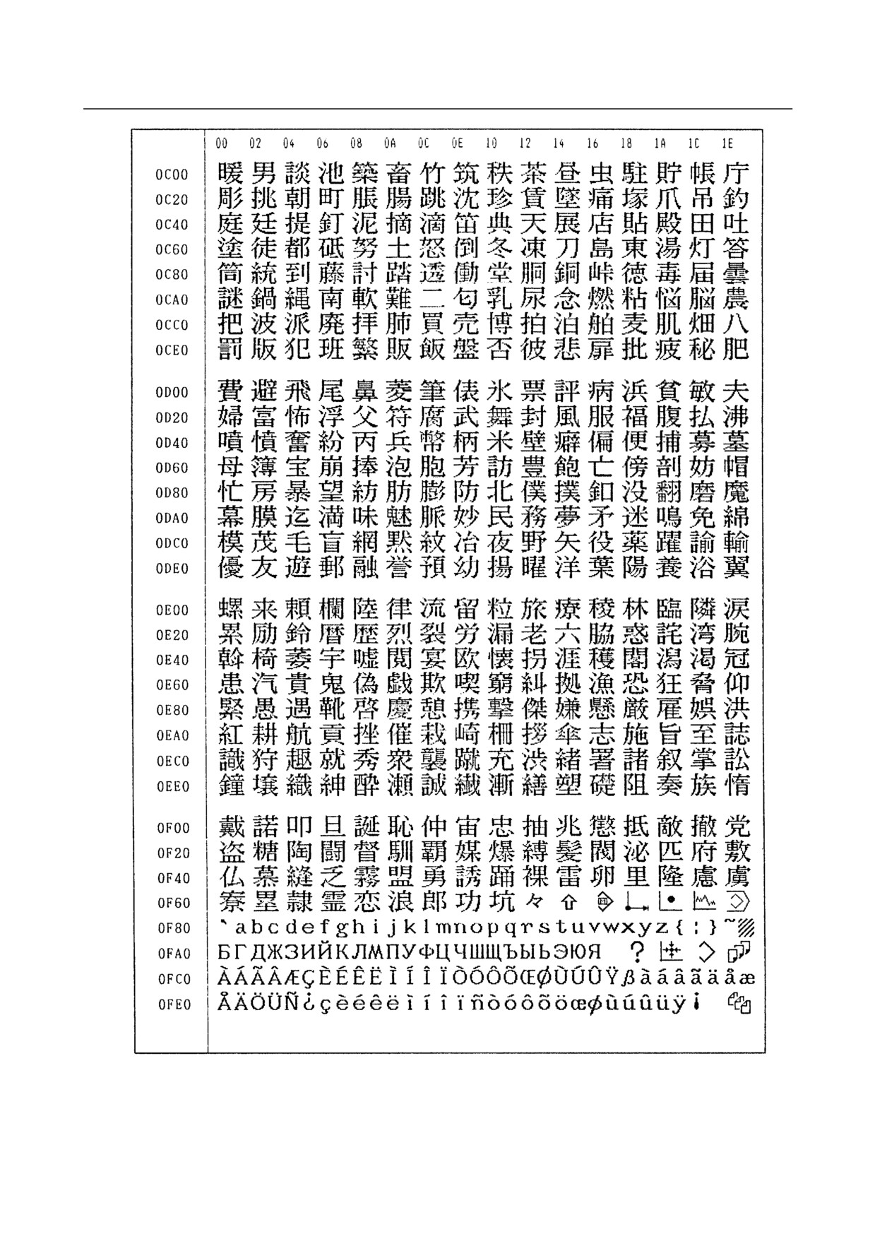
G. CHARACTER-TO-CODES
CORRESPONDENCE
APPENDIX
B-64304EN/02
- 966 -
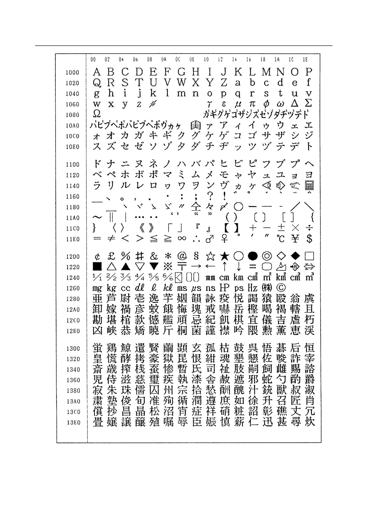
G.CHARACTER-TO-CODES
B-64304EN/02
APPENDIX
CORRESPONDENCE TABLE
- 967 -
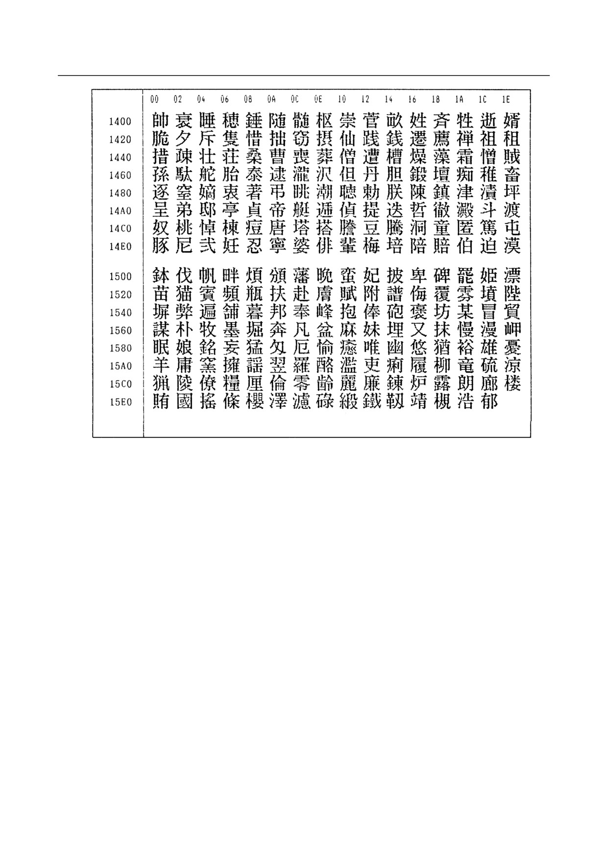
G. CHARACTER-TO-CODES
CORRESPONDENCE
APPENDIX
B-64304EN/02
- 968 -
B-64304EN/02
APPENDIX
H.ALARM LIST
H ALARM LIST
Appendix H, "ALARM LIST", consists of the following items:
(1) Alarms on program and operation (PS alarm)
969
(2) Background edit alarms (BG alarm)
969
(3) Communication alarms (SR alarm)
969
(4) Parameter writing alarm (SW alarm)
994
(5) Servo alarms (SV alarm)
994
(6) Overtravel alarms (OT alarm)
999
(7) Memory file alarms (IO alarm)
1000
(8) Alarms requiring power to be turned off (PW alarm)
1000
(9) Spindle alarms (SP alarm)
1001
(10) Alarm list (serial spindle)
1003
(11) Overheat alarms (OH alarm)
1011
(12) Other alarms (DS alarm)
1011
(13) Malfunction prevention function alarms (IE alarm)
1015
(1) Alarms on program and operation (PS alarm)
(2) Background edit alarms (BG alarm)
(3) Communication alarms (SR alarm)
Alarm numbers are common to all these alarm types.
Depending on the state, an alarm is displayed as in the following examples:
PS"alarm number"
Example: PS0003
BG"alarm number"
Example: BG0085
SR"alarm number"
Example: SR0001
Number
Message
Description
0001
TH ERROR
A TH error was detected during reading from an input device.
The read code that caused the TH error and how many
statements it is from the block can be verified in the
diagnostics screen.
0002
TV ERROR
An error was detected during the single-block TV error.
The TV check can be suppressed by setting TVC parameter
No. 0000#0 to “0”.
0003
TOO MANY DIGIT
Data entered with more digits than permitted in the NC
instruction word.
The number of permissible digits varies according to the
function and the word.
0004
ADDRESS NOT FOUND
NC word(s) address + numerical value not in word format.
This alarm is also generated when a custom macro does not
contain a reserved word, or does not conform to the syntax.
0005
NO DATA AFTER ADDRESS
NC word(s) address + numerical value not in word format.
This alarm is also generated when a custom macro does not
contain a reserved word, or does not conform to the syntax.
0006
ILLEGAL USE OF MINUS SIGN
A minus sign (-) was specified at an NC instruction word or
system variable where no minus signal may be specified.
0007
ILLEGAL USE OF DECIMAL POINT
A decimal point (.) was specified at an address where no
decimal point may be specified, or two decimal points were
specified.
0009
IMPROPER NC-ADDRESS
An illegal address was specified, or parameter 1020 is not set.
0010
IMPROPER G-CODE
An unusable G code is specified.
- 969 -
H.ALARM LIST
APPENDIX
B-64304EN/02
Number
Message
Description
0011
FEED ZERO ( COMMAND )
The cutting feedrate instructed by an F code has been set to
0.
This alarm is also generated if the F code instructed for the S
code is set extremely small in a rigid tapping instruction as the
tool cannot cut at the programmed lead.
0015
TOO MANY SIMULTANEOUS AXES
A move command was specified for more axes than can be
controlled by simultaneous axis control.
Either divide the number of programmed move axes into two
blocks.
0020
OVER TOLERANCE OF RADIUS
An arc was specified for which the difference in the radius at
the start and end points exceeds the value set in parameter
No. 3410. Check arc center codes I, J and K in the program.
The tool path when parameter No. 3410 is set to a large value
is spiral.
0021
ILLEGAL PLANE SELECT
The plane selection instructions G17 to G19 are in error.
Reprogram so that same 3 basic parallel axes are not
specified simultaneously.
This alarm is also generated when an axis that should not be
specified for plane machining is specified, for example, for
circular interpolation.
T
In the 0i -TD, the helical interpolation option is needed to
enable the specification of 3 or more axes for the G02/G03
block.
0022
R OR I,J,K COMMAND NOT FOUND
The command for circular interpolation lacks arc radius R or
coordinate I, J, or K of the distance between the start point to
the center of the arc.
0023
ILLEGAL RADIUS COMMAND
T
A negative value is specified for the arc radius R command. In
the T series, an arc at an angle larger than 180° cannot be
specified with the R command. Modify the program.
0025
CIRCLE CUT IN RAPID (F0)
M
F0 (rapid traverse in one-digit F code feed or inverse feed)
was specified during circular interpolation (G02, G03).
0027
NO AXES COMMANDED IN
M
G43/G44
No axis is specified in G43 and G44 blocks for the tool length
offset type C.
Offset is not canceled but another axis is offset for the tool
length offset type C.
Multiple axes were specified for the same block when the tool
length compensation type is C.
0028
ILLEGAL PLANE SELECT
The plane selection instructions G17 to G19 are in error.
Reprogram so that same 3 basic parallel axes are not
specified simultaneously.
This alarm is also generated when an axis that should not be
specified for plane machining is specified, for example, for
circular interpolation.
T
In the 0i -TD, the helical interpolation option is needed to
enable the specification of 3 or more axes for the G02/G03
block.
0029
ILLEGAL OFFSET VALUE
Illegal offset No.
0030
ILLEGAL OFFSET NUMBER
An illegal offset No. was specified.
- 970 -
B-64304EN/02
APPENDIX
H.ALARM LIST
Number
Message
Description
0031
ILLEGAL P COMMAND IN G10
Data input for the L No. of G10 or the corresponding function
is not enabled.
A data setting address such as P or R is not specified.
An address command not concerned with data setting was
specified. An address varies with the L No.
The sign or decimal point of the specified address is in error,
or the specified address is out of range.
0032
ILLEGAL OFFSET VALUE IN G10
In setting an offset amount by G10 or in writing an offset
amount by system variables, the offset amount was
excessive.
0033
NO INTERSECTION AT G41/G42
The intersection cannot be obtained by the intersection
calculation in tool radius/tool nose radius compensation.
Modify the program.
0034
ONLY G00/G01 ALLOWED IN
In tool radius/tool nose radius compensation, a startup or
STUP/EXT BLK
cancellation is performed when the mode is not G00/G01.
Modify the program.
0035
CAN NOT COMMANDED G31
1) G31 cannot be specified. This alarm is generated when a G
code (such as for tool radius/tool nose radius
compensation) of group 07 is not canceled.
2) A torque limit skip was not specified in a torque limit skip
command (G31P98 or P99). Specify the torque limit skip in
the PMC window or the like.
0037
CAN NOT CHANGE PLANE IN
The compensation plane G17/G18/G19 was changed during
G41/G42
cutter or tool-nose radius compensation. Modify the program.
0038
INTERFERENCE IN CIRCULAR
Overcutting will occur in tool radius/tool nose radius
BLOCK
compensation because the arc start point or end point
coincides with the arc center. Modify the program.
0039
CHF/CNR NOT ALLOWED IN
T
G41,G42
Chamfering or corner R was specified with a start-up, a
cancel, or switching between G41 and G42 in G41 and G42
commands (tool nose radius compensation). The program
may cause overcutting to occur in chamfering or corner R.
Modify the program.
0041
INTERFERENCE IN G41/G42
In tool radius/tool nose radius compensation, excessive
cutting may occur. Modify the program.
0042
G45/G48 NOT ALLOWED IN CRC
M
Tool offset (G45 to G48) is commanded in tool radius
compensation mode. Modify the program.
0044
G27-G30 NOT ALLOWED IN FIXED
One of G27 to G30 (G29 is only for the M series) is
CYC
commanded in canned cycle mode. Modify the program.
0045
ADDRESS Q NOT FOUND
In a high-speed peck drilling cycle or peck drilling cycle, the
(G73/G83)
amount of each-time cutting is not specified by address Q, or
Q0 is specified. Modify the program.
0046
ILLEGAL REFERENCE RETURN
A command for a return to the second, third or fourth
COMMAND
reference position is error. (The address P command is in
error.)
0050
CHF/CNR NOT ALLOWED IN THRD
The (optional) chamfering or corner R block is specified in a
BLK
threading block. Modify the program.
0051
MISSING MOVE AFTER CNR/CHF
The travel or travel distance is incorrect in the block next to
the (optional) chamfering or corner R. Modify the program.
0052
CODE IS NOT G01 AFTER
T
CHF/CNR
The block next to the chamfering or corner R block is not G01
(or vertical line). Modify the program.
0053
TOO MANY ADDRESS COMMANDS
T
In the chamfering and corner R commands, two or more of I,
J, K and R are specified.
- 971 -
H.ALARM LIST
APPENDIX
B-64304EN/02
Number
Message
Description
0054
NO TAPER ALLOWED AFTER
T
CHF/CNR
A block in which chamfering in the specified angle or the
corner R was specified includes a taper command. Modify the
program.
0055
MISSING MOVE VALUE IN
The travel distance specified in the (optional) chamfering or
CHF/CNR
corner R block is smaller than the amount of the (optional)
chamfering or corner R. Modify the program.
0056
NO END POINT & ANGLE IN
T
CHF/CNR
In direct dimension drawing programming, both an end point
and an angle were specified in the block next to the block in
which only an angle was specified (Aa). Modify the program.
0057
NO SOLUTION OF BLOCK END
T
Block end point is not calculated correctly in direct dimension
drawing programming. Modify the program.
0058
END POINT NOT FOUND
T
Block end point is not found in direct dimension drawing
programming. Modify the program.
0060
SEQUENCE NUMBER NOT FOUND
[External data input/output]
The specified number could not be found for program
number and sequence number searches.
A request was issued for input/output of an offset amount for
tool data, but a tool number has never been entered after
power-up. The tool data corresponding to the entered tool
number could not be found.
[External workpiece number search]
The program corresponding to the specified workpiece
number could not be found.
[Program restart]
In the program restart sequence number specification, the
specified sequence number could not be found.
0061
P OR Q COMMAND IS NOT IN THE
T
MULTIPLE REPETIVE CYCLES
Address P or Q is not specified in multiple repetitive cycle
BLOCK
(G70, G71, G72, or G73) command.
0062
THE CUTTING AMOUNT IS
T
ILLEGAL IN THE ROUGH CUTTING
A zero or a negative value was specified in a multiple
CYCLE
repetitive canned rough-cutting cycle (G71 or G72) as the
depth of cut.
0063
THE BLOCK OF A SPECIFIED
T
SEQUENCE NUMBER IS NOT
The sequence number specified by addresses P and Q in
FOUND
multiple repetitive cycle (G70, G71, G72, or G73) command
cannot be searched.
0064
THE FINISHING SHAPE IS NOT A
T
MONOTONOUS CHANGE(FIRST
In a shape program for the multiple repetitive canned
AXES)
rough-cutting cycle (G71 or G72), the command for the first
plane axis was not a monotonous increase or decrease.
0065
G00/G01 IS NOT IN THE FIRST
T
BLOCK OF SHAPE PROGRAM
In the first block of the shape program specified by P of the
multiple repetitive canned cycle (G70, G71, G72, or G73),
G00 or G01 was not specified.
0066
UNAVAILABLE COMMAND IS IN
T
THE MULTIPLE REPETIVE CYCLES
An unavailable command was found in a multiple repetitive
BLOCK
canned cycle (G70, G71, G72, or G73) command block.
0067
THE MULTIPLE REPETIVE CYCLES
T
IS NOT IN THE PART PROGRAM
A multiple repetitive canned cycle (G70, G71, G72, or G73)
STORAGE
command is not registered in a tape memory area.
- 972 -
B-64304EN/02
APPENDIX
H.ALARM LIST
Number
Message
Description
0069
LAST BLOCK OF SHAPE
T
PROGRAM IS AN ILLEGAL
In a shape program in the multiple repetitive canned cycle
COMMAND
(G70, G71, G72, or G73), a command for the chamfering or
corner R in the last block is terminated in the middle.
0070
NO PROGRAM SPACE IN MEMORY
The memory area is insufficient.
Delete any unnecessary programs, then retry.
0071
DATA NOT FOUND
1) The address to be searched was not found.
2) The program with specified program number was not found
in program number search.
3) In the program restart block number specification, the
specified block number could not be found.
Check the data.
0072
DATA NOT FOUND
The number of programs to be stored exceeded 400 (1-path
system) or 800 (2-path system of T series). Delete
unnecessary programs and execute program registration
again.
0073
PROGRAM NUMBER ALREADY IN
The commanded program number has already been used.
USE
Change the program number or delete unnecessary programs
and execute program registration again.
0074
PROGRAM NUMBER ALREADY IN
The program number is other than 1 to 9999. Modify the
USE
program number.
0075
PROTECT
An attempt was made to register a program whose number
was protected.
In program matching, the password for the encoded program
was not correct.
An attempt was made to select a program being edited in the
background as the main program.
An attempt was made to call a program being edited in the
background as a subprogram.
0076
PROGRAM NOT FOUND
The specified program is not found in the subprogram call or
macro call.
The M, G, or T codes are called by a P instruction other than
that in an M98, M198, G65, G66, or interrupt type custom
macro, and a program is called by a specific address.
This alarm is also generated when a program is not found by
these calls.
0077
TOO MANY SUB,MACRO NESTING
The total number of subprogram and macro calls exceeds the
permissible range.
Another subprogram call was executed during an external
memory subprogram call.
0078
SEQUENCE NUMBER NOT FOUND
The specified sequence No. was not found during sequence
number search.
The sequence No. specified as the jump destination in
GOTO-- and M99P-- was not found.
0079
PROGRAM NOT MATCH
The program in memory does not match the program stored
on tape.
Multiple programs cannot be matched continuously when
parameter No. 2200#3 is set to “1”.
Set parameter No. 2200#3 to “0” before executing a match.
- 973 -
H.ALARM LIST
APPENDIX
B-64304EN/02
Number
Message
Description
0080
G37 MEASURING POSITION
M
REACHED SIGNAL IS NOT
When the tool length measurement function (G37) is
PROPERLY INPUT
performed, a measuring position reached signal goes 1 in
front of the area determined by the ε value specified in
parameter No.6254. Alternatively, the signal does not go 1.
T
When the automatic tool compensation function (G36, G37)
is used, a measuring position reached signals (XAE1, XAE2)
does not go 1 within the range determined by the ε value
specified in parameters No.6254 and No.6255.
0081
G37 OFFSET NO. UNASSIGNED
M
When the tool length measurement function is performed,
the tool length measurement function (G37) is specified
without specifying an H code.
Correct the program.
T
When the automatic tool compensation function is used,
the automatic tool compensation function (G36, G37) is
specified without specifying an T code.
Correct the program.
0082
G37 SPECIFIED WITH H CODE
M
When the tool length measurement function is performed,
the tool length measurement function (G37) is specified
together with an H code in the same block.
Correct the program.
T
When the automatic tool compensation function is used,
the automatic tool compensation function (G36, G37) is
specified together with an T code in the same block.
Correct the program.
0083
G37 IMPROPER AXIS COMMAND
M
An error has been found in axis specification of the tool
length measurement function (G37). Alternatively, a move
command is specified as an incremental command.
Correct the program.
T
An error has been found in axis specification of the
automatic tool compensation function (G36, G37).
Alternatively, a command is specified as an incremental
command.
Correct the program.
0085
OVERRUN ERROR
The next character was received from the I/O device
connected to reader/punch interface 1 before it could read a
previously received character.
An overrun, parity error, or framing error occurred during the
reading by reader/puncher interface 1. The number of bits in
the entered data, the baud rate setting, or the I/O unit
specification number is incorrect.
0086
DR OFF
During I/O process by reader/punch interface 1, the data set
ready input signal of the I/O device (DR) was OFF. Possible
causes are an I/O device not turn on, a broken cable, and a
defective printed circuit board.
0087
BUFFER OVERFLOW
During a read by reader/punch interface 1, although a read
stop command was issued, more than 10 characters were
input. The I/O device or printed circuit board was defective.
- 974 -
B-64304EN/02
APPENDIX
H.ALARM LIST
Number
Message
Description
0090
REFERENCE RETURN
1) The reference position return cannot be performed
INCOMPLETE
normally because the reference position return start point
is too close to the reference position or the speed is too
slow. Separate the start point far enough from the
reference position, or specify a sufficiently fast speed for
reference position return.
2) An attempt was made to set the zero position for the
absolute position detector by return to the reference
position when it was impossible to set the zero point.
Rotate the motor manually at least one turn, and set the
zero position of the absolute position detector after turning
the CNC and servo amplifier off and then on again.
0091
MANUAL REFERENCE POSITION
Manual return to the reference position cannot be performed
RETURN IS NOT PERFORMED IN
when automatic operation is halted. Perform the manual
FEED HOLD
return to the reference position when automatic operation is
stopped or reset.
0092
ZERO RETURN CHECK (G27)
The axis specified in G27 has not returned to reference
ERROR
position.
Reprogram so that the axis returns to reference position.
0094
P TYPE NOT ALLOWED (COORD
P type cannot be specified when the program is restarted.
CHG)
(After the automatic operation was interrupted, the coordinate
system setting operation was performed.) Perform the correct
operation according to the Operator's Manual.
0095
P TYPE NOT ALLOWED (EXT OFS
P type cannot be specified when the program is restarted.
CHG)
(After the automatic operation was interrupted, the external
workpiece origin offset amount changed.) Perform the correct
operation according to the Operator's Manual.
0096
P TYPE NOT ALLOWED (WRK OFS
P type cannot be specified when the program is restarted.
CHG)
(After the automatic operation was interrupted, the workpiece
origin offset amount changed.) Perform the correct operation
according to the Operator's Manual.
0097
P TYPE NOT ALLOWED (AUTO
P type cannot be directed when the program is restarted.
EXEC)
(After power ON or alarms 0094 to 0097 reset, no automatic
operation is performed.) Perform automatic operation.
0099
MDI EXEC NOT ALLOWED AFT.
After completion of search in program restart, a move
SEARCH
command is given with MDI.
0109
FORMAT ERROR IN G08
T
A value other than 0 or 1 was specified after P in the G08
code, or no value was specified.
0110
OVERFLOW :INTEGER
An integer went out of range during arithmetic calculations.
0111
OVERFLOW :FLOATING
A decimal point (floating point number format data) went out
of range during arithmetic calculations.
0112
ZERO DIVIDE
An attempt was made to divide by zero in a custom macro.
0113
IMPROPER COMMAND
A function which cannot be used in custom macro is
commanded. Modify the program.
0114
ILLEGAL EXPRESSION FORMAT
The format used in an expression in a custom macro
statement is in error. The parameter tape format is in error.
0115
VARIABLE NO. OUT OF RANGE
A number that cannot be used for a local variable, common
variable, or system variable in a custom macro is specified.
0116
WRITE PROTECTED VARIABLE
An attempt was made in a custom macro to use on the left
side of an expression a variable that can only be used on the
right side of an expression.
0118
TOO MANY BRACKET NESTING
Too many brackets “[ ]” were nested in a custom macro.
The nesting level including function brackets is 5.
0119
ARGUMENT VALUE OUT OF
The value of an argument in a custom macro function is out of
RANGE
range.
- 975 -
H.ALARM LIST
APPENDIX
B-64304EN/02
Number
Message
Description
0122
TOO MANY MACRO NESTING
Too many macro calls were nested in a custom macro.
0123
ILLEGAL MODE FOR
A GOTO statement or WHILE-DO statement was found in the
GOTO/WHILE/DO
main program in the MDI or DNC mode.
0124
MISSING END STATEMENT
The END instruction corresponding to the DO instruction was
missing in a custom macro.
0125
MACRO STATEMENT FORMAT
The format used in a macro statement in a custom macro is in
ERROR
error.
0126
ILLEGAL LOOP NUMBER
DO and END Nos. in a custom macro are in error, or exceed
the permissible range (valid range: 1 to 3).
0127
DUPLICATE NC,MACRO
An NC statement and macro statement were specified in the
STATEMENT
same block.
0128
ILLEGAL MACRO SEQUENCE
The specified sequence No. could not be found for sequence
NUMBER
number search.
The sequence No. specified as the jump destination in
GOTO-- and M99P-- could not be found.
0129
USE 'G' AS ARGUMENT
G is used as an argument in a custom macro call. G cannot
be used as an argument.
0130
NC AND PMC AXIS ARE
The NC command and the PMC axis control command were
CONFLICTED
conflicted. Modify the program or ladder.
0136
SPOS AXIS - OTHER AXIS SAME
T
TIME
M code of the spindle positioning and the axis address which
is not the spindle positioning axis are commanded at the
same time.
In the spindle positioning mode, the axis address of the
spindle positioning axis and the axis address which is not the
spindle positioning axis are commanded at the same time.
0137
M-CODE & MOVE CMD IN SAME
T
BLK.
M code of the spindle positioning and the axis address which
is the spindle positioning axis are commanded at the same
time.
0139
CANNOT CHANGE PMC CONTROL
The PMC axis was selected for the axis for which the PMC
AXIS
axis is being controlled.
0140
PROGRAM NUMBER ALREADY IN
In the background, an attempt was made to select or delete
USE
the program being selected in the foreground. Perform the
correct operation for the background edition.
0142
ILLEGAL SCALE RATE
M
The scaling rate is 0 times or 10000 times or more.
Modify the setting of the scaling rate. (G51P_ … or
G51I_J_K_ … or parameter (No. 5411 or 5421))
0143
COMMAND DATA OVERFLOW
An overflow occurred in the storage length of the CNC internal
data. This alarm is also generated when the result of internal
calculation of scaling (M series), coordinate rotation (M
series), and cylindrical interpolation overflows the data
storage. It also is generated during input of the manual
intervention amount.
0144
ILLEGAL PLANE SELECTED
M
The coordinate rotation plane and arc or cutter compensation
plane must be the same. Modify the program.
0145
ILLEGAL USE OF G12.1/G13.1
T
The axis No. of plane selection parameter No. 5460 (linear
axis) and No. 5461(axis of rotation) in the polar coordinate
interpolation mode is out of range (1 to number of controlled
axes).
- 976 -
B-64304EN/02
APPENDIX
H.ALARM LIST
Number
Message
Description
0146
ILLEGAL USE OF G-CODE
T
The G code must be G40 modal when the polar coordinate
interpolation mode is set or canceled.
An illegal G code was specified while in the polar coordinate
interpolation mode.
Only the following G codes can be specified in this mode.
G01,G02,G03,G04,G40,G41,G42,G65,G66,G67,
(G90 and G91 for the G code system B or C),
G98,G99
0148
SETTING ERROR
M
Automatic corner override deceleration rate is out of the
settable range of judgement angle. Modify the parameters
(No.1710 to No.1714).
0149
FORMAT ERROR IN G10L3
In registration (G10L3 to G11) of tool life management data,
an address other than Q1, Q2, P1, and P2 or an unusable
address was specified.
0150
ILLEGAL LIFE GROUP NUMBER
The tool group number exceeded the maximum allowable
value. The tool group number (P after specification of G10
L3;) or the group number given by the tool life management T
code in a machining program.
0151
GROUP NOT FOUND AT LIFE DATA
The tool group specified in a machining program is not set in
tool life management data.
0152
OVER MAXIMUM TOOL NUMBER
The number of tools registered in one group exceeded the
maximum allowable registration tool number.
0153
T-CODE NOT FOUND
In registration of tool life data, a block in which the T code
needs to be specified does not include the T code.
Alternatively, in tool exchange method D, M06 is specified
solely. Modify the program.
0154
NOT USING TOOL IN LIFE GROUP
The H99 command, D99 command, or the H/D code set by
parameters No. 13265 and No. 13266 was specified when no
tool belonging to a group is used.
0155
ILLEGAL T-CODE COMMAND
In a machining program, the T code specified in the same
block as M06 does not correspond to the group in current use.
Modify the program.
0156
P/L COMMAND NOT FOUND
The P and L commands are not specified in the beginning of a
program for setting a tool group. Modify the program.
0157
TOO MANY TOOL GROUPS
In registration of tool life management data, the group setting
command block counts of P (group number) and L (tool life)
exceeded the maximum group count.
0158
TOOL LIFE VALUE OUT OF RANGE
The life value that is being set is too large. Change the
setting.
0159
ILLEGAL TOOL LIFE DATA
Tool life management data is corrupted for some reason.
Register the tool data in the tool group or the tool data in the
group again by G10L3; or MDI input.
0160
MISMATCH WAITING M-CODE
A waiting M-code is in error.
Different waiting M codes are specified for paths 1 and 2.
0163
ILLEGAL COMMAND IN G68/G69
T
G68 and G69 are not independently commanded in balance
cut.
0169
ILLEGAL TOOL GEOMETRY DATA
T
Incorrect tool figure data in interference check. Set correct
data, or select correct tool figure data.
- 977 -
H.ALARM LIST
APPENDIX
B-64304EN/02
Number
Message
Description
0175
ILLEGAL G07.1 AXIS
An axis which cannot perform cylindrical interpolation was
specified. More than one axis was specified in a G07.1 block.
An attempt was made to cancel cylindrical interpolation for an
axis that was not in the cylindrical interpolation mode.
In cylindrical interpolation mode, to specify circular
interpolation including a rotation axis (when bit 0 (ROT) of
parameter No. 1006 is 1 and parameter No. 1260 is set), the
value of rotation axis parameter No. 1022 must not be 0 but 5,
6, or 7 for parallel axis specification.
0176
ILLEGAL G-CODE USE(G07.1
A G code was specified that cannot be specified in the
MODE)
cylindrical interpolation mode. This alarm also is generated
when an 01 group G code was in the G00 modal or code G00
was instructed.
Cancel the cylindrical interpolation mode before instructing
code G00.
0190
ILLEGAL AXIS SELECTED (G96)
An illegal value was specified in P in a G96 block or
parameter No. 5844.
0194
SPINDLE COMMAND IN
T
SYNCHRO-MODE
A Cs contour control mode, spindle positioning command, or
rigid tapping mode was specified during the spindle
synchronous control mode.
M
A Cs contour control mode or rigid tapping mode was
specified during the spindle synchronous control mode or
simple spindle synchronous control mode.
0197
C-AXIS COMMANDED IN SPINDLE
The program specified a movement along the Cs-axis when
MODE
the Cs contour control switching signal was off.
0199
MACRO WORD UNDEFINED
Undefined macro word was used. Modify the custom macro.
0200
ILLEGAL S CODE COMMAND
In the rigid tap, an S value was out of range or was not
specified. The parameter (Nos. 5241 to 5243) setting is an S
value which can be specified for the rigid tap.
Correct the parameters or modify the program.
0201
FEEDRATE NOT FOUND IN RIGID
The command F code for a cutting feedrate is a zero.
TAP
If the value of F command is much smaller than that of the S
command, when a rigid tap command is specified, this alarm
is generated. This is because cutting is not possible by the
lead specified by the program.
0202
POSITION LSI OVERFLOW
In the rigid tap, spindle distribution value is too large. (System
error)
0203
PROGRAM MISS AT RIGID
In the rigid tap, position for a rigid M code (M29) or an S
TAPPING
command is incorrect. Modify the program.
0204
ILLEGAL AXIS OPERATION
In the rigid tap, an axis movement is specified between the
rigid M code (M29) block and G84 (or G74) block. Modify the
program.
0205
RIGID MODE DI SIGNAL OFF
Although a rigid M code (M29) is specified in rigid tapping, the
rigid mode DI signal (DGN G061.0) is not ON during
execution of the G84 (or G74) block. Check the PMC ladder
diagram to find the reason why the DI signal is not turned on.
0206
CAN NOT CHANGE PLANE (RIGID
Plane changeover was instructed in the rigid mode. Modify the
TAP)
program.
0207
RIGID DATA MISMATCH
The specified distance was too short or too long in rigid
tapping.
- 978 -
B-64304EN/02
APPENDIX
H.ALARM LIST
Number
Message
Description
0210
CAN NOT COMMAND M198/M99
1) The execution of an M198 or M99 command was attempted
during scheduled operation. Alternatively, the execution of
an M198 command was attempted during DNC operation.
Modify the program.
T
2) The execution of an M99 command was attempted by an
interrupt macro during pocket machining in a multiple
repetitive canned cycle.
0213
ILLEGAL COMMAND IN
In feed axis control , the following errors occurred during the
SYNCHRO-MODE
synchronous operation.
1) The program issued the move command to the slave axis.
2) The program issued the manual operation to the slave
axis.
3) The program issued the automatic reference position
return command without specifying the manual reference
position return after the power was turned on.
0214
ILLEGAL COMMAND IN
Coordinate system is set or tool length compensation (M
SYNCHRO-MODE
series) of the shift type is executed in the synchronous control.
Correct the program.
0217
DUPLICATE G51.2(COMMANDS)
T
G51.2 is further commanded in the G51.2 mode. Modify the
program.
0218
NOT FOUND P/Q COMMAND
T
P or Q is not commanded in the G51.2 block, or the command
value is out of the range. Modify the program. For a polygon
turning between spindles, more information as to why this
alarm occurred is indicated in DGN No. 471.
0219
COMMAND G51.2/G50.2
T
INDEPENDENTLY
G51.2 and 50.2 were specified in the same block for other
commands. Modify the program in another block.
0220
ILLEGAL COMMAND IN
In the synchronous operation, movement is commanded by
SYNCHR-MODE
the NC program or PMC axis control interface for the
synchronous axis. Modify the program or check the PMC
ladder.
0221
ILLEGAL COMMAND IN
T
SYNCHR-MODE
Polygon machining synchronous operation and axis control or
balance cutting are executed at a time. Modify the program.
0222
DNC OP. NOT ALLOWED IN
Input and output are executed at a time in the background
BG-EDIT
edition. Execute a correct operation.
0224
ZERO RETURN NOT FINISHED
1) A reference position return has not been performed before
the start of automatic operation.
(Only when bit 0 (ZRNx) of parameter No. 1005 is 0)
Perform a reference position return.
T
2) The spindle positioning axis is commanded when the
mode is not spindle positioning.
Perform the spindle orientation.
0230
R CODE NOT FOUND
M
Cut depth R is not specified in the block including G161.
Alternatively, the value specified for R is negative.
Modify the program.
0231
ILLEGAL FORMAT IN G10 L52
Errors occurred in the specified format at the
programmable-parameter input.
0232
TOO MANY HELICAL AXIS
Three or more axes were specified as helical axes in the
COMMAND
helical interpolation mode.
- 979 -
H.ALARM LIST
APPENDIX
B-64304EN/02
Number
Message
Description
0233
DEVICE BUSY
When an attempt was made to use a unit such as that
connected via the RS-232-C interface, other users were using
it.
0245
T-CODE NOT ALLOWED IN THIS
T
BLOCK
One of the G codes, G04,G10,G28,G30,G50, and G53, which
cannot be specified in the same block as a T code, was
specified with a T code.
0247
THE MISTAKE IS FOUND IN THE
When an encrypted program is output, EIA is set for the
OUTPUT CODE OF DATA.
output code. Specify ISO.
0250
TOOL CHANGE ILLEGAL Z AXIS
A Z-axis move command was performed in the same block for
COMMAND
M06 command.
0251
TOOL CHANGE ILLEGAL T
An unusable T code was specified in M06Txx.
COMMAND
0300
ILLEGAL COMMAND IN SCALING
An illegal G code was specified during scaling. Modify the
program.
0301
RESETTING OF REFERENCE
Although parameter No. 1012#0 (IDGx) was set to 1 to inhibit
RETURN IS INHIBITED
the reference position from being set again for a return to the
reference position without a dog, an attempt was made to
perform a manual return to the reference position.
0302
SETTING THE REFERENCE
The reference position could not be set for a return to the
POSITION WITHOUT DOG IS NOT
reference position without a dog. Possible causes are:
PERFORMED
- The axis was not moved in the direction of a return to the
reference position for jog feeding.
- The axis was moved in the direction opposite to the direction
of a manual return to the reference position.
0304
G28 IS COMMANDED WITHOUT
Although a reference position was not set, an automatic return
ZERO RETURN
to the reference position (G28) was commanded.
0305
INTERMEDIATE POSITION IS NOT
M
ASSIGNED
Although a G28 (automatic return to the reference position) or
G30 (return to the second, third, or fourth reference position)
command was not issued after power-up, G29 (return from the
reference position) was commanded.
0306
MISMATCH AXIS WITH CNR/CHF
T
The correspondence between the moving axis and the I, J, or
K command is incorrect in a block in which chamfering is
specified.
0307
CAN NOT START REFERENCE
An attempt was made to set a butt-type reference position for
RETURN WITH MECHANICAL
an axis for which to use the function to set a reference
STOPPER SETTING
position without a dog.
0310
FILE NOT FOUND
The specified file could not be found during a subprogram or
macro call.
0311
CALLED BY FILE NAME FORMAT
An invalid format was specified to call a subprogram or macro
ERROR
using a file name.
0312
ILLEGAL COMMAND IN DIRECT
T
DRAWING DIMENSIONS
Direct input of drawing dimensions was commanded in an
PROGRAMMING
invalid format.
An attempt was made to specify an invalid G code during
direct input of drawing dimensions.
Two or more blocks not to be moved exist in consecutive
commands that specify direct input of drawing dimensions.
Although non-use of commas (,) (parameter No. 3405#4 = 1)
was specified for direct input of drawing dimensions, a comma
was specified.
- 980 -
B-64304EN/02
APPENDIX
H.ALARM LIST
Number
Message
Description
0313
ILLEGAL LEAD COMMAND
T
The variable-lead threading increment specified in address K
exceeds the specified maximum value in variable-lead
threading. Or, a negative lead value was specified.
0314
ILLEGAL SETTING OF POLYGONAL
T
AXIS
An axis was specified invalidly in polygon turning.
For polygon turning:
1) A tool rotation axis is not specified.
(Parameter No. 7610)
For polygon turning between spindles:
1) Valid spindles are not specified.
(Parameter Nos. 7640 to 7643)
2) A spindle other than the serial spindle.
3) A spindle is not connected.
0315
ILLEGAL NOSE ANGLE COMMAND
T
IS IN THE THREAD CUTTING
An invalid tool tip angle is specified in a multiple repetitive
CYCLE
canned threading cycle (G76).
0316
ILLEGAL CUTTING AMOUNT IS IN
T
THE THREAD CUTTING CYCLE
An minimum depth of cut higher than the thread height is
specified in a multiple repetitive canned threading cycle (G76).
0317
ILLEGAL THREAD COMMAND IS IN
T
THE THREAD CUTTING CYCLE
A zero or a negative value is specified in a multiple repetitive
canned threading cycle (G76) as the thread height or the
depth of cut.
0318
ILLEGAL RELIEF AMOUNT IS IN
T
THE DRILLING CYCLE
Although an escape directions is set in a multiple repetitive
canned cutting-off cycle (G74 or G75), a negative value is
specified for Δd.
0319
THE END POINT COMMAND IS
T
ILLEGAL IN THE DRILLING CYCLE
Although the Δi or Δk travel distance is set to 0 in a multiple
repetitive canned cutting-off cycle (G74 or G75), a value other
than 0 us specified for a U or W.
0320
ILLEGAL MOVEMENT
T
AMOUNT/CUTTING AMOUNT IS IN
A negative value is specified in a multiple repetitive canned
THE DRILLING CYCLE
cutting-off cycle (G74 or G75) as Δi or Δk (travel distance/the
depth of cut).
0321
ILLEGAL REPEATED TIME IS IN
T
THE PATTERN REPEATING CYCLE
A zero or a negative value is specified in a multiple repetitive
canned closed loop cycle (G73) as a repeated time.
0322
FINISHING SHAPE WHICH OVER
T
OF STARTING POINT
An invalid shape which is over the cycle starting point is
specified in a shape program for a multiple repetitive canned
rough-cutting cycle (G71 or G72).
0323
THE FIRST BLOCK OF SHAPE
T
PROGRAM IS A COMMAND OF
Type II is specified in the first block of the shape program
TYPE II
specified by P in a multiple repetitive canned rough-cutting
cycle (G71 or G72). For G71, Z(W) is specified. For G72, X(U)
is specified.
0324
THE INTERRUPTION TYPE MACRO
T
WAS DONE IN THE MULTIPLE
An interruption type macro was issued during the multiple
REPETIVE CYCLES
repetitive canned cycle (G70, G71, G72, or G73).
0325
UNAVAILABLE COMMAND IS IN
T
SHAPE PROGRAM
An usable command was issued in a shape program for a
multiple repetitive canned cycle (G70, G71, G72, or G73).
- 981 -
H.ALARM LIST
APPENDIX
B-64304EN/02
Number
Message
Description
0326
LAST BLOCK OF SHAPE
T
PROGRAM IS A DIRECT DRAWING
In a shape program in the multiple repetitive canned cycle
DIMENSIONS
(G70, G71, G72, or G73), a command for direct input of
drawing dimensions in the last block is terminated in the
middle.
0327
MODAL THAT MULTIPLE
T
REPETIVE CYCLES CANNOT BE
A multiple repetitive canned cycle (G70, G71, G72, or G73)
DONE
was commanded in a modal state in which a multiple
repetitive canned cycle could not be commanded.
0328
ILLEGAL WORK POSITION IS IN
T
THE TOOL NOSE RADIUS
The specification for the blank side for a tool nose radius
COMPENSATION
compensation (G41 or G42) is incorrect in a multiple repetitive
canned cycle (G71 or G72).
0329
THE FINISHING SHAPE IS NOT A
T
MONOTONOUS CHANGE(SECOND
In a shape program for the multiple repetitive canned
AXES)
rough-cutting cycle (G71 or G72), the command of the second
plane axis was not a monotonous increase or decrease.
0330
ILLEGAL AXIS COMMAND IS IN
T
THE TURNING CANNED CYCLE
An axis other than the plane is specified n a canned
cycle(G90, G92, or G94).
0334
OFFSET IS OUT OF EFFECTIVE
An offset data which was out of the effective range was
RANGE
specified. (malfunction prevention function)
0336
TOOL COMPENSATION
M
COMMANDED MORE TWO AXES
For a tool length compensation C, an attempt was made to
command the offset to other axes without canceling the offset.
Or, for a tool length compensation C, multiple axes are
specified in G43 or G44 block.
0337
EXCESS MAXIMUM INCREMENTAL
The command value exceeded the maximum amount of
VALUE
incremental. (malfunction prevention function)
0338
ILLEGAL EXEC SEQ OF BLOCK
An incorrect value was detected in a check sum.
(malfunction prevention function)
0345
TOOL CHANGE ILLEGAL Z AXIS
A tool change position on the Z-axis is incorrect.
POS
0346
TOOL CHANGE ILLEGAL TOOL
A tool number for tool change is incorrect.
NUM
0347
TOOL CHANGE ILLEGAL
Tool changing is commanded twice or more in the same
COMMAND
block.
IN SAME BLK.
0348
TOOL CHANGE Z AXIS POS NOT
A tool change spindle on the Z-axis is not set.
ESTABLISHED
0349
TOOL CHANGE SPINDLE NOT
A tool change spindle stop is not stopped.
STOP
0350
PARAMETER OF THE INDEX OF
T
THE SYNCHRONOUS CONTROL
An illegal synchronous control axis number (parameter No.
AXIS SET ERROR.
8180) is set.
0351
BECAUSE THE AXIS IS MOVING,
T
THE SYNC CONTROL IS CAN'T BE
While the axis being subject to synchronous control was
USED.
moving, an attempt was made to start or cancel the
synchronous control by a synchronous control axis selection
signal.
- 982 -
B-64304EN/02
APPENDIX
H.ALARM LIST
Number
Message
Description
0352
SYNCHRONOUS CONTROL AXIS
T
COMPOSITION ERROR.
This error occurred when:
1) An attempt was made to perform synchronous control for
the axis during a synchronization, composite, or
superimposed control.
2) An attempt was made to synchronize a further
great-grandchild for a parent-child-grandchild relation.
3) An attempt was made to operate synchronous control
although a parent-child-grandchild relation was not set.
0353
THE INSTRUCTION WAS DONE
T
FOR
This error occurred when:
1) A move command was executed for an axis for which bit 7
THE AXIS WHICH WAS NOT ABLE
(NUMx) of parameter No. 8163 was 1.
TO MOVE.
2) A move command was executed for a slave axis in
synchronous control.
3) A move command was executed for an axis for which bit 7
(MUMx) of parameter No. 8162 was 1 in composite control.
0354
THE G28 WAS INSTRUCTED IN
T
WITH THE REF POS NOT FIXED IN
This error occurred when G28 was specified to the master
SYNC MODE
axis being parking during synchronous control , but an axis
reference position is not set for the slave axis.
0355
PARAMETER OF THE INDEX OF
T
THE COMPOSITE CONTROL AXIS
An illegal composite control axis number (parameter No.
SET ERROR.
8183) is specified.
0356
BECAUSE THE AXIS IS MOVING,
T
THE COMP CONTROL IS CAN'T BE
While the axis being subject to composite control was moving,
USED.
an attempt was made to start or cancel the composite control
by a composite control axis selection signal.
0357
COMPOSITE CONTROL AXIS
T
COMPOSITION ERROR.
This error occurred when an attempt was made to perform
composite control for the axis during a synchronous,
composite, or superimposed control.
0359
THE G28 WAS INSTRUCTED IN
T
WITH THE REF POS NOT FIXED IN
This error occurred when G28 was specified to the composite
COMP MODE
axis during composite control, but a reference position is not
set to the other part of the composition.
0360
PARAMETER OF THE INDEX OF
T
THE SUPERPOS CONTROL AXIS
An illegal superimposed control axis number (parameter No.
SET ERROR.
8186) is specified.
0361
T
BECAUSE THE AXIS IS MOVING,
While the axis being subject to superimposed control was
THE SUPERPOS CONTROL IS
moving, an attempt was made to start or cancel the
CAN'T BE USED.
superimposed control by a superimposed control axis
selection signal.
0362
SUPERPOSITION CONTROL AXIS
T
COMPOSITION ERROR.
This error occurred when:
1) An attempt was made to perform superimposed control for
the axis during a synchronous, composite, or
superimposed control.
2) An attempt was made to synchronize a further
great-grandchild for a parent-child-grandchild relation.
0363
THE G28 WAS INSTRUCTED IN TO
T
THE SUPERPOS CONTROL SLAVE
This error occurred when G28 was specified to the
AXIS.
superimposed control slave axis during superimposed control.
0364
THE G53 WAS INSTRUCTED IN TO
T
THE SUPERPOS CONTROL SLAVE
This error occurred when G53 was specified to the slave axis
AXIS.
being moved during superimposed control.
- 983 -
H.ALARM LIST
APPENDIX
B-64304EN/02
Number
Message
Description
0365
TOO MANY MAXIMUM SV/SP AXIS
The Max. total number of control axes, the Max. number of
NUMBER
feed axes or the Max. number of control axes is exceeded.
PER PATH
Check parameter No. 0981 and No. 0982. If this alarm is
generated, the emergency stop state cannot be released.
0369
G31 FORMAT ERROR
1) No axis is specified or tow or more axes are specified in
the torque limit switch instruction (G31P98/P99).
2) G31P90 cannot be specified.
0370
G31P/G04Q ERROR
1) The specified address P value for G31 is out of range. The
address P range is 1 to 4 in a multistage skip function.
2) The specified address Q value for G04 is out of range. The
address Q range is 1 to 4 in a multistage skip function.
3) P1-4 for G31, or Q1-4 for G04 was commanded without a
multistage skip function option.
T
4) In G72 or G74 in grinding canned cycles, the specified
address P value is out of range. Address P ranges from 1
to 4 in the multistage skip function. P1-4 was specified in
G72 or G74 even though the multistage skip function
option is not present.
0372
REFERENCE RETURN
An attempt was made to perform an automatic return to the
INCOMPLETE
reference position on the orthogonal axis before the
completion of a return to the reference position on the angular
axis. However, this attempt failed because a manual return to
the reference position during angular axis control or an
automatic return to the reference position after power-up was
not commanded. First, return to the reference position on the
angular axis, then return to the reference position on the
orthogonal axis.
0373
ILLEGAL HIGH-SPEED SKIP
In the skip commands (G31, G31P1 to G31P4) and dwell
SIGNAL
commands (G04, G04Q1 to G04Q4), the same high-speed
signal is selected in different paths.
0375
CAN NOT ANGULAR
Angular axis control is disabled for this axis configuration.
CONTROL(SYNC:MIX:OVL)
1) All related axes in angular axis control are not in
synchronous control mode. Alternatively, settings must be
made to provide synchronous control between angular
axes, and also between orthogonal axes.
2) All related axes in angular axis control are not in composite
control mode. Alternatively, settings must be made to
provide composite control between angular axes, and also
between orthogonal axes.
3) The related axes in angular axis control are in
superimposed control mode.
0376
SERIAL DCL: ILLEGAL
1) When Parameter No.1815#1 is set to “1”, parameter
PARAMETER
No.2002#3 is set to “0”
2) The absolute-position detection function is enabled.
(Parameter No.1815#5 is set to “1”. )
0412
ILLEGAL G CODE
An unusable G code was used.
0445
ILLEGAL AXIS OPERATION
The positioning command was issued in the speed control
mode. Check the SV speed control mode signal (Fn521).
0446
ILLEGAL COMMAND IN
G96.1, G96.2, G96.3, and G96.4 are specified in the block
G96.1/G96.2/G96.3/G96.4
that includes other commands. Modify the program.
0447
ILLEGAL SETTING DATA
The spindle controlled with the servo motor is not set
correctly. Check the parameters for the function of spindle
control with the servo motor.
- 984 -
B-64304EN/02
APPENDIX
H.ALARM LIST
Number
Message
Description
0455
ILLEGAL COMMAND IN GRINDING
In grinding canned cycles:
M
1) The signs of the I, J, and K commands do not match.
2) The amount of travel of the grinding axis is not specified.
0456
ILLEGAL PARAMETER IN
Parameters related to grinding canned cycles are incorrectly
GRINDING
set. Probable causes are given below.
1) The axis number of the grinding axis is incorrectly set
(parameters No. 5176 to No. 5179).
M
2) The axis number of the dressing axis is incorrectly set
(parameters No. 5180 to No. 5183).
3) The axis numbers of the cut axis, grinding axis, and
dressing axis (only for the M series) overlap.
0518
CODE OF CONTROL-IN IS NOT
The code of a control-in does not exist in comment of the
program. It is necessary to end the comment by the code of a
EXIST
control-in ")", when the comment is started by the code of a
control-out "(".
0601
ILLEGAL AXIS OPERATION FOR
A move command is executer for the spindle controlled with
the servo motor. Modify the program.
SERVO MOTOR SPINDLE
1001
AXIS CONTROL MODE ILLEGAL
The axis control mode is illegal.
1013
ILLEGAL POS. OF PROGRAM NO.
Address O or N is specified where it must not (After the macro
statement etc.).
1014
ILLEGAL FORMAT OF PROGRAM
Address O or N is not followed by a number.
NO.
1016
EOB NOT FOUND
EOB (End of Block) code is missing at the end of a program
input in the MDI mode.
1077
PROGRAM IN USE
An attempt was made in the foreground to execute a program
being edited in the background.
The currently edited program cannot be executed, so end
editing and restart program execution.
1079
PROGRAM FILE NOT FOUND
The program of the specified file No. is not registered in an
external device. (external device subprogram call)
1080
DUPLICATE DEVICE SUB
Another external device subprogram call was made from a
PROGRAM CALL
subprogram after the subprogram called by the external
device subprogram call.
1081
EXT DEVICE SUB PROGRAM CALL
The external device subprogram call is not possible in this
MODE ERROR
mode.
1091
DUPLICATE SUB-CALL WORD
More than one subprogram call instruction was specified in
the same block.
1092
DUPLICATE MACRO-CALL WORD
More than one macro call instruction was specified in the
same block.
1093
DUPLICATE NC-WORD & M99
An address other than O, N, P or L was specified in the same
block as M99 during the macro modal call state.
1095
TOO MANY TYPE-2 ARGUMENT
More than ten sets of I, J and K arguments were specified in
the type-II arguments (A, B, C, I, J, K, I, J, K, ...) for custom
macros.
1096
ILLEGAL VARIABLE NAME
An illegal variable name was specified. A code that cannot be
specified as a variable name was specified. The command of
[#_OFSxx] does not match the type (A or C) of tool
compensation memory in current use.
1097
TOO LONG VARIABLE NAME
The specified variable name is too long.
1098
NO VARIABLE NAME
The specified variable name cannot be used as it is not
registered.
- 985 -
H.ALARM LIST
APPENDIX
B-64304EN/02
Number
Message
Description
1099
ILLLEGAL SUFFIX [ ]
A suffix was not specified to a variable name that required a
suffix enclosed by [ ].
A suffix was specified to a variable name that did not require a
suffix enclosed by [ ].
The value enclosed by the specified [ ] was out of range.
1100
CANCEL WITHOUT MODAL CALL
Call mode cancel (G67) was specified even though macro
continuous-state call mode (G66) was not in effect.
1101
ILLEGAL CNC STATEMENT IRT.
An interrupt was made in a state where a custom macro
interrupt containing a move instruction could not be executed.
1115
READ PROTECTED VARIABLE
An attempt was made in a custom macro to use on the right
side of an expression a variable that can only be used on the
left side of an expression.
1120
ILLEGAL ARGUMENT FORMAT
The specified argument in the argument function (ATAN,
POW) is in error.
1124
MISSING DO STATEMENT
The DO instruction corresponding to the END instruction was
missing in a custom macro.
1125
ILLEGAL EXPRESSION FORMAT
The description of the expression in a custom macro
statement contains an error.
A parameter program format error.
The screen displayed to enter periodic maintenance data or
item selection menu (machine) data does not match the data
type.
1128
SEQUENCE NUMBER OUT OF
The jump destination sequence No. in a custom macro
RANGE
statement GOTO instruction was out of range (valid range: 1
to 99999).
1131
MISSING OPEN BRACKET
The number of left brackets ([) is less than the number of right
brackets (]) in a custom macro statement.
1132
MISSING CLOSE BRACKET
The number of right brackets (]) is less than the number of left
brackets ([) in a custom macro statement.
1133
MISSING '='
An equal sign (=) is missing in the arithmetic calculation
instruction in a custom macro statement.
1134
MISSING ','
A delimiter (,) is missing in a custom macro statement.
1137
IF STATEMENT FORMAT ERROR
The format used in the IF statement in a custom macro is in
error.
1138
WHILE STATEMENT FORMAT
The format used in the WHILE statement in a custom macro is
ERROR
in error.
1139
SETVN STATEMENT FORMAT
The format used in the SETVN statement in a custom macro
ERROR
is in error.
1141
ILLEGAL CHARACTER IN VAR.
The SETVN statement in a custom macro contacts a
NAME
character that cannot be used in a variable name.
1142
TOO LONG V-NAME (SETVN)
The variable name used in a SETVN statement in a custom
macro exceeds 8 characters.
1143
BPRNT/DPRNT STATEMENT
The format used in the BPRINT statement or DPRINT
FORMAT ERROR
statement is in error.
1144
G10 FORMAT ERROR
Data input for the L No. of G10 or the corresponding function
is not enabled.
Data setting address P or R is not specified.
An address not relating to the data setting is specified. Which
address to specify varies according to the L No.
The sign, decimal point or range of the specified address are
in error.
1160
COMMAND DATA OVERFLOW
An overflow occurred in the position data within the CNC.
This alarm is also generated if the target position of a
command exceeds the maximum stroke as a result of
calculation such as coordinate conversion, offset, or
introduction of a manual intervention amount.
- 986 -
B-64304EN/02
APPENDIX
H.ALARM LIST
Number
Message
Description
1180
ALL PARALLEL AXES IN PARKING
T
All of the axis specified for automatic operation are parked.
1196
ILLEGAL DRILLING AXIS
An illegal axis was specified for drilling in a canned cycle for
SELECTED
drilling.
In the G code command block in a canned cycle, a Z point is
not specified for the drilling axis.
1200
PULSCODER INVALID ZERO
The grid position could not be calculated during grid reference
RETURN
position return using the grid system as the one-revolution
signal was not received before leaving the deceleration dog.
This alarm is also generated when the tool does not reach a
feedrate that exceeds the servo error amount preset to
parameter No. 1836 before the deceleration limit switch is left
(deceleration signal *DEC returns to “1”).
1202
NO F COMMAND AT G93
M
F codes in the inverse time specification mode (G93) are not
handled as modal, and must be specified in individual blocks.
1223
ILLEGAL SPINDLE SELECT
An attempt was made to execute an instruction that uses the
spindle although the spindle to be controlled has not been set
correctly.
1298
ILLEGAL INCH/METRIC
An error occurred during inch/metric switching.
CONVERSION
1300
ILLEGAL ADDRESS
The axis No. address was specified even though the
parameter is not an axis-type while loading parameters or
pitch error compensation data from a tape or by entry of the
G10 parameter.
Axis No. cannot be specified in pitch error compensation data.
1301
MISSING ADDRESS
The axis No. was not specified even though the parameter is
an axis-type while loading parameters or pitch error
compensation data from a tape or by entry of the G10
parameter.
Or, data No. address N, or setting data address P or R are not
specified.
1302
ILLEGAL DATA NUMBER
A non-existent data No. was found while loading parameters
or pitch error compensation data from a tape or by entry of the
G10 parameter.
This alarm is also generated when illegal word values are
found.
1303
ILLEGAL AXIS NUMBER
An axis No. address exceeding the maximum number of
controlled axes was found while loading parameters from a
tape or by entry of the G10 parameter.
1304
TOO MANY DIGIT
Data with too many digits was found while loading parameters
or pitch error compensation data from a tape.
1305
DATA OUT OF RANGE
Out-of-range data was found while loading parameters or
pitch error compensation data from a tape.
The values of the data setting addresses corresponding to L
Nos. during data input by G10 was out of range.
This alarm is also generated when NC programming words
contain out-of-range values.
1306
MISSING AXIS NUMBER
A parameter which requires an axis to be specified was found
without an axis No. (address A) while loading parameters from
a tape.
1307
ILLEGAL USE OF MINUS SIGN
Data with an illegal sign was found while loading parameters
or pitch error compensation data from a tape, or by entry of
the G10 parameter. A sign was specified to an address that
does not support the use of signs.
- 987 -
H.ALARM LIST
APPENDIX
B-64304EN/02
Number
Message
Description
1308
MISSING DATA
An address not followed by a numeric value was found while
loading parameters or pitch error compensation data from a
tape.
1329
ILLEGAL MACHINE GROUP
An machine group No. address exceeding the maximum
NUMBER
number of controlled machine groups was found while loading
parameters from a tape or by entry of the G10 parameter.
1330
ILLEGAL SPINDLE NUMBER
An spindle No. address exceeding the maximum number of
controlled spindles was found while loading parameters from a
tape or by entry of the G10 parameter.
1331
ILLEGAL PATH NUMBER
An path No. address exceeding the maximum number of
controlled path was found while loading parameters from a
tape or by entry of the G10 parameter.
1332
DATA WRITE LOCK ERROR
Could not load data while loading parameters, pitch error
compensation data and work coordinate data from tape.
1333
DATA WRITE ERROR
Could not write data while loading data from tape.
1470
G40.1 -G42.1 PARAMETER MISS
M
A parameter setting related to normal direction control is
illegal.
The axis number of a normal direction controlled axis is set in
parameter No. 5480, but that axis number is in the range of
the number of controlled axes.
The axis set as a normal direction controlled axis is not set as
a rotation axis (ROTx, bit 0 of parameter No. 1006) = 1 and
No.1022=0).
Set the feedrate at which to insert rotation about a normal
direction controlled axis in parameter No. 5481, in the range
of 1 to 15000 mm/min.
1508
DUPLICATE M-CODE (INDEX
M
TABLE REVERSING)
A function to which the same code as this M code is set
exists. (index table indexing)
1509
DUPLICATE M-CODE
T
(SPOS AXIS ORIENTATION)
A function to which the same code as this M code is set
exists. (spindle positioning, orientation)
1510
DUPLICATE M-CODE (SPOS AXIS
T
POSITIONING)
A function to which the same code as this M code is set
exists. (spindle positioning, positioning)
1511
DUPLICATE M-CODE (SPOS AXIS
T
RELEASE)
A function to which the same code as this M code is set
exists. (spindle positioning, mode cancel)
1533
ADDRESS F UNDERFLOW (G95)
The feedrate for the hole drilling axis calculated from the F
and S codes is too slow in the feed per single rotation mode.
1534
ADDRESS F OVERFLOW (G95)
The feedrate for the hole drilling axis calculated from the F
and S codes is too fast in the feed per single rotation mode.
1537
ADDRESS F UNDERFLOW
The speed obtained by applying override to the F instruction is
(OVERRIDE)
too slow.
1538
ADDRESS F OVERFLOW
The speed obtained by applying override to the F instruction is
(OVERRIDE)
too fast.
1541
S-CODE ZERO
“0” has been instructed as the S code.
1543
ILLEGAL GEAR SETTING
T
The gear ratio between the spindle and position coder, or the
set position coder number of pulses is illegal in the spindle
positioning function.
1544
S-CODE OVER MAX
The S command exceeds the maximum spindle rotation
number.
1548
ILLGAL AXIS MODE
The spindle positioning (T series) axis/Cs contour control axis
was specified during switching of the controlled axis mode.
- 988 -
B-64304EN/02
APPENDIX
H.ALARM LIST
Number
Message
Description
1561
ILLEGAL INDEXING ANGLE
M
The specified angle of rotation is not an integer multiple of the
minimum indexing angle.
1564
INDEX TABLE AXIS - OTHER AXIS
M
SAME TIME
The index table indexing axis and another axis have been
specified in the same block.
1567
INDEX TABLE AXIS DUPLICATE
M
AXIS COMMAND
Index table indexing was specified during axis movement or
on an axis for which the index table indexing sequence was
not completed.
1590
TH ERROR
A TH error was detected during reading from an input device.
The read code that caused the TH error and how many
statements it is from the block can be verified in the
diagnostics screen.
1591
TV ERROR
An error was detected during the single-block TV error.
The TV check can be suppressed by setting TVC parameter
No. 0000#0 to “0”.
1592
END OF RECORD
The EOR (End of Record) code is specified in the middle of a
block.
This alarm is also generated when the percentage at the end
of the NC program is read.
For the program restart function, this alarm is generated if a
specified block is not found.
1593
EGB PARAMETER SETTING
M
ERROR
Error in setting a parameter related to the EGB
1) The setting of SYN, bit 0 of parameter No. 2011, is not
correct.
2) The slave axis specified with G81 is not set as a rotation
axis. (ROT, bit 0 of parameter No. 1006)
3) Number of pulses per rotation (Parameter (No. 7772 or No.
7773) is not set.)
1594
EGB FORMAT ERROR
M
Error in the format of the block of an EGB command
1) T (number of teeth) is not specified in the G81 block.
2) In the G81 block, the data specified for one of T, L, P, and
Q is out of its valid range.
3) n the G81 block, only one of P and Q is specified.
1595
ILL-COMMAND IN EGB MODE
M
During synchronization with the EGB, a command that must
not be issued is issued.
1) Slave axis command using G27, G28, G29, G30, G33,
G53, etc.
2) Inch/metric conversion command using G20, G21, etc.
1596
EGB OVERFLOW
M
An overflow occurred in the calculation of the synchronization
coefficient.
1805
ILLEGAL COMMAND
[I/O Device]
An attempt was made to specify an illegal command during
I/O processing on an I/O device.
[G30 Reference Position Return]
The address P numbers for specifying the 2nd, 3rd, and 4th
reference position returns are not 2, 3, and 4.
[Single Rotation Dwell]
The specified spindle rotation is “0” when single rotation
dwell is specified.
- 989 -
H.ALARM LIST
APPENDIX
B-64304EN/02
Number
Message
Description
1806
DEVICE TYPE MISS MATCH
An operation not possible on the I/O device that is currently
selected in the setting was specified.
This alarm is also generated when file rewind is instructed
even though the I/O device is not a FANUC Cassette.
1807
PARAMETER SETTING ERROR
An illegal I/O interface is specified.
The external I/O device and baud rate, stop bit and protocol
selection settings are erroneous.
1808
DEVICE DOUBLE OPENED
An attempt was made to open a device that is being
accessed.
1820
ILLEGAL DI SIGNAL STATE
1) An each axis workpiece coordinate system preset signal
was turned “1” in the state in which all axes on the path
including the axis on which to perform preset with the each
axis workpiece coordinate system were not stopped or in
which a command was in execution.
2) When the M code for performing preset with an each axis
workpiece coordinate system preset signal is specified, the
each axis workpiece coordinate system preset signal is not
input.
3) The auxiliary function lock is enabled.
1823
FRAMING ERROR(1)
The stop bit of the character received from the I/O device
connected to reader/punch interface 1 was not detected.
1830
DR OFF(2)
The data set ready input signal DR of the I/O device
connected to reader/punch interface 2 turned OFF.
1832
OVERRUN ERROR(2)
The next character was received from the I/O device
connected to reader/punch interface 2 before it could read a
previously received character.
1833
FRAMING ERROR(2)
The stop bit of the character received from the I/O device
connected to reader/punch interface 2 was not detected.
1834
BUFFER OVERFLOW(2)
The NC received more than 10 characters of data from the I/O
device connected to reader/punch interface 2 even though the
NC sent a stop code (DC3) during data reception.
1912
V-DEVICE DRIVER ERROR (OPEN)
An error occurred during device driver control.
1960
ACCESS ERROR (MEMORY CARD)
Illegal memory card accessing
This alarm is also generated during reading when reading is
executed up to the end of the file without detection of the EOR
code.
1961
NOT READY (MEMORY CARD)
The memory card is not ready.
1962
CARD FULL (MEMORY CARD)
The memory card has run out of space.
1963
CARD PROTECTED (MEMORY
The memory card is write-protected.
CARD)
1964
NOT MOUNTED (MEMORY CARD)
The memory card could not be mounted.
1965
DIRECTORY FULL (MEMORY
The file could not be generated in the root directory for the
CARD)
memory card.
1966
FILE NOT FOUND (MEMORY
The specified file could not be found on the memory card.
CARD)
1967
FILE PROTECTED (MEMORY
The memory card is write-protected.
CARD)
1968
ILLEGAL FILE NAME (MEMORY
Illegal memory card file name
CARD)
1969
ILLEGAL FORMAT (MEMORY
Check the file name.
CARD)
1970
ILLEGAL CARD (MEMORY CARD)
This memory card cannot be handled.
1971
ERASE ERROR (MEMORY CARD)
An error occurred during memory card erase.
1972
BATTERY LOW (MEMORY CARD)
The memory card battery is low.
1973
FILE ALREADY EXIST
A file having the same name already exists on the memory
card.
- 990 -
B-64304EN/02
APPENDIX
H.ALARM LIST
Number
Message
Description
2032
EMBEDDED ETHERNET/DATA
An error was returned in the built-in Ethernet/data server
SERVER ERROR
function.
For details, see the error message screen of the built-in
Ethernet or data server.
2051
#200-#499ILLEGAL P-CODE
An attempt was made to enter a custom macro common
MACRO COMMON INPUT(NO
variable not existing in the system.
OPTION)
2052
#500-#549P-CODE MACRO
The variable name cannot be entered.
COMMON SELECT(CANNOT USE
The SETVN command cannot be used with the P-CODE
SETVN)
macro common variables #500 to #549.
2053
P-CODE VARIABLE NUMBER IS
An attempt was made to enter a P-CODE-only variable not
OUTSIDE OF RANGE
existing in the system.
2054
EXTENDED P-CODE VARIABLE
An attempt was made to enter an extended P-CODE-only
NUMBER IS OUTSIDE OF RANGE
variable not existing in the system.
4010
ILLEGAL REAL VALUE OF OBUF :
The real value for a output buffer is in error.
5006
TOO MANY WORD IN ONE BLOCK
The number of words in a block exceeds the maximum. The
maximum is 26 words. However, this figure varies according
to NC options. Divide the instruction word into two blocks.
5007
TOO LARGE DISTANCE
Due to compensation, point of intersection calculation,
interpolation or similar reasons, a movement distance that
exceeds the maximum permissible distance was specified.
Check the programmed coordinates or compensation
amounts.
5009
PARAMETER ZERO (DRY RUN)
The dry run feedrate parameter No. 1410 or maximum cutting
feedrate parameter No. 1430 for each axis has been set to 0.
5010
END OF RECORD
The EOR (End of Record) code is specified in the middle of a
block. This alarm is also generated when the percentage at
the end of the NC program is read.
5011
PARAMETER ZERO (CUT MAX)
The maximum cutting feedrate parameter No. 1430 has been
set to 0.
5014
TRACE DATA NOT FOUND
A transfer could not be made because of no trace data.
5016
ILLEGAL COMBINATION OF M
M codes which belonged to the same group were specified in
CODES
a block. Alternatively, an M code which must be specified
without other M codes in the block was specified in a block
with other M codes.
5018
POLYGON SPINDLE SPEED
T
ERROR
In G51.2 mode, the speed of the spindle or polygon
synchronous axis either exceeds the clamp value or is too
small. The specified rotation speed ratio thus cannot be
maintained.
For polygon turning between spindles:
More information as to why this alarm occurred is indicated in
DGN No. 471.
5020
PARAMETER OF RESTART ERROR
An invalid value is set in parameter No. 7310, which specifies
the axis order in which the tool is moved along axes to the
machining restart position in dry run. A value ranging from 1 to
the number of controlled axes may be set in this parameter.
- 991 -
H.ALARM LIST
APPENDIX
B-64304EN/02
Number
Message
Description
5046
ILLEGAL PARAMETER (S-COMP)
M
The setting of a parameter related to simple straightness
compensation contains an error.
Possible causes include:
1) A non-existent axis number is set in a moving or
compensation axis parameter.
2) The simple straightness compensation point numbers do
not have correct magnitude relationships.
3) No simple straightness compensation point is found
between the furthest pitch error compensation point in the
negative region and that in the positive region.
4) The compensation per compensation point is either too
large or too small.
5064
DIFFERRENT AXIS UNIT
Circular interpolation has been specified on a plane consisting
of axes having different increment systems.
5065
DIFFERRENT AXIS UNIT(PMC
Axes having different increment systems have been specified
AXIS)
in the same DI/DO group for PMC axis control. Modify the
setting of parameter No. 8010.
5073
NO DECIMAL POINT
No decimal point has been specified for an address requiring
a decimal point.
5074
ADDRESS DUPLICATION ERROR
The same address has been specified two or more times in a
single block. Alternatively, two or more G codes in the same
group have been specified in a single block.
5110
IMPROPER G-CODE (AICC MODE)
An unspecifiable G code was specified in the advanced
preview control, AI advanced preview control, or AI contour
control mode.
5130
NC AND PMC AXIS CONFLICT
The NC command and the PMC axis control command were
conflicted. Modify the program or the ladder.
5131
NC COMMAND IS NOT
T
COMPATIBLE
The PMC axis control and polar coordinate interpolation were
specified simultaneously.
5195
DIRECTION CAN NOT BE JUDGED
T
Measurement is invalid in the tool compensation
measurement value direct input B function.
[For 1-contact input]
1) The recorded pulse direction is not constant.
For example, the stopped state may be set during offset
write mode, the servo off state may be entered, or the
direction may vary.
2) The tool is moving along the two axes (X-axis and
Y-axis).
[For movement direction judgment in 4-contact input]
1) The recorded pulse direction is not constant.
For example, the stopped state may be set during offset
write mode, the servo off state may be entered, or the
direction may vary.
2) The tool is moving along the two axes (X-axis and
Z-axis).
3) The direction indicated by the tool compensation write
signal does not match the movement direction of the
axis.
5220
REFERENCE POINT ADJUSTMENT
In case of distance coded linear scale I/F, the reference point
MODE
auto setting parameter (No.1819#2) is set to "1". Move the
machine to reference position by manual operation and
execute manual reference return.
- 992 -
B-64304EN/02
APPENDIX
H.ALARM LIST
Number
Message
Description
5257
G41/G42 NOT ALLOWED IN MDI
Tool radius/tool nose radius compensation was specified in
MODE
MDI mode. (Depending on the setting of the parameter MCR
(No. 5008#4))
5303
TOUCH PANEL ERROR
The touch panel is not connected correctly, or the touch panel
cannot be initialized when the power is turned on. Correct
the cause then turn on the power again.
5305
ILLEGAL SPINDLE NUMBER
In a spindle select function by address P for a multiple spindle
control,
1) Address P is not specified.
2) A P code for selecting a spindle is not set in parameter No.
3781.
3) An illegal G code which cannot be commanded with an
S_P_; command is specified.
4) Multi-spindle control is not enabled because bit 1 (EMS) of
parameter No. 3702 is 1.
5) The spindle amplifier number of each spindle is not set in
parameter No. 3717.
6) A spindle command is executed from a path in which this
command is prohibited (parameter No. 11090).
7) The setting of parameter No. 11090 is incorrect.
5329
M98 AND NC COMMAND IN SAME
A subprogram call which is not a single block was
BLOCK
commanded during canned cycle mode.
5306
MODE CHANGE ERROR
A mode switchover failed at the time of activation. An
attempt to activate a one-touch macro was made while not in
the reset state or during a reset or emergency stop.
5339
ILLEGAL FORMAT COMMAND IS
T
EXECUTED IN SYNC/MIX/OVL
1. The value of P, Q, or L specified by
CONTROL.
G51.4/G50.4/G51.5/G50.5/G51.6/G50.6 is invalid.
2. A duplicate value is specified by parameter No. 12600.
5346
RETURN TO REFERENCE POINT
The coordinate establishment of the Cs contour control axis is
not made.
Perform a manual reference position return.
1) When Cs coordinate establishment is made for the Cs-axis
for which the Cs-axis reference position status signal
CSPENx is 0
2) When positional information is not sent from the spindle
amplifier
3) When the servo off state is entered during the start of
Cs-axis coordinate establishment
4) When the emergency stop state is entered during Cs-axis
coordinate establishment
T
5) When the Cs-axis is under synchronous or superimposed
control
6) When an attempt is made to release composite control for
the Cs-axis during Cs-axis coordinate establishment
7) When an attempt is made to start synchronous, composite,
or superimposed control for the Cs-axis during Cs-axis
coordinate establishment
5362
CONVERT INCH/MM AT REF-POS
An inch/metric conversion was performed at a position other
than the reference position. Perform an inch/metric
conversion after returning to the reference position.
- 993 -
H.ALARM LIST
APPENDIX
B-64304EN/02
Number
Message
Description
5391
CAN NOT USE G92
M
Workpiece coordinate system setting G92 cannot be
specified.
1) After tool length compensation was changed by tool length
compensation shift type, G92 was specified when no
absolute command is present.
2) G92 was specified in the block in which G49 is present.
5395
CS AXIS NUMBER OVER
The number of axes to be set for Cs-axis contour control
exceeds the maximum number allowed in the system. Check
parameter No. 1023.
If this alarm is generated, the emergency stop state cannot be
released.
5445
CAN NOT COMMAND MOTION IN
Corner circular interpolation (G39) of tool radius/tool nose
G39
radius compensation is not specified alone but is specified
with a move command.
5446
NO AVOIDANCE AT G41/G42
Because there is no interference avoidance vector, the
interference check avoidance function of tool radius/tool nose
radius compensation does not work.
5447
DANGEROUS AVOIDANCE AT
The interference check avoidance function of tool radius/tool
G41/G42
nose radius compensation operation will lead to danger.
5448
INTERFERENCE TO AVD. AT
In the interference check avoidance function of tool radius/tool
G41/G42
nose radius compensation, a further interference occurs for an
already created interference avoidance vector.
(4) Parameter writing alarm (SW alarm)
Number
Message
Description
SW0100
PARAMETER ENABLE SWITCH ON
The parameter setting is enabled (PWE, bit 0 of parameter
No. 8900 is set to “1”).
To set the parameter, turn this parameter ON. Otherwise,
set to OFF.
(5) Servo alarms (SV alarm)
Number
Message
Description
SV0001
SYNC ALIGNMENT ERROR
In feed axis control , the amount of compensation for
synchronization exceeded the parameter (No. 8325) setting
value.
This alarm occurs only for a slave axis.
SV0002
SYNC EXCESS ERROR ALARM 2
In feed axis control , the amount of synchronization error
exceeded the parameter (No. 8332) setting value. When
the synchronization is not completed after power-up, the
determination is made by the parameter value (No. 8332)
multiplied by the parameter (No. 8330) multiplier.
This alarm occurs only for a slave axis only.
SV0003
SYNCHRONOUS/COMPOSITE/SUPER
T
IMPOSED CONTROL MODE CAN'T BE
Since as axis in synchronization, composite, or
CONTINUED
superimposed mode caused a servo alarm, the mode could
not be continued, If one of the axes in a mode causes a
servo alarm, all axes relating to the axis enter the servo-off
state. This alarm is generated to enable the cause of the
servo-off state to be checked.
SV0004
EXCESS ERROR (G31)
The amount of positional deviation during torque limit skip
command operation exceeded the limit value of the
parameter No.6287.
- 994 -
B-64304EN/02
APPENDIX
H.ALARM LIST
Number
Message
Description
SV0005
SYNC EXCESS ERROR (MCN)
In feed axis control , for synchronization, the difference
value of the machine coordinate between a master and
slave axes exceeded the parameter (No. 8314) setting
value.
This alarm occurs for a master or slave axis.
SV0006
ILLEGAL TANDEM AXIS
For the slave axis under tandem control, absolute position
detection is set (parameter bit 5 (APC) of parameter No.
1815 = 1).
SV0007
SV ALM ANOTHER PATH(MULTI
T
AMP.)
When a multiaxis amplifier was used in a 2-path system
across paths, a servo alarm occurred on an axis belonging
to another path.
When a 2-path system and multiple servo axes between
paths are controlled by a multiaxis amplifier, if a servo
alarm occurs on an axis belonging to another path of the
same amplifier, the MCC of the amplifier goes down and
SV0401 V-READY OFF occurs on an axis belonging to the
local path in the same amplifier. Since SV0401 is caused
by a servo alarm occurred on an axis in another path,
SV0007 is caused together to clearly indicate the fact.
The axis belonging to another path in the same amplifier
resolves the cause of the servo alarm.
SV0301
APC ALARM: COMMUNICATION
Since the absolute-position detector caused a
ERROR
communication error, the correct machine position could
not be obtained. (data transfer error)
The absolute-position detector, cable, or servo interface
module is thought to be defective.
SV0302
APC ALARM: OVER TIME ERROR
Since the absolute-position detector caused an overtime
error, the correct machine position could not be obtained.
(data transfer error)
The absolute-position detector, cable, or servo interface
module is thought to be defective.
SV0303
APC ALARM: FRAMING ERROR
Since the absolute-position detector caused a framing
error, the correct machine position could not be obtained.
(data transfer error)
The absolute-position detector, cable, or servo interface
module is thought to be defective.
SV0304
APC ALARM: PARITY ERROR
Since the absolute-position detector caused a parity error,
the correct machine position could not be obtained. (data
transfer error)
The absolute-position detector, cable, or servo interface
module is thought to be defective.
SV0305
APC ALARM: PULSE ERROR
Since the absolute-position detector caused a pulse error,
the correct machine position could not be obtained.
The absolute-position detector, or cable is thought to be
defective.
SV0306
APC ALARM: OVER FLOW ERROR
Since the amount of positional deviation overflowed, the
correct machine position could not be obtained.
Check to see the parameter No. 2084 or No. 2085.
SV0307
APC ALARM: MOVEMENT EXCESS
Since the machine moved excessively, the correct machine
ERROR
position could not be obtained.
SV0360
ABNORMAL CHECKSUM(INT)
The checksum alarm occurred on the built-in Pulsecoder.
SV0361
ABNORMAL PHASE DATA(INT)
The phase data abnormal alarm occurred on the built-in
Pulsecoder.
SV0362
ABNORMAL REV. DATA(INT)
The speed count abnormal alarm occurred on the built-in
Pulsecoder.
- 995 -