FANUC Series 0i-MODEL D, Series 0i Mate-MODEL D. OPERATOR'S MANUAL - page 22
12.SETTING AND DISPLAYING DATA OPERATION
B-64304EN/02
• Pitch error compensation in the reference position when moving to the reference position from
opposite to the reference position return direction (for each axis): Parameter No. 3627
Procedure for displaying and setting the pitch error compensation data
Procedure
1
Set the following parameters:
•
Number of the pitch error compensation point at the reference position
(for each axis):
Parameter No. 3620
•
Number of the pitch error compensation point having the smallest value (for each axis):
Parameter No. 3621
•
Number of the pitch error compensation point having the largest value
(for each axis):
Parameter No. 3622
•
Pitch error compensation magnification (for each axis): Parameter No. 3623
•
Interval of the pitch error compensation points (for each axis): Parameter No. 3624
•
Travel distance per revolution of pitch error compensation of the rotary axis type (for each
axis): Parameter No. 3625
When using bi-directional pitch error compensation (setting bit 0 (BDPx) of parameter No. 3605 to
1), specify the following parameters in addition to the pitch error compensation parameter.
•
Number of the pitch error compensation point at the negative end (for travel in the positive
direction, for each axis): Parameter No. 3621
•
Number of the pitch error compensation point at the positive end (for travel in the positive
direction, for each axis): Parameter No. 3622
•
Number of the pitch error compensation point at the negative end (for travel in the negative
direction, for each axis): Parameter No. 3626
•
Pitch error compensation in the reference position when moving to the reference position from
opposite to the reference position return direction (for each axis): Parameter No. 3627
2
Press function key
3
Press the continuous menu key
, then press chapter selection soft key
[PITCH ERROR]
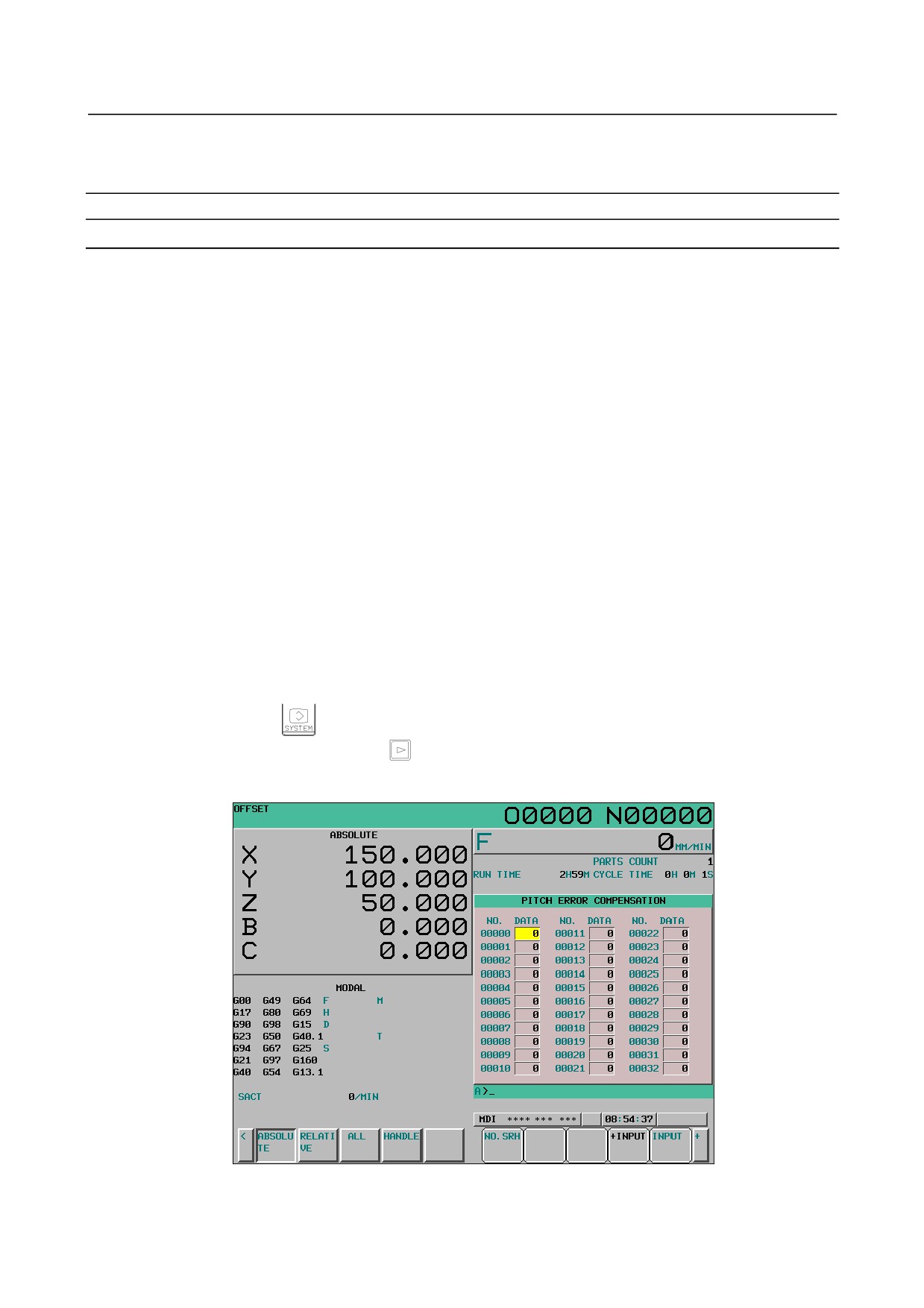
([PITCH] for the 8.4-inch display unit). The following screen is displayed:
Fig. 12.4.2 (a) PITCH ERROR COMPENSATION screen (10.4-inch)
4
Move the cursor to the compensation point number to be set in either of the following ways:
- 606 -
B-64304EN/02
OPERATION 12.SETTING AND DISPLAYING DATA
•
Enter the compensation point number and press the soft key [NO.SRH].
•
Move the cursor to the compensation point number using the page keys,
and
, and
cursor keys,
,
,
, and
5
Enter a value with numeric keys and press soft key [INPUT] in MDI mode.
NOTE
To use pitch error compensation, set bit 0 (NPE) of parameter No. 8135 to 0.
12.4.3 Servo Setting
Enter the machine constants required for servo setting for calculation within the CNC to set the
corresponding CNC parameters automatically. Simple help on the item at the cursor position is
displayed.
Procedure for servo parameter setting
Procedure
1
Set bit 0 (SVS) of parameter No. 3111 to 1 to display servo setting and tuning screens.
2
Press function key
, continuous menu key
, and soft key [SERVO SETTING] ([SV.SET]
for the 8.4-inch display unit) in this order.
4
Press soft key [SERVO SETTING] to select the servo setting screen.
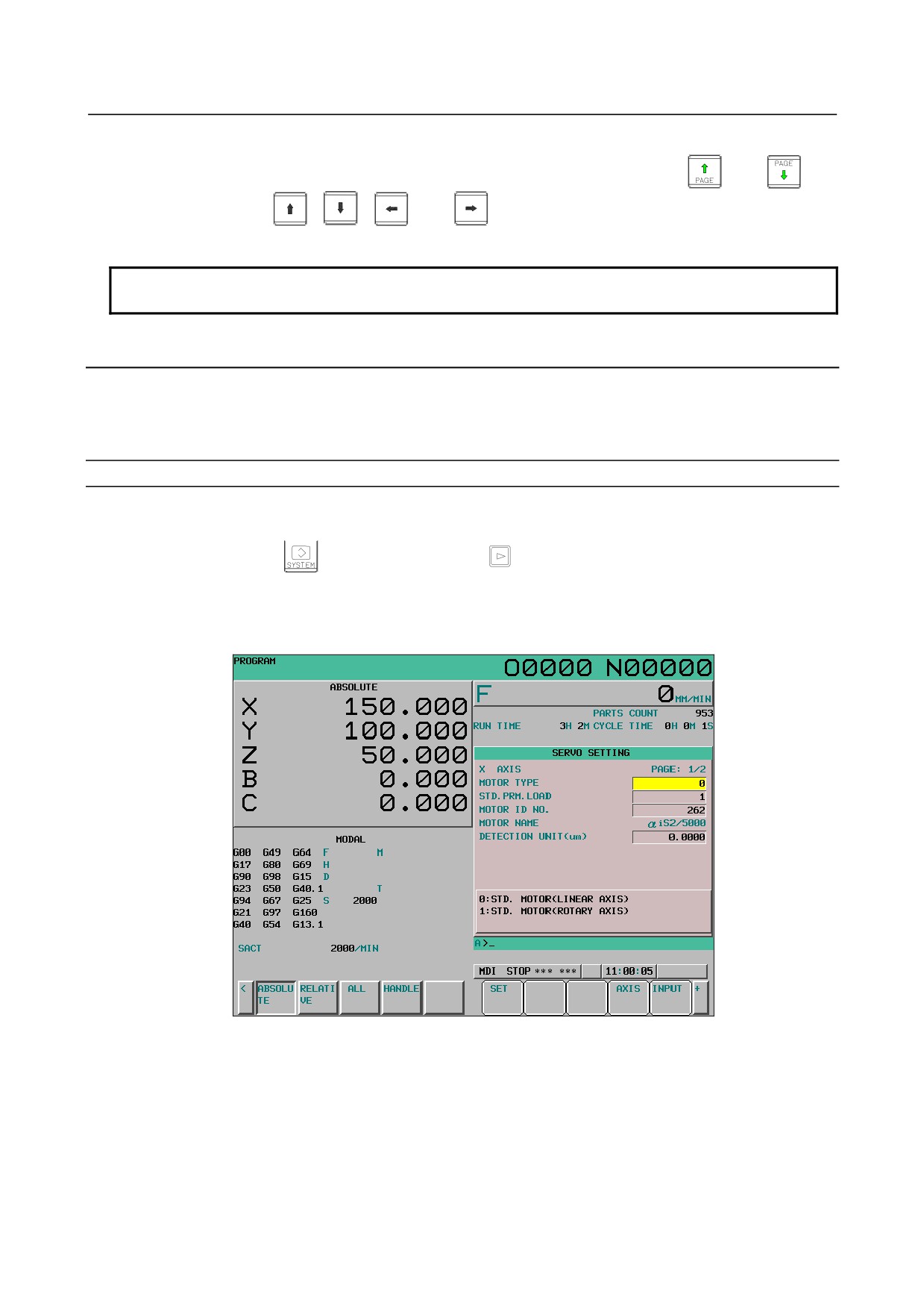
The following screen appears:
Fig. 12.4.3 (a) Servo parameter setting screen (10.4-inch)
4
Press soft key [AXIS] and select the axis to be set or changed.
5
Move the cursor to the data to be set or changed using the page keys and cursor keys.
6
Key in a setting and press soft key [INPUT] or MDI key [INPUT].
7
Set all items and press soft key [SET].
When data is set successfully, soft key [SET] is hidden. When data is changed, soft key [SET]
appears again.
- 607 -
12.SETTING AND DISPLAYING DATA OPERATION
B-64304EN/02
Entering special data
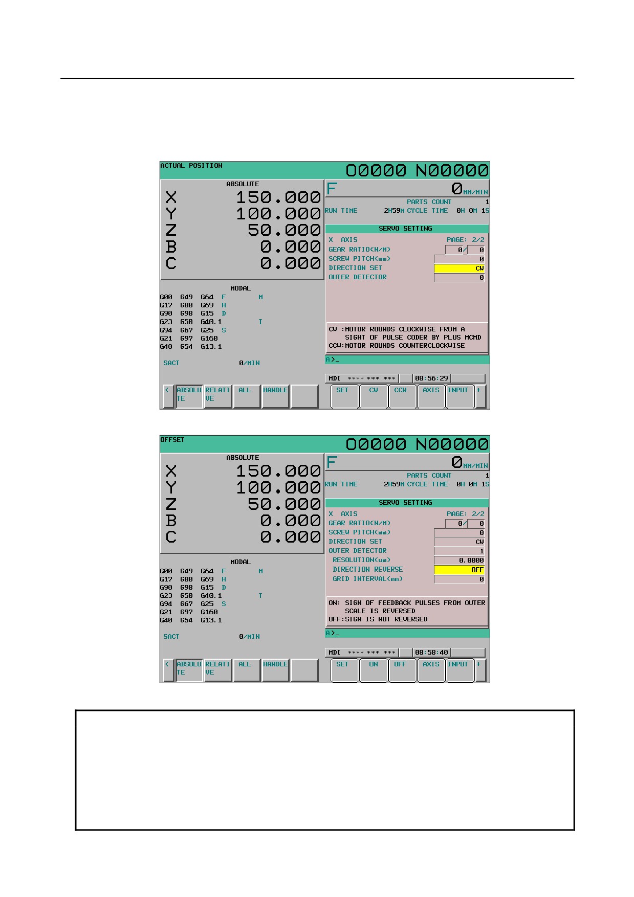
The settings of DIRECTION SET and DIRECTION REVERSE are entered with soft keys.
Move the cursor to the item to be set and press the soft key of the data to be set.
When soft key [(OPRT)] is displayed, press [(OPRT)] to display the soft keys of the data to be set.
Fig. 12.4.3 (b) Servo setting screen (DIRECTION SET) (10.4-inch)
Fig. 12.4.3 (c) Servo setting screen (DIRECTION REVERSE) (10.4-inch)
NOTE
1 The DIRECTION SET item becomes blank " " if its corresponding parameter is
set to an undefined value.
2 It is also possible to input data with numeric keys and then press soft key
[INPUT] or MDI key [INPUT].
The soft keys to be displayed and their values are shown below.
- CW:
1,
CCW:
0
- ON:
1,
OFF:
0
- 608 -
B-64304EN/02
OPERATION 12.SETTING AND DISPLAYING DATA
Setting data
When all items are set and soft key [SET] is pressed, the CNC sets the CNC parameters to the calculated
results.
When a setting is illegal
If a CNC parameter falls outside the setting range as a result of CNC internal calculation based on each
setting, the cursor moves to the DETECTION UNIT item and a warning saying "ILLEGAL SETTING
DATA" is issued.
Enter an detection unit that can be set and press soft key [SET] again.
Setting a detection unit automatically
When the cursor is placed on the DETECTION UNIT item, soft key [AUTO] appears. The detection
unit can be set automatically by pressing soft key [AUTO].
The detection unit to be set automatically is calculated based on the settings of other items and the values
of the parameters fall within the setting ranges.
Fig. 12.4.3 (d) Soft keys for selection of a detection unit (10.4-inch)
NOTE
1 When the detection unit setting is 0, the detection unit is set to 1.0000 or 0.1000.
If bit 1 (ISC) of parameter No. 1013 is 1, the detection unit is 0.1000.
2 For an axis for which bit 3 (DIA, direct specification) of parameter No. 1006 is set
to 1, the detection unit is set to half the setting value (detection unit of a radius).
(Only for the T series)
Displaying the servo setting screen for inputting parameters
Press soft key [(OPRT)] and press continuous menu key
to display soft key [CHANGE].
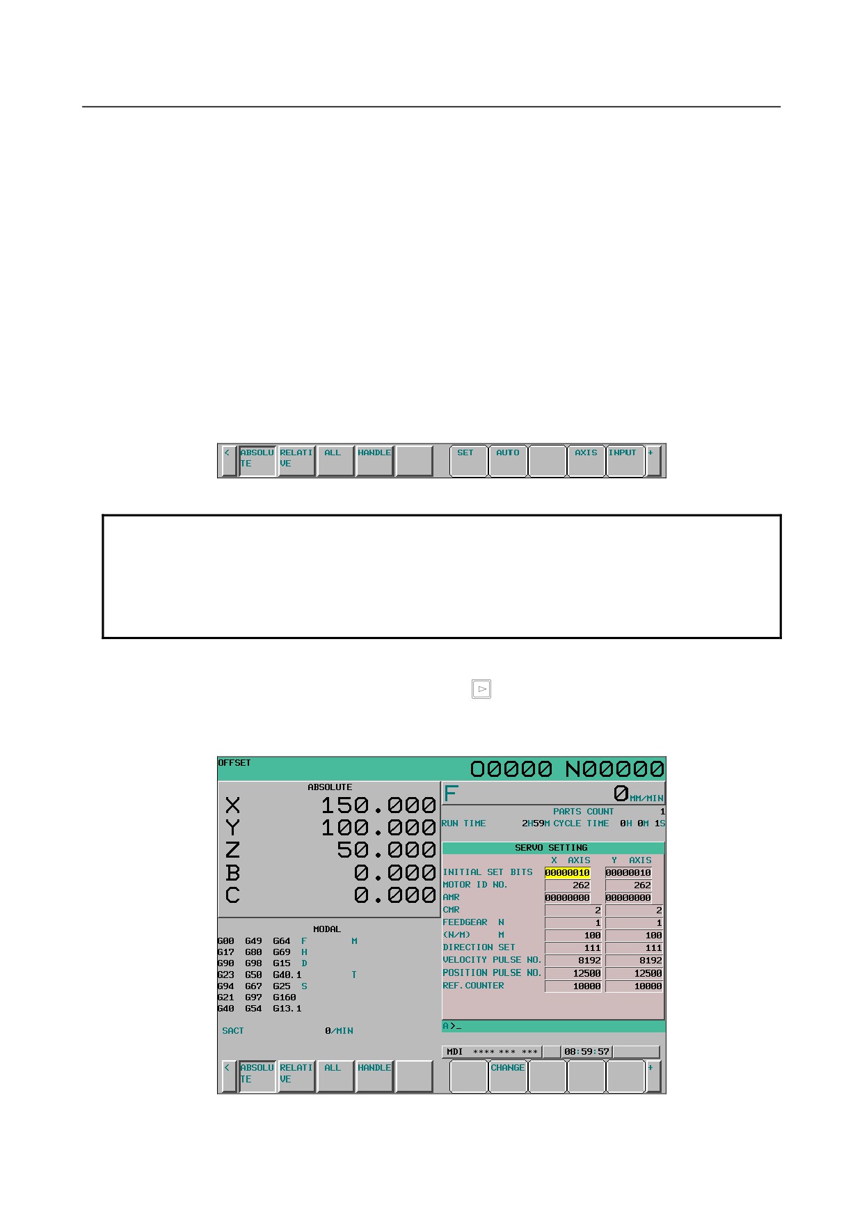
Press soft key [CHANGE] to display the servo setting screen for inputting parameters. At this time, the
screen for the axis to be set appears and the cursor moves to the first item.
Fig. 12.4.3 (c) Servo setting screen for inputting parameters (10.4-inch)
- 609 -
12.SETTING AND DISPLAYING DATA OPERATION
B-64304EN/02
To display the servo setting screen for inputting machine constants again, press soft key [CHANGE] in
the same procedure. At this time, the servo setting screen for inputting machine constants is displayed
with the axis selected by the cursor on the servo setting screen for inputting parameters specified as the
target axis.
To prevent the servo setting screen for inputting machine constants from being displayed, set bit 2 (SVO)
of parameter No. 13117 to 1.
12.4.4 Servo Tuning
Data related to servo tuning is displayed and set.
Procedure for servo tuning
Procedure
1
Set bit 0 (SVS) of parameter No. 3111 to 1 to display servo setting and tuning screens.
2
Press function key
, continuous menu key
, and soft key [SERVO SETTING] ([SV.SET]
for the 8.4-inch display unit) in this order.
3
Press soft key [SERVO TUNE] ([SV.TUN] for the 8.4-inch display unit) to select the servo tuning
screen.
The following screen appears:
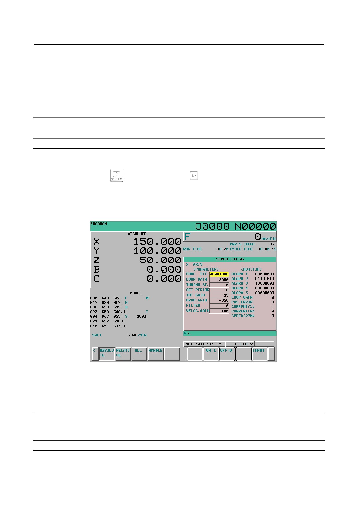
Fig. 12.4.4 (a) Servo tuning screen (10.4-inch)
4
With the page keys and cursor keys, move the cursor to the position of data to be set or modified.
5
Key in a desired value then press soft key [INPUT].
12.4.5 Spindle Setting
The machine constants required to start a spindle are input to perform calculation by the CNC. When
the CNC is restarted, the parameters required to start the spindle are set.
Setting spindle parameters
Procedure
1
Set bit 1 (SPS) of parameter No. 3111 to 1 to display spindle setting and tuning screens.
- 610 -
B-64304EN/02
OPERATION 12.SETTING AND DISPLAYING DATA
2
Press function key
, continuous menu key
, then soft key [SPINDL SETING]([SP.SET]
for the 8.4-inch display unit).
3
Press soft key [SPINDL SETING] to select the spindle setting screen.
The following screen appears:
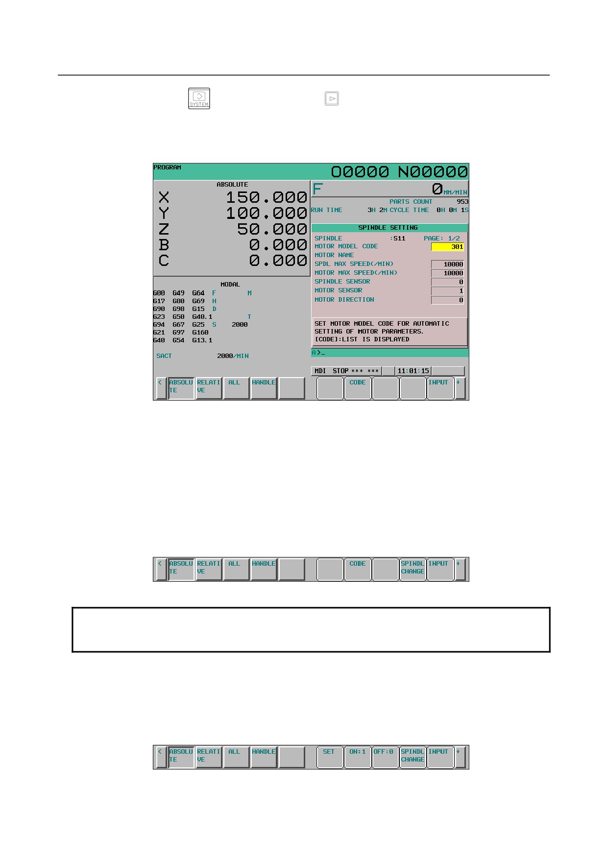
Fig. 12.4.5 (a) Spindle setting screen for entering machine constants (10.4-inch)
4
With the page keys and cursor keys, move the cursor to the position of data to be set or modified.
5
Key in the setting and press soft key [INPUT] or MDI key [INPUT].
6
After the all machine constants required to start a spindle are input, press soft key [SET]. A
necessary parameter is calculated by this operation. After the calculation ends, the parameters
required to start the spindle are set by the CNC is restarted.
Changing the spindle to be set
Press soft key [(OPRT)] to display soft key [SPINDL CHANGE] ([SP.CHG] for the 8.4-inch display
unit). Soft key [SPINDL CHANGE] is used to change the spindle to be set. Press soft key [SPINDL
CHANGE] several times to select the spindle to be set.
Fig. 12.4.5 (b) Spindle change soft keys (10.4-inch)
NOTE
When multiple serial spindles are not connected, soft key [SP.CHG] is not
displayed.
Input by soft keys
The settings of MOTOR SENSOR, PROXIMITY SWITCH EDGE, MOTOR DIRECTION, and POS.
CODER DIRECTION are made by soft keys. When the cursor is moved to the item to be set, the
following soft keys are displayed. Press the soft key for the data to be set to input data.
When soft key [(OPRT)] is displayed, press [(OPRT)] to display the soft keys for the data to be set.
Fig. 12.4.5 (c) Soft keys displayed for MOTOR SENSOR and PROXIMITY SWITCH EDGE (10.4-inch)
- 611 -
12.SETTING AND DISPLAYING DATA OPERATION
B-64304EN/02
Fig. 12.4.5 (d) Soft keys displayed for MOTOR DIRECTION and POS. CODER DIRECTION (10.4-inch)
NOTE
It is also possible to input data with numeric keys and press soft key [INPUT] or
MDI key [INPUT] to enter them.
The soft keys to be displayed and their corresponding values are shown below.
- ON:
1,
OFF:
0
- OPPST:
1,
SAME:
0
Input from a list of motor model codes
The data of MOTOR MODEL CODE can be input on the motor model code list screen. The motor
model code list screen appears when soft key [CODE] is pressed. Soft key [CODE] appears when the
cursor is placed on the MOTOR MODEL CODE item.
To return from the motor model code list screen to the previous screen, press soft key [RETURN].
Fig. 12.4.5 (e) Soft keys displayed for MOTOR MODEL CODE (10.4-inch)
Fig. 12.4.5 (f) Soft keys displayed on the motor model code list screen (10.4-inch)
When the motor model code list screen is displayed, motor model codes and their corresponding motor
names and amplifier names are listed. When the cursor is moved to the code number to be set and soft
key [SELECT] is pressed, input is completed. Upon completion of input, the previous screen is
displayed.
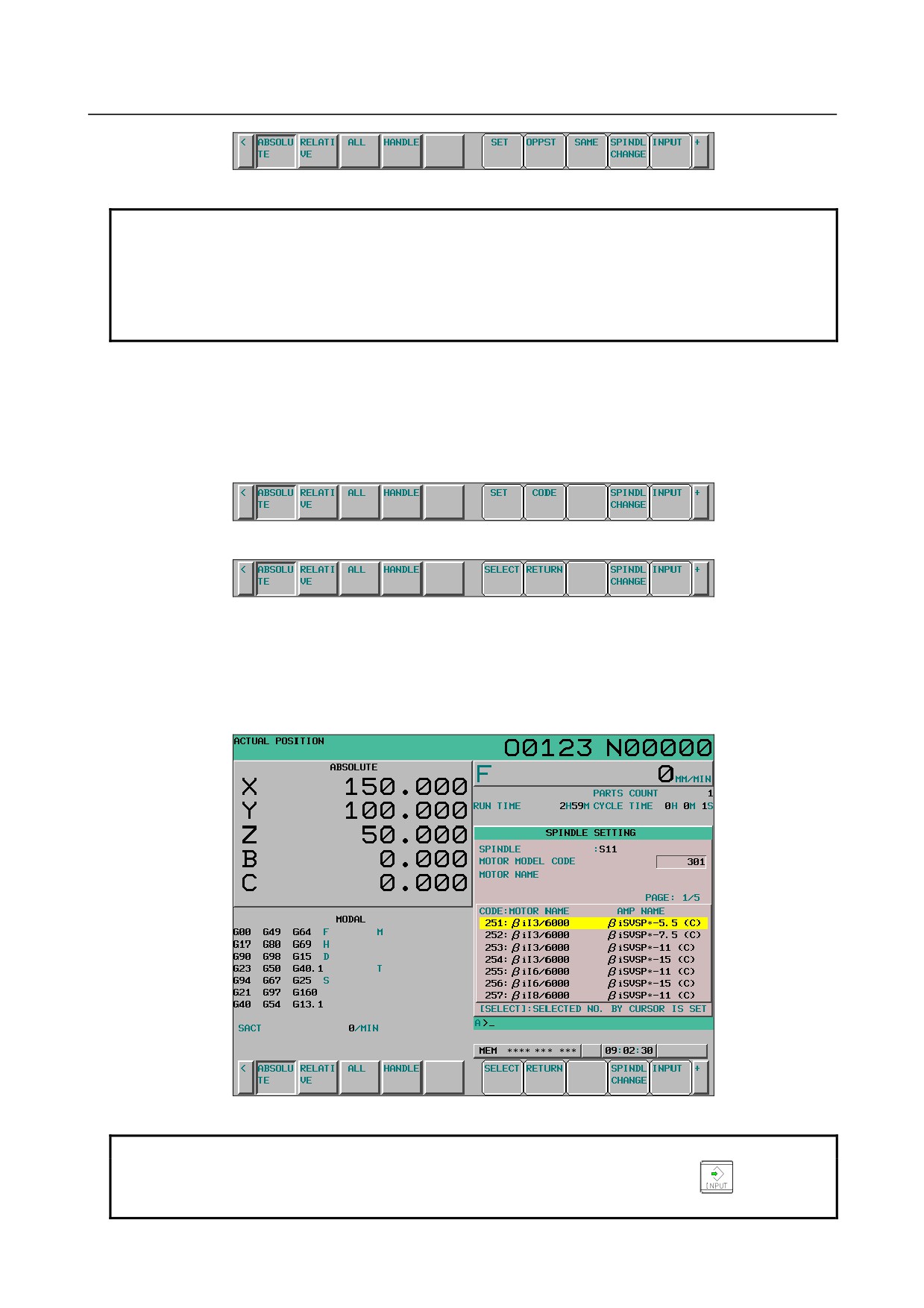
Fig. 12.4.5 (g) Motor model code list screen (10.4-inch)
NOTE
To input a motor model code not listed, press soft key [INPUT] or
key on
the MDI panel and input the motor model code.
- 612 -
B-64304EN/02
OPERATION 12.SETTING AND DISPLAYING DATA
Displaying the spindle setting screen for inputting parameters
Press soft key [(OPRT)] and continuous menu key
to display soft key [CHANGE].
Press soft key [CHANGE] to display the spindle setting screen for inputting parameters. At this time,
the spindle to be set is displayed with the cursor placed at the beginning.
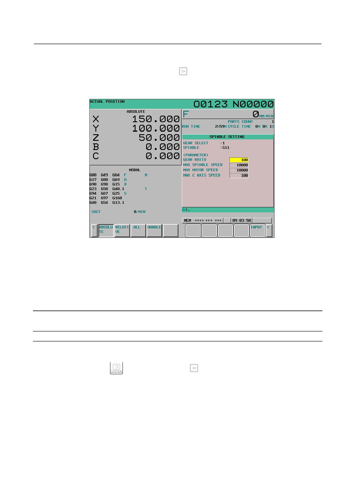
Fig. 12.4.5 (h) Spindle setting screen for inputting parameters (10.4-inch)
To display the spindle setting screen for inputting machine constants again, press soft key [CHANGE] in
the same procedure. At this time, the target is the spindle displayed on the spindle setting screen for
inputting parameters with the cursor placed at the beginning.
To prevent the spindle setting screen for inputting machine constants from being displayed, set bit 2
(SDO) of parameter No. 13118 to 1.
12.4.6 Spindle Tuning
Spindle tuning data is displayed and set.
Setting for spindle tuning
Procedure
1
Set bit 1 (SPS) of parameter No. 3111 to 1 to display spindle setting and tuning screens.
2
Press function key
, continuous menu key
, then soft key [SPINDL SETING]([SP.SET]
for the 8.4-inch display unit).
3
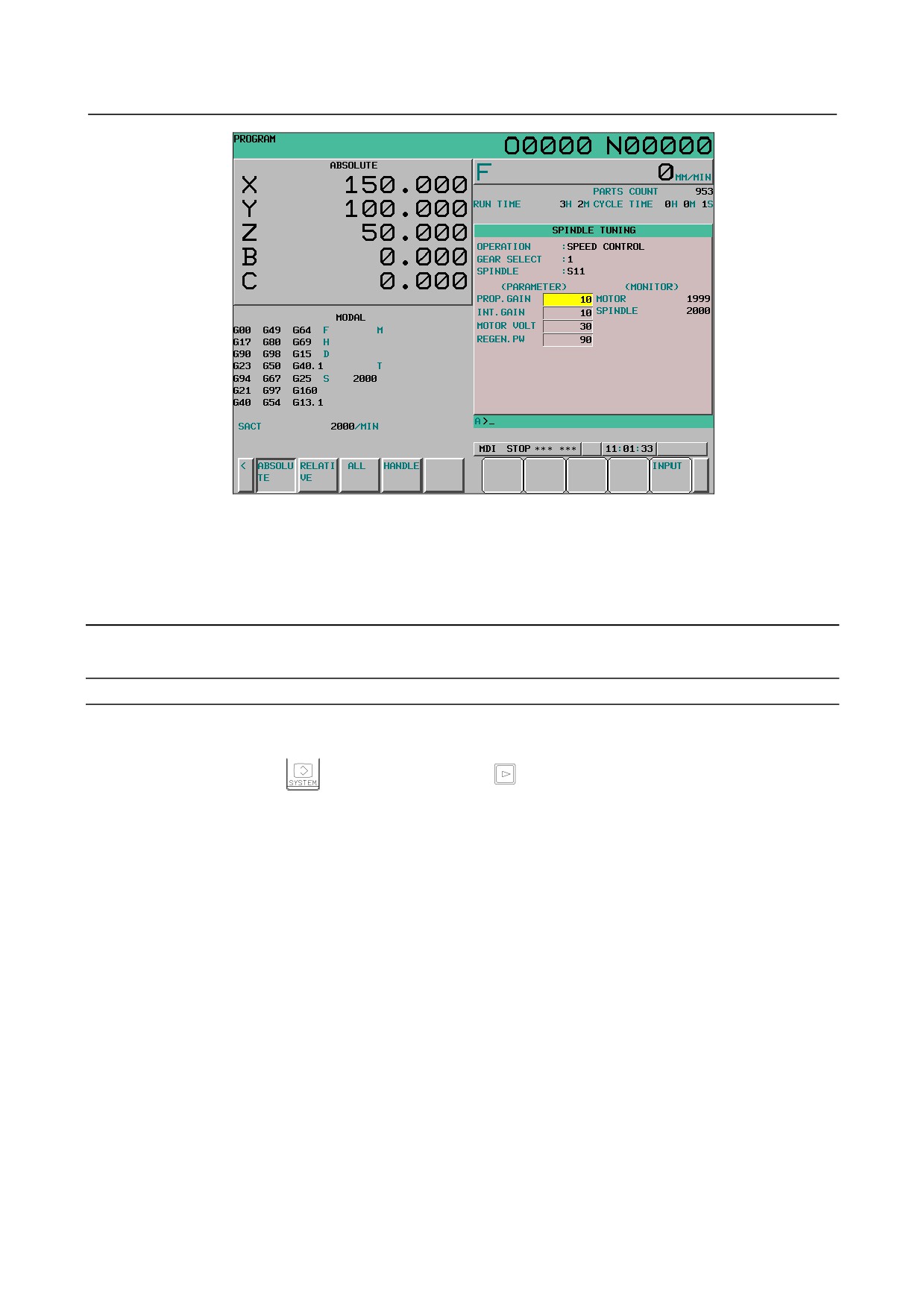
Press soft key [SPINDL TUNE] ([SP.TUN] for the 8.4-inch display unit) to select the spindle tune
screen.
4
The following screen appears:
- 613 -
12.SETTING AND DISPLAYING DATA OPERATION
B-64304EN/02
Fig. 12.4.6 (a) Spindle tuning screen (10.4-inch)
5
With the page keys and cursor keys, move the cursor to the position of data to be set or modified.
6
Key in a desired value then press soft key [INPUT].
12.4.7 Spindle Monitor
Spindle-related data is displayed.
Displaying the spindle monitor
Procedure
1
Set bit 1 (SPS) of parameter No. 3111 to 1 to display spindle setting and tuning screens.
2
Press function key
, continuous menu key
, then soft key [SPINDL SETING]([SP.SET]
for the 8.4-inch display unit).
3
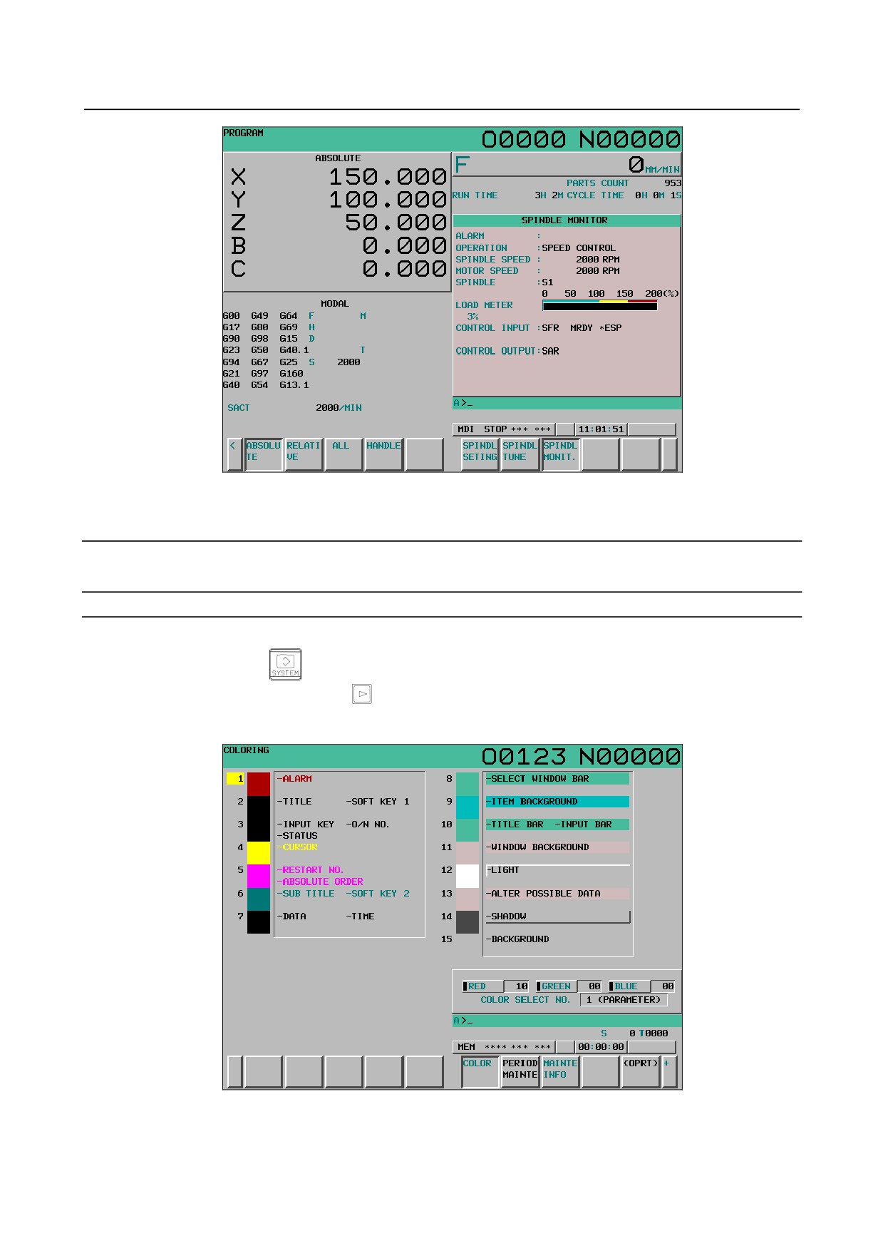
Press soft key [SPINDL MONIT.] ([SP.MON] for the 8.4-inch display unit) to select the spindle
monitor screen.
4
The following screen appears:
- 614 -
B-64304EN/02
OPERATION 12.SETTING AND DISPLAYING DATA
Fig. 12.4.7 (a) Spindle monitor screen (10.4-inch)
12.4.8 Color Setting Screen
Screen colors can be set on the color setting screen.
Displaying the color setting screen
Procedure
1
Press function key
2
Press the continuous menu key
several times to display soft key [COLOR].
3
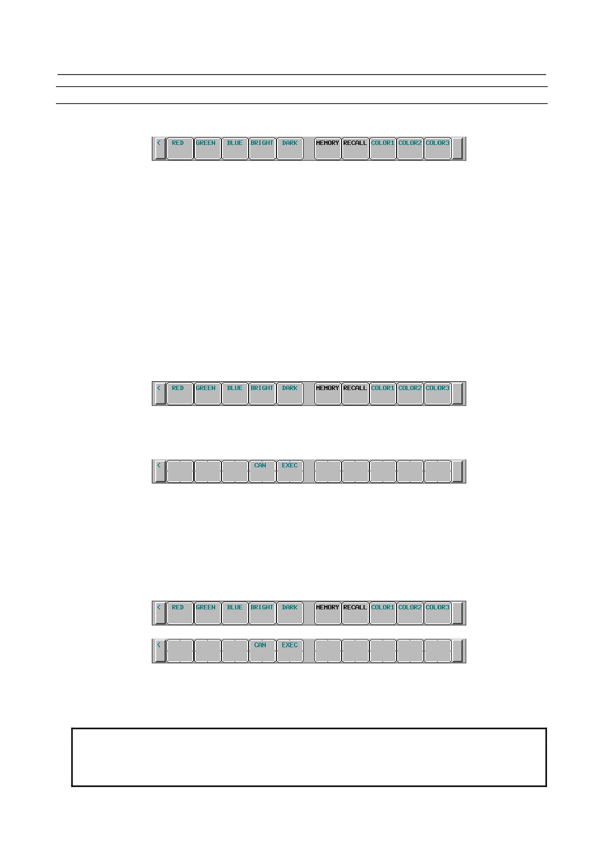
Press soft key [COLOR] to display the color setting screen.
Fig. 12.4.8 (a) Color setting screen (10.4-inch)
- 615 -
12.SETTING AND DISPLAYING DATA OPERATION
B-64304EN/02
Procedure for operating the color setting screen
-
Modifying the color (color palette values)
1
Press soft key [(OPRT)]. The soft key display changes to the following operation soft keys:
2
Move the cursor to a color number whose color palette values are to be modified.
The current color palette value set for each primary color is displayed.
3
Select a primary color whose setting is to be modified, with the corresponding operation soft key
[RED], [GREEN], or [BLUE].
More than one primary color can be selected at the same time.
Each time operation soft key [RED], [GREEN], or [BLUE] is pressed, the operation soft key toggles
between selection and deselection.
(When operation soft keys [RED], [GREEN], and [BLUE] are not displayed, press the rightmost soft
key to display the operation soft keys.)
4
Select operation soft key [BRIGHT] or [DARK] to modify the brightness of the selected prime
color(s).
-
Storing the color (color palette values)
The set color palette values can be stored.
1
Press operation soft key [COLOR1], [COLOR2], or [COLOR3] to select a storage area.
(When operation soft keys [COLOR1], [COLOR2], and [COLOR3] are not displayed, press the
rightmost soft key to display the operation soft keys.)
COLOR1
Standard color data parameters Nos. 6581 to 6595
COLOR2
Parameters Nos. 10421 to 10435
COLOR3
Parameters Nos. 10461 to 10475
2
Press operation soft key [MEMORY]. The operation soft key display switches to the following:
3
Pressing operation soft key [EXEC] stores the current color palette settings in the selected area.
Pressing operation soft key [CAN] or the leftmost key does not store the current color palette
settings in the selected area.
-
Calling the color (color palette values)
1
Press operation soft key [COLOR1], [COLOR2], or [COLOR3] to select a storage area where color
palette values are stored.
(When operation soft keys [COLOR1], [COLOR2], and [COLOR3] are not displayed, press the
rightmost soft key to display the operation soft keys.)
2
Press operation soft key [RECALL]. The operation soft key display switches to the following:
3
Pressing operation soft key [EXEC] calls the color palette values from the selected area to enable the
color to be modified. This operation is invalid if no color palette values are stored.
Pressing operation soft key [CAN] or the leftmost key does not call the color palette values from the
selected area.
NOTE
1 Immediately after the power is turned on, the settings of COLOR1 (parameters)
are used for display. If nothing is stored for COLOR1, the default colors are used
for display.
- 616 -

B-64304EN/02
OPERATION 12.SETTING AND DISPLAYING DATA
NOTE
2 Do not modify the color setting data parameters directly by MDI key input. When
modifying the standard color data, be sure to perform a storage operation on the
color setting screen.
12.4.9 Machining Parameter Tuning
12.4.9.1 Machining parameter tuning (AI contour)
In advanced preview control, AI advanced preview control, and AI contour control, by setting a
velocity-emphasized parameter set and precision-emphasized parameter set and setting the precision level
matching a machining condition such as rough machining or finish machining on the precision level
setting screen or by programming, the parameters suitable for the condition can be automatically
calculated to perform machining.
On this screen, the parameter sets for emphasis on velocity (precision level 1) and emphasis on precision
(precision level 10) can be set.
Set the following parameters:
• Acceleration rate of acceleration/deceleration before interpolation
• Acceleration change time (bell-shaped)
• Allowable acceleration change value for each axis in velocity control based on acceleration change
under jerk control
• Allowable acceleration change value for each axis in acceleration change under jerk control in
successive linear interpolation operations
• Ratio of the change time of the rate of change of acceleration in smooth bell-shaped
acceleration/deceleration before interpolation
• Allowable acceleration rate
• Acceleration rate of acceleration/deceleration after interpolation
• Corner speed difference
• Maximum feedrate
• Items that can be set freely (2 items)
For details of each parameter, see the descriptions of AI contour control.
By setting bit 0 (MPR) of parameter No. 13601 to 1, this screen can be hidden.
For the method of setting a precision level, see the description of the precision level selection screen in
Subsection 12.3.10.
Procedure for machining parameter tuning
Procedure
1
Set the MDI mode.
2
Press function key
3
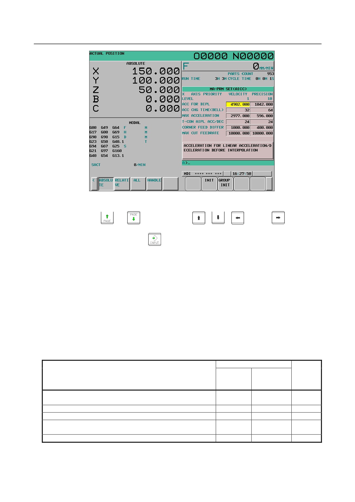
Press soft key [MCHN TUNING] ([M-TUN] for the 8.4-inch display unit) to display the machining
parameter tuning screen.
- 617 -
12.SETTING AND DISPLAYING DATA OPERATION
B-64304EN/02
Fig. 12.4.9 (a) Machining parameter tuning screen (10.4-inch)
4
Move the cursor to the position of a parameter to be set, as follows:
Press page key
or
, and cursor keys
,
,
and /or
to move the
cursor to the parameter.
5
Key in desired data then press the
key on the MDI panel.
6
When data is input, a RMS value is found according to the precision level parameters. If a RMS
value calculation fails, a warning
(indicating that automatic setting failed) is displayed The
parameters of precision level can be changed on the precision level selection screen or parameter
setting screen..
7
Repeat steps 4 and 5 until all machining parameters are set.
8
In addition to the setting method described above, a parameter setting method using soft keys is
available. Pressing soft key [INIT] displays the standard value (recommended by FANUC) of the
item selected by the cursor in the key input buffer. Pressing soft key [EXEC] initializes the item to
the standard value. Pressing soft key [GROUP INIT] ([G_INIT] for the 8.4-inch display unit)
initializes all items of a group (emphasis on velocity or emphasis on precision) selected by the cursor
to the standard values.
The table below indicates the initial settings.
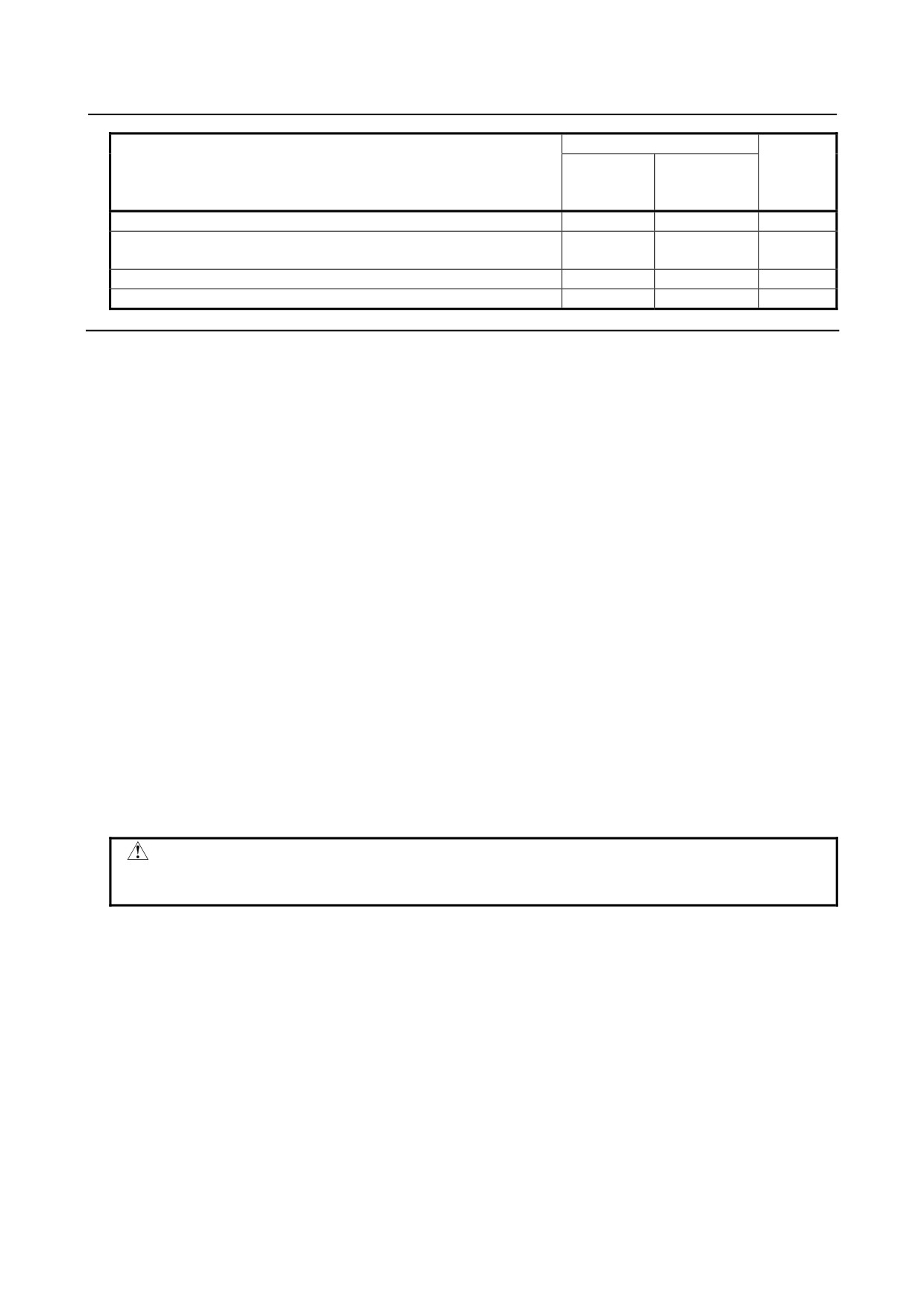
Table 12.4.9 (a) Initial settings
AI contour control
Emphasis
Emphasis on
Setting item
Unit
on velocity
precision
(LV1)
(LV10)
Acceleration rate of acceleration/deceleration before interpolation
4902.000
1042.000
mm/sec2
<ACC FOR BIPL>
Acceleration change time (bell-shaped) <ACC CHG TIME(BELL)>
32
64
msec
Allowable acceleration change value <JERK ACC DIFF>
0
0
mm/sec2
Allowable acceleration change value in successive linear interpolation
0
0
mm/sec2
operations <JERK ACC DIFF(LIN)>
Ratio of the change time of the jerk control <JERK ACC RATIO>
0
0
%
- 618 -
B-64304EN/02
OPERATION 12.SETTING AND DISPLAYING DATA
AI contour control
Emphasis
Emphasis on
Setting item
Unit
on velocity
precision
(LV1)
(LV10)
Allowable acceleration rate <MAX AACELERATION>
2977.000
596.000
mm/sec2
Time constant for acceleration/deceleration after interpolation
24
24
msec
<T-CON AIPL ACC/DEC>
Corner speed difference <CORNER FEED DIFFER>
1000
400
mm/min
Maximum cutting speed <MAX CUT FEEDRATE>
10000
10000
mm/min
Explanation
-
Look-ahead acceleration/deceleration before interpolation
Set an acceleration rate for a linear portion in look-ahead acceleration/deceleration before interpolation.
Unit of data: mm/sec2, inch/sec2, deg/sec2 (machine unit)
The parameter set on the machining parameter tuning screen is reflected in the following parameters:
Parameter No. 13610 (velocity-emphasized parameter)
Parameter No. 13611 (precision-emphasized parameter)
Moreover, the following parameter is also set according to the precision level:
Parameter No. 1660: Maximum allowable acceleration rate for each axis in acceleration/deceleration
before interpolation
-
Acceleration change time (bell-shaped)
Set a time constant for a bell-shaped portion in acceleration/ deceleration before look-ahead interpolation.
Unit of data: ms
The parameter set on the machining parameter tuning screen is reflected in the following parameters:
Parameter No. 13612 (velocity-emphasized parameter)
Parameter No. 13613 (precision-emphasized parameter)
Moreover, the following parameter is also set according to the precision level:
Parameter No. 1772: Time constant for bell-shaped look-ahead acceleration/deceleration before
interpolation of constant acceleration time type
CAUTION
A set time constant is applied to all axes. So, a modification made to this item
changes the settings for all axes.
-
Allowable acceleration change value in velocity control based on acceleration
change under jerk control
Unit of data: mm/sec2, inch/sec2, deg/sec2 (machine unit)
Set an allowable acceleration change value per ms for each axis in velocity control based on acceleration
change under jerk control.
The parameter set on the machining parameter tuning screen is reflected in the following parameters:
Parameter No. 13614 (velocity-emphasized parameter)
Parameter No. 13615 (precision-emphasized parameter)
Moreover, the following parameter is also set according to the precision level:
Parameter No. 1788:
Allowable acceleration change value for each axis in velocity control based on
acceleration change under jerk control
- 619 -
12.SETTING AND DISPLAYING DATA OPERATION
B-64304EN/02
NOTE
This setting item is displayed only when the jerk control function is enabled.
-
Allowable acceleration change value for each axis in velocity control based on
acceleration change under jerk control in successive linear interpolation
operations
Unit of data: mm/sec2, inch/sec2, deg/sec2 (machine unit)
Set an allowable acceleration change value per ms for each axis in velocity control based on acceleration
change under jerk control in successive linear interpolation operations.
The parameter set on the machining parameter tuning screen is reflected in the following parameters:
Parameter No. 13616 (velocity-emphasized parameter)
Parameter No. 13617 (precision-emphasized parameter)
Moreover, the following parameter is also set according to the precision level:
Parameter No. 1789:
Allowable acceleration change value for each axis in velocity control based on
acceleration change under jerk control in successive linear interpolation
operations
CAUTION
1 For an axis with 0 set in this parameter, the parameters (allowable acceleration
change value in velocity control based on acceleration change under jerk control:
No. 13614, No.13615) are valid.
2 For an axis with 0 set in the parameter (allowable acceleration change value in
velocity control based on acceleration change under jerk control: No. 13614,
No.13615), velocity control based on acceleration change is disabled, so that
this parameter has no effect.
NOTE
This setting item is displayed only when the jerk control function is enabled.
-
Ratio of the change time of the jerk control in smooth bell-shaped
acceleration/deceleration before interpolation
Unit of data: %
Set the ratio (in %) of the change time of jerk control to the change time of acceleration in smooth
bell-shaped acceleration/deceleration before interpolation.
The parameter set on the machining parameter tuning screen is reflected in the following parameters:
Parameter No. 13618 (velocity-emphasized parameter)
Parameter No. 13619 (precision-emphasized parameter)
Moreover, the following parameter is also set according to the precision level:
Parameter No. 1790:
Ratio of the change time of the jerk control in smooth bell-shaped
acceleration/deceleration before interpolation
NOTE
This setting item is displayed only when the jerk control function is enabled.
- 620 -
B-64304EN/02
OPERATION 12.SETTING AND DISPLAYING DATA
-
Allowable acceleration rate
Set an allowable acceleration rate in acceleration-based speed determination.
Unit of data: mm/sec2, inch/sec2, deg/sec2 (machine unit)
The parameter set on the machining parameter tuning screen is reflected in the following parameters:
Parameter No. 13620 (velocity-emphasized parameter)
Parameter No. 13621 (precision-emphasized parameter)
Moreover, the following parameter is also set according to the precision level:
Parameter No. 1735: Allowable acceleration rate for each axis applicable to the deceleration function
based on acceleration in circular interpolation
Parameter No. 1737: Allowable acceleration rate for each axis applicable to the deceleration function
based on acceleration in AI contour control
CAUTION
When bit 0 (MCR) of parameter No. 13600 is set to 1, the deceleration function
based on acceleration in circular interpolation is not set.
-
Time constant for acceleration/deceleration after interpolation
Set a time constant for acceleration/deceleration after interpolation.
Unit of data: ms
The parameter set on the machining parameter tuning screen is reflected in the following parameters:
Parameter No. 13622 (velocity-emphasized parameter)
Parameter No. 13623 (precision-emphasized parameter)
Moreover, the following parameter is also set according to the precision level:
Parameter No. 1769: Time constant for acceleration/deceleration after cutting feed interpolation
-
Corner speed difference
Set an allowable corner speed difference used for speed determination.
Unit of data: mm/sec, inch/sec, deg/sec (machine unit)
The parameter set on the machining parameter tuning screen is reflected in the following parameters:
Parameter No. 13624 (velocity-emphasized parameter)
Parameter No. 13625 (precision-emphasized parameter)
Moreover, the following parameter is also set according to the precision level:
Parameter No. 1783: Allowable speed difference for each axis in automatic corner deceleration based on
speed difference
-
Maximum cutting speed
Set a maximum cutting speed for each axis.
Unit of data: mm/sec, inch/sec, deg/sec (machine unit)
The parameter set on the machining parameter tuning screen is reflected in the following parameters:
Parameter No. 13626 (velocity-emphasized parameter)
Parameter No. 13627 (precision-emphasized parameter)
Moreover, the following parameter is also set from the precision level:
Parameter No. 1432: Maximum cutting feedrate for each axis in the AI contour control mode
- 621 -
12.SETTING AND DISPLAYING DATA OPERATION
B-64304EN/02
-
Arbitrary items
Two arbitrary parameters can be registered. Each item can correspond to a CNC parameter or servo
parameter. A parameter number corresponding to each item is to be specified with parameters.
As indicated below, set the parameters for corresponding parameter numbers, velocity-emphasized
parameters (precision level 1), and precision-emphasized parameters (precision level 10).
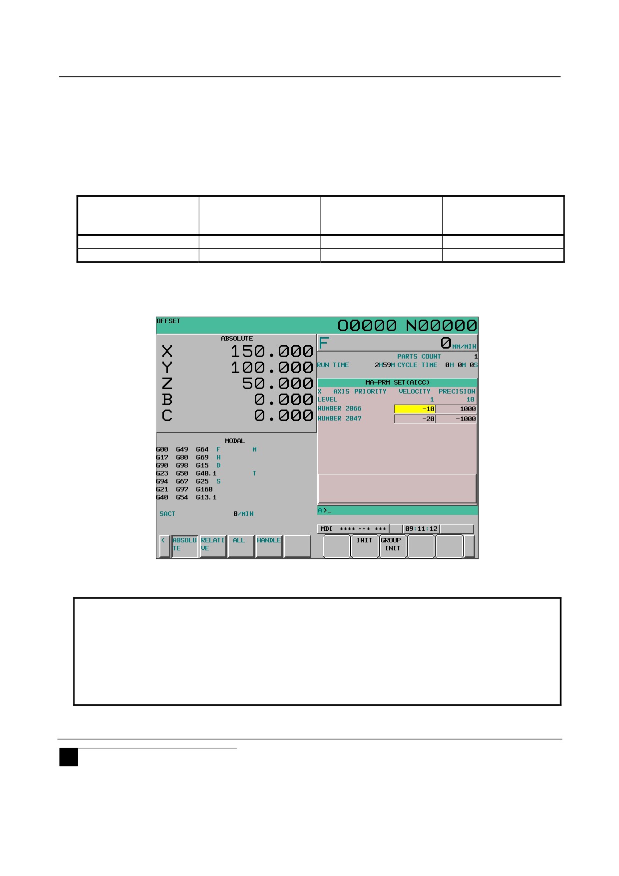
Table 12.4.9 (b) Parameters related to arbitrary items
Setting of
Setting of
Corresponding parameter
velocity-emphasized
precision-emphasized
number
(precision level 1) value
(precision level 10) value
Arbitrary item 1
No.13628
No.13630
No.13632
Arbitrary item 2
No.13629
No.13631
No.13633
• Display
Tuning target parameter numbers are displayed.
Fig. 12.4.9 (b) Machining parameter tuning screen (10.4inch)
Example of using arbitrary items
NOTE
As arbitrary items, the numbers of the following parameters cannot be specified:
• Bit parameter
• Spindle parameters (Parameter Nos. 4000 to 4799)
• Real-type parameter
• Power-off parameter
• Nonexistent parameter
12.4.9.2 Machining parameter tuning (nano smoothing) (M Series)
M
In nano smoothing, by setting a parameter set and setting the smoothing level matching a machining
condition on the smoothing level selection screen or by programming, the parameters suitable for the
condition can be automatically calculated to perform machining.
- 622 -
B-64304EN/02
OPERATION 12.SETTING AND DISPLAYING DATA
On this screen, the parameter sets for emphasis on precision (smoothing level 1) and emphasis on surface
smoothing (smoothing level 10) can be set.
Set the following parameters:
• Tolerance
For details of each parameter, see the descriptions of nano smoothing.
By setting bit 0 (MPR) of parameter No. 13601 to 1, this screen can be hidden.
For the method of setting a smoothing level, see the description of the smoothing level selection screen.
NOTE
These setting items are displayed only when machining quality level adjustment
is enabled.
Procedure for machining parameter tuning
1
Set the MDI mode.
2
Press function key
3
Press soft key [MCHN TUNING].
4
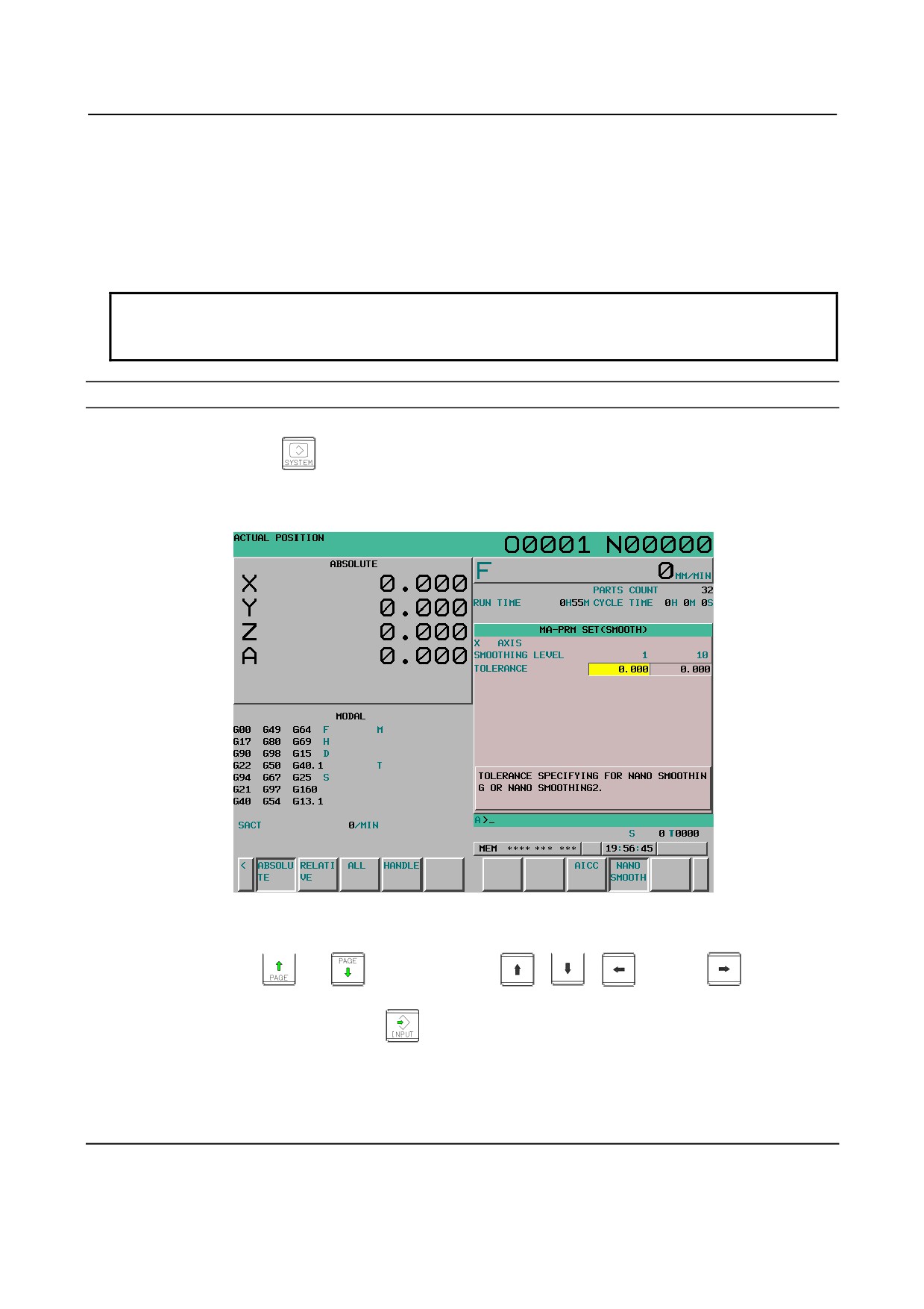
Press soft key [NANO SMOOTH] to display the machining parameter tuning screen.
Fig. 12.4.9.2 (a) Machining parameter tuning screen (nano smoothing)
5
Move the cursor to the position of a parameter to be set, as follows:
Press page key
or
, and cursor keys
,
,
and /or
to move the
cursor to the parameter.
6
Key in desired data then press the
key on the MDI panel.
7
When data is input, a RMS value is found according to the smoothing level parameters. (The
smoothing level can be changed on the smoothing level selection screen or parameter setting screen.)
If a RMS value calculation fails, a warning (indicating that automatic setting failed) is displayed.
8
Repeat steps 5 and 6 until all machining parameters are set.
Explanation
-
Tolerance
Set the value specified for the tolerance for nano smoothing.
- 623 -
12.SETTING AND DISPLAYING DATA OPERATION
B-64304EN/02
Unit of data: mm, inch, degree (input unit)
The parameter set on the machining parameter tuning screen (smoothing) is reflected in the following
parameters:
Parameter No. 11682 (smoothing level 1)
Parameter No. 11683 (smoothing level 10)
Moreover, the following parameter is also set according to the smoothing level:
Parameter No. 19541: Tolerance specified for nano smoothing
CAUTION
Since the tolerance specified for nano smoothing is common to all axes,
changing this item changes the setting for all axes.
12.4.10 Parameter Setting Support Screen
The parameter setting support screen is a screen for parameter setting and tuning designed to achieve the
following:
1
The minimum required parameters that must be set when the machine is started up are collectively
displayed to facilitate start-up of the machine.
2
The servo tuning screen, spindle tuning screen, and machining parameter setting support screen are
displayed for smooth tuning.
The parameter setting support screen consists of a menu screen and several setting screens.
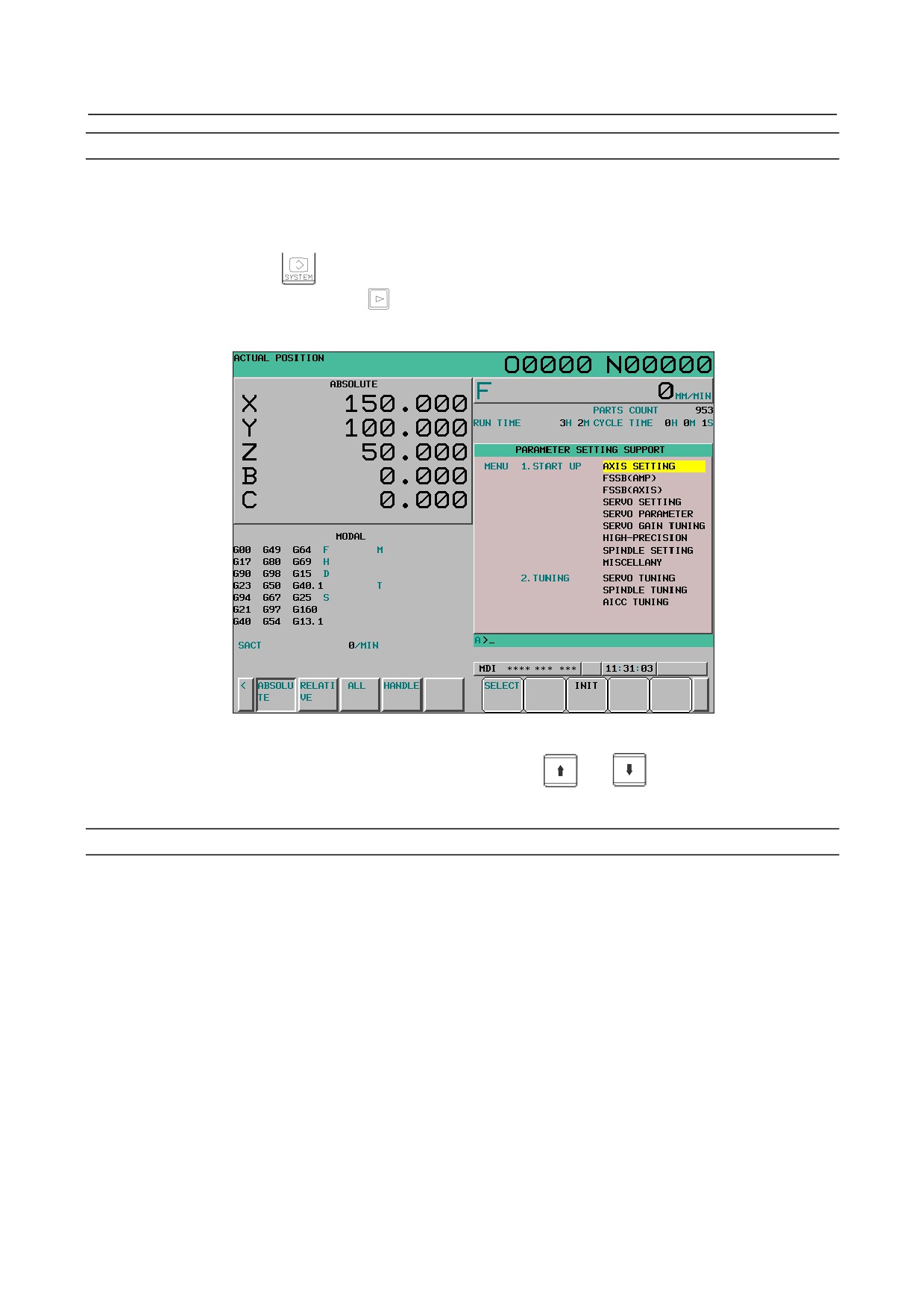
12.4.10.1 Displaying the menu screen and selecting a menu item
The parameter setting support menu screen displays the following items:
[START UP]
• AXIS SETTING
• FSSB (AMP)
• FSSB (AXIS)
• SERVO SETTING
• SERVO PARAMETER
• SERVO GAIN TUNING
• HIGH-PRECISION
• SPINDLE SETTING
• MISCELLANY
[TUNING]
• SERVO TUNING
• SPINDLE TUNING
• AICC TUNING
On the parameter setting support menu screen, one of the displayed items can be selected to display the
corresponding screen. From each setting screen, you can return to the menu screen by performing a soft
key operation.
NOTE
Some items may not be displayed, depending on the system configuration.
- 624 -
B-64304EN/02
OPERATION 12.SETTING AND DISPLAYING DATA
Displaying the menu screen and selecting a setting screen
Procedure
1
Set the MDI mode.
2
Switch the setting of "PARAMETER WRITE" to "ENABLED". For details, see the procedure for
"PARAMETER WRITE" in Subsection III-12.4.1.
3
Press function key
4
Press the continuous menu key
several times.
5
Press soft key [PARAMETER] ([PRMSET] for the 8.4-inch display unit) to display the menu screen
for parameter setting support.
Fig. 12.4.10.1 (a) Menu screen for parameter setting support (10.4-inch)
6
Move the cursor to a desired item by pressing cursor key
or
7
Press soft key [SELECT]. The screen display switches to the selected screen.
Returning to the menu screen
Procedure
1
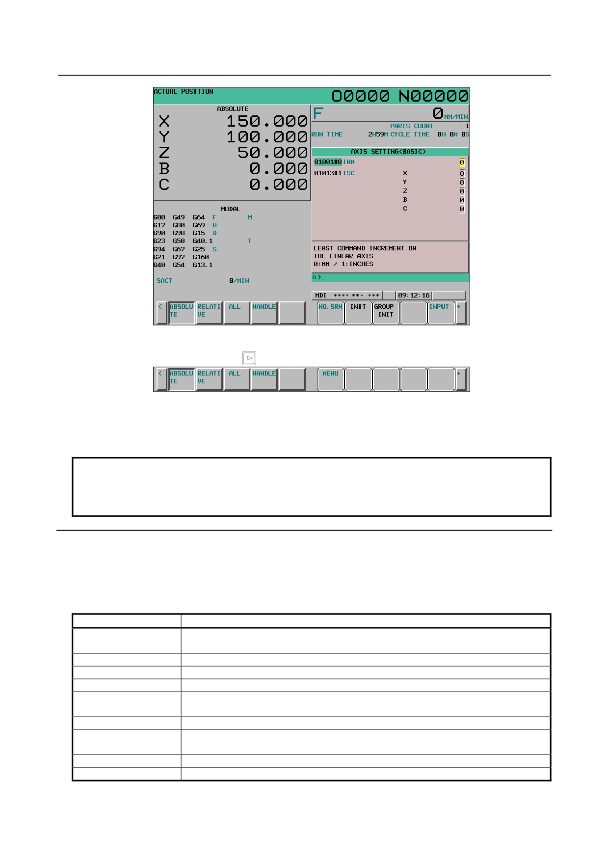
Press soft key [SELECT] on the parameter setting support menu screen. The screen and soft keys
shown below are displayed. (The screen below is displayed when "AXIS SETTING" is selected.)
- 625 -
12.SETTING AND DISPLAYING DATA OPERATION
B-64304EN/02
Fig. 12.4.10.1 (b) Axis setting screen (10.4-inch)
2
Press the continuous menu key
several times.
3
Press soft key [MENU].
The screen display returns to the parameter setting support menu screen.
4
Upon completion of parameter setting, switch the setting of "PARAMETER WRITE" to
"DISABLED".
NOTE
Some setting screens can also be displayed by a chapter selection soft key. If a
screen is selected using a chapter selection soft key, however, you cannot return
to the parameter setting support menu screen.
Explanation
-
Items displayed with [START UP]
The items of [START UP] indicate the screens for setting the minimum required parameters for starting
up the machine.
Table 12.4.10.1 (a) Items displayed with [START UP]
Display item
Description
Sets the CNC parameters of axes, spindles, coordinates, feedrates, and
AXIS SETTING
acceleration/deceleration.
FSSB (AMP)
Displays the FSSB amplifier setting screen.
FSSB (AXIS)
Displays the FSSB axis setting screen.
SERVO SETTING
Displays the servo setting screen.
SERVO PARAMETER
Sets the CNC parameters of servo current control, speed control, position control, and
backlash acceleration.
SERVO GAIN TUNING
Adjusts the speed loop gain automatically.
HIGH-PRECISION
Sets the CNC parameters of servo time constants and automatic
acceleration/deceleration.
SPINDLE SETTING
Displays the spindle setting screen.
MISCELLANY
Sets the CNC parameters of axis path assignment, DI/DO, and serial spindles.
- 626 -
B-64304EN/02
OPERATION 12.SETTING AND DISPLAYING DATA
-
Items displayed with [TUNING]
The items of [TUNING] indicate the screens for servo, spindle, and high-speed high-precision machining
tuning.
Fig. 12.4.10.1 (b) Items displayed with [TUNING]
Display item
Description
SERVO TUNING
Servo tuning screen
SPINDLE TUNING
Spindle tuning screen
AICC TUNING
Machining parameter tuning screen
NOTE
Some items may not be displayed, depending on the system configuration.
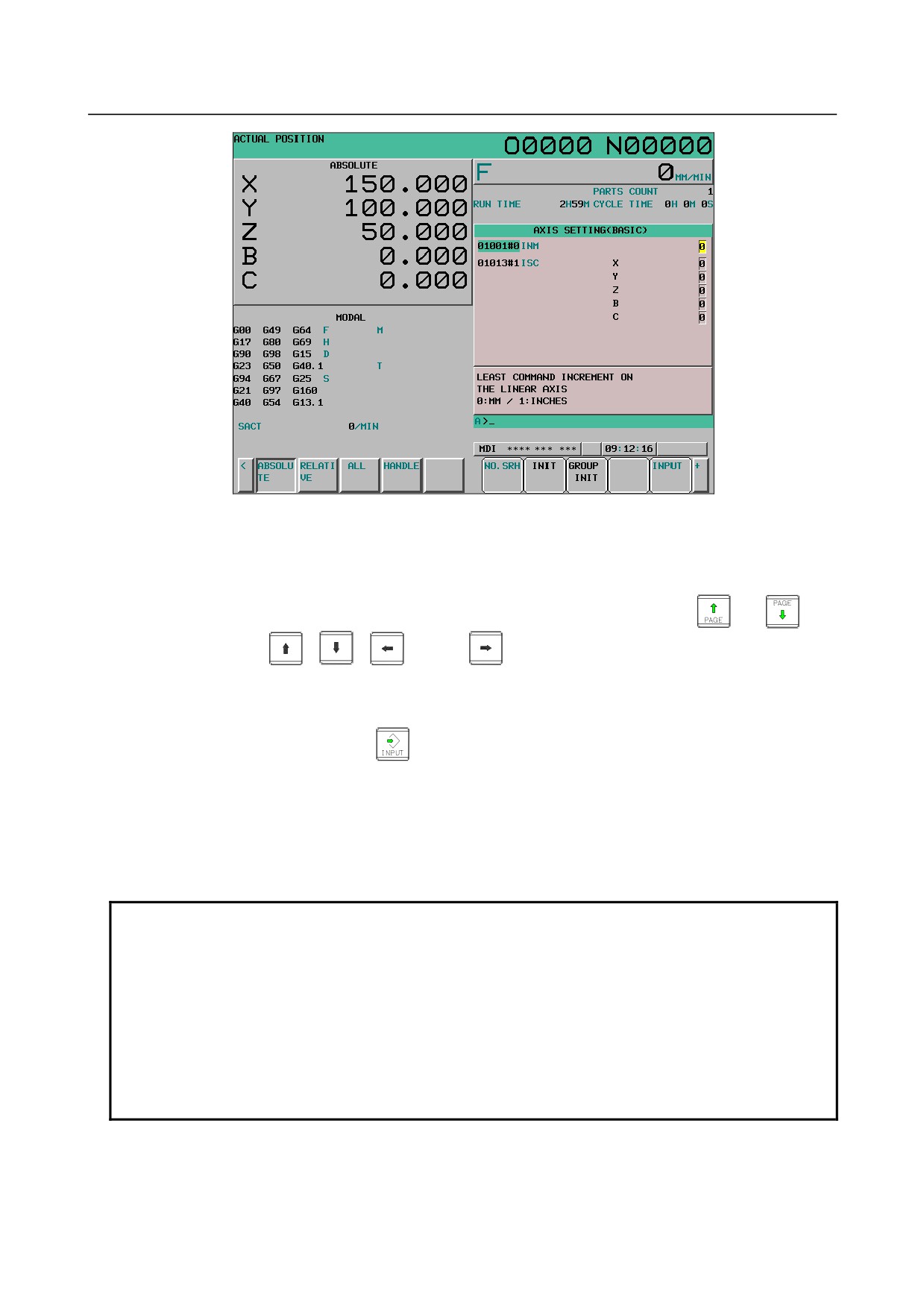
12.4.10.2 Displaying and setting the axis setting screen
This screen enables the CNC parameters related to axes, coordinates, feedrate, and
acceleration/deceleration to be displayed and set. The parameters displayed can be divided into four
groups:
(Basic) group :
The parameters related to basic settings are displayed.
(SPINDLE) group :
The parameters related to spindles are displayed.
(Coordinate) group :
The parameters related to coordinates are displayed.
(Feedrate) group :
The parameters related to feedrate are displayed.
(Acceleration/deceleration) group:
The parameters related to acceleration/deceleration are displayed.
The parameters can be initialized to the standard values (recommended by FANUC).
Display and setting
Procedure
1
Move the cursor to [AXIS SETTING] by pressing cursor key
or
on the parameter
setting support menu screen.
2
Press soft key [SELECT]. The screen display switches to the screen and soft keys shown below.
- 627 -
12.SETTING AND DISPLAYING DATA OPERATION
B-64304EN/02
Fig. 12.4.10.2 (a) Parameter setting support screen (axis setting) (10.4-inch)
3
Move the cursor to a parameter number to be set or displayed, according to one of the methods
below.
•
Enter the parameter number and press soft key [NO.SRH] .
•
Move the cursor to the desired parameter number by pressing page key
or
, and
cursor keys
,
,
, and/or
A brief description of the parameter where the cursor is placed is provided at the bottom of the
screen. However, no description is provided when the cursor is placed on multiple bits for bit
parameters.
4
Input desired data then press the
key on the MDI panel to set the parameter.
5
Press soft key [INIT]. The standard value (recommended by FANUC) for the item selected by the
cursor is displayed in the key input buffer. Pressing soft key [EXEC] in this state initializes the item
to the standard value.
6
Press soft key [GROUP INIT]([G_INIT] for the 8.4-inch display unit). A message asking whether to
set the group standard values is displayed on the screen. Pressing soft key [EXEC] in this state
inputs all of the standard values of the group.
NOTE
1 If the cursor is placed on a parameter that has no standard value assigned, no
standard value is input even when [INIT] is pressed.
2 When the cursor is placed on multiple bits for bit parameters, the multiple bits
can be input simultaneously. When [INIT] is pressed in this state, the key input
buffer displays the standard values for the bits where the cursor is placed. If a bit
has no standard value assigned, "*" is displayed for the bit, and no value is input
for the bit.
3 When [GROUP INIT]([G_INIT] for the 8.4-inch display unit) is pressed, those
parameters that have no standard values assigned are not initialized.
- 628 -
B-64304EN/02
OPERATION 12.SETTING AND DISPLAYING DATA
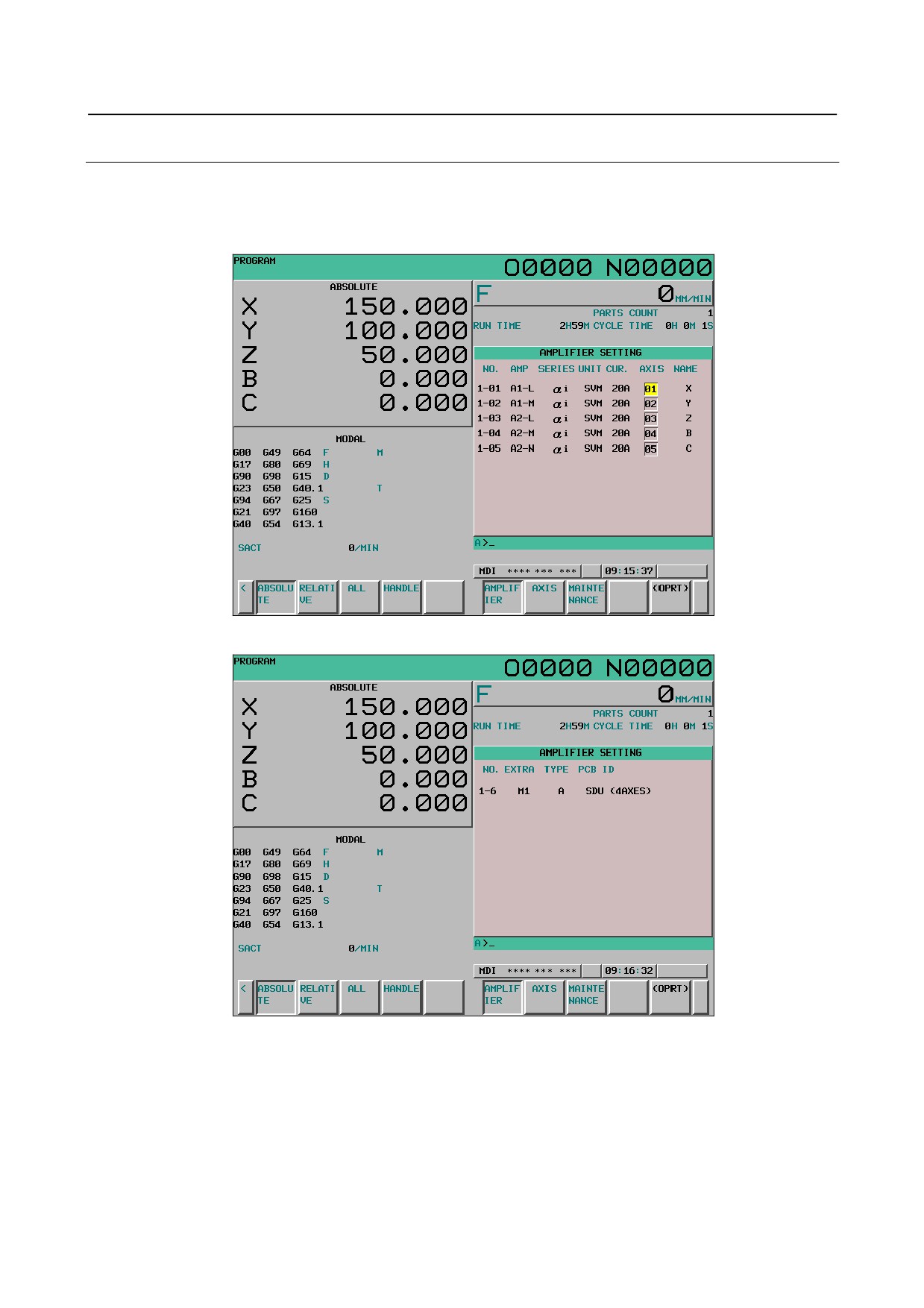
12.4.10.3 Displaying and setting the FSSB amplifier setting screen
From the parameter setting support screen, the FSSB amplifier setting screen can be displayed. For details
of the FSSB amplifier setting screen, see the description of the FSSB amplifier setting screen in
Subsection 1.4.4 in the Connection Manual (Function) (B-64303EN-1).
Fig. 12.4.10.3 (a) FSSB amplifier setting screen (10.4-inch)
Fig. 12.4.10.3 (b) FSSB amplifier setting screen 2 (10.4-inch)
- 629 -
12.SETTING AND DISPLAYING DATA OPERATION
B-64304EN/02
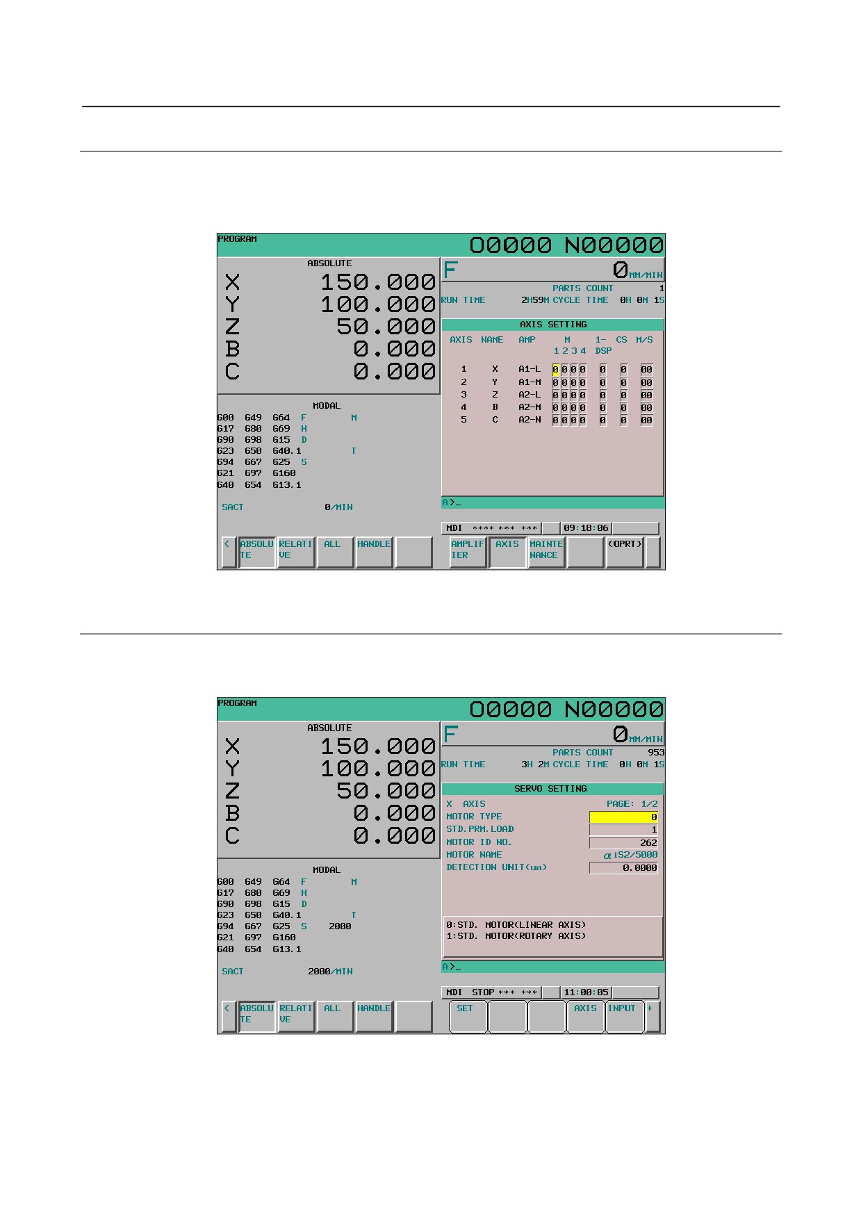
12.4.10.4 Displaying and setting the FSSB axis setting screen
From the parameter setting support screen, the FSSB axis setting screen can be displayed. For details of
the FSSB axis setting screen, see the description of the FSSB axis setting screen Subsection 1.4.4 in the
Connection Manual (Function) (B-64303EN-1).
Fig. 12.4.10.4 (a) FSSB axis setting screen (10.4-inch)
12.4.10.5 Displaying and setting the servo setting screen
From the parameter setting support screen, the servo setting screen can be displayed. For details of the
servo setting screen, see the description of the servo setting in Subsection III-12.4.4.
Fig. 12.4.10.5 (a) Servo setting screen (10.4-inch)
- 630 -
B-64304EN/02
OPERATION 12.SETTING AND DISPLAYING DATA
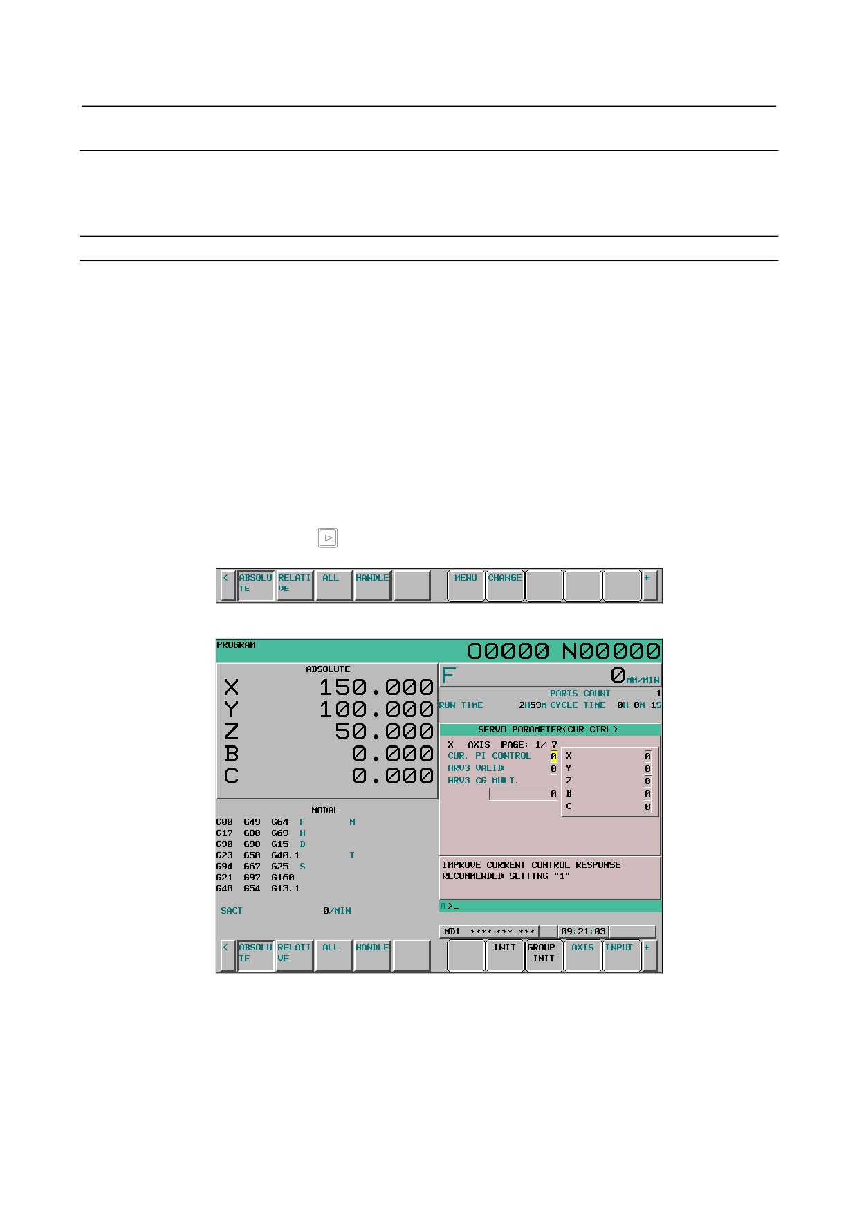
12.4.10.6 Displaying and setting the servo setting screen
Servo-related parameters can be displayed or changed.
The CNC parameters of servo current control, speed control, position control, and backlash acceleration
can be displayed or changed.
Displaying the servo parameter screen
The servo parameter screen can be displayed from the parameter setting support screen. For the display
procedure, see the parameter setting support screen (axis setting) described earlier.
Switching screen display
There are two types of screen display for the servo parameter screen.
1.
Display for each axis
The items to be set are displayed for each axis.
2.
Display for each item
Display is performed for each item to be set.
(Data of all axes is displayed for each item.)
Screen display is switched between display for each axis and display for each item each time soft key
[CHANGE] is pressed. To display soft key [CHANGE], follow the procedure below.
1.
Display the servo parameter screen.
2.
Press continuous menu key
to display soft key [CHANGE].
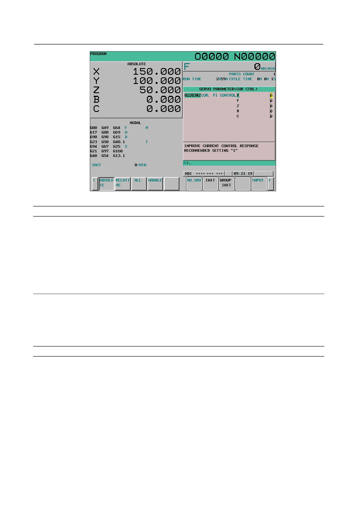
Fig. 12.4.10.6 (a) Servo parameter screen (10.4-inch)
Fig. 12.4.10.6 (b) Servo parameter screen (display for each axis) (10.4-inch)
- 631 -
12.SETTING AND DISPLAYING DATA OPERATION
B-64304EN/02
Fig. 12.4.10.6 (㨏) Servo parameter screen (display for each item) (10.4-inch)
Setting the servo parameter screen
Procedure
1
On the setting screen, confirm PARAMETER ENABLE SWITCH ON.
2
Press soft key [AXIS] several times to select the axis to be set.
3
Enter a value with numeric keys and press soft key [INPUT] or MDI key [INPUT].
The parameters can be initialized to their default values (FANUC recommended values).
(For this
procedure, see this subsection or "Parameter setting support screen (axis setting)".)
12.4.10.7 Displaying and setting the servo gain tuning screen
On the servo gain tuning screen, it is possible to adjust the following parameters automatically so that
optimum velocity gain can be set easily according to the machine characteristics.
• Load inertia ratio (parameter No. 2021)
• Velocity gain multiplier during cutting (parameter No. 2107)
• Velocity gain multiplier during high speed HRV current control (parameter No. 2335)
Displaying and setting the servo gain tuning screen
The servo gain tuning screen can be displayed from the parameter setting support screen. For the
display procedure, see "Parameter setting support screen (axis setting)" described earlier.
There are two types of screen display for the servo gain tuning screen.
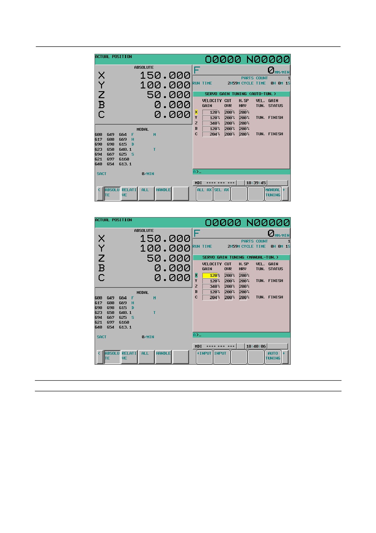
On the automatic tuning screen, servo software calculates the optimum servo loop gain of all axes or a
selected axis and automatically sets VELOCITY GAIN, CUT OVR, and H. SP HRV.
On the manual tuning screen, VELOCITY GAIN, CUT OVR, and H. SP HRV of the desired axis can be
set directly with MDI keys.
- 632 -
B-64304EN/02
OPERATION 12.SETTING AND DISPLAYING DATA
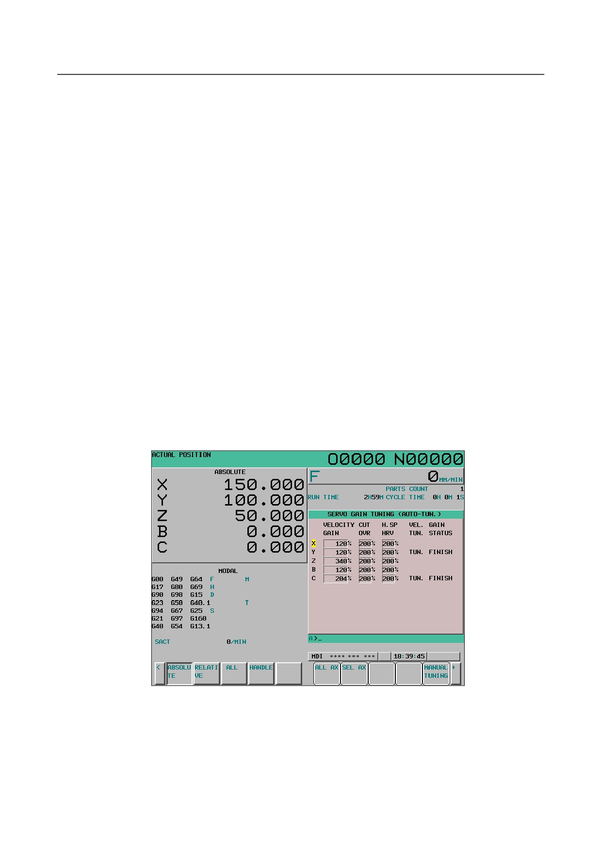
Fig. 12.4.10.7 (a) Servo gain tuning screen (automatic tuning screen) (10.4-inch)
Fig. 12.4.10.7 (b) Servo gain tuning screen (manual tuning screen) (10.4-inch)
Display item
VELOCITY GAIN
The value calculated by the CNC with the following expression on the basis of parameter No. 2021 is
displayed.
(Expression):
VELOCITY GAIN = (256 + No. 2021) / 256 × 100
CUT OVR
The setting of parameter No. 2107 is displayed.
H. SP HRV
The setting of parameter No. 2335 is displayed.
- 633 -
12.SETTING AND DISPLAYING DATA OPERATION
B-64304EN/02
VEL. GAIN TUN. STATUS
The automatic tuning status is displayed. The automatic tuning status is indicated by one of the
following four states: "tuning finished", which indicates that automatic tuning is completed, "tuning not
finished", which indicates that automatic tuning is not completed, "tuning in progress", which indicates
that automatic tuning is in progress, and "initial status error", which indicates that automatic tuning is not
completed successfully.
For the axis for which automatic tuning is completed, TUN. FINISH is displayed under VEL. GAIN TUN.
STATUS. For the axis for which automatic tuning is in progress, ON TUNING is displayed. For the
axis for which automatic tuning is not completed successfully, INIT. ERR is displayed. For the axis for
which automatic tuning is not completed, no message is displayed under VEL. GAIN TUN. STATUS.
Even when automatic tuning of an axis is completed, however, if automatic tuning is performed again, the
previous message is cleared. Therefore, if automatic tuning is interrupted, the indication becomes blank.
CNC mode when the velocity gain is set
When setting the velocity gain on the servo gain tuning screen, set PARAMETER WRITE to 1 (enabled)
on the setting screen and set the CNC in the MDI mode.
If the velocity gain is set when PARAMETER WRITE is 0, a warning saying "WRITE PROTECT" is
issued. If the velocity gain is set in other than the MDI mode, a warning saying "WRONG MODE" is
issued.
Servo gain automatic tuning screen
On the automatic tuning screen, servo software calculates the optimum servo loop gain of all axes or a
selected axis and automatically sets VELOCITY GAIN, CUT OVR, and H. SP HRV. This process is
called automatic tuning.
When soft key [ALL AX] is pressed on the automatic tuning screen, the servo loop gain of all axes is
automatically set. When [SEL AX] is pressed, the servo loop gain of the axis selected by the cursor is
automatically set. These processes are called all axis tuning and selected axis tuning, respectively.
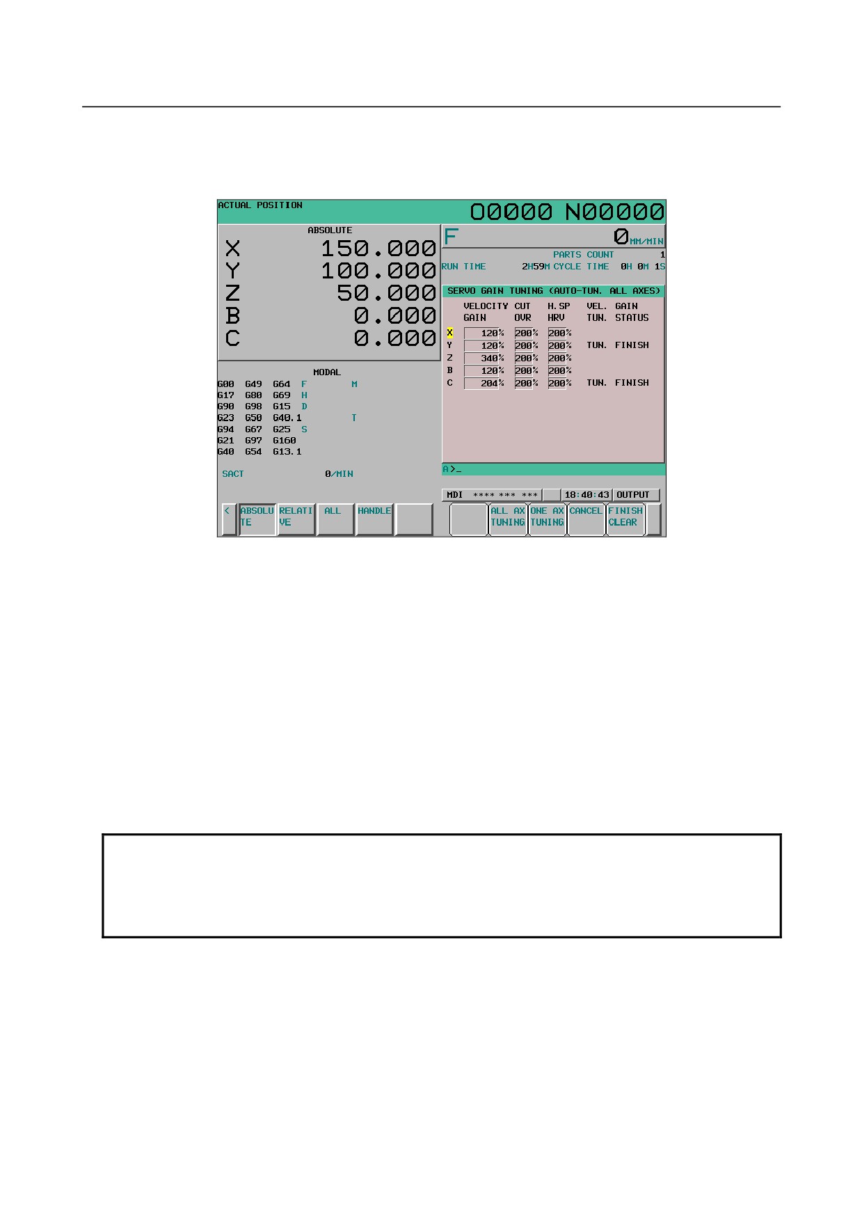
Fig. 12.4.10.7 (c) Servo gain tuning screen (all axis tuning) (10.4-inch)
- 634 -
B-64304EN/02
OPERATION 12.SETTING AND DISPLAYING DATA
- All axis tuning
When [ALL AX] is pressed on the automatic tuning screen, the following soft keys are displayed and
SERVO GAIN TUNING (AUTO-TUN. ALL AXES) is indicated on the title bar of the screen.
Fig. 12.4.10.7 (d) Automatic tuning screen (all axis tuning) (10.4-inch)
- All axis batch tuning
When no axis in a path is being subjected to automatic tuning, soft key [ALL AX TUNING] ([EXEC
ALL] for the 8.4-inch display unit) is displayed.
When soft key [ALL AX TUNING] is pressed during all axis tuning, all axes are subjected to automatic
tuning one by one, beginning with the first axis. However, the targets of automatic tuning are only the
axes for which automatic tuning is not completed. For example, in the conditions shown in the above
figure, automatic tuning starts with the X-axis and, when the X-axis is completed, proceeds to the Z-axis.
The Y-axis and C-axis are not subjected to automatic tuning.
The cursor keys are disabled during all axis batch tuning. Upon completion of automatic tuning of all
axes, the cursor returns to the first axis and the cursor keys are enabled.
If the screen is switched to another during all axis batch tuning, automatic tuning is canceled when
automatic tuning of the current axis is completed. To start automatic tuning again, display this screen
and press soft key [ALL AX TUNING].
NOTE
1 The axis for which TUN. FINISH or INIT. ERR is indicated under VEL. GAIN
TUN. STATUS is not subjected to automatic tuning.
2 If the screen is switched to another during all axis batch tuning, all axis batch
tuning is aborted.
- All axis step tuning
When no axis in a path is being subjected to automatic tuning, soft key [ONE AX TUNING] ([ONE EX]
for the 8.4-inch display unit) is displayed.
When soft key [ONE AX TUNING] is pressed, as in all axis batch tuning, the axes for which automatic
tuning is not completed are subjected to automatic tuning one by one, beginning with the first axis.
Each time an axis is subjected to automatic tuning, however, automatic tuning stops. At this time, the
cursor automatically moves to the next axis for which automatic tuning is not completed.
- 635 -