FANUC Series 0i-MODEL D, Series 0i Mate-MODEL D. OPERATOR'S MANUAL - page 20
12.SETTING AND DISPLAYING DATA OPERATION
B-64304EN/02
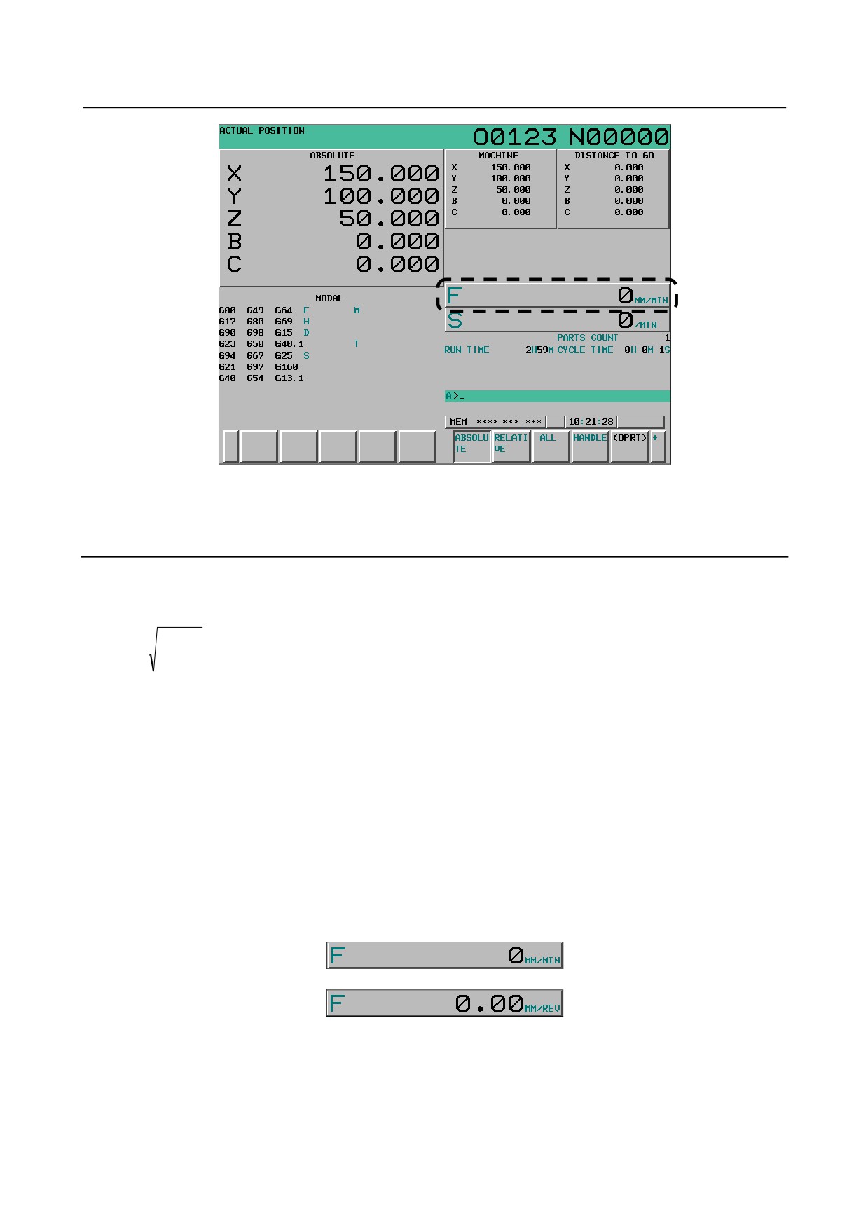
Fig. 12.1.5 (a) Current position (absolute) screen (10.4-inch)
The actual feedrate is displayed in units of millimeter/min or inch/min (depending on the specified least
input increment) under the display of the current position.
Explanation
-
Actual feedrate value
The actual rate is calculated by the following expression:
n
: Number of axes
2
Fact=
(fi)
fi
: Cutting feed rate in the tangential direction of each axis or rapid traverse rate
∑n
i=1
Fact
: Actual feedrate displayed
The display unit:
mm/min (metric input).
inch/min (Inch input, two digits below the decimal point are displayed.)
-
Actual feedrate display of feed per revolution
In the case of feed per revolution and thread cutting, the actual feedrate displayed is the feed per minute
rather than feed per revolution.
-
Actual feed per revolution
Switching between feed per minute display and actual feed per revolution display in the actual feedrate
table can be performed depending on bit 3 (GSC) of parameter No. 3107, bit 5 (FSS) of parameter No.
No.3191, the G code modal, and the operation state.
For feed per minute display, the unit is millimeter per minute. For actual feed per revolution, the unit is
millimeter per revolution.
↓
Input increment parameter INI (bit 2 of parameter No. 0) is used to switch between inch display and
millimeter display. The relationship between input increment parameter INI (bit 2 of parameter No. 0)
and unit display of actual feedrate and actual feed per revolution is shown below.
- 546 -
B-64304EN/02
OPERATION 12.SETTING AND DISPLAYING DATA
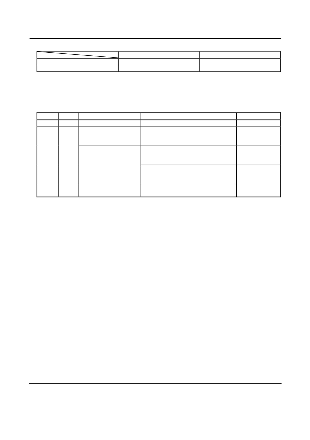
Table 12.1.5 (a) Unit display
Actual feedrate
Actual feed per revolution
Inch (INI=0)
MM/MIN
MM/R
Millimeter (INI=1)
INCH/MIN
INCH/R
-
Actual feedrate display switching condition
Actual feedrate display is switched as shown in the table below depending on the bit 3 (GSC) of
parameter No. 3107, bit 5 (FSS) of parameter No. No.3191, the G code modal, and the operation state.
Table 12.1.5 (b) Displayed information switching condition
GSC
FSS
Operation state
G code modal
Actual feedrate
0
-
-
-
Feed per minute
Manual feed
Rapid traverse
-
Feed per minute
Dry run
M series: G93, G94
0
T series: G98(G code system A)
Feed per minute
Other than Manual feed,
1
G93, G94(G code system B, C)
Rapid traverse, and Dry
M series: G95
run
Feed per
T series: G99(G code system A)
revolution
G95(G code system B, C)
Feed per
1
-
-
revolution
-
Actual feedrate display of rotary axis
In the case of movement of rotary axis, the speed is displayed in units of deg/min but is displayed on the
screen in units of input system at that time. For example, when the rotary axis moves at 50 deg/min, the
following is displayed: 50 mm/min (in metric input) or 0.50 inch/min (in inch input).
-
Actual feedrate display on the other screen
For the 8.4-inch display unit, the actual feedrate is displayed on the program check screen.
It is also displayed on the graphic screen.
-
Displaying the number of decimal places
For actual feedrate display, the number of decimal places is indicated as described below depending on
the setting of parameter No. 3135 and the input unit.
Setting 0: Millimeter input With no decimal point
1: Millimeter input One digit to the right of the decimal point
2: Millimeter input Two digits to the right of the decimal point
3: Millimeter input Three digits to the right of the decimal point
For inch input, the number of decimal places is the setting plus 2.
For feed per revolution display, the number of decimal places is described below.
When the input unit is millimeter, the number of displayed decimal places is two.
When the input unit is inch, the number of displayed decimal places is three.
* The number of decimal places is fixed, so it cannot be changed by a parameter or the like.
12.1.6 Display of Run Time and Parts Count
The run time, cycle time, and the number of machined parts are displayed on the current position display
screens.
- 547 -
12.SETTING AND DISPLAYING DATA OPERATION
B-64304EN/02
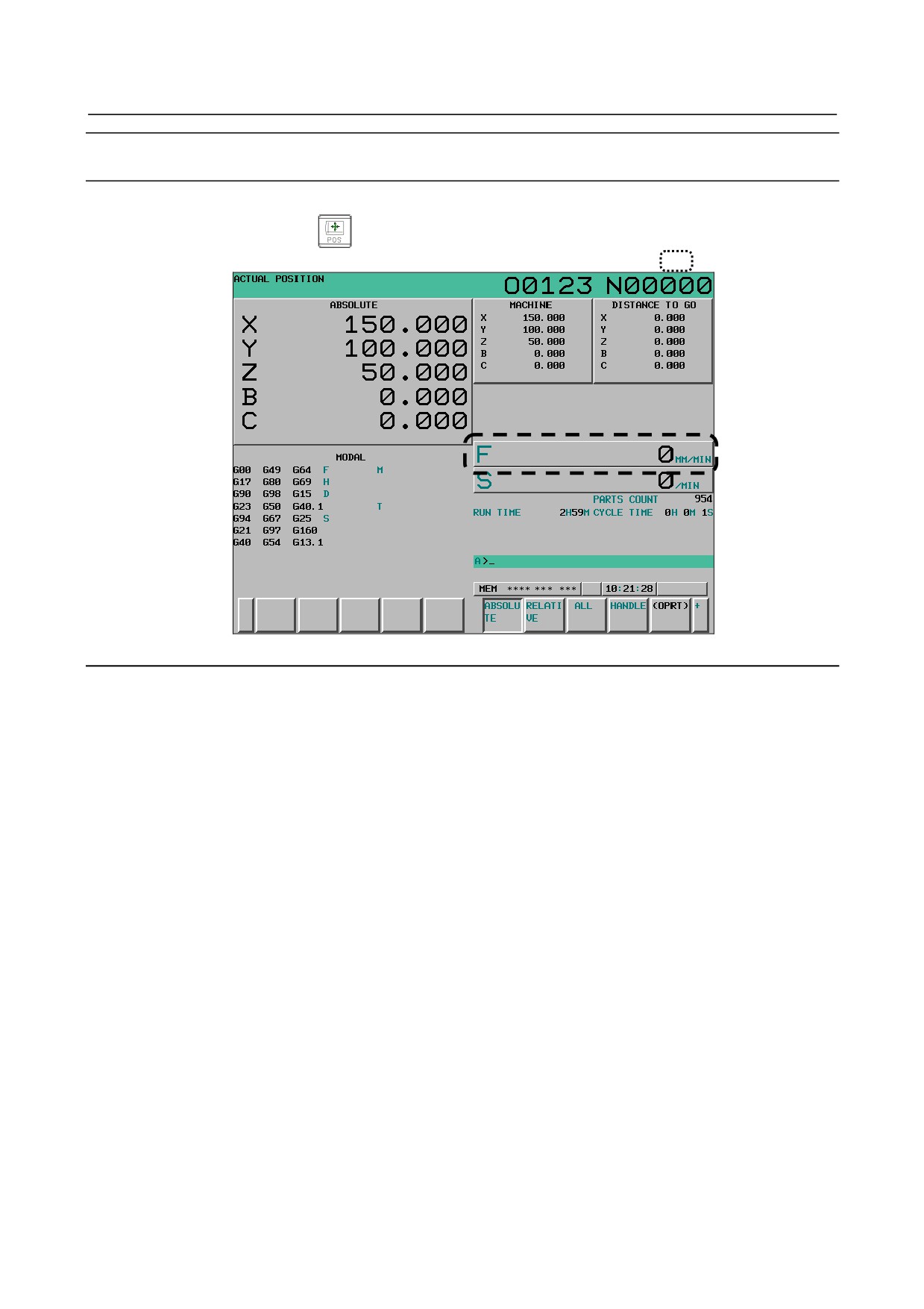
Procedure for displaying run time and parts count on the current position display
screen
Procedure
1
Press the function key
to display a current position display screen. "PARTS COUNT",
"RUN TIME", and "CYCLE TIME" are displayed in the area enclosed by
Fig. 12.1.6 (a) Current position (relative) screen (10.4-inch)
Explanation
-
PART COUNT
Indicates the number of machined parts. The number is incremented each time M02, M30, or an M code
specified by parameter No. 6710 is executed.
-
Incrementing the number of machined parts
Bit
0 (PCM) of parameter No. 6700 is used to specify whether the number of machined parts is
incremented each time M02, M30, or an M code specified by parameter No. 6710 is executed, or only
each time an M code specified by parameter No. 6710 is executed.
-
RUN TIME
Indicates the total run time during automatic operation, excluding the stop and feed hold time.
-
CYCLE TIME
Indicates the run time of one automatic operation, excluding the stop and feed hold time. This is
automatically preset to 0 when a cycle start is performed at reset state. It is preset to 0 even when power is
removed.
-
Display on the other screen
Details of the run time and the number of machined parts are displayed on the setting screen. See
III-12.3.3.
-
Parameter setting
The number of machined parts and run time cannot be set on current position display screens.
The number of machined parts and run time cannot be set on current position display screens. They can
be set by parameters Nos. 6711, 6751, and 6752 or on the setting screen.
- 548 -
B-64304EN/02
OPERATION 12.SETTING AND DISPLAYING DATA
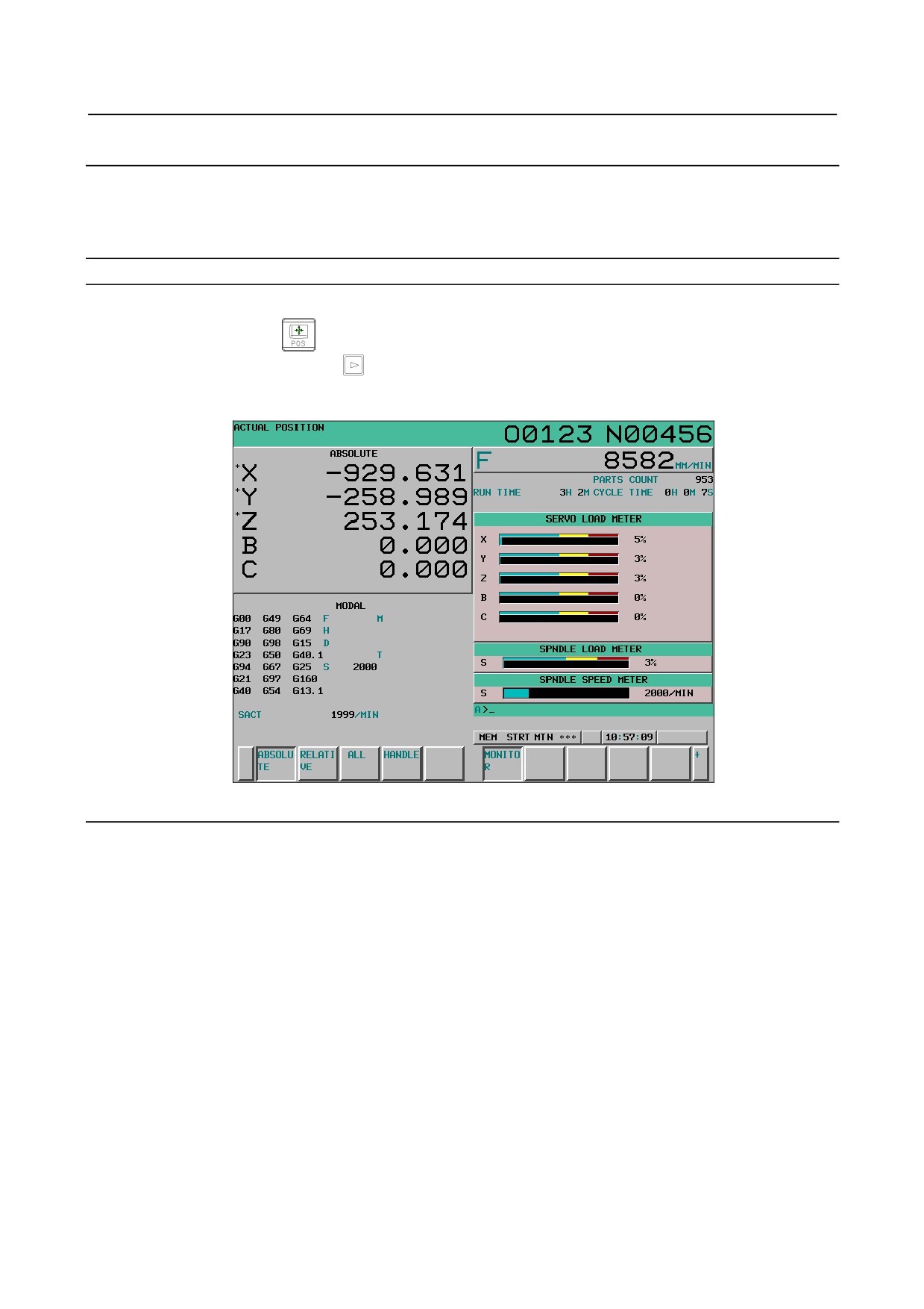
12.1.7 Operating Monitor Display
The load meter for a servo axis can be displayed. Also, the load meter and speed meter for a serial spindle
can be displayed.
To enable this function, bit 5 (OPM) of parameter No. 3111 must be set to 1.
Procedure for displaying the operating monitor
Procedure
1
Press function key
2
Press continuous menu key
3
Press soft key [MONITOR].
Fig. 12.1.7 (a) Operating monitor (10.4-inch)
Explanation
-
Display of the servo axes
Servo axis load meters as many as the maximum number of controlled axes of the path can be displayed.
For the 10.4-inch display unit, up to five axes can be concurrently displayed on one screen. If soft key
[MONITOR] is pressed, the load meters of the sixth and subsequent axes are displayed.
For the 8.4-inch display unit, up to four axes can be concurrently displayed on one screen. If soft key
[MONITOR] is pressed, the load meters of the fifth and subsequent axes are displayed.
To display up to five axes concurrently on one screen of the 8.4-inch display unit as in the 10.4-inch
display unit, set bit 4 (9DE) of parameter No. 11350 to 1.
-
Display of the spindle axes
Both a load meter and spindle meter can be displayed for the first spindle when a serial spindle is used.
-
Unit of graph
The bar graph for the load meter shows load up to 200% (only a value is displayed for load exceeding
200%).
The bar graph for the speedometer shows the ratio of the current spindle speed to the maximum spindle
speed (100%).
- 549 -
12.SETTING AND DISPLAYING DATA OPERATION
B-64304EN/02
-
Load meter
The reading on the load meter depends on servo parameter No. 2086 and spindle parameter No. 4127.
-
Speedometer
Although the speedometer normally indicates the speed of the spindle motor, it can also be used to indicate
the speed of the spindle by setting bit 6 (OPS) of parameter No. 3111 to 1.
The spindle speed to be displayed during operation monitoring is calculated from the speed of the spindle
motor (see the formula below).
The spindle speed can therefore be displayed, during operation monitoring, even when no position coder is
used.
To display the correct spindle speed, however, the maximum spindle speed for each gear (spindle speed at
each gear ratio when the spindle motor rotates at the maximum speed) must be set in parameters No. 3741
to No.3744.
Input of the clutch/gear signal for the first spindle of the serial spindle is used to determine the gear
currently selected, so input of signals CTH1A and CTH2A must be controlled according to the gear
selection with reference to the table below.
(Formula for calculating the spindle speed to be displayed)
Spindle speed displayed
Speed of spindle motor Maximum spindle speed
=
×with the gear being used
during operation monitoring
Maximum speed of
spindle motor
The following table lists the correspondence between clutch and gear selection signals CTH1A and
CTH2A, used to determine the gear being used, and parameters:
CTH1A
CTH2A
Parameter
Serial spindle specification
0
0
=No.3741 (Maximum spindle speed with gear 1)
HIGH
0
1
=No.3742 (Maximum spindle speed with gear 2)
MEDIUM HIGH
1
0
=No.3743 (Maximum spindle speed with gear 3)
MEDIUM LOW
1
1
=No.3744 (Maximum spindle speed with gear 4)
LOW
The speed of the spindle motor and spindle can be displayed, during operation monitoring, only for the
first serial spindle and the spindle switching axis for the first serial spindle. It cannot be displayed for the
second spindle.
-
Color of graph
If the value of a load meter exceeds 100%, the bar graph turns yellow.
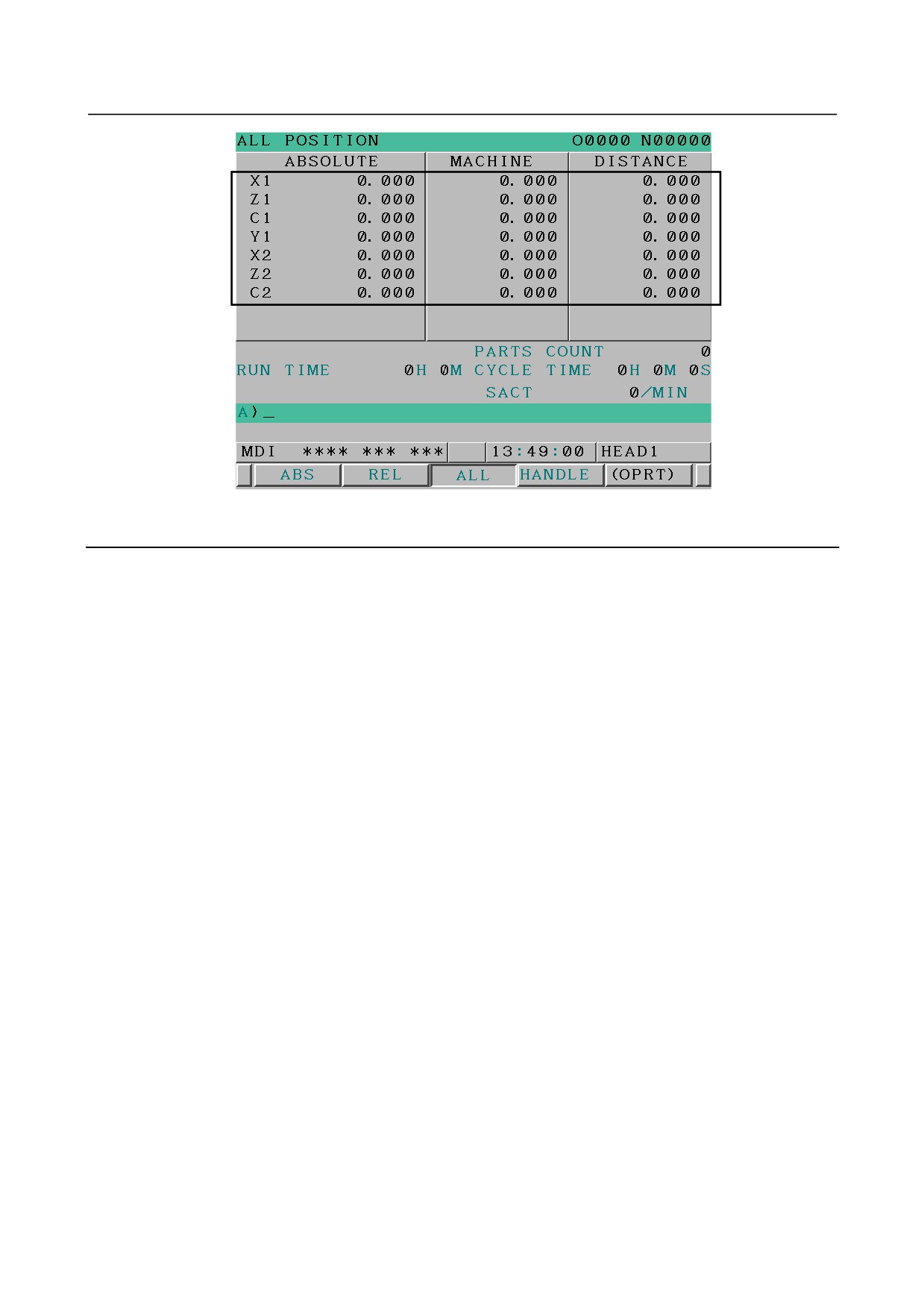
12.1.8 Display of Axes in 2-path System Simultaneously
T
In the current position display screen of 8.4-inch display unit, the axes information for 2-path system can
be displayed without switching the system.
The display of axes in 2-path system simultaneously becomes effective in the following screens.
• The total position display screen
• The manual handle interruption amount display screen
Procedure for displaying the total position display screen and the manual handle
interruption amount display screen
Procedure
1
Press function key
2
Press chapter selection key [ALL] to display the relative total position display screen.
Press chapter selection key [HNDL] to display the manual handle interruption amount display
screen.
- 550 -
B-64304EN/02
OPERATION 12.SETTING AND DISPLAYING DATA
Fig. 12.1.8 (a) The display of axes in 2-path system simultaneously
(in the total position display screen)
Explanation
-
Condition to display
The display of axes in 2-path system simultaneously becomes effective when all conditions of 1-5 the
following is full.
1
2-path system (TT system) is used.
2
8.4-inch display unit is used.
3
The simultaneous display of 2-path is enabled (bit 2 (DOP) of parameter No. 3193 = 0).
4
The number of axes that can be displayed on one screen of the 8.4-inch display unit is up to 5 (bit 4
(9DE) of parameter No. 11350 = 1).
5
The current position display screen displays two paths regardless of path selection signal
HEAD<G0063.0> (bit 1 (DIP) of parameter No.3103 = 0).
-
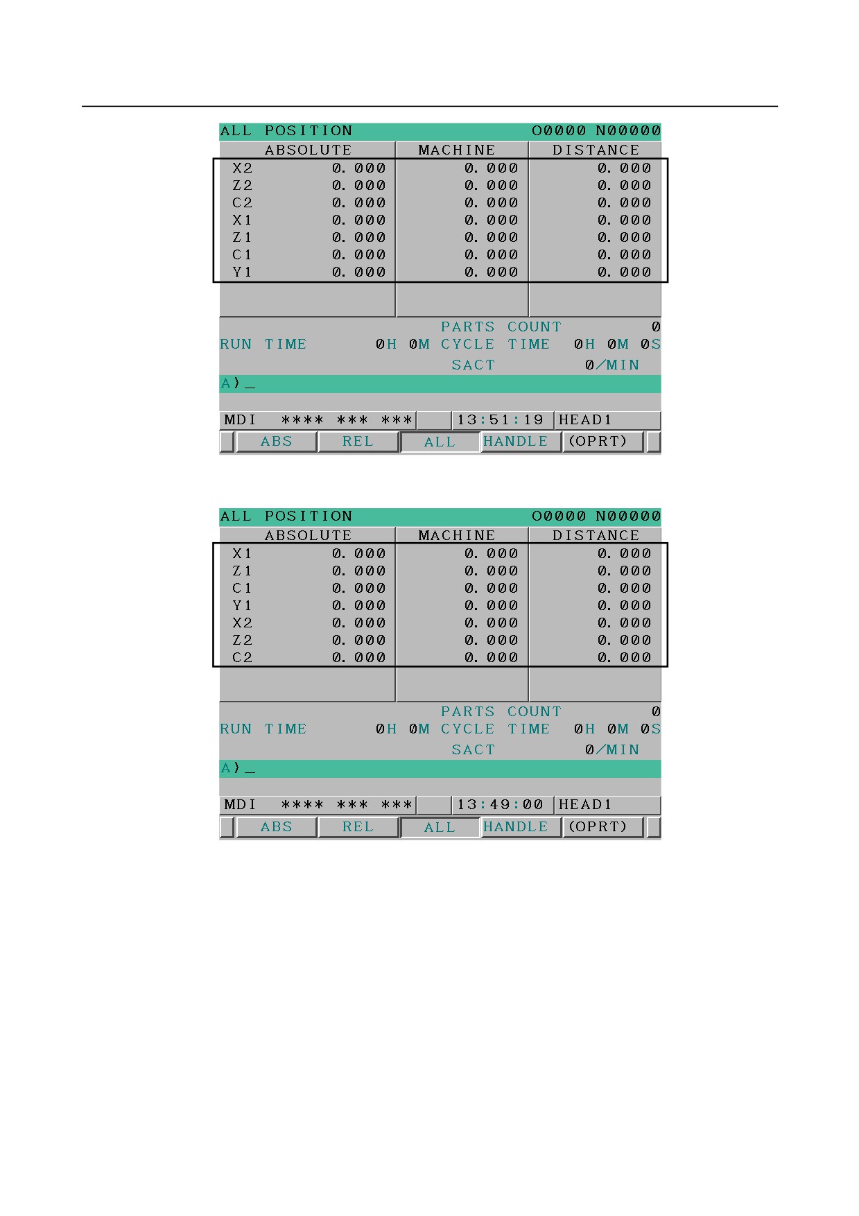
The order of displaying each path
In the current position display screen, if the parameter which decides display order of each path ( bit 7
(SBA) of parameter No.3101) is set to 1, the axes information in the 2nd path can be displayed ahead.
When 0 is set in it, the axes information in the 1st path is displayed ahead.
- 551 -
12.SETTING AND DISPLAYING DATA OPERATION
B-64304EN/02
Fig. 12.1.8 (b) The axes information is displayed in order in the
2nd -> 1st path (in the total position display screen)
Fig. 12.1.8 (c) The axes information is displayed in order in the
1st -> 2nd path (in the total position display screen)
- 552 -
B-64304EN/02
OPERATION 12.SETTING AND DISPLAYING DATA
-
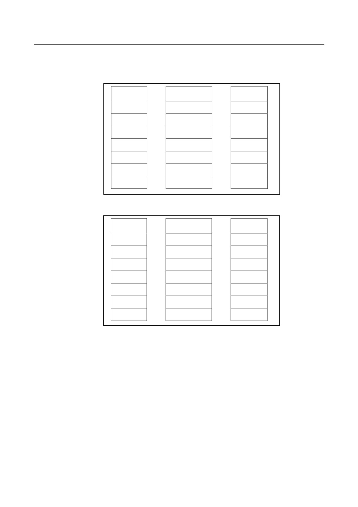
The order of displaying each axis
The order of the axes displayed in the current position display screen can be specified (parameter
(No.3130)). The order of the axes which can be specified is limited in order in each path. The order of the
axes cannot be specified across the axis in the other path.
Before the
Parameter
After the
replacement
No.3130
replacement
X1
4
Y1
Z1
3
C1
→
→
C1
2
Z1
Y1
1
X1
X2
3
C2
Z2
2
Z2
C2
1
X2
Fig. 12.1.8 (d) Specification of the order of displaying each axis
(specification with axes in each path)
Before the
Parameter
After the
replacement
No.3130
replacement
X1
7
(Blank)
Z1
6
(Blank)
→
→
C1
5
(Blank)
Y1
4
Y1
X2
3
C2
Z2
2
Z2
C2
1
X2
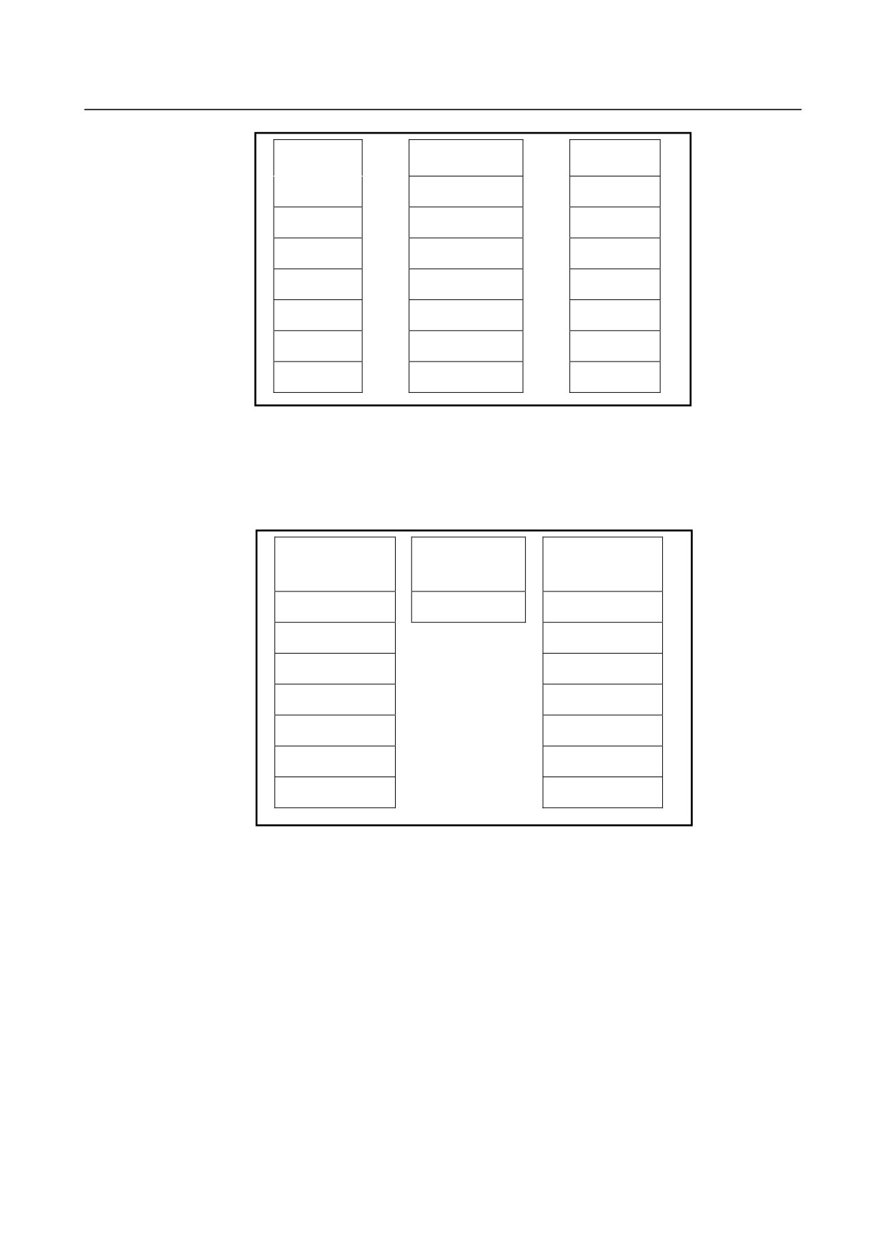
Fig. 12.1.8 (e) Specification of the order of displaying each axis
(specification with axes across the other path)
-
Non-display of the axis
When the order of displaying the axes is specified, the axis for which 0 is specified in the order of the
display becomes non-display.
- 553 -
12.SETTING AND DISPLAYING DATA OPERATION
B-64304EN/02
Before the
Parameter
After the
replacement
No.3130
replacement
X1
1
X1
Z1
2
Z1
→
→
C1
0
(Blank)
Y1
4
Y1
X2
1
X2
Z2
2
Z2
C2
0
(Blank)
Fig. 12.1.8 (f) Specification of non-display of the axis
-
Display of axis with top-alignment
To the area where the current position display becomes blank by being set as non-display, the current
position is displayed with top-alignment by another axis for which the current position is displayed by
setting 1 to bit 0 (TAD) of parameter No.13102.
Before displaying
Parameter
After displaying
the axis with
No.13102#0
the axis with
top-alignment
top-alignment
X1
0 -> 1
X1
Z1
Z1
(Blank)
Y1
Y1
X2
X2
Z2
Z2
(Blank)
(Blank)
(Blank)
Fig. 12.1.8 (g) Specification of display of axis with top-alignment
- 554 -
B-64304EN/02
OPERATION 12.SETTING AND DISPLAYING DATA
12.2 SCREENS DISPLAYED BY FUNCTION KEY
Section
12.2, "SCREENS DISPLAYED BY FUNCTION KEY
", consists of the following
subsections:
12.2.1 Program Contents Display
555
12.2.2 Editing a Program
556
12.2.3 Program Screen for MDI Operation
558
12.2.4 Program List Screen
558
12.2.5 Next Block Display Screen
559
12.2.6 Program Check Screen
560
12.2.7 Current Block Display Screen (Only for the 8.4-Inch Display Unit)
563
12.2.8 Graphical Conversational Programming Screen
564
12.2.9 Background Editing
566
This section describes the screens displayed by pressing function key
. There are the program
editing screen, the program list screen, and the screen for displaying the status of the command specified
by the program currently being executed.
1.
Program screen
2.
Program list screen
3.
Next block display screen
4.
Program check screen (8.4-inch LCD)
On the program screen, you edit the program that is currently selected, and display the block that is
currently executed during program operation. In MDI mode, you also edit an MDI operation program,
and display the block that is currently executed.
12.2.1 Program Contents Display
Displays the program currently being executed in MEM mode.
Displaying the program being executed
Procedure
1
Press function key
to display the program screen.
2
Press chapter selection soft key [PROGRAM].
The cursor is positioned at the block currently being executed.
- 555 -
12.SETTING AND DISPLAYING DATA OPERATION
B-64304EN/02
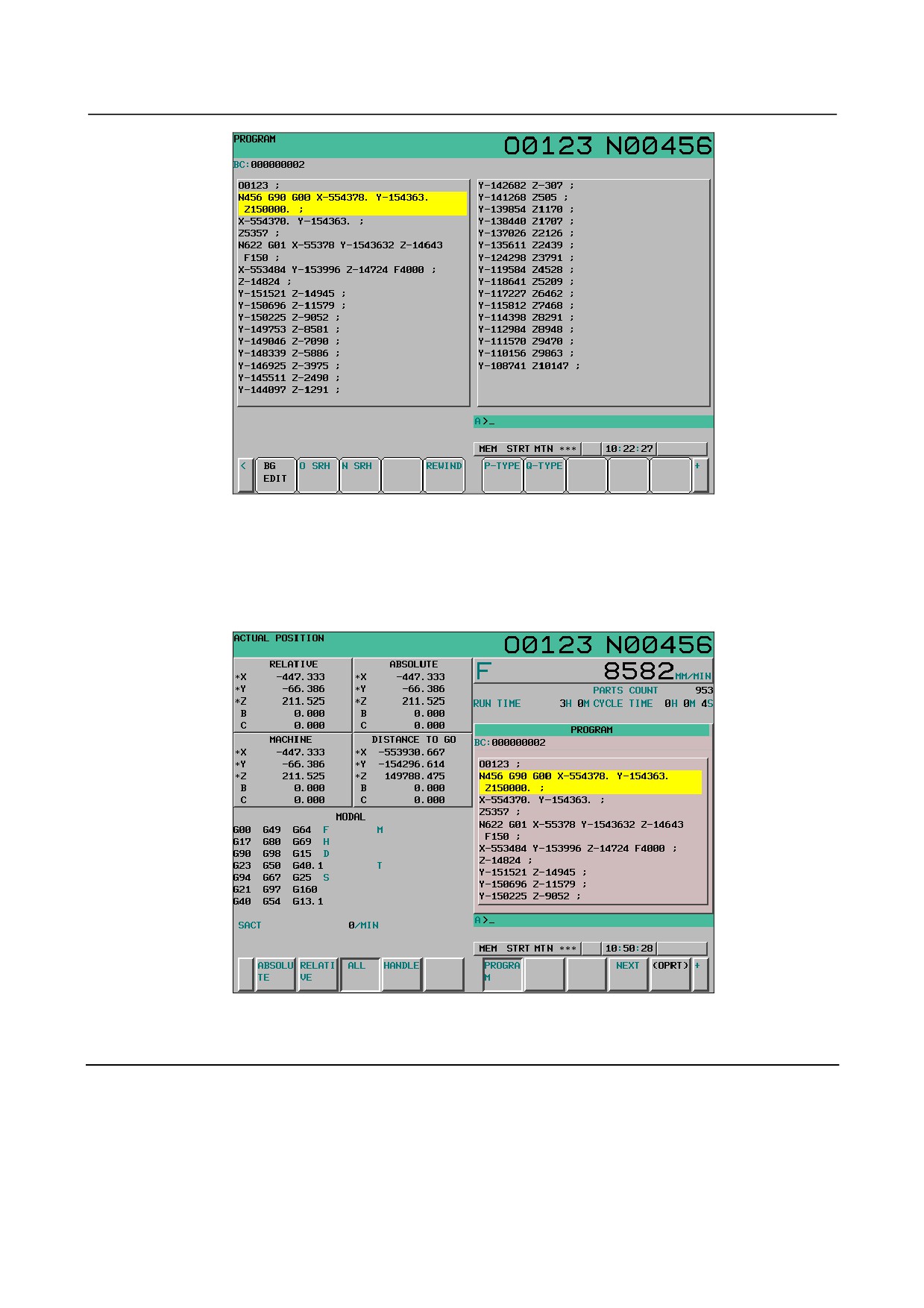
Fig. 12.2.1 (a) Screen for displaying the program being executed (full screen display) (10.4-inch)
For the 10.4-inch display unit, if soft key [PROGRAM] is pressed again to switch screen display to full
screen display or small screen display.
In small screen display, position display and modal display are allowed at the same time.
In full screen display, much information about a program can be displayed at a time.
Fig.12.2.1 (b) Screen for displaying the program being executed (small screen display) (10.4-inch)
12.2.2 Editing a Program
A program can be edited in the EDIT mode.
A program can be edited on a word-by-word basis.
For program creation and editing operation, see Chapter III-9, “CREATING PROGRAMS” and Chapter
III-10, “EDITING PROGRAMS”.
- 556 -
B-64304EN/02
OPERATION 12.SETTING AND DISPLAYING DATA
Displaying the program editing screen
Procedure
1
Press function key
to display the program screen.
2
Press chapter selection soft key [PROGRAM].
Editing operations such as text insertion, modification, and deletion, and cursor movements are performed
on a word-by-word basis.
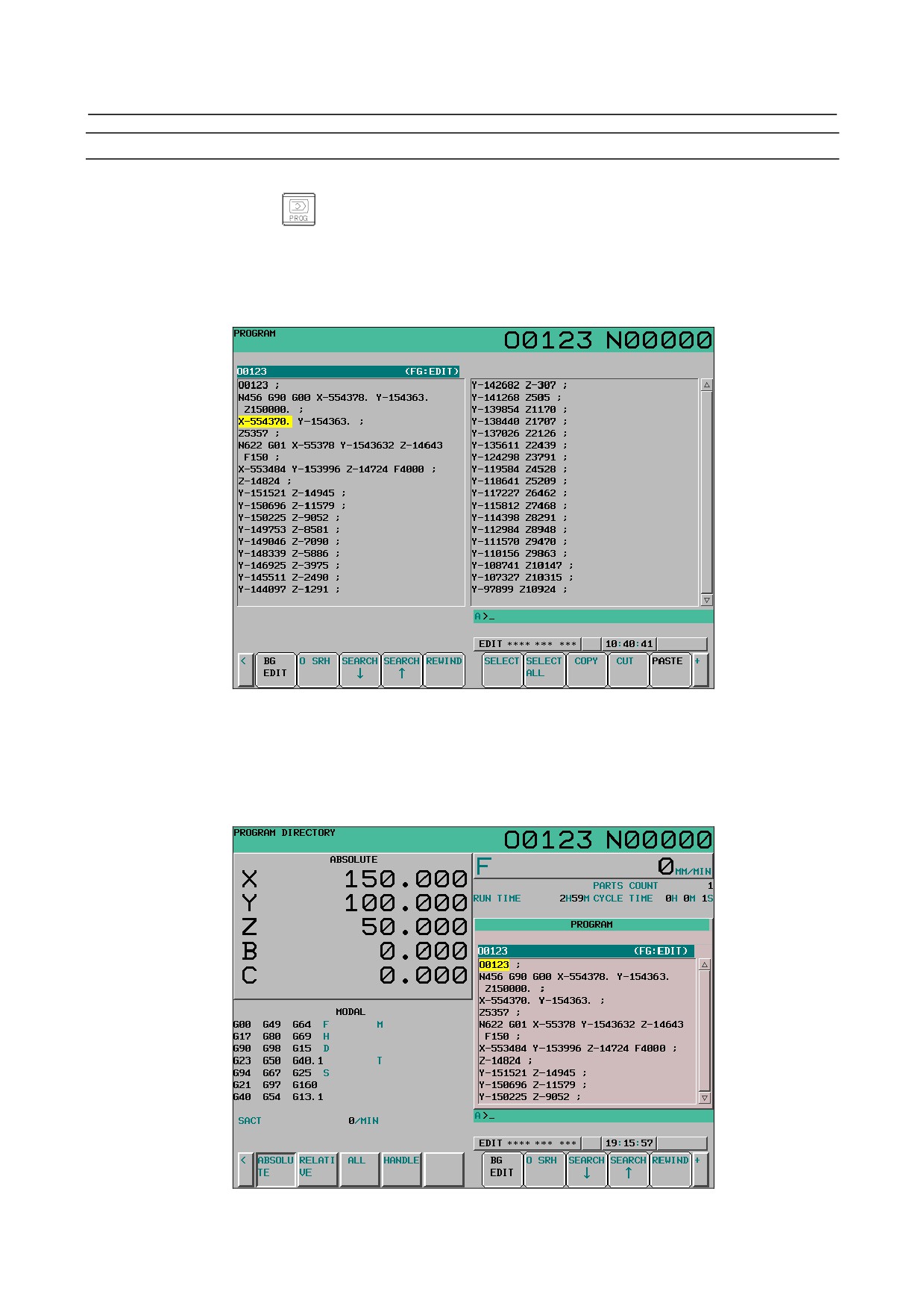
Fig. 12.2.2 (a) Program editing screen (quarter screen display) (10.4-inch)
For the 10.4-inch display unit, if soft key [PROGRAM] is pressed again during editing to switch screen
display to full screen display or small screen display.
In small screen display, position display and modal display are allowed at the same time.
In full screen display, much information about a program can be displayed at a time.
Fig. 12.2.2 (b) Program editing screen (small screen display) (10.4-inch)
- 557 -
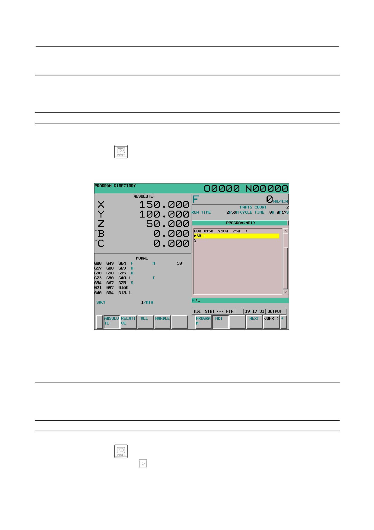
12.SETTING AND DISPLAYING DATA OPERATION
B-64304EN/02
12.2.3 Program Screen for MDI Operation
During MDI operation or editing of an MDI operation program in the MDI mode, the program currently
being executed mode is displayed.
For MDI operation, see Section III-4.2, “MDI Operation”.
Procedure for displaying the program screen for MDI operation
Procedure
1
Enter the MDI mode.
2
Press function key
3
Press chapter selection soft key [MDI].
The program input from the MDI is displayed.
Fig. 12.2.3 (a) MDI operation program screen (10.4-inch)
In case of the 8.4-inch display unit, when bit 7 (MDL) of parameter No.3107 is set 1, the modal
information can be displayed in the screen.
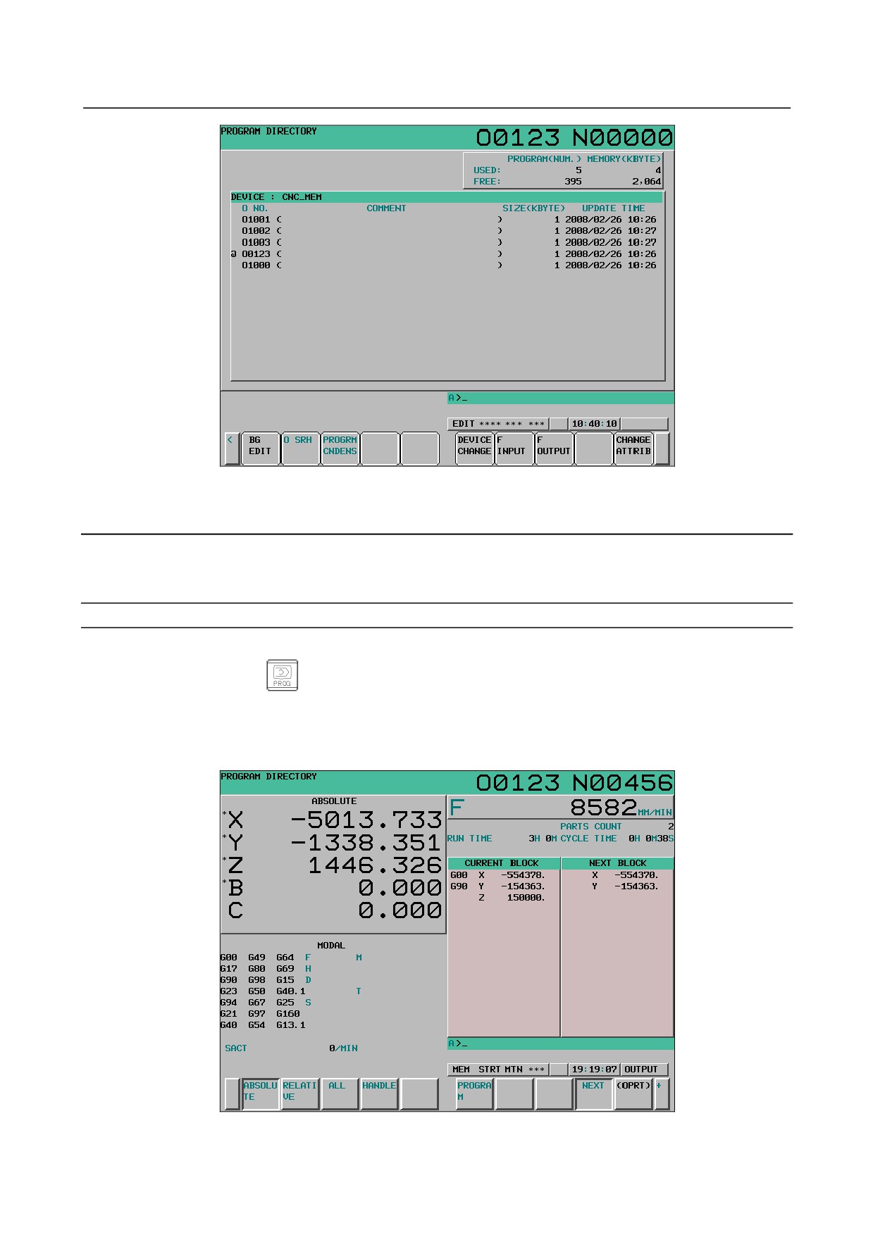
12.2.4 Program List Screen
A list of programs registered in the program memory is displayed.
The program list screen can be displayed in any mode.
For the program list screen, see Chapter III-11, “PROGRAM MANAGEMENT”.
Displaying the program list screen
Procedure
1
Press function key
2
Press continuous menu key
2
Press chapter selection soft key [LIST].
- 558 -
B-64304EN/02
OPERATION 12.SETTING AND DISPLAYING DATA
Fig. 12.2.4 (a) Program list screen (10.4-inch)
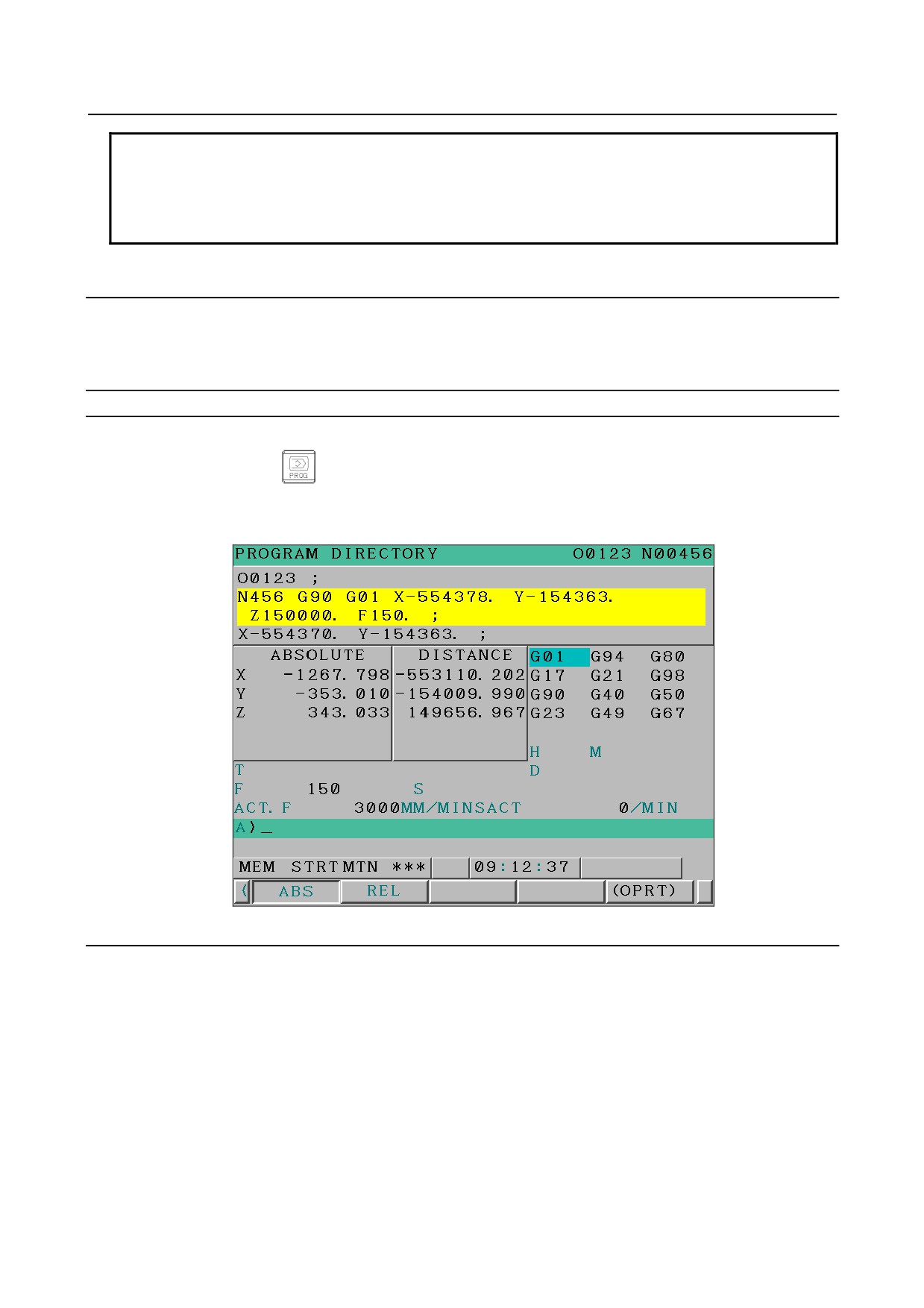
12.2.5 Next Block Display Screen
The block currently being executed and the block to be executed next are displayed in the MEM mode
and MDI model.
Procedure for displaying the next block display screen
Procedure
1
Press function key
2
Press chapter selection soft key [NEXT].
The G codes, addresses, command values specified in the block currently being executed and the
next block are displayed.
Fig. 12.2.5 (a) Next block display screen (10.4-inch)
- 559 -
12.SETTING AND DISPLAYING DATA OPERATION
B-64304EN/02
NOTE
1 If a reset is made during execution of a program, the display of the current block
and next block is cleared.
2 When the feed hold state (HOLD) is caused between the block and the block
during the program execution, the next block display is cleared.
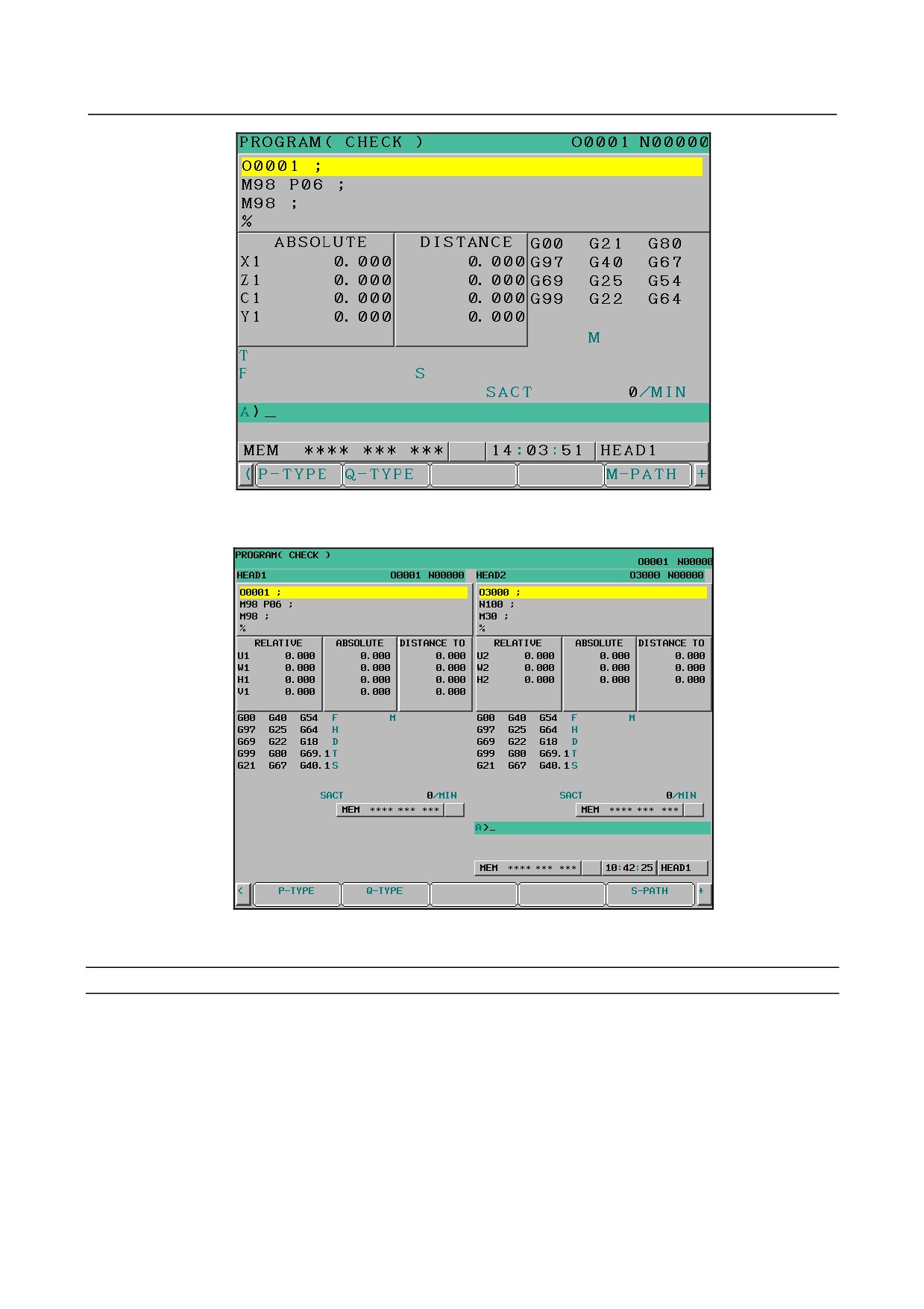
12.2.6 Program Check Screen
The program currently being executed, the current position and modal information are displayed in the
MEM mode. This screen is displayed when the simultaneous display of 2-path is enabled in the 2-path
system.
Procedure for displaying the program check screen
Procedure
1
Press function key
2
Press chapter selection soft key [CHECK].
The program currently being executed, current position of the tool, and modal data are displayed.
Fig. 12.2.6 (a) Program check screen (8.4-inch)
Explanation
-
Program display
Up to four blocks from the beginning of the block being executed in the program currently being
executed are displayed.
The block being executed is displayed in reverse video.
-
Current position display
Chapter selection soft key [RELATIVE] or [ABSOLUTE] can be pressed to switch between relative
coordinate system display and workpiece coordinate system display.
-
Modal G codes
Up to 12 modal G codes are displayed.
- 560 -
B-64304EN/02
OPERATION 12.SETTING AND DISPLAYING DATA
-
Display of the actual speed and SACT
The actual speed is displayed with mm/min or inch/min according to unit of input.
The actual spindle speed (SACT) is displayed.
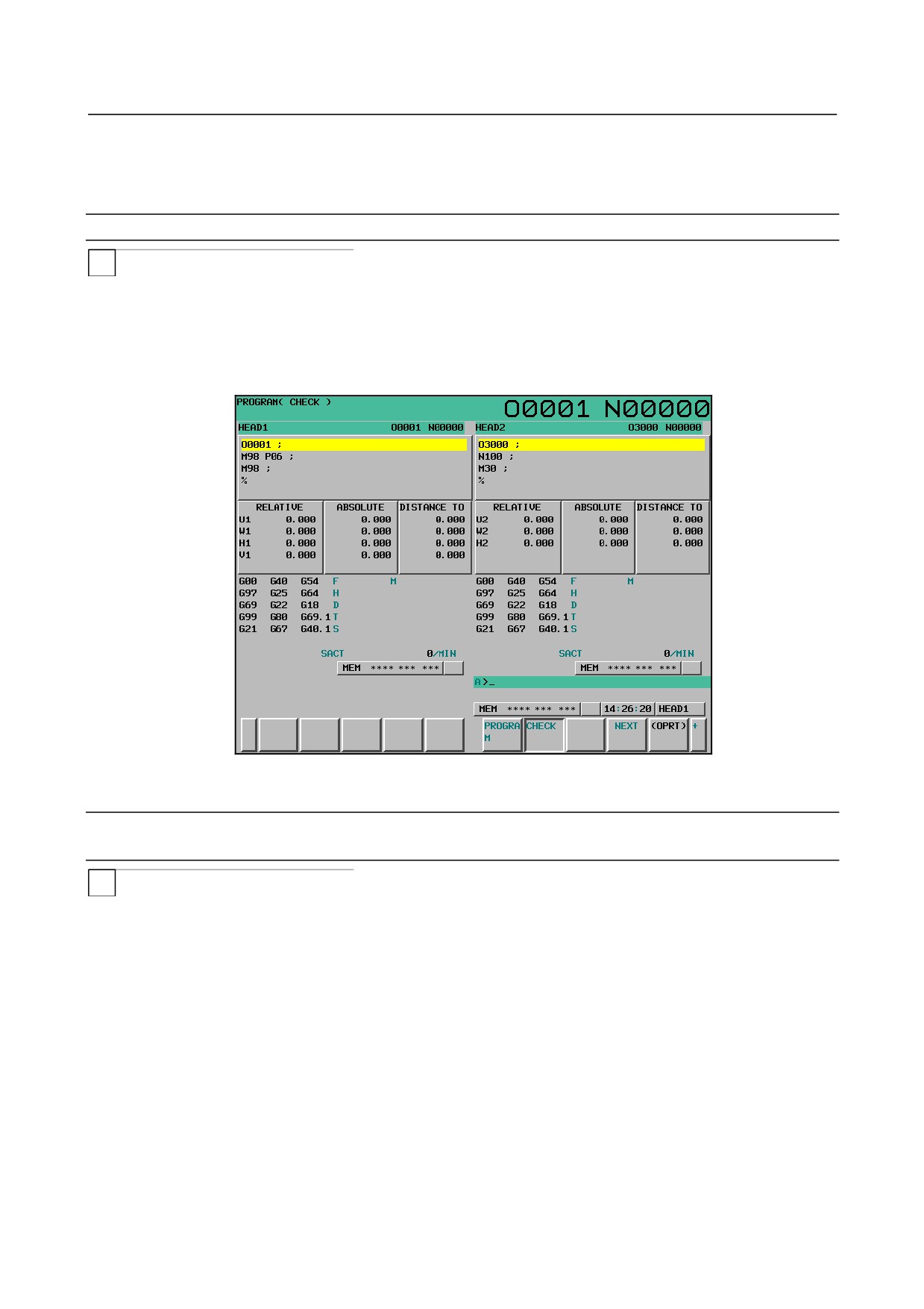
The simultaneous display of 2-path (for the 10.4-inch display unit)
T
The simultaneous display of 2-path can be done at the TT (2-path) system.
In the 10.4-inch display unit, chapter selection soft key [CHECK] is displayed by making this function
effective.
It is necessary to set 1 to bit 0 (DHD) of parameter No.3106 and 0 to bit 2 (DOP) of parameter No.3193
to make this function effective.
Fig. 12.2.6 (b) The simultaneous display of 2-path
at program check screen (for the 10.4-inch display unit)
Switch of the display of 1-path and the simultaneous display of 2-path (for the
8.4-inch display unit)
T
In the 8.4-inch display unit, the display can be switched to the display of 1-path and the simultaneous
display of 2-path by pressing operation selection soft key.
It is necessary to set 0 to bit 0 (DHD) of parameter No.3106 and 0 to bit 2 (DOP) of parameter No.3193
to make this function effective.
When the power is turned on, the display of 1-path has been selected.
Procedure
1
Press operation selection soft key [M-PATH].
2
The program check screen changes from the display of 1-path to the simultaneous display of 2-path.
The display of the soft key changes from [M-PATH] to [S-PATH].
3
Press operation selection soft key [S-PATH].
4
The program check screen changes from the simultaneous display of 2-path to the display of 1-path.
The display of the soft key changes from [S-PATH] to [M-PATH].
- 561 -
12.SETTING AND DISPLAYING DATA OPERATION
B-64304EN/02
Fig. 12.2.6 (c) The display of 1-path
at program check screen (for the 8.4-inch display unit)
Fig. 12.2.6 (d) The simultaneous display of 2-path
at program check screen (for the 8.4-inch display unit)
Load meter and speedometer display (for the 8.4-inch display unit)
In the 8.4-inch display unit, the display can be switched to the display of the amount of the movement to
be made and modal information and the display of spindle load meter and spindle speedometer by
pressing operation selection soft key.
It is necessary to set 1 to bit 0 (SMS) of parameter No.3117 to make this function effective.
Procedure
1
Press operation selection soft key [MONI].
2
The display of the amount of the movement to be made and modal information changes to the
display of spindle load meter and spindle speedometer on the program check screen.
The display of the soft key changes from [MONI] to [D.GO].
3
Press operation selection soft key [D.GO].
- 562 -

B-64304EN/02
OPERATION 12.SETTING AND DISPLAYING DATA
4
The display of spindle load meter and spindle speedometer changes to the display of the amount of
the movement to be made and modal information on the program check screen.
The display of the soft key changes from [D.GO] to [MONI].
Explanation
-
Target spindle to display
Only load meter and speedometer of the first serial spindle can be displayed.
-
Load meter
The display of load meter depends on setting the spindle parameter No.4127.
The graph of load meter is displayed up to 200%.
-
Speedometer
Speedometer displays the spindle motor speed, but it is possible to change to the display of spindle speed
by setting as bit 6 (OPS) of parameter No.3111 = 1.
Displayed spindle speed is calculated by using the spindle motor speed. (Refer to the expression below)
Therefore, the spindle speed can be displayed even if there is no position coder.
However, It is necessary to set parameter No.3741-3744 (the maximum spindle speed at each gear)
correctly to display correct spindle speed.
Moreover, the gear under the selection is judged by using clutch/gear signals to the first serial spindle.
Expression for spindle speed display
Spindle motor speed
The maximum spindle speed at gear
Displayed spindle speed=
×
Maximum spindle motor speed
under the selection
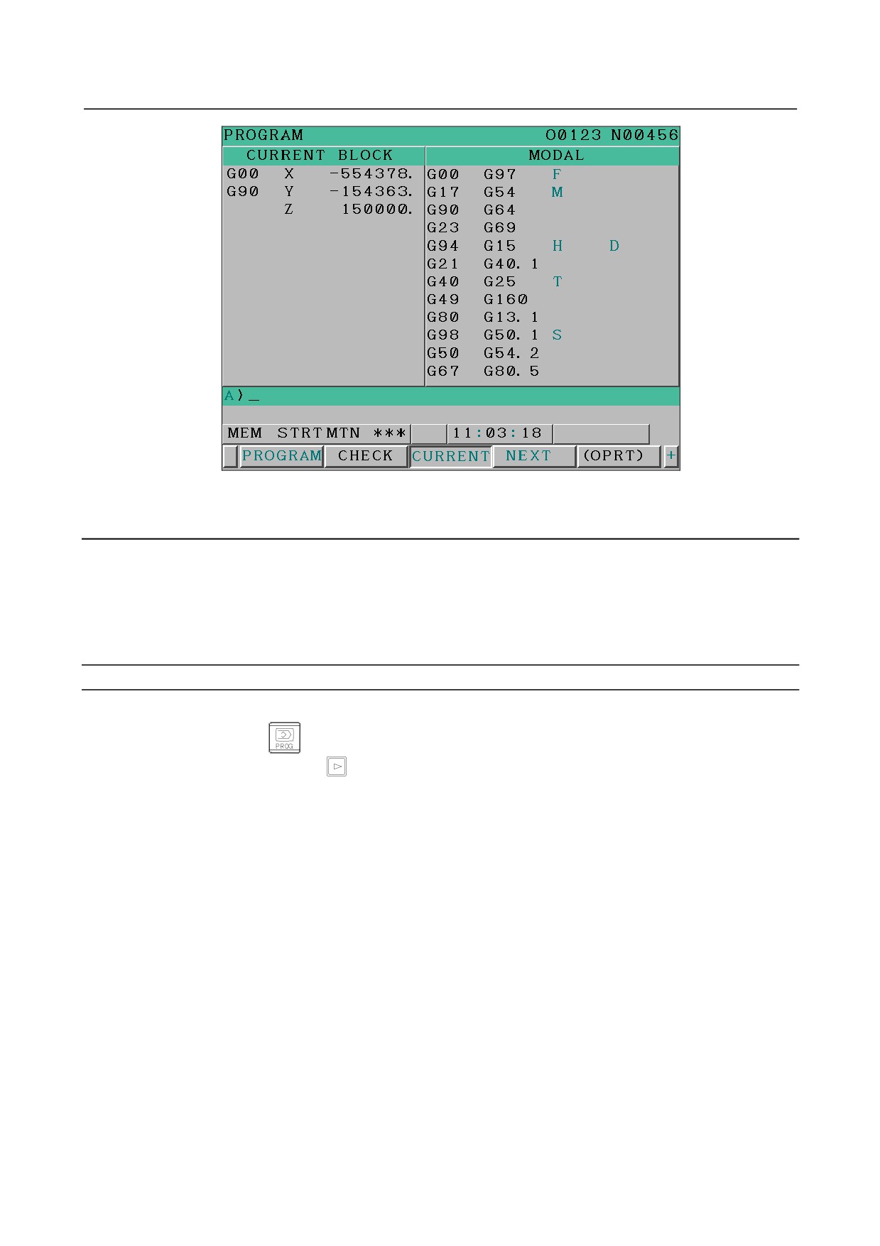
12.2.7 Current Block Display Screen (Only for the 8.4-Inch Display
Unit)
The block currently being executed and modal specification value are displayed in the MEM mode and
MDI mode.
Displaying the current block screen
Procedure
1
Press function key
2
Press chapter selection soft key [CURRENT].
The modal specification values, specification values, addresses, and G codes specified in the block
currently being executed are displayed.
- 563 -
12.SETTING AND DISPLAYING DATA OPERATION
B-64304EN/02
Fig. 12.2.7 (a) Current block screen (8.4-inch)
12.2.8 Graphical Conversational Programming Screen
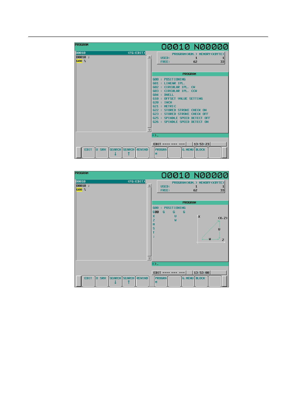
The G code menu and details on G codes are displayed in the EDIT mode.
A program can be created one block at a time while seeing the G code menu on the screen and the G code
detail screen.
For details on the conversational programming with the graphic function, see Chapter III-11,
"PROGRAM CREATION".
Displaying the graphic conversational programming screen
Procedure
1
Press function key
2
Press continuous menu key
3
Press chapter selection soft key [C.A.P].
- 564 -
B-64304EN/02
OPERATION 12.SETTING AND DISPLAYING DATA
Fig. 12.2.8 (a) Graphical conversational programming screen (G code menu screen) (10.4-inch)
Fig. 12.2.8 (b) Graphical conversational programming screen (G code detail screen) (10.4-inch)
The G code menu screen and G code detail screen are present on the graphical conversational
programming screen.
To display the G code detail screen, press soft key [BLOCK]. To display the G code menu screen, press
soft key [G. MENU].
G code menu screen
On the G code menu screen, select a G code to be specified from a list of G codes displayed.
G code detail screen
On the G code detail screen, enter the necessary values since the specification form for each G code is
displayed.
- 565 -
12.SETTING AND DISPLAYING DATA OPERATION
B-64304EN/02
12.2.9 Background Editing
Editing of a program other than the main program is called background editing. In background editing,
a program can be edited during execution of another program and the same editing operations as normal
editing (foreground editing) can be performed. There are the editing mode and reference mode in
background editing. A program can be edited in the editing mode, but a program cannot be edited in the
reference mode. In the reference mode, a program being operated can be referenced.
Background editing can be performed in any mode.
Function
-
Editable programs
The editable programs for each device are shown below.
Editable programs for each device
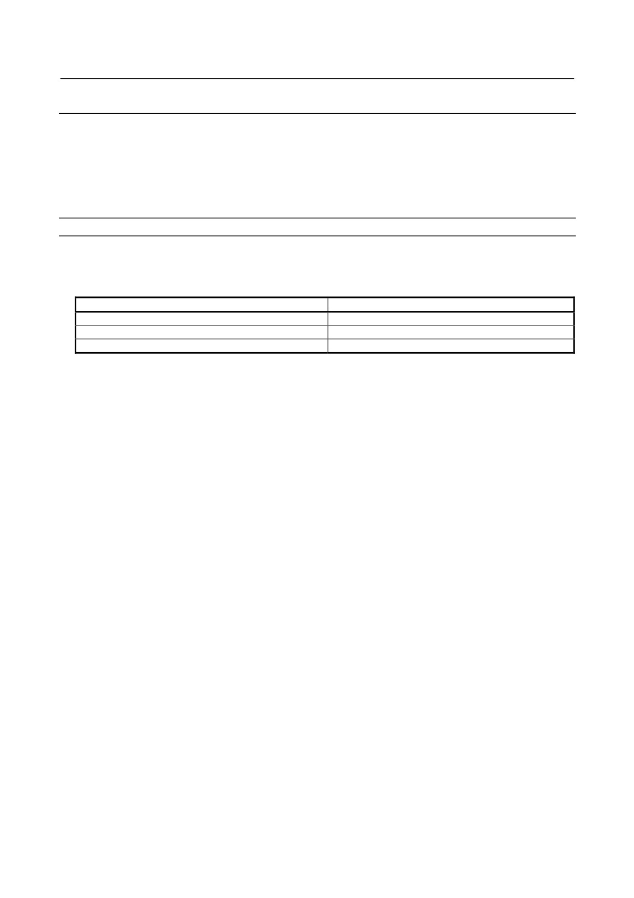
Device
Editable program
CNC built-in memory
Program in the selected path
MEMCARD
All programs
Data server
All programs
-
Number of programs editable in the background
The number of programs editable in the background is only one for each path.
-
Background editing on a 2-path system
Each path has its own editing status, background or foreground. If the editing status of path 1 is
background and that of path 2 is foreground, therefore, switching from path 1 to path 2 causes the
program of path 2 being subjected to foreground editing to be displayed on the program editing screen
and, by contrast, switching from path 2 to path 1 causes the program of path 1 being subjected to
background editing to be displayed.
In addition, if simultaneous editing of programs of the both paths is enabled (bit 0 (DHD) of parameter
No. 3106 = 1 and bit 2 (DOP) of parameter No. 3193 = 0), starting background editing for one of the
paths causes background editing for the other path to be started; hence simultaneous background editing
of programs for both the paths.
A program for one path can be displayed along with one for the other path during background editing. It
is possible to switch between the edit target programs displayed side by side for copy and paste; hence
efficient program editing.
-
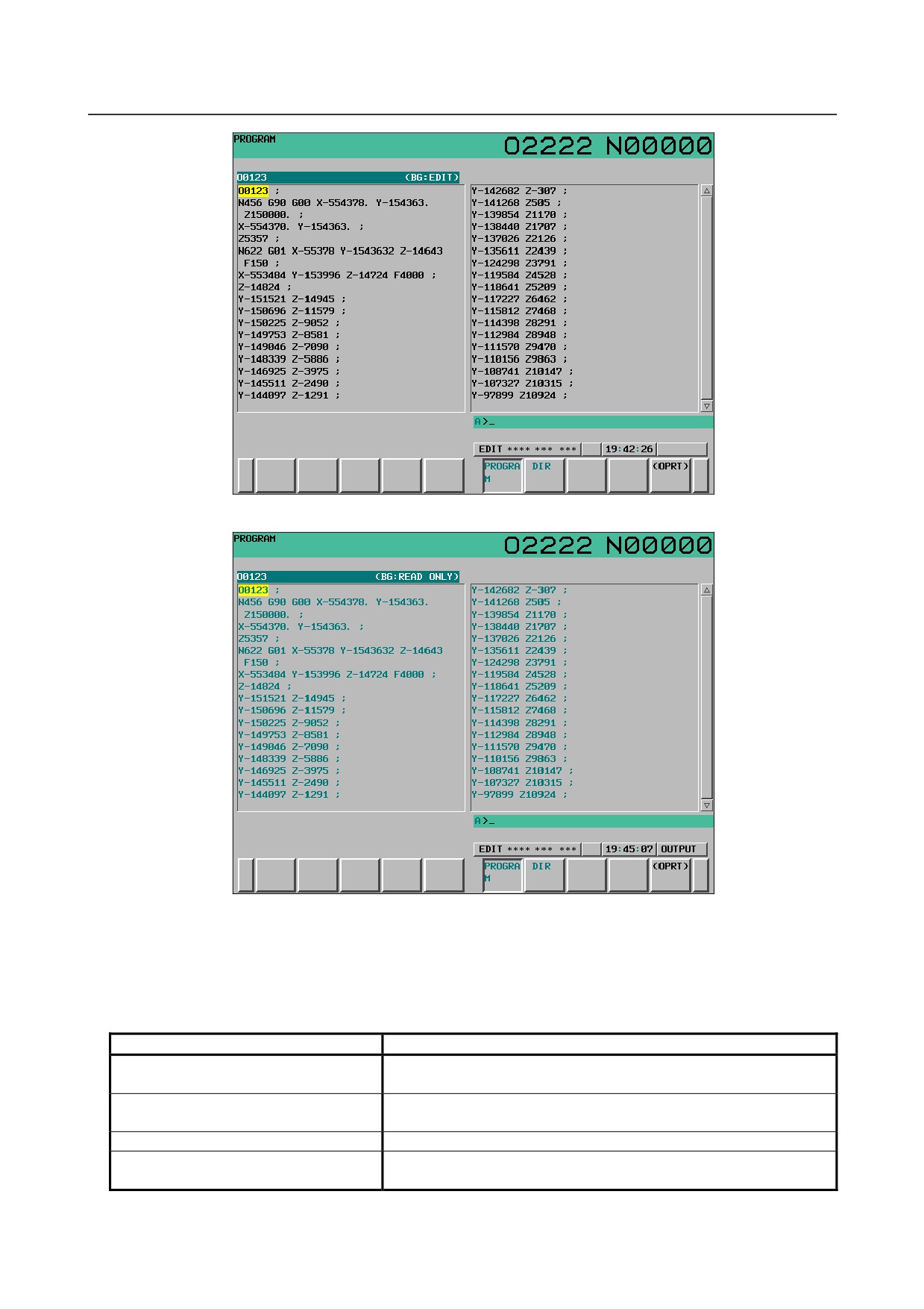
Screen display
When background editing starts, the normal editing screen is switched to the background editing screen.
The program name and "BG: EDIT", which indicates that background editing is in progress, appear in the
program status line above the program.
When background editing is performed in the reference mode, "BG: READ ONLY" appears in the
program status line. The characters are displayed in green when the program is displayed in the color
mode.
- 566 -
B-64304EN/02
OPERATION 12.SETTING AND DISPLAYING DATA
Fig. 12.2.7 (a) Screen being edited in the background (editing mode) (10.4inch)
Fig. 12.2.7 (b) Screen being edited in the background (reference mode) (10.4inch)
-
Editing status
The following items are displayed on the program status line and program editing area according to the
background editing status.
Displayed items in the program status line and editing area
Editing status
Displayed items
(BG-EDIT)
No program selected
“NO PROGRAM” is displayed in the editing area.
No program selected
(BG:READ ONLY)
Reference mode
"NO PROGRAM" is displayed in the editing area.
Program selected
program-name + (BG:EDIT)
Program selected
program-name + (BG:READ ONLY)
Reference mode, Read only
The contents of the program are displayed in green.
- 567 -
12.SETTING AND DISPLAYING DATA OPERATION
B-64304EN/02
-
Operation in the background editing
In the reference mode, a program being subject to background editing can be operated.
-
Switching to full display or small display
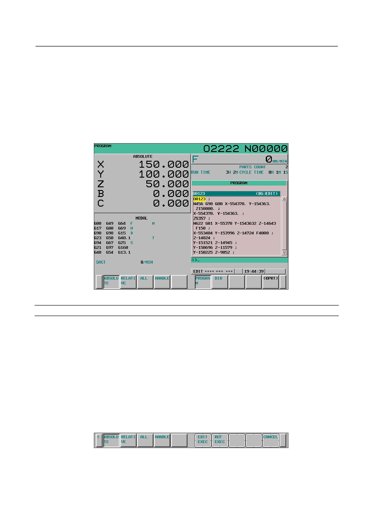
For the 10.4-inch display unit, if soft key [PROGRAM] is pressed again during the background editing,
the screen size is switched to full display or small display.
In small screen display, position display or modal display can be selected concurrently with the program
being subject to background editing.
In full screen display, much information about the program being subject to background editing can be
displayed at a time.
Fig. 12.2.7(c) Program screen (small screen) (10.4-inch)
Starting of background editing
Background editing can be started from the following screens.
PROGRAM
PROGRAM LIST
MDI PROGRAM
PROGRAM CHECK
CURRENT BLOCK
NEXT BLOCK
RESTART
Procedure
Method 1 When background editing is performed in the editing mode
1
Display a screen on which background editing can be started.
2
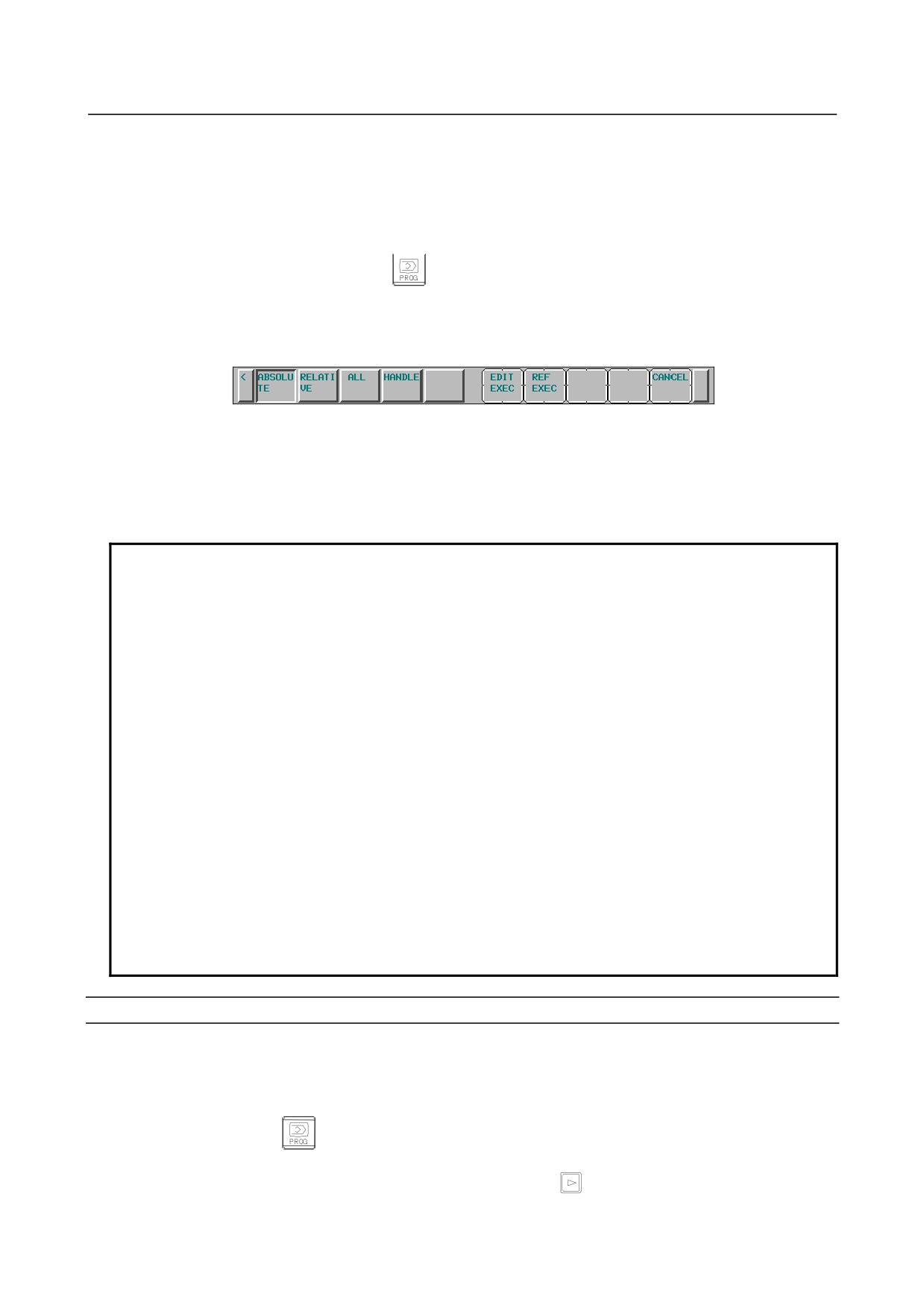
Press soft key [(OPRT)].
3
Press soft key [BG EDIT].
4
Enter the number of the program to be opened in the editing mode into the key-in
buffer.
- 568 -
B-64304EN/02
OPERATION 12.SETTING AND DISPLAYING DATA
5
Press soft key [EDIT EXEC] ([EDIT] for the 8.4-inch display unit).
The program with the entered number is opened during background editing in the
editing mode. If the program with the entered number is not present, a new
program is created and the program is opened during background editing.
Method 2 When background editing is performed in the reference mode
1
Press function key
2
Press soft key [PROGRAM].
3
Press soft key [(OPRT)].
4
Make sure that there is no character string in the key-in buffer and press soft key
[BG EDIT].
5
Enter the number of the program to be opened in the reference mode into the key-in
buffer.
6
Press soft key [REF EXEC] ([REF EXE] for the 8.4-inch display unit).
The program with the entered number is opened during background editing in the
reference mode. If the program with the entered number is not present, a warning
message “SPECIFIED PROGRAM NOT FOUND” appears
NOTE
1 A program in the place where the main program is present can be specified for
background editing (or a program in the CNC built-in memory if no main program
is present) can be specified for background editing. On the program list screen,
however, the program of the displayed device can be opened for background
editing. When editing a program not in the place where the main program is
present in the background, select the program on the program list screen.
2 When opening an O-number program for background editing, address O can be
omitted.
3 The mode selected at the start of background editing is kept until it is finished.
To switch between the editing mode and the reference mode, finish background
editing and then start background editing in the desired mode again.
4 Even when background editing is performed in the editing mode, if either of the
following programs is specified, the program is opened temporarily in the
reference mode.
- Program being operated
- Main program
5 The device for which a new program is created at the start of background editing
is only the CNC built-in memory. For the MEMCARD or data server device,
specify an existing program because no program is created.
Selecting a program subject to background editing with the cursor
When the device being displayed is the MEMCARD or data server device, the program name at the
cursor position can be stored in the key-in buffer to be opened for background editing.
Procedure
1
Press function key
2
Press soft key [DIR].
(When [LIST] is not displayed, press continuous menu key
.)
3
Press soft key [(OPRT)].
- 569 -
12.SETTING AND DISPLAYING DATA OPERATION
B-64304EN/02
4
Change the device being displayed to the MEMCARD or data server.
For changing a device, see III-11.1.
5
Move the cursor to the program to be opened for the background editing.
6
Press soft key [BG EDIT].
7
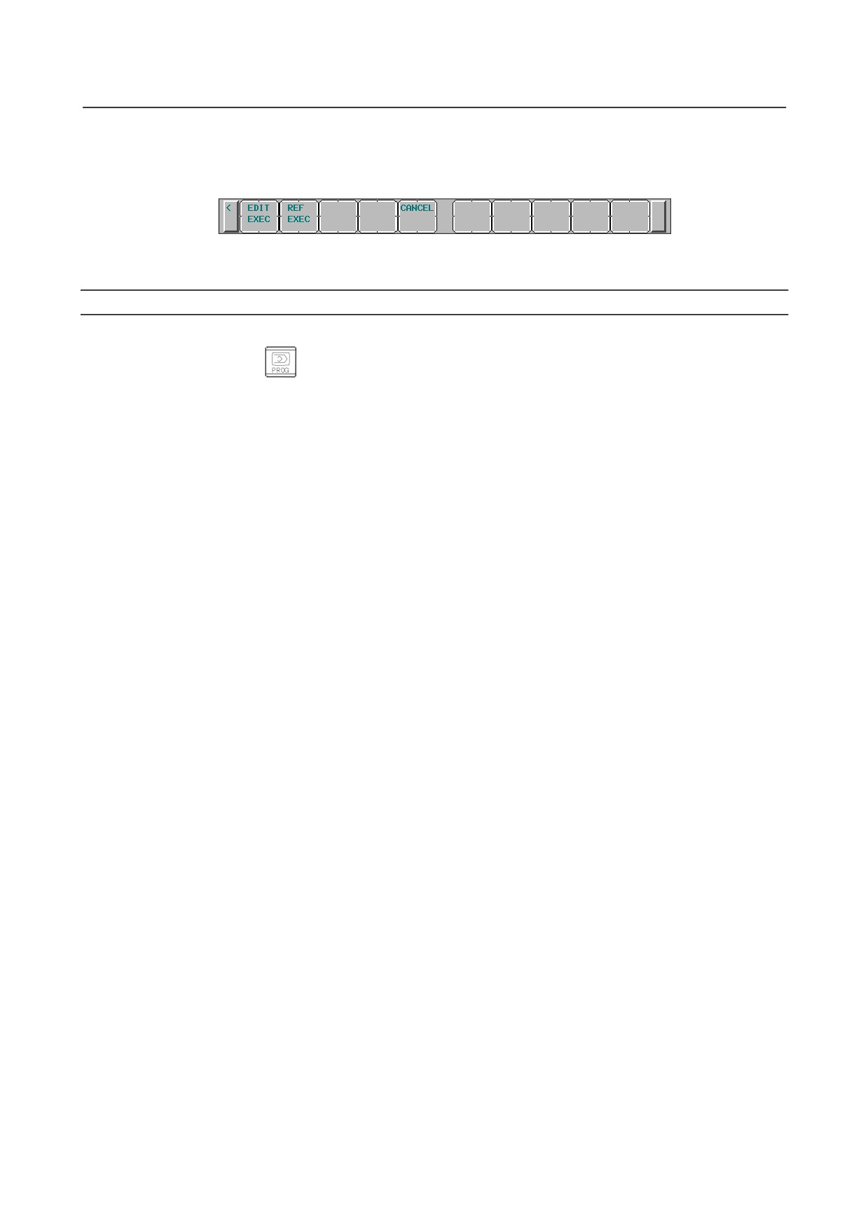
Press [EDIT EXEC] ([EDIT EXE] for the 8.4-inch display unit) or [REF EXEC] ([REF EXE] for the
8.4-inch display unit) to start background editing.
Ending background editing
Procedure
1
Press function key
2
Press soft key [PROGRAM] or [DIR].
3
Press soft key [(OPRT)] and press [BG-END].
Background editing is ended and this screen is switched to the screen in the program function last
displayed in the current CNC mode before background editing.
- 570 -
B-64304EN/02
OPERATION 12.SETTING AND DISPLAYING DATA
12.3 SCREENS DISPLAYED BY FUNCTION KEY
Section
12.3,
“SCREENS DISPLAYED BY FUNCTION KEY
”, consists of the following
subsections:
12.3.1 Displaying and Entering Setting Data
571
12.3.2 Sequence Number Comparison and Stop
574
12.3.3 Displaying and Setting Run Time, Parts Count, and Time
575
12.3.4 Displaying and Setting the Workpiece Origin Offset Value
577
12.3.5 Direct Input of Workpiece Origin Offset Value Measured
578
12.3.6 Displaying and Setting Custom Macro Common Variables
579
12.3.7 Displaying and Setting the Software Operator’s Panel
580
12.3.8 Displaying and Switching the Display Language
583
12.3.9 Protection of Data at Eight Levels
584
12.3.10 Precision Level Selection
589
12.3.11 Displaying and Setting Tool Life Management Data
591
12.3.12 Displaying and Setting Pattern Data Inputs
600
Press function key
to display or set tool compensation values and other data.
This section describes how to display or set the following data:
1.
Tool compensation value
2.
Setting data
3.
Sequence number comparison and stop
4.
Run time and part count
5.
Workpiece origin offset value
6.
Custom macro common variables
7.
Software operator’s panel
8.
Display language switching
9.
Protection of data at eight levels
10. Precision level selection
11. Tool life management data
12. Pattern data input
For information on setting an offset value for the T series and M series, refer to the Operator’s Manual (T
series) (B-64304EN-1) and the Operator’s Manual (M series) (B-64304EN-2), respectively.
The software operator’s panel, display language switching, precision level selection, and pattern data
input depend on the specifications of the machine tool builder. See the manual issued by the machine tool
builder for details.
12.3.1 Displaying and Entering Setting Data
Data such as the TV check flag and punch code is set on the setting data screen. On this screen, the
operator can also enable/disable parameter writing, enable/disable the automatic insertion of sequence
numbers in program editing, and perform settings for the sequence number comparison and stop function.
See III-9.2 for automatic insertion of sequence numbers.
See III-12.3.2 for the sequence number comparison and stop function. This subsection describes how to
set data.
Procedure for setting the setting data
Procedure
1
Select the MDI mode.
- 571 -
12.SETTING AND DISPLAYING DATA OPERATION
B-64304EN/02
2
Press function key
3
Press soft key [SETTING] to display the setting data screen.
4
This screen consists of several pages.
Press page key
or
until the desired screen is displayed.
An example of the setting data screen is shown below.
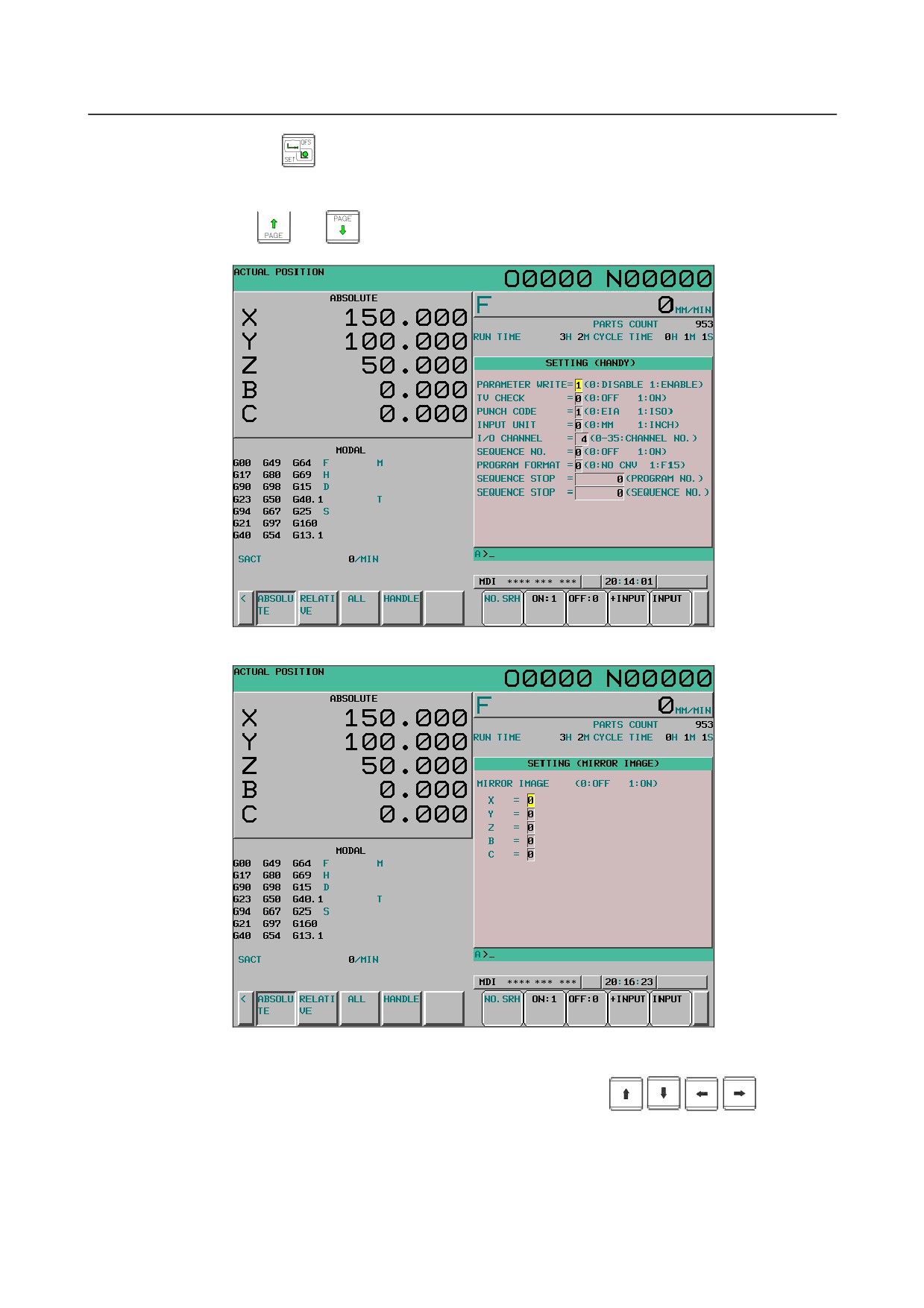
Fig. 12.3.1 (a) SETTING (HANDY) screen (10.4-inch)
Fig. 12.3.1 (b) SETTING (MIRROR IMAGE) screen (10.4-inch)
5
Move the cursor to the item to be changed by pressing cursor keys
6
Enter a new value and press soft key [INPUT].
- 572 -
B-64304EN/02
OPERATION 12.SETTING AND DISPLAYING DATA
Explanation
-
PARAMETER WRITE
Setting whether parameter writing is enabled or disabled.
0 : Disabled
1 : Enabled
-
TV CHECK
Setting to perform TV check.
0 : No TV check
1 : Perform TV check
-
PUNCH CODE
Setting code when data is output through reader/puncher interface.
0 : EIA code output
1 : ISO code output
-
INPUT UNIT
Setting a program input unit, inch or metric system
0 : Metric
1 : Inch
-
I/O CHANNEL
Using channel of reader/puncher interface.
0 : Channel 0
1 : Channel 1
2 : Channel 2
-
SEQUENCE NO.
Setting of whether to perform automatic insertion of the sequence number or not at program edit in the
EDIT mode.
0 : Does not perform automatic sequence number insertion.
1 : Perform automatic sequence number insertion.
-
PROGRAM FORMAT
Setting of whether to use the Series 10/11 format.
0: Uses the standard format.
1: Uses the Series 10/11 format.
For the Series
10/11 format, refer to Chapter II-6 in the OPERATOR’S MANUAL
(T series)
(B-64304EN-1) or Chapter II-7 of Part II in the OPERATOR’S MANUAL (M series) (B-64304EN-2).
-
SEQUENCE STOP
Setting the sequence number with which the operation stops for the sequence number comparison and
stop function and the number of the program to which the sequence number belongs
-
MIRROR IMAGE
Setting of mirror image ON/OFF for each axes.
0 : Mirror image off
1 : Mirror image on
-
Others
Page key
or
can also be pressed to display the SETTING (TIMER) screen. See III-12.3.3
for this screen.
- 573 -
12.SETTING AND DISPLAYING DATA OPERATION
B-64304EN/02
12.3.2 Sequence Number Comparison and Stop
If a block containing a specified sequence number appears in the program being executed, operation
enters single block mode after the block is executed.
Procedure for sequence number comparison and stop
Procedure
1
Select the MDI mode.
2
Press function key
3
Press chapter selection soft key [SETTING].
4
Press page key
or
several times until the following screen is displayed.
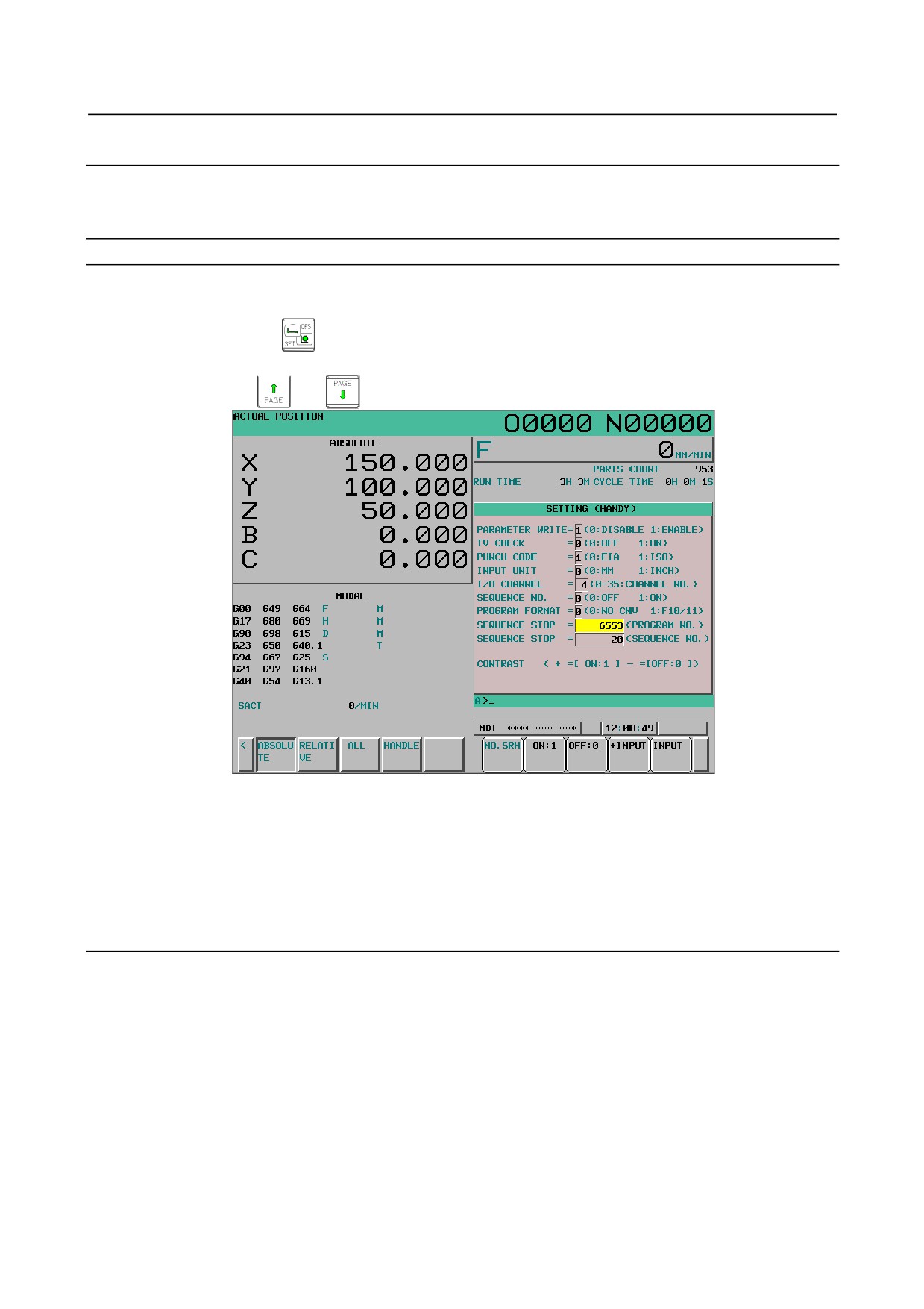
Fig. 12.3.2 (a) SETTING (HANDY) screen (10.4-inch)
5
Enter in
(PROGRAM NO.) for SEQUENCE STOP the number (1 to 9999) of the program
containing the sequence number with which operation stops.
6
Enter in (SEQUENCE NO.) for SEQUENCE STOP (with five or less digits) the sequence number
with which operation is stopped.
7
When the set program is selected and automatic operation is started, the operation makes a single
block stop at the block with the set sequence number.
Explanation
-
Sequence number after the program is executed
After the specified sequence number is found during the execution of the program, the sequence number
setting for sequence number compensation and stop becomes “-1”.
-
Exceptional blocks
If the predetermined sequence number is found in a block in which all commands are those to be
processed within the CNC control unit, the execution does not stop at that block.
[Example]N1 #1=1 ;
N2 IF[#1 EQ 1]GOTO 08 ;
N3 GOTO 09 ;
N4 M98 P1000 ;
N5 M99 ;
- 574 -
B-64304EN/02
OPERATION 12.SETTING AND DISPLAYING DATA
In the example shown above, if the predetermined sequence number is found, the execution of the
program does not stop.
-
Stop in the canned cycle
When the sequence number of the block in which the canned cycle command is present is found, the
program stops after completion of return operation of the canned cycle.
-
When the same sequence number is found several times in the program
If the predetermined sequence number appears twice or more in a program, the execution of the program
stops after the block in which the predetermined sequence number is found for the first time is executed.
-
Block to be repeated a specified number of times
If the predetermined sequence number is found in a block which is to be executed repeatedly, the
execution of the program stops after the block is executed specified times.
12.3.3 Displaying and Setting Run Time, Parts Count, and Time
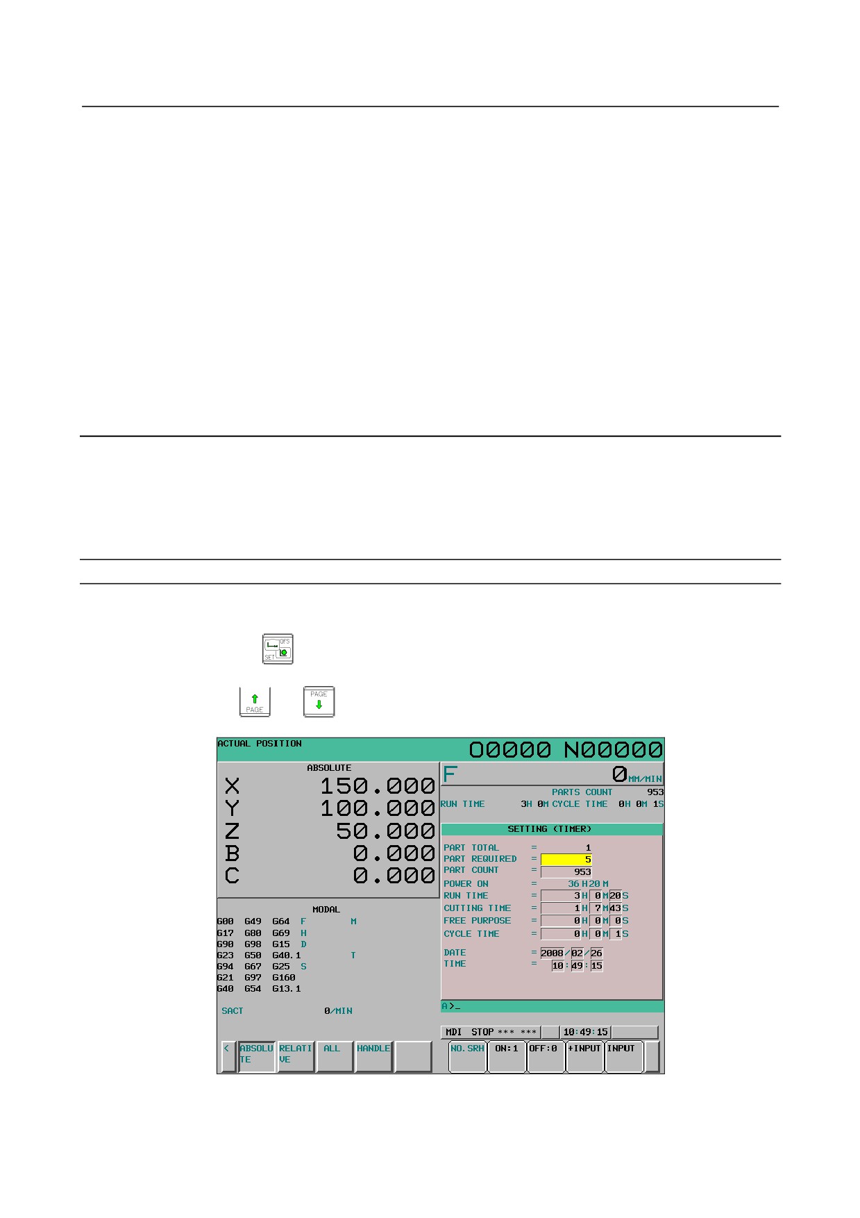
Various run times, the total number of machined parts, number of parts required, and number of machined
parts can be displayed.
This data can be set by parameters or on this screen (except for the total number of machined parts and
the time during which the power is on, which can be set only by parameters).
This screen can also display the clock time. The time can be set on the screen.
Procedure for Displaying and Setting Run Time, Parts Count and Time
Procedure
1
Select the MDI mode.
2
Press function key
3
Press chapter selection soft key [SETTING].
4
Press page key
or
several times until the following screen is displayed.
Fig. 12.3.3 (a) SETTING (TIMER) screen (10.4-inch)
- 575 -