FANUC Series 0i-MODEL D, Series 0i Mate-MODEL D. OPERATOR'S MANUAL - page 19
10.EDITING PROGRAMS
OPERATION
B-64304EN/02
If background editing is started when simultaneous 2-path program editing is enabled, background editing
is started not only with the path for which operation is performed but also with the path not selected, and
simultaneous 2-path program background editing is displayed. (Note, however, that background editing
with the path not selected is started with no program.) The edit mode specified at the start of background
editing is applied to all paths under simultaneous editing. On the simultaneous editing screen, no mixture
of the edit mode and reference mode is allowed. When a background editing end operation is performed,
background editing is ended not only with the path for which operation is performed but also with the
path not selected.
-
Simultaneous editing on 8.4-inch LCD
If the simultaneous editing screen is displayed on an 8.4-inch display unit, characters are displayed in
smaller size.
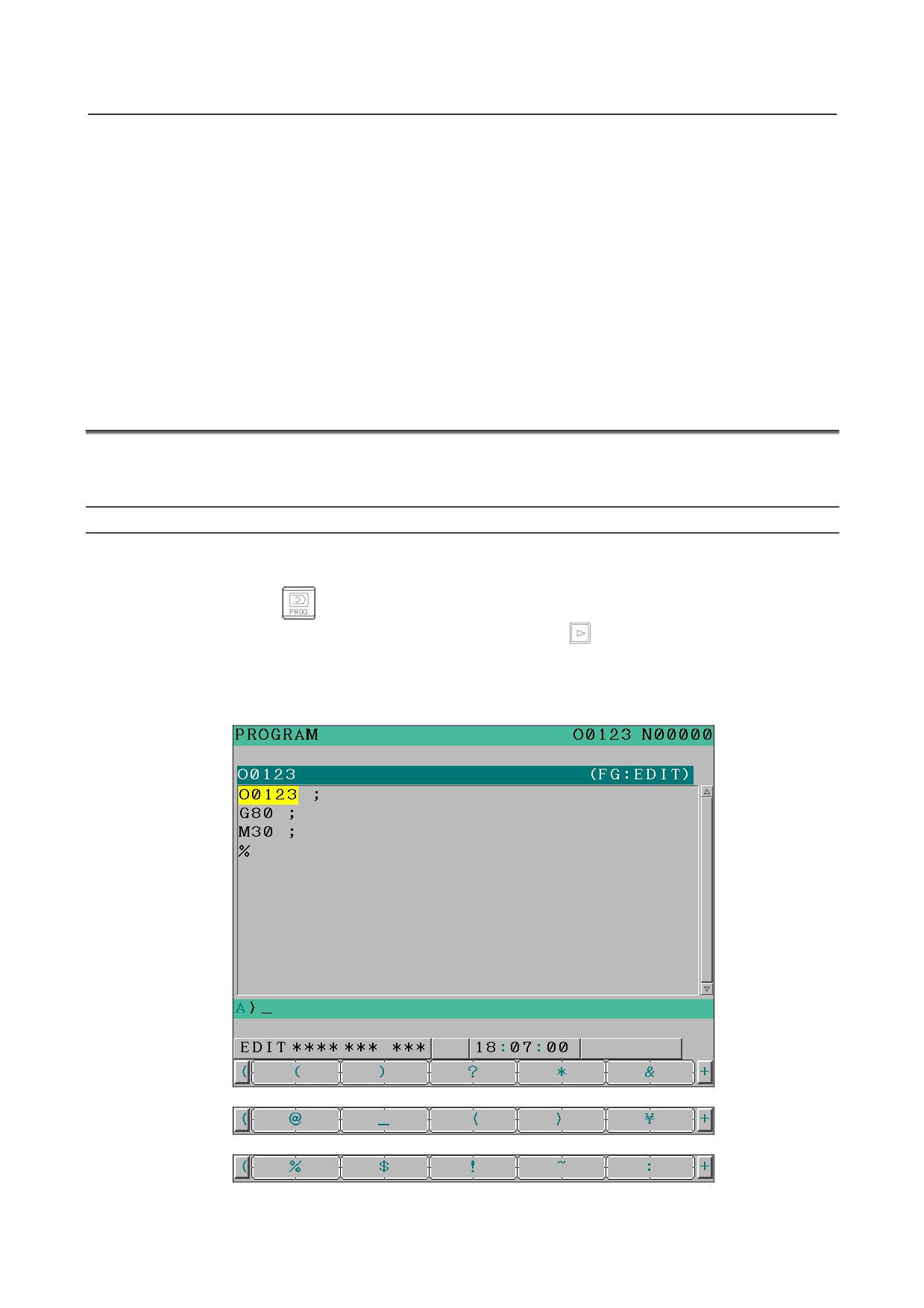
10.12 COMPACT-TYPE MDI KEY INPUT
Use of this function allows the user to enter characters such as "@", "(", and ")" by using soft keys when
the compact-type MDI unit is used.
Procedure of compact-type MDI key input
Procedure
1.
Select the EDIT mode.
2.
Press function key
3.
Press soft key [(OPRT)] then press continuous menu key
several times to display soft key
[CHA-EXT].
4.
Press soft key [CHA-EXT].
5.
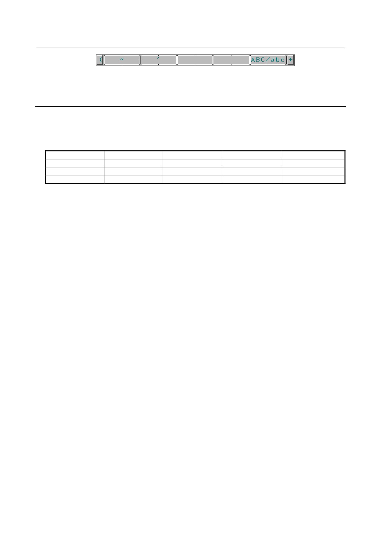
As shown in Fig. 10.12 (a), characters such as "@" and "(" appear as soft keys.
- 516 -
B-64304EN/02
OPERATION
10.EDITING PROGRAMS
Fig. 10.12 (a) Compact-type MDI key input
6.
When a soft key indicating the character to be input is pressed, the character is input to the key-in
buffer.
Explanation
-
Usable characters
The following characters can be entered using soft keys:
Table 10.12 (a) Characters that can be entered using soft keys
(
)
?
&
@
_
<
>
\
%
$
!
~
:
"
‘
AB/ab(*)
* This soft key causes the input mode of alphabetical characters to alternate between the uppercase
input mode and the lowercase input mode.
The character before the key-in buffer changes to "A" or "a" depending on the input mode.
-
Setting that inputting < > \ % $ ! ~ : " ' AB/ab become effective
Soft key input of the characters shown below and switching between the uppercase and lowercase input
modes by a soft key are enabled by setting 1 in bit 4 (SI1) of parameter No.13115.
< > \ % $ ! ~ : " '
-
Setting that inputting ( ) ? * & @ _ AB/ab become effective
Soft key input of the characters shown below and switching between the uppercase and lowercase input
modes by a soft key are enabled by setting 1 in bit 5 (SI2) of parameter No.13115.
( ) ? * & @ _
- 517 -
11.PROGRAM MANAGEMENT
OPERATION
B-64304EN/02
11 PROGRAM MANAGEMENT
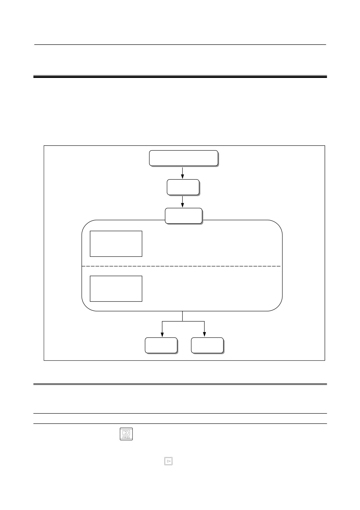
Program management functions are classified into the following two types:
• Functions for devices
• Functions for programs
The functions for devices include selection and so on.
The functions for programs include main program selection, deletion, change of names and attributes,
program compaction, and so on.
Creation and registration
Editing
Management
Selecting a device
See III-11.1.
Management of
devices
Deleting a program
See III-11.2.
Program
Changing program attributes
See III-11.3.
management
Selecting a main program
See III-11.4.
Making a program compact
See III-11.5.
Output
Execution
11.1 SELECTING A DEVICE
When the fast data server function (option) is provided, a program storage device can be selected. This
section explains the selection procedure.
Procedure for selecting a device
1
Press the function key
2
Press the soft key [DIR].
3
Press the operation selection soft key [(OPRT)].
4
Hold down the continuous menu key
until the soft key [DEVICECHANGE] (or [DEVICE]
when an 8.4-inch display unit is used) is displayed.
- 518 -
B-64304EN/02
OPERATION
11.PROGRAM MANAGEMENT
5
Press the soft key [DEVICECHANGE].
6
Press the soft key for the desired device.
11.1.1 Selecting a Memory Card Program as a Device
Overview
By selecting a memory card including a program storage file (named "FANUCPRG.BIN") as a device,
memory operation can be performed with the program in the program storage file selected as the main
program.
In addition, the content of a program storage file can be displayed on the program list screen or a program
in a program storage file can be edited on the program edit screen.
A program storage file can be created using a memory card program tool (A08B-9010-J700#ZZ11) on a
commercially available personal computer. To be used, the program storage file must be written to a
memory card formatted in FAT16 format.
(A program held in a program storage file is hereinafter referred to as a memory card program.
Moreover, a memory card storing a program storage file is referred to as a program storage memory
card.)
Procedure for selecting a device
1
Press the function key
2
Press the soft key [DIR].
3
Press the operation selection soft key [(OPRT)].
4
Hold down the continuous menu key
until the soft key [DEVICECHANGE] (or [DEVICE]
when an 8.4-inch display unit is used) is displayed.
5
Press the soft key [DEVICECHANGE].
6
Press the soft key [MEMCARD].
NOTE
A FAT16-formatted memory card containing the program storage file
FANUCPRG.BIN is recognized as a program storage memory card.
Procedure for removing a device
When a program storage memory card is replaced or a memory card is used for normal usage such as data
input/output, clear the recognition of the program storage memory card with removal operation.
1
Press the function key
2
Press the soft key [DIR].
3
Press the operation selection soft key [(OPRT)].
4
Hold down the continuous menu key
until the soft key [DEVICECHANGE] (or [DEVICE]
when an 8.4-inch display unit is used) is displayed.
5
Press the soft key [DEVICECHANGE].
6
Hold down the continuous menu key
until the soft key [UMOUNT] is displayed.
7
Press the soft key [UMOUNT].
NOTE
1 The soft key [UMOUNT] is displayed after the device selected by the CNC is
recognized as a "program storage memory card" as the result of device change
operation.
- 519 -
11.PROGRAM MANAGEMENT
OPERATION
B-64304EN/02
NOTE
2 This operation is enabled only in EDIT mode or MEM mode.
When a memory card program is selected in the main programs of two paths in
a 2-path control system, set the modes of both paths to EDIT mode or MEM
mode.
3 If the default folder is a folder in the program storage file stored on the memory
card, the default folder is changed to "//CNC_MEM/" as the result of detach
operation.
4 When the main program is a memory card program, the main program enters
the unselected state by a removal operation.
Explanation
-
About operation
A memory card program can be selected as a main program to perform memory operation.
Memory operation has the following features:
• Subprogram call nesting is allowed.
• Macro program call nesting is allowed.
• In a custom macro, a control command using a GOTO statement/WHILE statement can be specified.
-
Selection as a main program
As a main program to be automatically executed in the memory mode, a memory card program can be
selected.
However, information of having selected the memory card program as the main program is lost with the
power disconnection. (If the power disconnection and re-turning on is performed from the state of above
information, the selections are as follows.)
- The device selection is CNC_MEM.
- The main program selection is none.
-
Sub program (call using M98)
-
Macro program (call using G65/G66/M96)
The following subprogram/macro program is called:
• Sub program call (M98)
• Macro call (Simple macro call G65 / Modal call G66)
• Macro interrupt (M96)
-
Sub program (call using M code/S code/T code/particular address/the second
auxiliary function)
-
Macro program (call using G code/M code) (one touch macro call)
The following subprogram/macro program calls a program from the CNC_MEM device (CNC program
storage memory):
• Subprogram call using M code/S code/T code/particular addresses/the second auxiliary function
• Macro call using G code/M code
• One touch macro call
NOTE
For a memory card program, subprogram call using M code/S code/T
code/particular addresses/the second auxiliary function or macro call using G
code/M code can be specified. However, a program on the CNC_MEM device
(CNC program storage memory) is called.
- 520 -
B-64304EN/02
OPERATION
11.PROGRAM MANAGEMENT
-
External program number search / External workpiece number search
A program on a program storage memory card can be searched for with the external program number
search function or external workpiece number search function.
-
Main program search
The current main program is searched for. The found main program is displayed at the top of the list. The
cursor is placed on the main program.
1
Press the soft key [PROGRMSEARCH].
2
Press the soft key [MAIN SRCH].
NOTE
If a program on another device is set as the main program, executing a main
program search causes automatic switching to the device.
Limitation
For a memory card program, M198 cannot be specified. Moreover, no memory card program can be
called from a program on the CNC_MEM device (CNC program storage memory) by specifying M198.
When a setting is made to enable an external device subprogram call from a memory card (M198) or
DNC operation from a memory card (bit 7 (MNC) of parameter No. 0138 = 1), the content of program
storage file cannot be displayed during automatic operation.
When a program storage memory card is selected, the memory card cannot be used for the ordinary
purposes listed below. To use a memory card in such a case, perform a "removal" operation to cancel
the recognition of the program storage memory card.
• ALL I/O screen
Display of the contents of a memory card, and inputting/outputting data to and from a memory card
• PMC data I/O screen
Display of the contents of a memory card, and inputting/outputting to and from a memory card
• Program directory screen
Inputting/outputting program data to and from a memory card
• External device subprogram call (M198) operation
Subprogram call (M198) with a memory card set as an external device
• DNC operation
DNC operation from a memory card
CAUTION
1 Do not remove the memory card when a program that specifies a write to the
memory card is being edited. The data can be destructed.
2 If an editing operation is completed, the results of editing are preserved even
when the power to the CNC is turned off.
3 When removing the memory card, be sure to perform a "removal" operation. If
the memory card is removed without performing a "removal" operation and an
attempt is made to access the memory card, the alarm (SR1964) or alarm
(IO1030) is issued.
If the card is removed inadvertently, insert the card again and perform a "removal"
operation.
When an alarm is issued, perform the following operation:
- The power of CNC is turned off and on.
The alarm can be reset only by turning off the power to the CNC.
- 521 -
11.PROGRAM MANAGEMENT
OPERATION
B-64304EN/02
CAUTION
4 There are cases in which when a memory card is replaced with another, the CNC
cannot detect the replacement. Thus, it is risky to replace a memory card without
performing a "removal" operation, and this should never be attempted.
-
Operation of creation, edition, and management of a program
When “memory card program as a device” is selected, operation of creation, edition, and management of
a program is below:
Item
Usable
Creation of a program
Unusable
Inserting, alteration, and deletion a Word
Usable
Deletion of a block
Usable
Program search
Usable
Sequence number search
Usable
Deletion of a program
Unusable
Editing a custom macro
Usable
Password function
Unusable
Selecting a device
Usable
Selecting a main program
Usable
Making a program compact
Unusable
Input/output of program
Unusable
11.2 DELETING A PROGRAM
This section explains the procedure for deleting a program.
Procedure for deleting a file
1
Select EDIT mode.
2
Press the function key
3
Press the soft key [DIR].
4
Key in the program number of a program to be deleted.
(Press the address key
O
then key in a desired program number.)
5
Press the edit key
When the 8-level data protection function is used, the cursor appears on the program list.
In this case, select a program not with step 4 above but with the cursor key
or
NOTE
1 Depending on the operation status and protection status, a file cannot
sometimes be deleted.
2 The 8-level data protection function is optional.
- 522 -
B-64304EN/02
OPERATION
11.PROGRAM MANAGEMENT
11.3 CHANGING PROGRAM ATTRIBUTES
This section explains the procedure for changing the attribute of a program (edit disable, edit/display
disable, or protection of data at eight levels).
Procedure for selecting the attribute of a program
1
Select EDIT mode.
2
Press the function key
3
Press the soft key [DIR].
4
Press the soft key [DIR+] to display a detailed program list. (Each time the soft key [DIR+] is
pressed, the program list display switches between detailed display and normal display.)
5
Select the program of which attribute is to be changed.
Move the cursor with the cursor key
or
to a program whose attribute is to be changed.
6
Press the soft key [(OPRT)].
7
Press the soft key ['CHANGEATTRIB] (or [ATTRIB] when an 8.4-inch display unit is used).
8
Press the continuous menu key
until the desired soft key (step 8 below) appears.
9
•
To disable editing, press the soft key [EDIT DISABL] (or [EDT OFF] when an 8.4-inch display
unit is used).
•
To enable editing, press the soft key [EDIT ENABLE] (or [EDT ON] when an 8.4-inch display
unit is used).
•
To disable editing and display, press the soft key [DISP DISABL] (or [DSP OFF] when an
8.4-inch display unit is used).
•
To enable editing and display, press the soft key [DISP ENABLE] (or [DSP ON] when an
8.4-inch display unit is used).
•
To change the change protection level, type a change protection level, then press the soft key
[CHANGELEVEL] (or [CHG LEV] when an 8.4-inch display unit is used).
•
To change the output protection level, type an output protection level, then press soft key [OUT
LEVEL] (or [OUT LEV] when an 8.4-inch display unit is used).
10
Press the soft key [END].
NOTE
1 Depending on the operation status and protection status, a file cannot
sometimes be deleted.
2 Depending on the settings of the following parameters, the settable items vary:
• Program protection (parameter No. 3210 and No. 3211)
• Eight-level data protection (Optional function)
11.4 SELECTING A MAIN PROGRAM
This section explains the procedure for selecting a main program.
Procedure for selecting a main program
1
Select EDIT mode.
2
Press the function key
3
Press the soft key [DIR].
4
Key in the program number of a program to be selected as a main program.
(Press the address key
O
then key in a desired program number.)
- 523 -
11.PROGRAM MANAGEMENT
OPERATION
B-64304EN/02
5
Press the soft key [O SEARCH].
A selection can also be made by pressing the cursor key
NOTE
1 Depending on the operation status and protection status, the main program
cannot sometimes be selected.
2 The 8-level data protection function is optional.
11.5 MAKING A PROGRAM COMPACT
This section explains the procedure for making a program compact.
Procedure for making a program compact
1
Select EDIT mode.
2
Press the function key
3
Press the soft key [DIR].
4
Key in the program number of a program to be made compact.
(Press the address key
O
then key in a desired program number.)
5
Press the soft key [PROGRMCNDENS] (or [CONDENS] when an 8.4-inch display unit is used).
When the 8-level data protection function is used, the cursor appears on the program list.
In this case, select a program not with step 4 above but with the cursor key
or
NOTE
1 Depending on the operation status and protection status, a program cannot
sometimes be made compact.
2 Only programs on the CNC_MEM device can be made compact.
3 The 8-level data protection function is optional.
- 524 -
B-64304EN/02
OPERATION 12.SETTING AND DISPLAYING DATA
12 SETTING AND DISPLAYING DATA
To operate a CNC machine tool, various data must be set on the MDI panel for the CNC. The operator
can monitor the state of operation with data displayed during operation.
This chapter describes how to display and set data for each function.
Chapter 12, "SETTING AND DISPLAYING DATA", consists of the following sections:
12.1 SCREENS DISPLAYED BY FUNCTION KEY
................................................................540
12.2 SCREENS DISPLAYED BY FUNCTION KEY
................................................................555
12.3 SCREENS DISPLAYED BY FUNCTION KEY
................................................................561
12.4 SCREENS DISPLAYED BY FUNCTION KEY
................................................................592
12.5 SCREENS DISPLAYED BY FUNCTION KEY
................................................................662
12.6 DISPLAYING THE PROGRAM NUMBER, SEQUENCE NUMBER, AND STATUS, AND
WARNING MESSAGES FOR DATA SETTING OR INPUT/OUTPUT
OPERATION
662
12.7 SCREEN ERASURE FUNCTION AND AUTOMATIC SCREEN ERASURE FUNCTION
665
12.8 LOAD METER SCREEN
667
Explanation
-
Screen transition chart
The screen transition for when each function key on the MDI panel is pressed is shown below. The
subsections referenced for each screen are also shown. See the appropriate subsection for details of each
screen and the setting procedure on the screen. See other chapters for screens not described in this
chapter.
See Chapter 7 for the screen that appears when function key
is pressed. In general, function key
or
is prepared by the machine tool builder and used for macros. Refer to the manual issued
by the machine tool builder for the screen that appears when function key
or
is pressed.
-
Data protection key
The machine may have a data protection key to protect part programs, tool compensation values, setting
data, and custom macro variables. Refer to the manual issued by the machine tool builder for where the
data protection key is located and how to use it.
- 525 -
12.SETTING AND DISPLAYING DATA OPERATION
B-64304EN/02
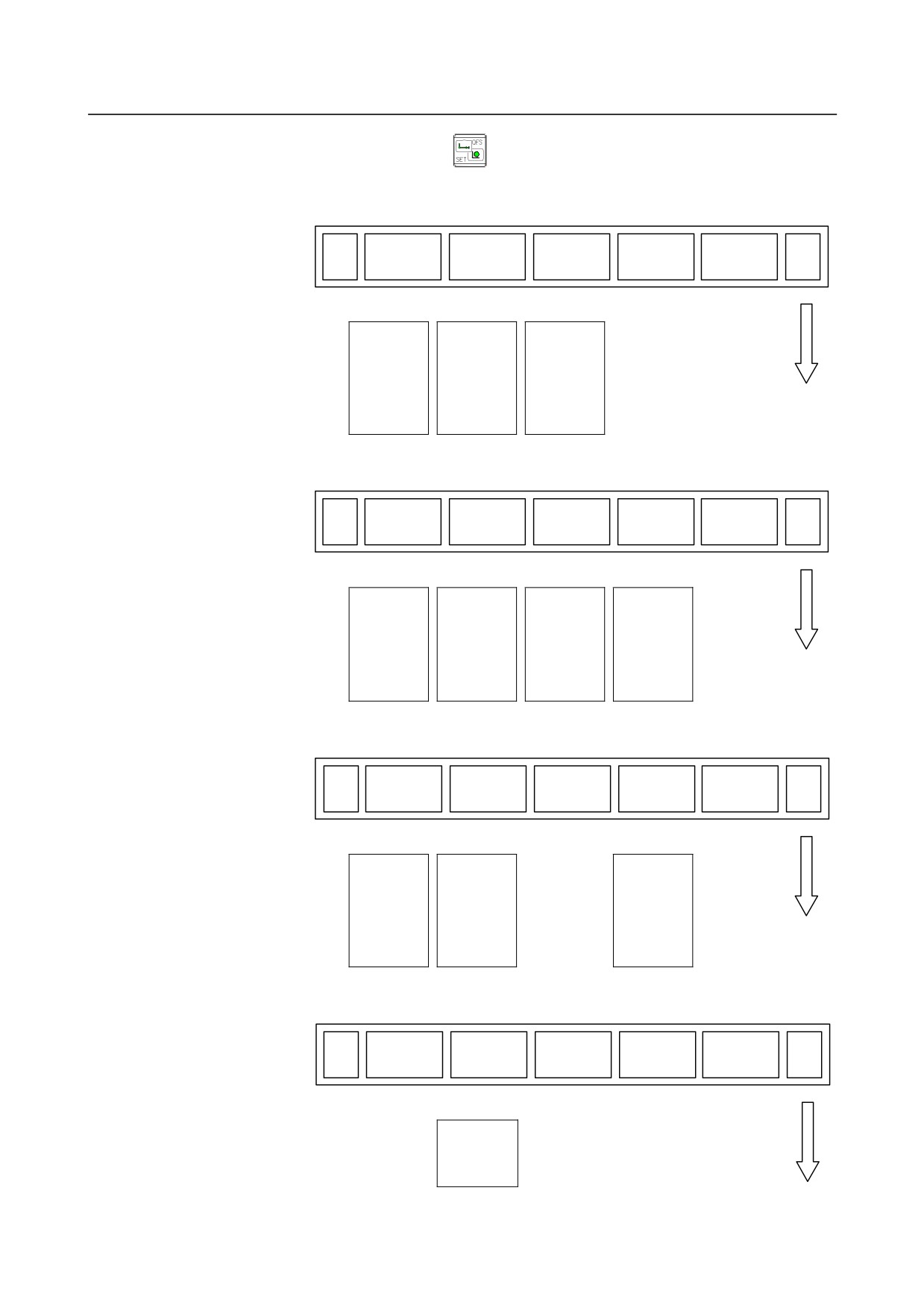
Screen displayed when the function key
is pressed (for 8.4/10.4-inch display
unit)
(1)
(2)
(3)
(4)
(5)
ABS
REL
ALL
HNDL
(OPRT)
+
Page 1
Ø
Ø
Ø
Ø
Position
Position
Position
Manual
display in
display in
display in
handle
the
the
the
interruption
workpiece
workpiece
workpiece
⇒ See III-4.6
coordinate
coordinate
coordinate
system
system
system
⇒ See III-12.1.1
⇒ See III-12.1.1
⇒ See III-12.1.1
Actual
Actual
Actual
feedrate
feedrate
feedrate
display
display
display
⇒ See III-12.1.5
⇒ See III-12.1.5
⇒ See III-12.1.5
Display of
Display of
Display of
run time
run time
run time
and parts
and parts
and parts
count
count
count
⇒ See III-12.1.6
⇒ See III-12.1.6
⇒ See III-12.1.6
(6)
(7)
(8)
(9)
(10)
MONI
(OPRT)
+
Page 2
Ø
Operating
monitor
display
⇒ See III-12.1.7
Screen displayed when the function key
is pressed (for 8.4-inch display unit)
In the MEM/RMT mode
(1)
(2)
(3)
(4)
(5)
PROGRM
CHECK
CURRENT
NEXT
(OPRT)
+
Page 1
Ø
Ø
Ø
Ø
Editing
Program
Current block
Next block
programs
check screen
display
display
⇒See III-10
⇒See III-12.2.6
screen
screen
⇒See III-12.2.7
⇒See III-12.2.5
- 526 -
B-64304EN/02
OPERATION 12.SETTING AND DISPLAYING DATA
(6)
(7)
(8)
(9)
(10)
RESTART
DIR
(OPRT)
+
Page 2
Ø
Ø
Program
Program list
restart
screen
⇒See III-4.9
⇒See III-12.2.4
In the MDI mode
(1)
(2)
(3)
(4)
(5)
PROGRM
MDI
CURRENT
NEXT
(OPRT)
+
Page 1
Ø
Ø
Ø
Ø
Editing
Program
Current block
Next block
programs
screen for
display
display
⇒See III-10
MDI operation
screen
screen
⇒See III-12.2.3
⇒See III-12.2.7
⇒See III-12.2.5
(6)
(7)
(8)
(9)
(10)
RESTART
DIR
(OPRT)
+
Page 2
Ø
Ø
Program
Program list
restart
screen
⇒See III-4.9
⇒See III-12.2.4
In the EDIT/TJOG/THND mode
(1)
(2)
(3)
(4)
(5)
PROGRM
DIR
C.A.P
(OPRT)
+
Page 1
Ø
Ø
Ø
Editing
Program list
Graphical
programs
screen
conversational
⇒See III-10
⇒See III-12.2.4
programming
screen
⇒See III-12.2.8
- 527 -
12.SETTING AND DISPLAYING DATA OPERATION
B-64304EN/02
In the JOG/HND/REF mode
(1)
(2)
(3)
(4)
(5)
PROGRM
CURRENT
NEXT
(OPRT)
+
Page 1
Ø
Ø
Ø
Editing
Current block
Next block
programs
display
display
⇒See III-10
screen
screen
⇒See III-12.2.7
⇒See III-12.2.5
(6)
(7)
(8)
(9)
(10)
RESTART
DIR
(OPRT)
+
Page 2
Ø
Ø
Program
Program list
restart
screen
⇒See III-4.9
⇒See III-12.2.4
Screen displayed when the function key
is pressed (for 10.4-inch display unit)
In the MEM/JOG/HND/RMT mode
(1)
(2)
(3)
(4)
(5)
PROGRA
NEXT
(OPRT)
+
Page 1
M
BLOCK
Ø
Ø
Editing
Next block
programs
display
⇒See III-10
screen
⇒See III-12.2.5
(6)
(7)
(8)
(9)
(10)
RESTART
DIR
(OPRT)
+
Page 2
Ø
Ø
Program
Program list
restart
screen
⇒See III-4.9
⇒See III-12.2.4
- 528 -
B-64304EN/02
OPERATION 12.SETTING AND DISPLAYING DATA
In the MDI mode
(1)
(2)
(3)
(4)
(5)
PROGRA
MDI
NEXT
(OPRT)
+
Page 1
M
BLOCK
Ø
Ø
Ø
Editing
Program
Next block
programs
screen for
display
⇒See III-10
MDI operation
screen
⇒See III-12.2.3
⇒See III-12.2.5
(6)
(7)
(8)
(9)
(10)
RESTART
DIR
(OPRT)
+
Page 2
Ø
Ø
Program
Program list
restart
screen
⇒See III-4.9
⇒See III-12.2.4
In the EDIT/TJOG/THND mode
(1)
(2)
(3)
(4)
(5)
PROGRA
DIR
C.A.P
(OPRT)
+
Page 1
M
Ø
Ø
Ø
Editing
Program list
Graphical
programs
screen
conversational
⇒See III-10
⇒See III-12.2.4
programming
screen
⇒See III-12.2.8
- 529 -
12.SETTING AND DISPLAYING DATA OPERATION
B-64304EN/02
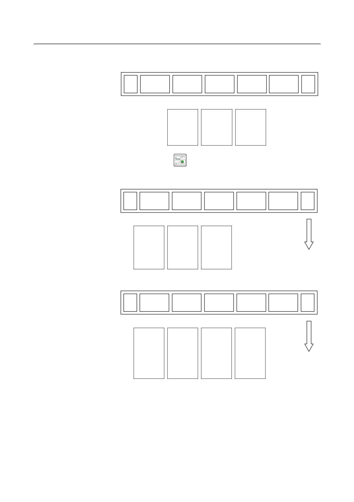
Screen displayed when the function key
is pressed (for 8.4-inch display unit)
(1)
(2)
(3)
(4)
(5)
OFFSET
SETTING
WORK
(OPRT)
+
Page 1
Ø
Ø
Ø
Setting and
Displaying
Displaying
displaying the
and entering
and setting
tool offset
setting data
the workpiece
value
⇒See III-12.3.1
origin offset
⇒See III-2.1.1*1
value
⇒See III-12.3.4
(6)
(7)
(8)
(9)
(10)
MACRO
MENU
OPR
TOOLLF
(OPRT)
+
Page 2
Ø
Ø
Ø
Ø
Displaying
Displaying
Displaying
Displaying
and setting
and setting
and setting
and setting
custom macro
pattern data
the software
tool life
common
inputs
operator’s
management
variables
⇒See III-12.3.12
panel
data
⇒See III-12.3.6
⇒See III-12.3.7
⇒See III-12.3.11
(11)
(12)
(13)
(14)
(15)
OFST.2
W.SHFT
BARRIER
(OPRT)
+
Page 3
Ø
Ø
Ø
Setting the
Setting the
Chuck and
Y-Axis offset
workpiece
tail stock
⇒See III-2.1.6*1
coordinate
barriers
system shift
⇒See III-2.1.7*1
value
⇒See III-2.1.5*1
(16)
(17)
(18)
(19)
(20)
PR-LEV
(OPRT)
+
Page 4
Ø
Precision
level selection
⇒See III-12.3.10
- 530 -
B-64304EN/02
OPERATION 12.SETTING AND DISPLAYING DATA
(21)
(22)
(23)
(24)
(25)
LANG.
PROT.
GUARD
(OPRT)
+
Page 5
Ø
Ø
Ø
Displaying
Protection of
Wrong
and switching
data at eight
operation
the display
levels
prevention
language
⇒See III-12.3.9
functions
⇒See III-12.3.8
⇒See III-6.5
Screen displayed when the function key
is pressed (for 10.4-inch display unit)
(1)
(2)
(3)
(4)
(5)
OFFSET
SETTING
WORK
(OPRT)
+
Page 1
Ø
Ø
Ø
Setting and
Displaying
Displaying
displaying the
and entering
and setting
tool offset
setting data
the workpiece
value
⇒See III-12.3.1
origin offset
⇒See III-2.1.1*1
value
⇒See III-12.3.4
(6)
(7)
(8)
(9)
(10)
MACRO
PATTERN
OPERAT
TOOL
(OPRT)
+
Page 2
MENU
PANEL
LIFE
Ø
Ø
Ø
Ø
Displaying
Displaying
Displaying
Displaying
and setting
and setting
and setting
and setting
custom macro
pattern data
the software
tool life
common
inputs
operator’s
management
variables
⇒See III-12.3.12
panel
data
⇒See III-12.3.6
⇒See III-12.3.7
⇒See III-12.3.11
- 531 -

12.SETTING AND DISPLAYING DATA OPERATION
B-64304EN/02
(11)
(12)
(13)
(14)
(15)
Y OFFSET
WORK
BARRIER
(OPRT)
+
Page 3
SHIFT
Ø
Ø
Ø
Setting the
Setting the
Chuck and
Y-Axis offset
workpiece
tail stock
⇒See III-2.1.6*1
coordinate
barriers
system shift
⇒See III-2.1.7*1
value
⇒See III-2.1.5*1
(16)
(17)
(18)
(19)
(20)
PRECI
(OPRT)
+
Page 4
LEVEL
Ø
Precision
level selection
⇒See III-12.3.10
(21)
(22)
(23)
(24)
(25)
LANGUA
PROTEC
GUARD
(OPRT)
+
Page 5
GE
T
Ø
Ø
Ø
Displaying
Protection of
Wrong
and switching
data at eight
operation
the display
levels
prevention
language
⇒See III-12.3.9
functions
⇒See III-12.3.8
⇒See III-6.5
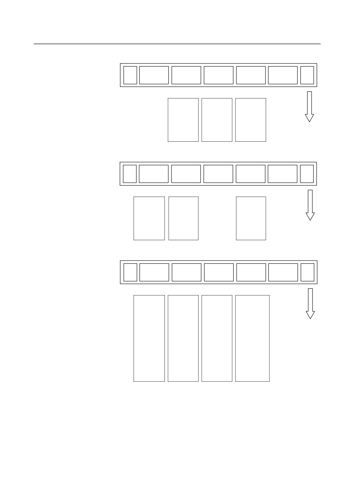
Screen displayed when the function key
is pressed (for 8.4-inch display unit)
(1)
(2)
(3)
(4)
(5)
PARAM
DGNOS
SYSTEM
(OPRT)
+
Page 1
Ø
Ø
Ø
Displaying
Checking by
System
and setting
diagnostic
configuration
parameters
display
screen
⇒See III-12.4.1
⇒See III-7.3
⇒See III-12.4.12
- 532 -
B-64304EN/02
OPERATION 12.SETTING AND DISPLAYING DATA
(6)
(7)
(8)
(9)
(10)
PITCH
SV.SET
SP.SET
(OPRT)
+
Page 2
Ø
Ø
Ø
Displaying
Servo setting
Spindle
and setting
⇒See III-12.4.3
setting
pitch error
⇒See III-12.4.5
compensation
data
⇒See III-12.4.2
(11)
(12)
(13)
(14)
(15)
W.DGNS
ALL IO
OPEHIS
(OPRT)
+
Page 3
Ø
Ø
Ø
Waveform
Input/output
Overview of
diagnosis
on the
the history
display
ALL/IO
function
⇒Maintenance
screen
⇒See III-12.4.13
manual
⇒See III-8.3
B-64305EN
(16)
(17)
(18)
(19)
(20)
PMCMNT
PMCLAD
PMCCNF
PM.MGR
(OPRT)
+
Page 4
Ø
Ø
Ø
Ø
PMC
Ladder
PMC
Power Mate
diagnosis and
diagram
configuration
CNC manager
maintenance
monitor and
data setting
functions
screens
editor screens
screens
⇒Maintenance
⇒Maintenance
⇒Maintenance
manual
manual
manual
B-64305EN
B-64305EN
B-64305EN
⇒PMC Ladder
⇒PMC Ladder
⇒PMC Ladder
Language
Language
Language
Programming
Programming
Programming
manual
manual
manual
B-64393EN
B-64393EN
B-64393EN
- 533 -
12.SETTING AND DISPLAYING DATA OPERATION
B-64304EN/02
(21)
(22)
(23)
(24)
(25)
COLOR
MAINTE
M-INFO
(OPRT)
+
Page 5
Ø
Ø
Ø
Color setting
Periodic
Maintenance
screen
maintenance
information
⇒See III-12.4.8
screen
screen
⇒See III-12.4.11
⇒Maintenance
manual
B-64305EN
(26)
(27)
(28)
(29)
(30)
FSSB
PRMSET
(OPRT)
+
Page 6
Ø
Ø
FSSB display
Parameter
and setting
setting
screen
support
⇒Maintenance
screen
manual
⇒See III-12.4.10
B-64305EN
(31)
(32)
(33)
(34)
(35)
EMBED
PCMCIA
ETHBRD
FL-net
(OPRT)
+
Page 7
Ø
Ø
Ø
Ø
Embedded
Embedded
Ethernet
FL-net
Ethernet
Ethernet
functions
functions
functions
functions
⇒Fast
⇒FL-net Board
⇒Maintenance
⇒Maintenance
Ethernet/Fast
connection
manual
manual
Data Server
manual
B-64305EN
B-64305EN
operator’s manual
B-64453EN
B-64414EN
- 534 -
B-64304EN/02
OPERATION 12.SETTING AND DISPLAYING DATA
(36)
(37)
(38)
(39)
(40)
RMTDIAG
M-TUN
(OPRT)
+
Page 8
Ø
Ø
Machine
Machining
remote
parameter
diagnosis
tuning
⇒Fast
⇒See III-12.4.9
Ethernet/Fast Data
Server operator’s
manual
B-64414EN
⇒Machine remote
diagnosis package
operator’s manual
B-63734EN
(41)
(42)
(43)
(44)
(45)
ID-INF
MEMORY
(OPRT)
+
Page 9
Ø
Displaying the
memory
contents
⇒Maintenance
manual
B-64305EN
(46)
(47)
(48)
(49)
(50)
PROF.M
PROF.S
DNET M
DNET S
(OPRT)
+
Page 10
Ø
Ø
Ø
Ø
PROFIBUS-DP
PROFIBUS-DP
DeviceNet
DeviceNet
master
slave
master
slave
functions
functions
functions
functions
⇒PROFIBUS-DP
⇒PROFIBUS-DP
⇒DeviceNet Board
⇒DeviceNet Board
Board connection
Board connection
connection manual
connection manual
manual
manual
B-64443EN
B-64443EN
B-64403EN
B-64403EN
- 535 -
12.SETTING AND DISPLAYING DATA OPERATION
B-64304EN/02
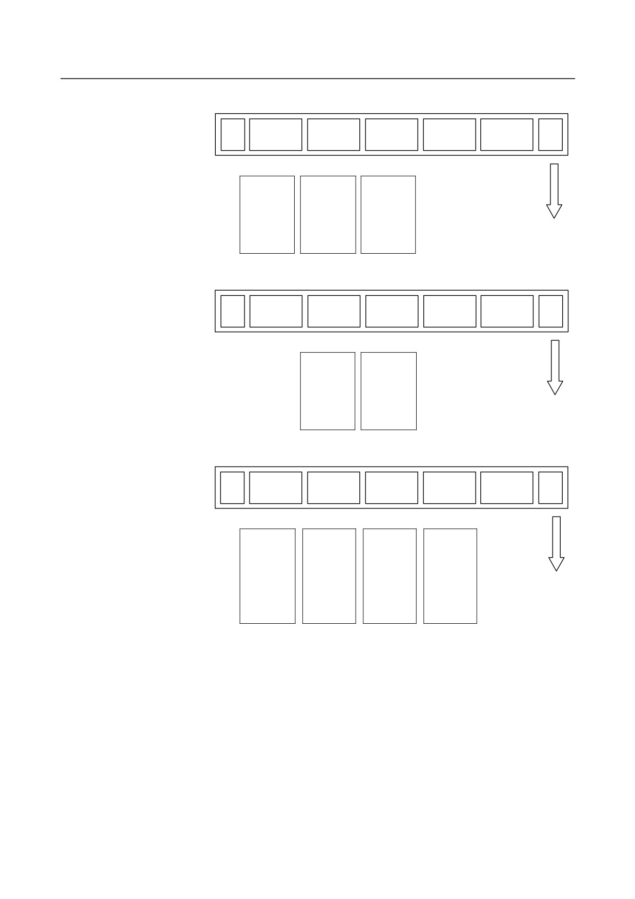
Screen displayed when the function key
is pressed (for 10.4-inch display unit)
(1)
(2)
(3)
(4)
(5)
PARAMET
DIAGNOS
SYSTEM
(OPRT)
+
Page 1
ER
IS
Ø
Ø
Ø
Displaying
Checking by
System
and setting
diagnostic
configuration
parameters
display
screen
⇒See III-12.4.1
⇒See III-7.3
⇒See III-12.4.12
(6)
(7)
(8)
(9)
(10)
PITCH
SERVO
SPINDLE
(OPRT)
+
Page 2
ERROR
SETTING
SETTING
Ø
Ø
Ø
Displaying
Servo setting
Spindle
and setting
⇒See III-12.4.3
setting
pitch error
⇒See III-12.4.5
compensation
data
⇒See III-12.4.2
(11)
(12)
(13)
(14)
(15)
WAVE
ALL IO
OPERAT
(OPRT)
+
Page 3
DIAG
HISTRY
Ø
Ø
Ø
Waveform
Input/output
Overview of
diagnosis
on the
the history
display
ALL/IO
function
⇒Maintenance
screen
⇒See III-12.4.13
manual
⇒See III-8.3
B-64305EN
- 536 -
B-64304EN/02
OPERATION 12.SETTING AND DISPLAYING DATA
(16)
(17)
(18)
(19)
(20)
PMC
PMC
PMC
P.MATE
(OPRT)
+
Page 4
MAINTE
LADDER
CONFIG
MGR.
Ø
Ø
Ø
Ø
PMC
Ladder
PMC
Power Mate
diagnosis and
diagram
configuration
CNC manager
maintenance
monitor and
data setting
functions
screens
editor screens
screens
⇒Maintenance
⇒Maintenance
⇒Maintenance
manual
manual
manual
B-64305EN
B-64305EN
B-64305EN
⇒PMC Ladder
⇒PMC Ladder
⇒PMC Ladder
Language
Language
Language
Programming
Programming
Programming
manual
manual
manual
B-64393EN
B-64393EN
B-64393EN
(21)
(22)
(23)
(24)
(25)
COLOR
PERIOD
MAINTE
(OPRT)
+
Page 5
MAINTE
INFO
Ø
Ø
Ø
Color setting
Periodic
Maintenance
screen
maintenance
information
⇒See III-12.4.8
screen
screen
⇒See III-12.4.11
⇒Maintenance
manual
B-64305EN
(26)
(27)
(28)
(29)
(30)
FSSB
PARAMET
(OPRT)
+
Page 6
ER
Ø
Ø
FSSB display
Parameter
and setting
setting
screen
support
⇒Maintenance
screen
manual
⇒See III-12.4.10
B-64305EN
- 537 -
12.SETTING AND DISPLAYING DATA OPERATION
B-64304EN/02
(31)
(32)
(33)
(34)
(35)
EMBED
PCMCIA
ETHER
FL-net
(OPRT)
+
Page 7
PORT
LAN
BOARD
Ø
Ø
Ø
Ø
Embedded
Embedded
Ethernet
FL-net
Ethernet
Ethernet
functions
functions
functions
functions
⇒Fast
⇒FL-net Board
⇒Maintenance
⇒Maintenance
Ethernet/Fast
connection
manual
manual
Data Server
manual
B-64305EN
B-64305EN
operator’s manual
B-64453EN
B-64414EN
(36)
(37)
(38)
(39)
(40)
FINE
(OPRT)
+
Page 8
TORQUE
(41)
(42)
(43)
(44)
(45)
REMOTE
MCHN
(OPRT)
+
Page 9
DIAG
TUNING
Ø
Ø
Machine
Machining
remote
parameter
diagnosis
tuning
⇒Fast
⇒See III-12.4.9
Ethernet/Fast Data
Server operator’s
manual
B-64414EN
⇒Machine remote
diagnosis package
operator’s manual
B-63734EN
(46)
(47)
(48)
(49)
(50)
ID-INF
MEMORY
(OPRT)
+
Page 10
Ø
Displaying the
memory
contents
⇒Maintenance
manual
B-64305EN
- 538 -
B-64304EN/02
OPERATION 12.SETTING AND DISPLAYING DATA
(51)
(52)
(53)
(54)
(55)
PROFI
PROFI
DEVNET
DEVNET
(OPRT)
+
Page 11
MASTER
SLAVE
MASTER
SLAVE
Ø
Ø
Ø
Ø
PROFIBUS-DP
PROFIBUS-DP
DeviceNet
DeviceNet
master
slave
master
slave
functions
functions
functions
functions
⇒PROFIBUS-DP
⇒PROFIBUS-DP
⇒DeviceNet Board
⇒DeviceNet Board
Board connection
Board connection
connection manual
connection manual
manual
manual
B-64443EN
B-64443EN
B-64403EN
B-64403EN
NOTE
For information about a dedicated screen for each control type in the T series/M
series, refer to the manuals:
*1: Operator's manual (T series) (B-64304EN-1)
*2: Operator's manual (M series) (B-64304EN-2)
- 539 -

12.SETTING AND DISPLAYING DATA OPERATION
B-64304EN/02
12.1 SCREENS DISPLAYED BY FUNCTION KEY
Section
12.1, "SCREENS DISPLAYED BY FUNCTION KEY
", consists of the following
subsections:
12.1.1 Position Display in the Workpiece Coordinate System
540
12.1.2 Position Display in the Relative Coordinate System
541
12.1.3 Overall Position Display
543
12.1.4 Workpiece Coordinate System Preset
544
12.1.5 Actual Feedrate Display
545
12.1.6 Display of Run Time and Parts Count
547
12.1.7 Operating Monitor Display
549
12.1.8 Display of Axes in 2-path System Simultaneously
550
Press function key
to display the current position of the tool.
The following three screens are used to display the current position of the tool:
• Current position display screen for the workpiece coordinate system.
• Current position display screen for the relative coordinate system.
• Current overall position display screen.
The above screens can also display the feedrate, run time, and the number of parts.
Function key
can also be used to display the load on the servo motor and spindle motor and the
rotation speed of the spindle motor (operating monitor display).
Function key
can also be used to display the screen for displaying the distance moved by handle
interruption. See III- 4.6 for details on this screen.
On any of the position display screens, the status (such as D, I, L, S, *, or M) of an axis is indicated on
the left of the axis name to prevent wrong operations. See "Axis status display" in III-6.5, "WRONG
OPERATION PREVENTION FUNCTIONS" for details.
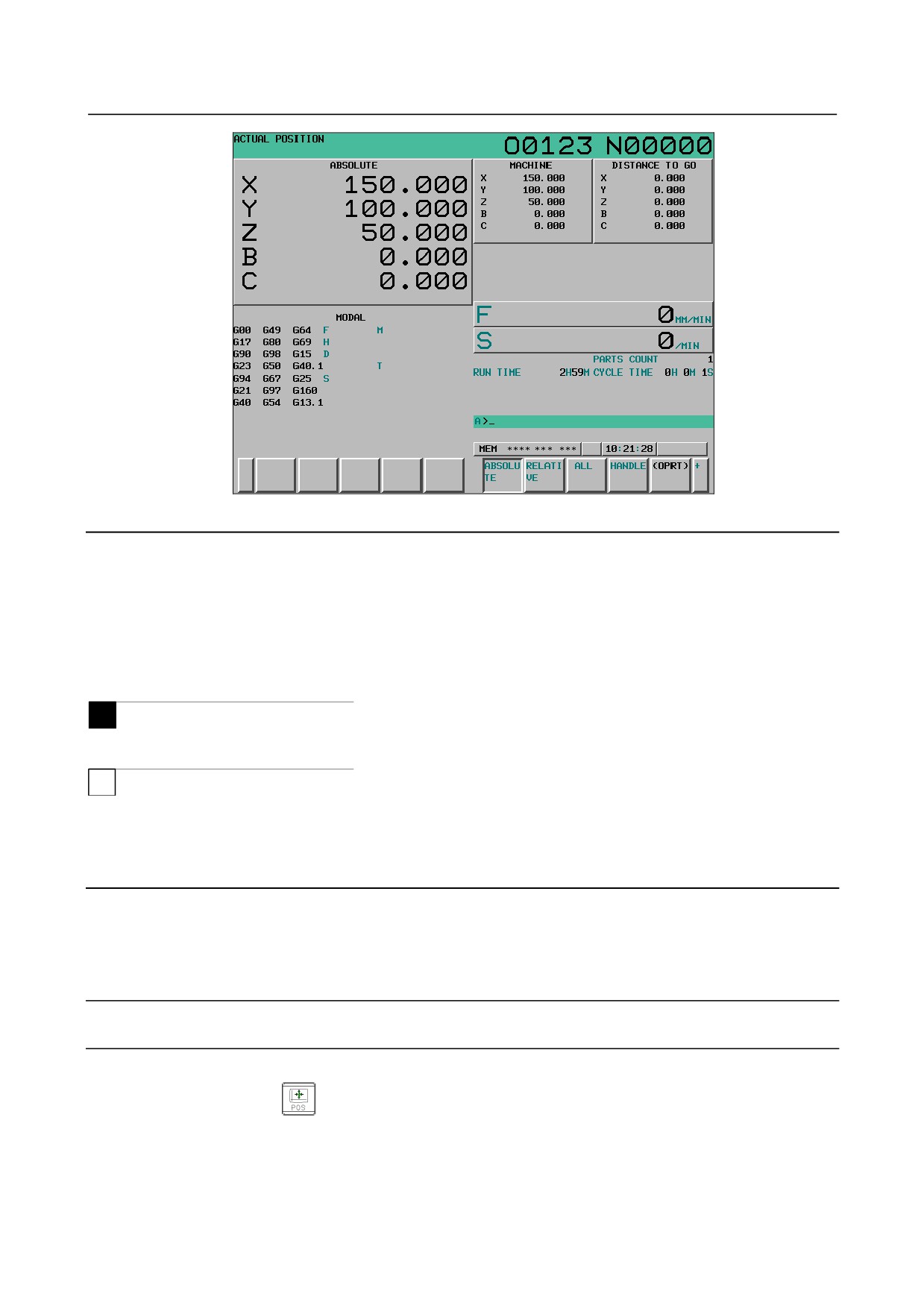
12.1.1 Position Display in the Workpiece Coordinate System
Displays the current position of the tool in the workpiece coordinate system. The current position changes
as the tool moves. The least input increment is used as the unit for numeric values. The title at the top of
the screen indicates that absolute coordinates are used.
Display procedure for the current position screen in the workpiece coordinate
Procedure
1
Press function key
2
Press chapter selection key [ABSOLUTE].
- 540 -
B-64304EN/02
OPERATION 12.SETTING AND DISPLAYING DATA
Fig. 12.1.1 (a) Current position (absolute) screen (10.4-inch)
Explanation
-
Presetting the workpiece coordinate system
A workpiece coordinate system shifted by manual intervention or other operations can be preset by MDI
operation to a workpiece coordinate system that is offset by a workpiece origin offset from the machine
zero point before shifting.
For the procedure, see Subsection 12.1.4, "Workpiece Coordinate System Preset".
-
Display including compensation values
M
Bits 6 (DAL) and 7 (DAC) of parameter No. 3104 can be used to select whether the displayed values
include tool length compensation and cutter compensation.
T
Bit 1 (DAP) parameter No. 3129 and bit 7 (DAC) of parameter No. 3104 can be used to select whether
the displayed values include tool offset and tool nose radius compensation.
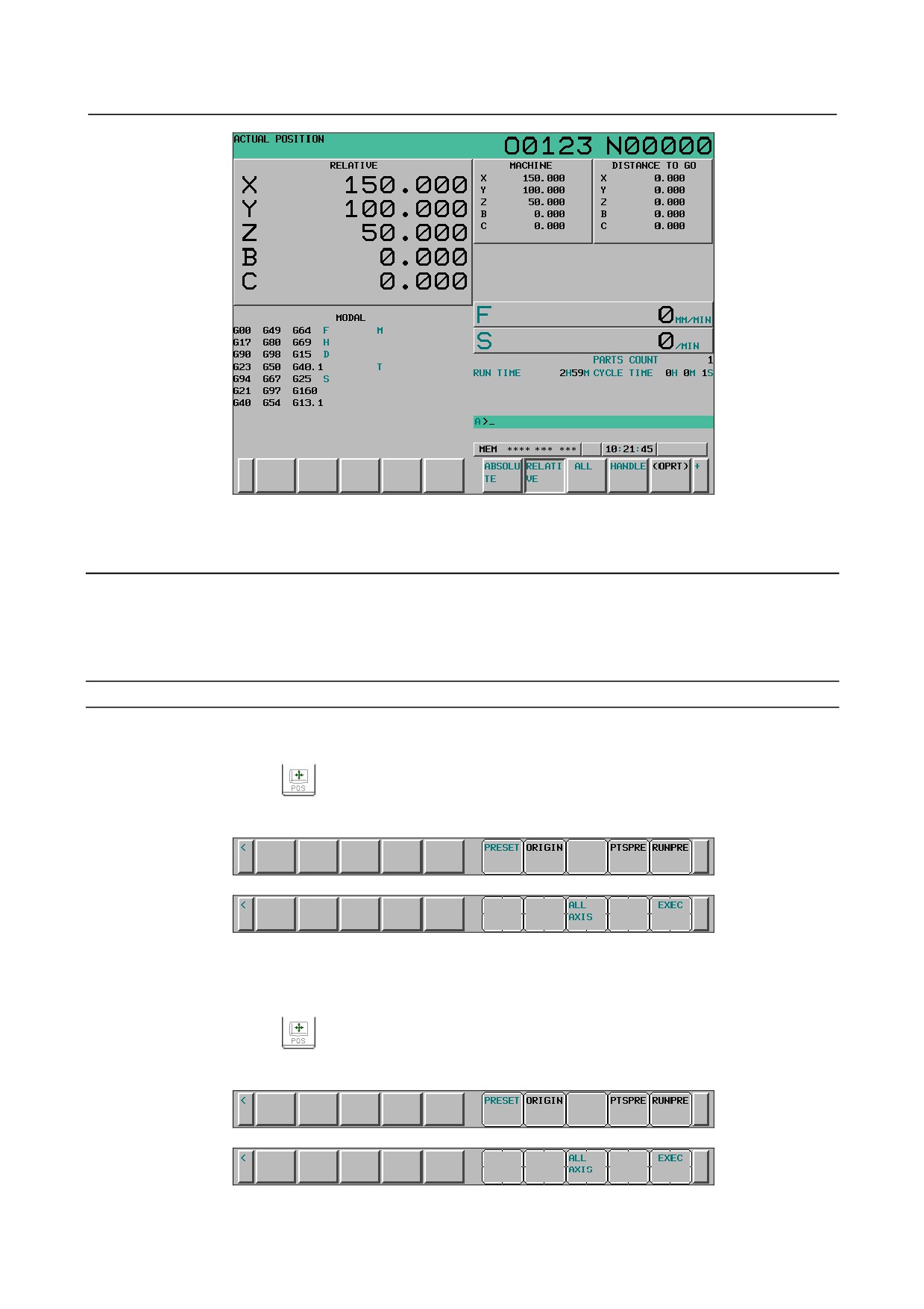
12.1.2 Position Display in the Relative Coordinate System
Displays the current position of the tool in a relative coordinate system based on the coordinates (see
Explanation) set by the operator. The current position changes as the tool moves. The increment system is
used as the unit for numeric values.
The title at the top of the screen indicates that relative coordinates are used.
Display procedure for the current position screen with the relative coordinate
system
Procedure
1
Press function key
2
Press chapter selection key [RELATIVE].
- 541 -
12.SETTING AND DISPLAYING DATA OPERATION
B-64304EN/02
Fig. 12.1.2 (a) Current position (relative) screen (10.4-inch)
See Explanation for the procedure for setting the coordinates.
Explanation
-
Setting the relative coordinates
The current position of the tool in the relative coordinate system can be reset to 0 or preset to a specified
value as follows:
Resetting relative coordinates to 0
Procedure
-
When all axes are reset to 0
1
Press function key
2
Press chapter selection key [RELATIVE] to display the relative coordinate screen.
3
Press soft key [(OPRT)].
4
Press soft key [ORIGIN].
5
Press soft key [ALL AXIS].
At this time, the current position of all axes represented in relative coordinates are reset to 0.
-
When a specified axis is reset to 0
1
Press function key
2
Press chapter selection key [RELATIVE] to display the relative coordinate screen.
3
Press soft key [(OPRT)].
4
Press soft key [ORIGIN].
5
Input the axis name with keys (the axis name blinks) and press soft key [EXEC].
- 542 -
B-64304EN/02
OPERATION 12.SETTING AND DISPLAYING DATA
At this time, the current position of the specified axis represented in relative coordinates are reset to
0.
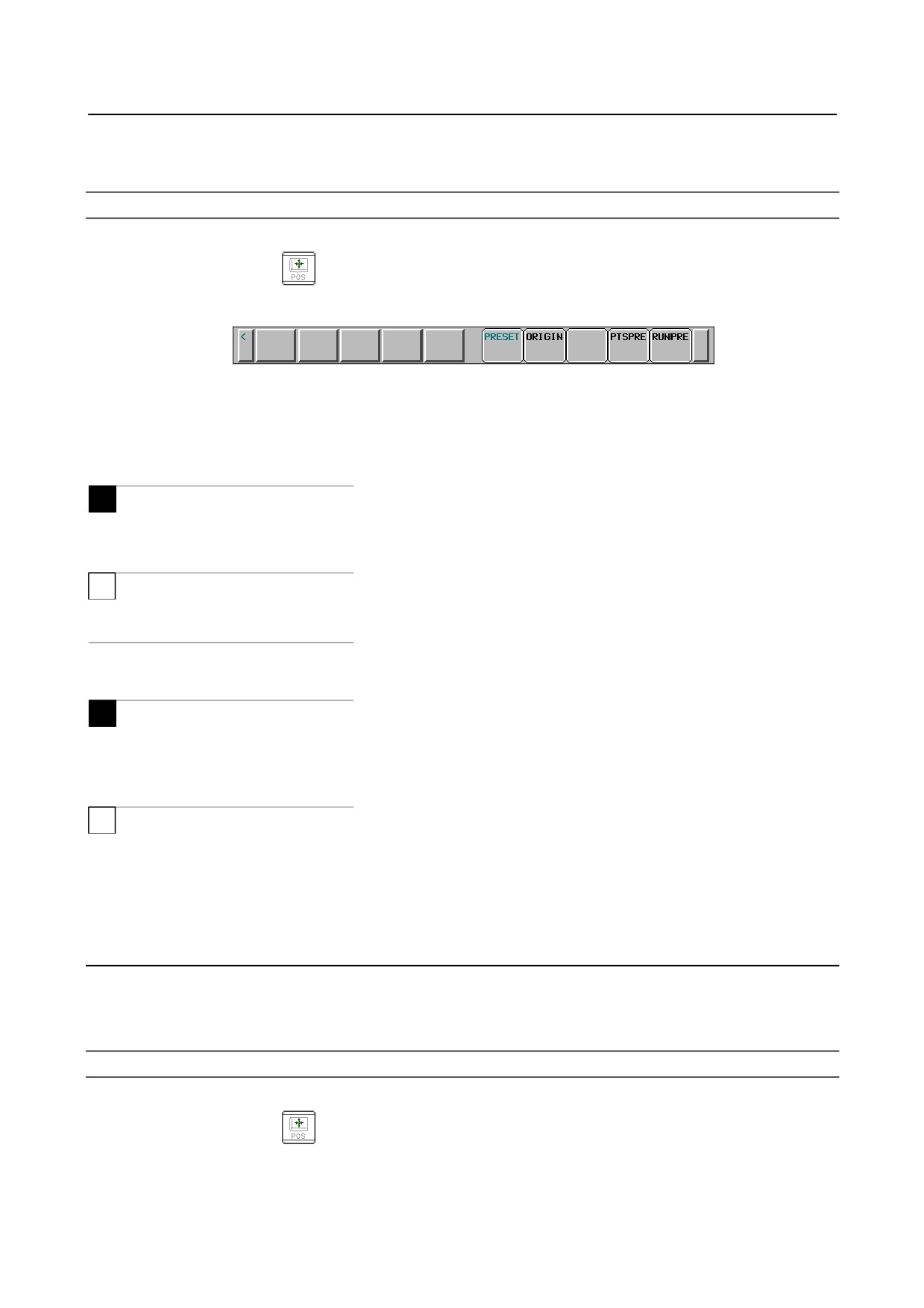
Presetting relative coordinates
Procedure
1
Press function key
2
Press chapter selection key [RELATIVE] to display the relative coordinate screen.
3
Press soft key [(OPRT)].
4
Input the axis name. At this time, the axis name blinks.
5
Input the coordinates, and press soft key [PRESET].
At this time, the current position of all axes represented in relative coordinates are set to specified
value.
-
Display including compensation values
M
Bits 4 (DRL) and 5 (DRC) of parameter No. 3104 can be used to select whether the displayed values
include tool length compensation and cutter compensation.
T
Bit 0 (DRP) parameter No. 3129 and bit 5 (DRC) of parameter No. 3104 can be used to select whether the
displayed values include tool offset and tool nose radius compensation.
-
Presetting by setting a coordinate system
M
Bit 3 (PPD) of parameter No. 3104 can be used to specify whether the position indication values in the
absolute coordinate system are preset as those in the relative coordinate system during coordinate system
setting or manual reference position return by the G92 command.
T
Bit 3 (PPD) of parameter No. 3104 can be used to specify whether the position indication values in the
absolute coordinate system are preset as those in the relative coordinate system during coordinate system
setting or manual reference position return by the G50 command (for G code system A) or G92 command
(for G code system B or C).
12.1.3 Overall Position Display
Displays the following positions on a screen : Current positions of the tool in the workpiece coordinate
system, relative coordinate system, and machine coordinate system, and the remaining distance.
The relative coordinates can also be set on this screen. See III-12.1.2 for the procedure.
Procedure for displaying overall position display screen
Procedure
1
Press function key
2
Press chapter selection key [ALL].
- 543 -
12.SETTING AND DISPLAYING DATA OPERATION
B-64304EN/02
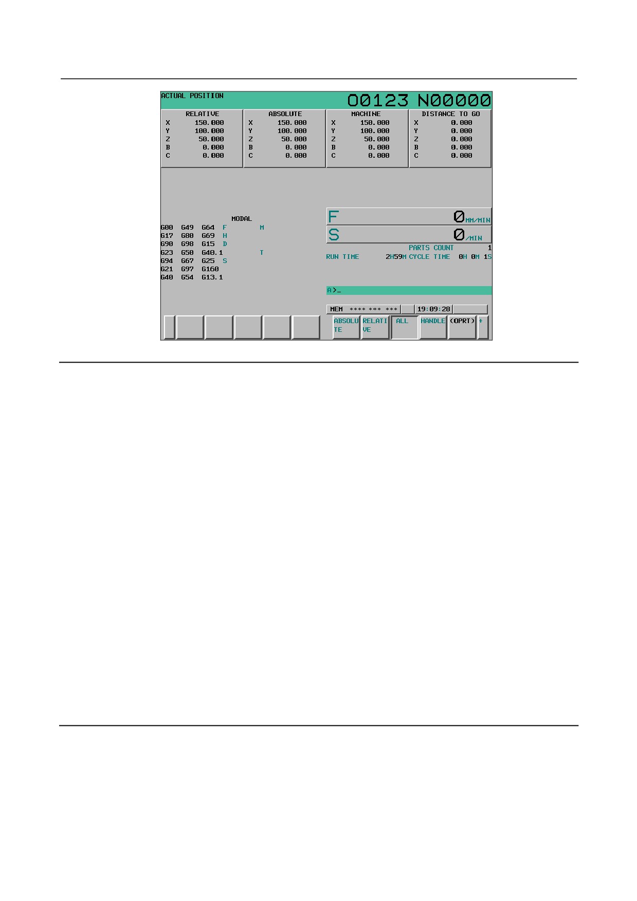
Fig. 12.1.3 (a) Current position (overall) screen (10.4-inch)
Explanation
-
Coordinate display
The current positions of the tool in the following coordinate systems are displayed at the same time:
• Current position in the relative coordinate system
(relative coordinate)
• Current position in the workpiece coordinate system
(absolute coordinate)
• Current position in the machine coordinate system
(machine coordinate)
• Distance to go (distance to go)
-
Distance to go
The distance remaining is displayed in the MEM or MDI mode.
The distance the tool is yet to be moved in the current block is displayed.
-
Machine coordinate system
The least command increment is used as the unit for values displayed in the machine coordinate system.
However, the least input increment can be used by setting bit 0 (MCN) of parameter No. 3104.
-
Resetting the relative coordinates
The total position display screen also supports the resetting of the relative coordinates to 0 or presetting of
them to specified values. See the procedure for resetting the relative coordinates described in Subsection
III-12.1.2
12.1.4 Workpiece Coordinate System Preset
If a workpiece coordinate system has been shifted with manual intervention or any other operation, an
MDI operation can be performed to preset the system to a workpiece coordinate system that is offset by a
workpiece origin offset, from the machine zero point that has been set before the shifting.
A command (G92.1) can be programmed to preset a workpiece coordinate system. (See II-7.2.4.)
- 544 -
B-64304EN/02
OPERATION 12.SETTING AND DISPLAYING DATA
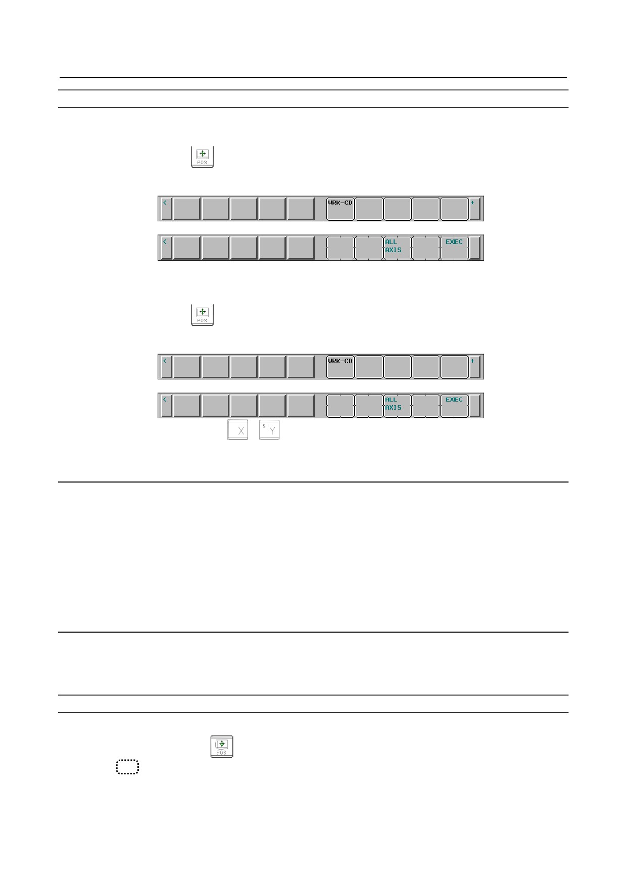
Procedure for the workpiece coordinate system preset
Procedure
-
When all axes are preset
1
Press function key
2
Press chapter selection key [ABSOLUTE] to display the absolute coordinate screen.
3
Press soft key [(OPRT)].
4
Press soft key [WRK-CD].
5
Press soft key [ALL AXIS].
-
When a specified axis is preset
1
Press function key
2
Press chapter selection key [ABSOLUTE] to display the absolute coordinate screen.
3
Press soft key [(OPRT)].
4
Press soft key [WRK-CD].
5
Enter the name of the axis (
,
, ...) to be preset with keys.
At this time, the axis name blinks.
6
Enter 0 with corresponding numeric key and press soft key [EXEC].
Explanation
-
Operation mode
This function can be executed when the reset state or automatic operation stop state is entered, regardless
of the operation mode.
-
Presetting relative coordinates
As with absolute coordinates, bit 3 (PPD) of parameter No. 3104 is used to specify whether to preset
relative coordinates.
12.1.5 Actual Feedrate Display
If bit 0 (DPF) of parameter No. 3105 is set to 1, the actual machine feed per minute (actual feedrate) or
per revolution can be indicated on the current position display screen (and the program check screen for
the 8.4-inch display unit).
Display procedure for the actual feedrate on the current position display screen
Procedure
1
Press the function key
to display a current position display screen. At the location indicated
by
, an actual feedrate is displayed.
- 545 -