FANUC Series 0i-MODEL D, Series 0i Mate-MODEL D. OPERATOR'S MANUAL - page 21
12.SETTING AND DISPLAYING DATA OPERATION
B-64304EN/02
5
To set the number of parts required, move the cursor to PARTS REQUIRED and enter the number
of parts to be machined.
6
To set the clock, move the cursor to DATE or TIME, enter a new date or time, then press soft key
[INPUT].
Explanation
-
PARTS TOTAL
This value is incremented by one when M02, M30, or an M code specified by parameter No. 6710 is
executed. This value cannot be set on this screen. Set the value in parameter No. 6712.
-
PARTS REQUIRED
It is used for setting the number of machined parts required.
When the “0” is set to it, there is no limitation to the number of parts.
Also, its setting can be made by the parameter No 6713.
-
PARTS COUNT
This value is incremented by one when M02, M30, or an M code specified by parameter No. 6710 is
executed. The value can also be set by parameter No. 6711. In general, this value is reset when it reaches
the number of parts required. Refer to the manual issued by the machine tool builder for details.
-
POWER ON
Displays the total time which the power is on. This value cannot be set on this screen but can be preset in
parameter No. 6750.
-
RUN TIME
Indicates the total run time during automatic operation, excluding the stop and feed hold time.
This value can be preset in parameter No. 6751 or No. 6752.
-
CUTTING TIME
Displays the total time taken by cutting that involves cutting feed such as linear interpolation (G01) and
circular interpolation (G02 or G03). This value can be preset in parameter No. 6753 or No. 6754.
-
FREE PURPOSE
This value can be used, for example, as the total time during which coolant flows. Refer to the manual
issued by the machine tool builder for details.
-
CYCLE TIME
Indicates the run time of one automatic operation, excluding the stop and feed hold time. This is
automatically preset to 0 when a cycle start is performed at reset state. It is preset to 0 even when power is
removed.
-
DATA and TIME
Displays the current date and time. The date and time can be set on this screen.
-
Usage
When the command of M02 or M30 is executed, the total number of machined parts and the number of
machined parts are incremented by one. Therefore, create the program so that M02 or M30 is executed
every time the processing of one part is completed. Furthermore, if an M code set to the parameter No.
6710 is executed, counting is made in the similar manner. Also, it is possible to disable counting even if
M02 or M30 is executed (bit 0 (PCM) of parameter No. 6700 is set to 1). For details, see the manual
issued by machine tool builders.
- 576 -
B-64304EN/02
OPERATION 12.SETTING AND DISPLAYING DATA
Limitation
-
Run time and part count settings
Negative value cannot be set. Also, the setting of “M” and “S” of run time is valid from 0 to 59.
Negative value may not be set to the total number of machined parts.
-
Time settings
Neither negative value nor the value exceeding the value in the following table can be set.
Table 12.3.3 (a)
Item
Maximum value
Item
Maximum value
Year
2096
Hour
23
Month
12
Minute
59
Day
31
Second
59
12.3.4 Displaying and Setting the Workpiece Origin Offset Value
Displays the workpiece origin offset for each workpiece coordinate system (G54 to G59) and external
workpiece origin offset.
The workpiece origin offset value and external workpiece origin offset value can be set on this screen.
Procedure for displaying and setting the workpiece origin offset value
Procedure
1
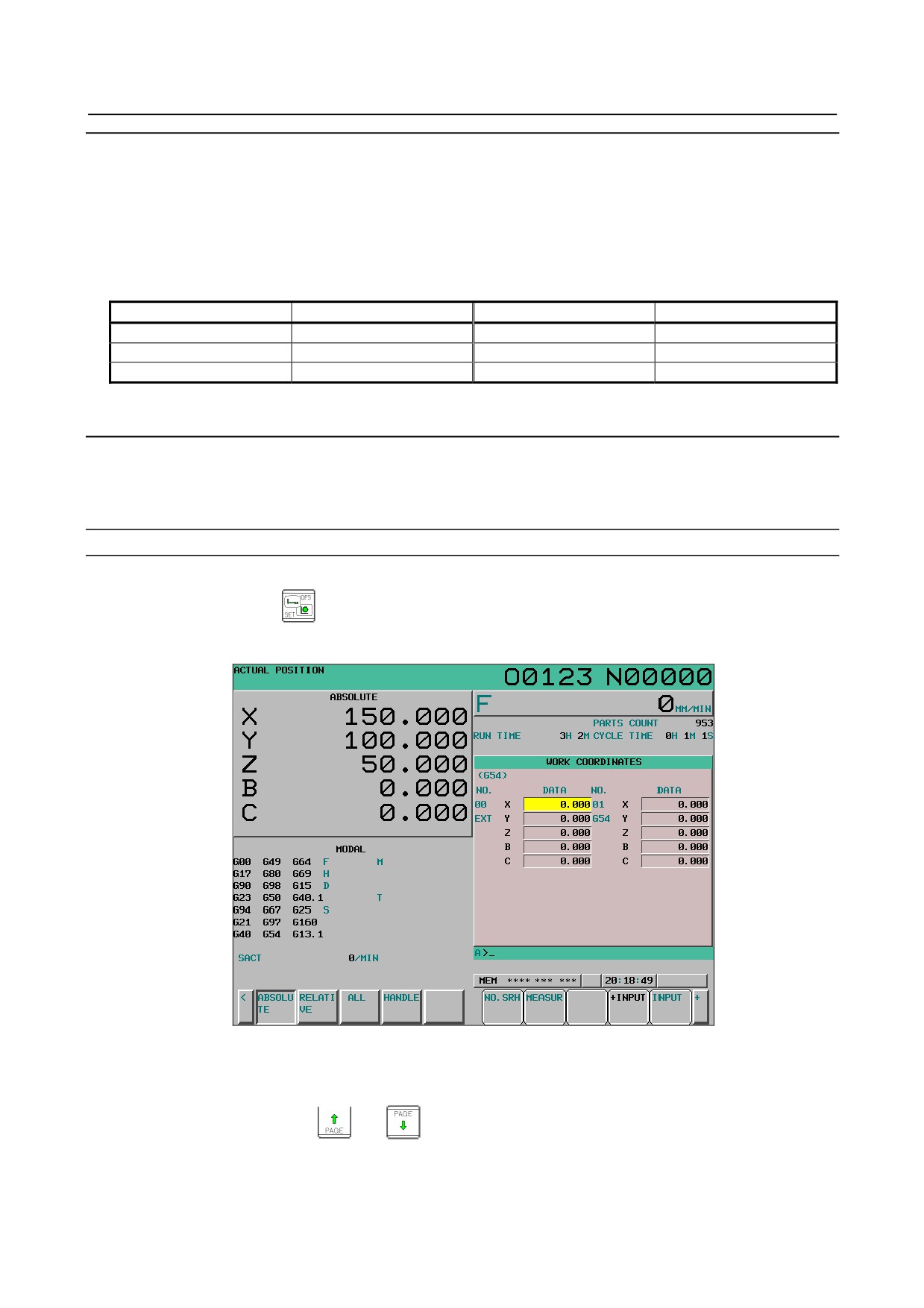
Press function key
2
Press chapter selection soft key [WORK].
The workpiece coordinate system setting screen is displayed.
Fig. 12.3.4 (a) WORK COORDINATES screen (10.4-inch)
3
The screen for displaying the workpiece origin offset values consists of two or more pages.
Display a desired page in either of the following two ways:
•
Press the page key
or
•
Enter the workpiece coordinate system number (0 : external workpiece origin offset, 1 to 6:
workpiece coordinate systems G54 to G59) and press operation selection soft key [NO.SRH].
4
Turn off the data protection key to enable writing.
5
Move the cursor to the workpiece origin offset to be changed.
- 577 -
12.SETTING AND DISPLAYING DATA OPERATION
B-64304EN/02
6
Enter a desired value by pressing numeric keys, then press soft key [INPUT]. The entered value is
specified in the workpiece origin offset value. Or, by entering a desired value with numeric keys and
pressing soft key [+INPUT], the entered value can be added to the previous offset value.
7
When performing counter input, enter the axis name in the key-in buffer and press soft key [C
INPUT] to set the relative coordinates of the specified axis.
8
Repeat steps 5, 6, and 7 to change other offset values.
9
Turn on the data protection key to disable writing.
12.3.5 Direct Input of Workpiece Origin Offset Value Measured
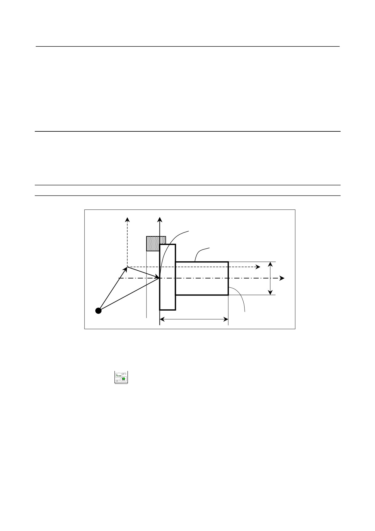
This function is used to compensate for the difference between the programmed workpiece coordinate
system and the actual workpiece coordinate system. The measured offset for the origin of the workpiece
coordinate system can be input on the screen such that the command values match the actual dimensions.
Selecting the new coordinate system matches the programmed coordinate system with the actual
coordinate system.
Procedure for direct input of workpiece origin offset value measured
Procedure
x
X
Workpiece origin assumed during
programming
Surface B
O
z
α
Previous
Z
offset
O’
New offset
β
Origin
Surface A
1
For the workpiece shown above, cut surface A in manual operation.
2
Retract the tool only in the X-axis direction without moving the Z-axis and stop the spindle.
3
Measure distance β between surface A and the programmed origin of the workpiece coordinate
system as shown above.
4
Press function key
5
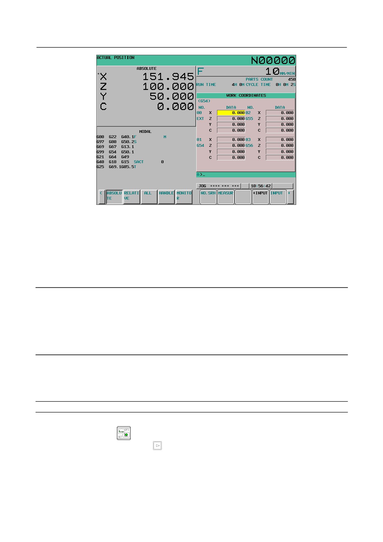
To display the WORK COORDINATES screen, press the chapter selection soft key [WORK].
- 578 -
B-64304EN/02
OPERATION 12.SETTING AND DISPLAYING DATA
Fig. 12.3.5 (a) WORK COORDINATES screen (10.4-inch)
6
Position the cursor to the workpiece origin offset value to be set.
7
Press the address key for the axis along which the offset is to be set (Z-axis in this example).
8
Enter the measured value (β) then press soft key [MEASUR].
9
Cut surface B in manual operation.
10
Retract the tool only in the Z-axis direction without moving the X-axis and stop the spindle.
11
Measure diameter α of surface B and enter this value directly as the X value as described in Steps 7
and 8.
Limitation
-
Consecutive input
Offsets for two or more axes cannot be input at the same time.
-
During program execution
This function cannot be used while a program is being executed.
12.3.6 Displaying and Setting Custom Macro Common Variables
Displays common variables (#100 to #149 or #100 to #199, and #500 to #531 or #500 to #999) on the
screen.
The values for variables can be set on this screen.
Relative coordinates can also be set to variables.
Procedure for displaying and setting custom macro common variables
Procedure
1
Press function key
2
Press the continuous menu key
, chapter selection soft key [MACRO], and soft key [(OPRT)] in
the stated order.
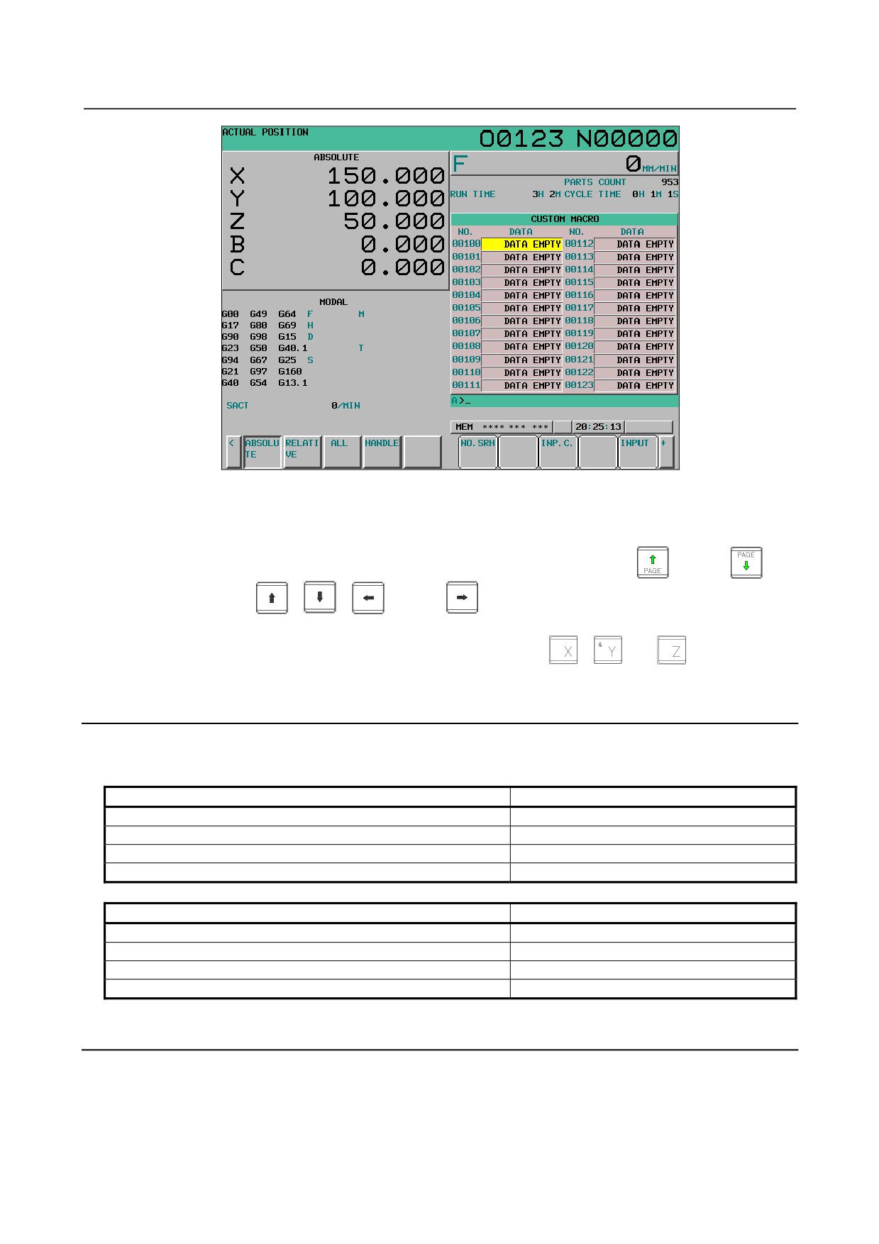
The following screen is displayed.
- 579 -
12.SETTING AND DISPLAYING DATA OPERATION
B-64304EN/02
Fig. 12.3.6 (a) CUSTOM MACRO screen (10.4-inch)
3
Move the cursor to the variable number to set using either of the following methods:
•
Enter the variable number and press soft key [NO.SRH].
•
Move the cursor to the variable number to set by pressing page keys
and/or
and
cursor keys
,
,
, and/or
4
Enter data with numeric keys and press soft key [INPUT].
5
To set a relative coordinate in a variable, press address key
,
, or
, then press soft
key [INP.C.].
6
To set a blank in a variable, just press soft key [INPUT].
Explanation
If the value of a variable produced by an operation is not displayable, an indication below is provided.
When the significant number of digits is 12 (with bit 0 (F0C) of parameter No. 6008 set to 0):
Variable value range
Variable value indication
0 < Variable value < +0.00000000001
+Underflow
0 > Variable value > -0.00000000001
-Underflow
Variable value > 999999999999
+Overflow
Variable value < -999999999999
-Overflow
When the significant number of digits is 8 (with bit 0 (F0C) of parameter No. 6008 set to 1):
Variable value range
Variable value indication
0 < Variable value < +0.0000001
+Underflow
0 > Variable value > -0.0000001
-Underflow
Variable value > 99999999
+Overflow
Variable value < -99999999
-Overflow
12.3.7 Displaying and Setting the Software Operator’s Panel
Operations on the MDI panel can substitute for the functions of switches on the machine operator’s panel.
This means that a mode selection, jog feed override selection, and so forth can be made with operations
on the MDI panel, eliminating the need to use the corresponding switches on the machine operator’s
panel.
Jog feed can be performed using numeric keys.
- 580 -
B-64304EN/02
OPERATION 12.SETTING AND DISPLAYING DATA
Procedure for displaying and setting the software operator’s panel
Procedure
1
Press function key
2
Press the continuous menu key
, then press chapter selection soft key [OPERAT PANEL]
([OPR] for the 8.4-inch display unit).
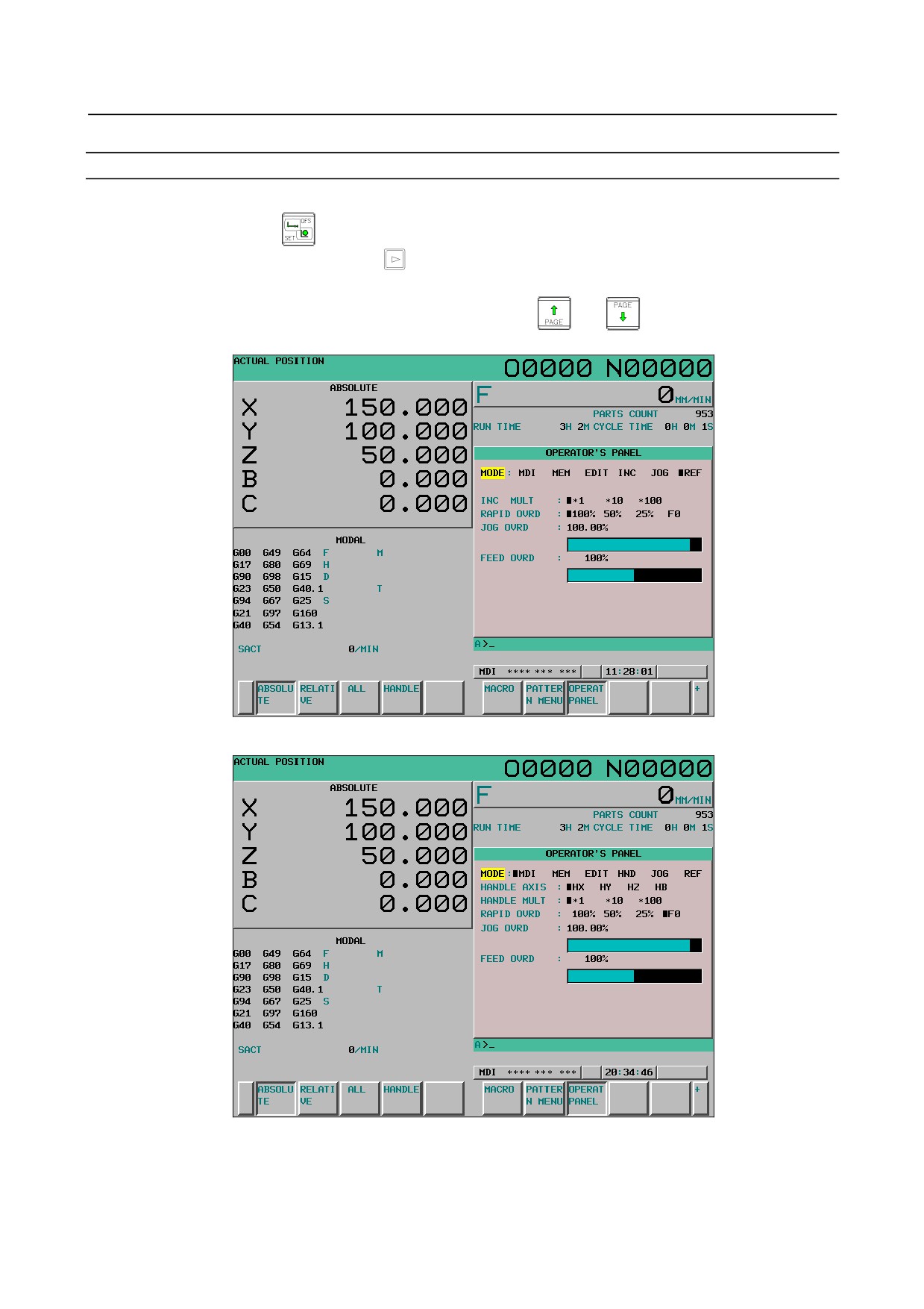
3
The screen consists of several pages. Press page key
or
until the desired screen is
displayed.
Fig. 12.3.7 (a) Example 1: Without the manual handle feed function (10.4-inch)
Fig. 12.3.7 (b) Example 2: With the manual handle feed function (10.4-inch)
- 581 -
12.SETTING AND DISPLAYING DATA OPERATION
B-64304EN/02
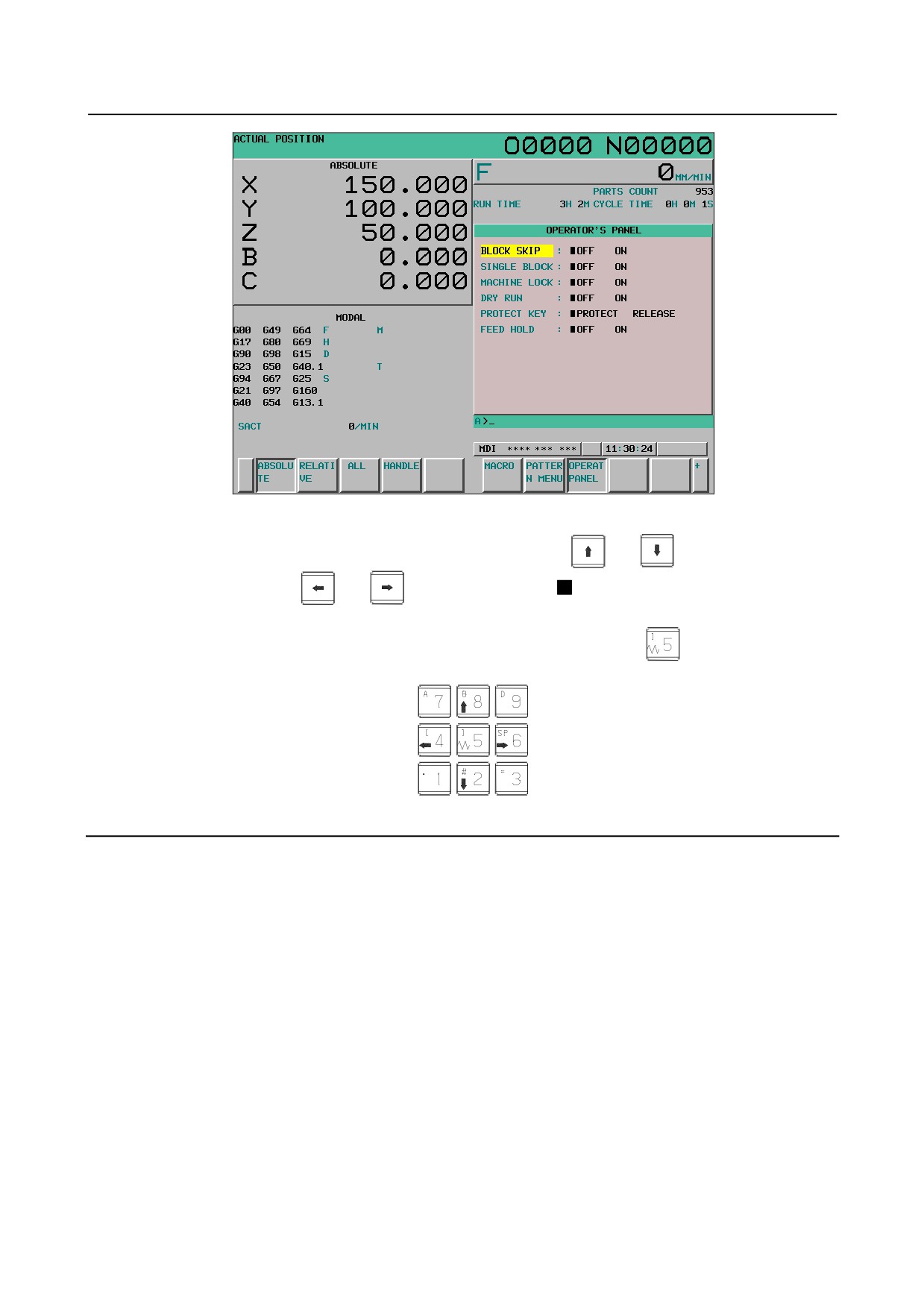
Fig. 12.3.7 (c) Example 3: (10.4-inch)
4
Move the cursor to the desired switch by pressing cursor key
or
5
Push the cursor key
or
to match the mark
to an arbitrary position and set the
desired condition.
6
Press one of the following arrow keys to perform jog feed. Press the
key together with an
arrow key to perform jog rapid traverse.
Fig. 12.3.7 (d) MDI arrow keys (T series)
Explanation
-
Valid operations
The valid operations on the software operator’s panel are shown below. Whether to use each group can
be chosen using parameter No. 7200. Those groups that are not used are not displayed on the software
operator’s panel.
Group1 : Mode selection
Group2 : Selection of jog feed axis, Manual rapid traverse
Group3 : Selection of manual pulse generator feed axis, selection of manual pulse magnification
Group4 : Jog federate, federate override, rapid traverse override
Group5 : Optional block skip, single block, machine lock, dry run
Group6 : Protect key
Group7 : Feed hold
-
Screens on which jog feed is valid
When the LCD indicates other than the software operator’s panel screen, jog feed is not conducted even if
the arrow key is pushed.
- 582 -
B-64304EN/02
OPERATION 12.SETTING AND DISPLAYING DATA
-
Jog feed and arrow keys
Parameters Nos. 7210 to 7217 are used to specify the correspondence between the arrow keys, axes, and
movement directions.
-
Feed magnification of incremental feed
The displayed item can be switched depending on whether the manual handle feed function is enabled.
When the function is enabled, the feed magnification during incremental feed is switched to the handle
magnification.
-
General purpose switches
For the meanings of these switches, refer to the manual issued by machine tool builder.
12.3.8 Displaying and Switching the Display Language
The language used for display can be switched to another language.
A display language can be set using a parameter. However, by modifying the setting of the display
language on this screen, the display language can be switched without turning off then on the power.
Displaying and setting the display language
Procedure
1
Press function key
2
Press the continuous menu key
several times.
3
Press soft key [LANGUAGE] to display the language screen.
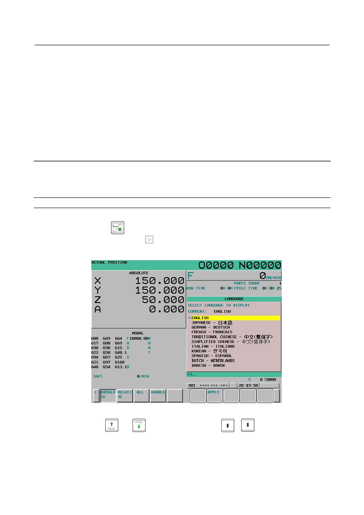
Fig. 12.3.8 (a) LANGUAGE screen (10.4-inch)
4
Press page key
or
, then press cursor keys
,
to move the cursor to a
desired display language.
5
Press operation soft key [APPLY]. The display language is switched to the selected language. The
language specified on this screen continues to be used if the power is turned off then back on.
- 583 -

12.SETTING AND DISPLAYING DATA OPERATION
B-64304EN/02
Explanation
-
Language switching
The language screen can be displayed if bit 0 (NLC) of parameter No. 3280 is set to 0.
-
Selectable languages
The display languages selectable on this screen are as follows:
1.
English
2.
Japanese
3.
German
4.
French
5.
Chinese (Traditional)
6.
Chinese (Simplified)
7.
Italian
8.
Korean
9.
Spanish
10. Dutch
11. Danish
12. Portuguese
13. Polish
14. Hungarian
15. Swedish
16. Czech
17. Russian
18. Turkish
19. Bulgarian
Among the languages listed above, English and other usable languages are displayed on the screen as a
list of switchable languages.
NOTE
The Bulgarian is optional.
Limitation
-
Language parameter modification on the parameter screen
Which language to use for display is specified with parameter No. 3281. This parameter can be modified
using the parameter screen as well. However, if a modification is made on the parameter screen, the new
setting is not reflected until “APPLY” operation is performed on the language screen or the power is
turned on again. If an invalid value is set in parameter No. 3281 on the parameter screen, the screen is
displayed in English after the power is turned on again.
12.3.9 Protection of Data at Eight Levels
You can set eight CNC and PMC operation levels and one of eight protection levels for each type of CNC
and PMC data.
When an attempt is made to change CNC and PMC data or output it to an external unit, the operation
level is compared with the protection level to determine whether to allow the change or external output.
NOTE
The 8-level data protection function is optional.
- 584 -
B-64304EN/02
OPERATION 12.SETTING AND DISPLAYING DATA
12.3.9.1 Operation level setting
You can set eight CNC and PMC operation levels.
Displaying and setting the operation level setting screen
Procedure
1
Press function key
2
Press the continuous menu key
several times until soft key [PROTECT] ([PROT.]) for the
8.4-inch display unit) is displayed.
3
Press soft key [PROTECT].
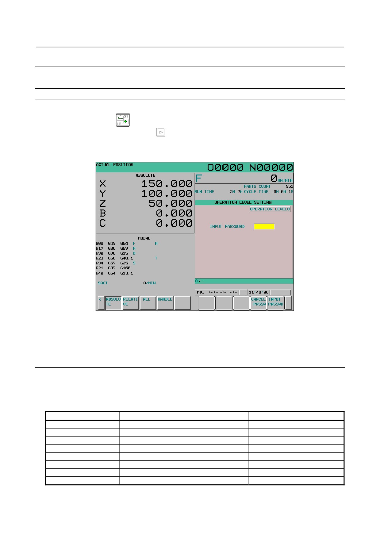
The operation level setting screen shown below is displayed.
Fig. 12.3.9.1 (a) Operation level setting screen (10.4-inch)
4
Key in the password for an operation level to be set/modified, then press soft key
[INPUT
PASSWD] ([INPUT]) for the 8.4-inch display unit).
5
To return the operation level to 0, 1, 2, or 3, press soft key [CANCEL PASSWD] ([CANCEL]) for
the 8.4-inch display unit).
Explanation
-
Operation level setting
To select operation level 0 to 3, use the corresponding memory protection key signal.
To select operation level 4 to 7, use the corresponding password.
Table 12.3.9.1 (a) Operation level setting
Operation level
Setting
Sample grouping
7 (high)
Password
-
6
Password
MTB
5
Password
Dealer and integrator
4
Password
End user
3
Memory protection key signal
User level (level 1)
2
Memory protection key signal
User level (level 2)
1
Memory protection key signal
User level (level 3)
0 (low)
Memory protection key signal
User level (level 4)
When operation level 4 to 7 is set, the operation level remains unchanged until the password is cleared.
- 585 -
12.SETTING AND DISPLAYING DATA OPERATION
B-64304EN/02
(The operation level also remains unchanged if the power is turned off.)
Operation level 7 is reserved for CNC and PMC maintenance.
NOTE
When a password is being entered, an asterisk (*) is displayed instead of each
entered character.
12.3.9.2 Password modification
The current operation level is displayed.
The password for each of operation levels 4 to 7 can be modified.
Displaying and setting the password modification screen
Procedure
1
Press function key
2
Press the continuous menu key
several times until soft key [PROTECT] ([PROT.] for the
8.4-inch display unit) is displayed.
3
Press soft key [PROTECT].
4
Press soft key [PASSWORD]([PASSWD] for the 8.4-inch display unit).
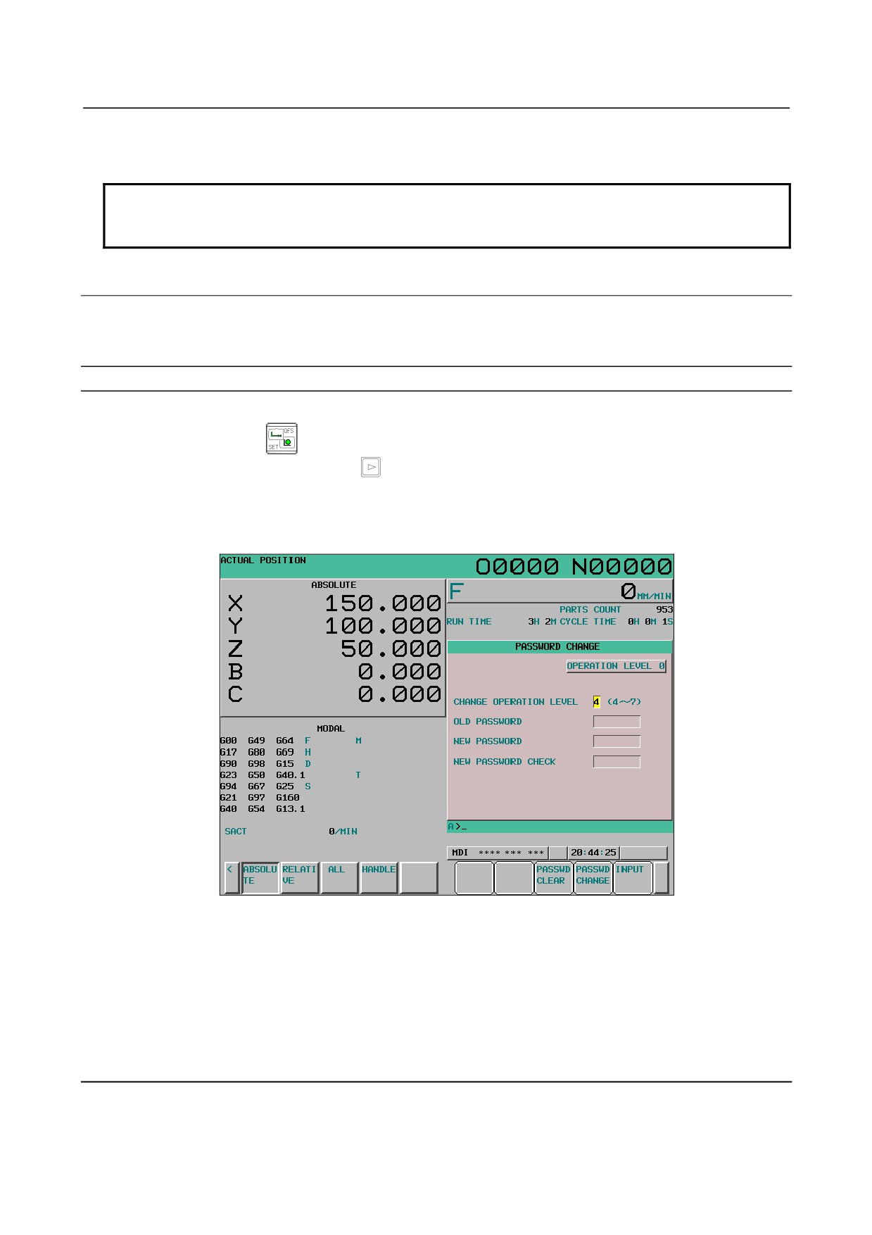
The PASSWORD CHANGE screen shown below is displayed.
Fig. 12.3.9.2 (a) PASSWORD CHANGE screen (10.4-inch)
5
Key in an operation level whose password is to be modified, then press soft key [INPUT].
6
Key in the current password for the operation level whose password is to be modified, then press
soft key [INPUT].
7
Key in a new password, then press soft key [INPUT].
8
Key in the new password again for confirmation, then press soft key [INPUT].
9
Press soft key [PASSWD CHANGE] ([CHANGE] for the 8.4-inch display unit).
10
To clear the password, press soft key [PASSWD CLEAR] ([CLEAR] for the 8.4-inch display unit).
Explanation
Up to eight characters (only uppercase alphabetic characters and numeric characters) can be input.
- 586 -

B-64304EN/02
OPERATION 12.SETTING AND DISPLAYING DATA
NOTE
1 For a password, consisting of three to eight characters, the following characters
are available:
• Uppercase alphabetic characters
• Numeric characters
2 When a password is being entered, an asterisk (*) is displayed instead of each
entered character.
3 Whether a password can be changed at the current operation level is
determined as follows:
• Password of an operation level higher than the current operation level
Cannot be changed.
• Password of the current operation level
Can be changed.
• Password of an operation level lower than the current operation level
Can be changed (only to the initial password).
4 The set password is not displayed.
Be careful not to forget the password.
12.3.9.3 Protection level setting
The current protection level is displayed.
The change protection level and output protection level of each data item are displayed.
The change protection level and output protection level of each data item can be changed.
Confirmation based on protection level setting
Procedure
1
Press function key
2
Press the continuous menu key
several times until soft key [PROTECT] ([PROT.] for the
8.4-inch display unit) is displayed.
3
Press soft key [PROTECT].
4
Press soft key [DATA LEVEL] ([PRT LV] for the 8.4-inch display unit)to change the protection
level of CNC data or press soft key [PMC LEVEL] ([PMC LV] for the 8.4-inch display unit)to
change the protection level of PMC data.
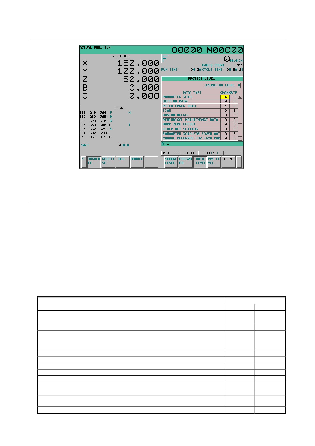
The following protection level change screen is displayed.
- 587 -
12.SETTING AND DISPLAYING DATA OPERATION
B-64304EN/02
Fig. 12.3.9.3 (a) Protection level change screen (10.4-inch)
5
Move the cursor to the change level or output level of a desired data item.
6
Key in a new desired level, then press soft key [INPUT].
Explanation
When the protection level of a data item is higher than the current operation level, the protection level of
the data item cannot be changed.
The protection level of a data item cannot be changed to a protection level higher than the current
operation level.
For each of the following types of data, you can set a data protection level. There are the following two
types of data protection levels:
• Change protection level
Sets the protection level used when data is changed.
• Output protection level
Sets the protection level used when data is output to an external unit.
As a protection level, you can set a value of 0 (low) to 7 (high).
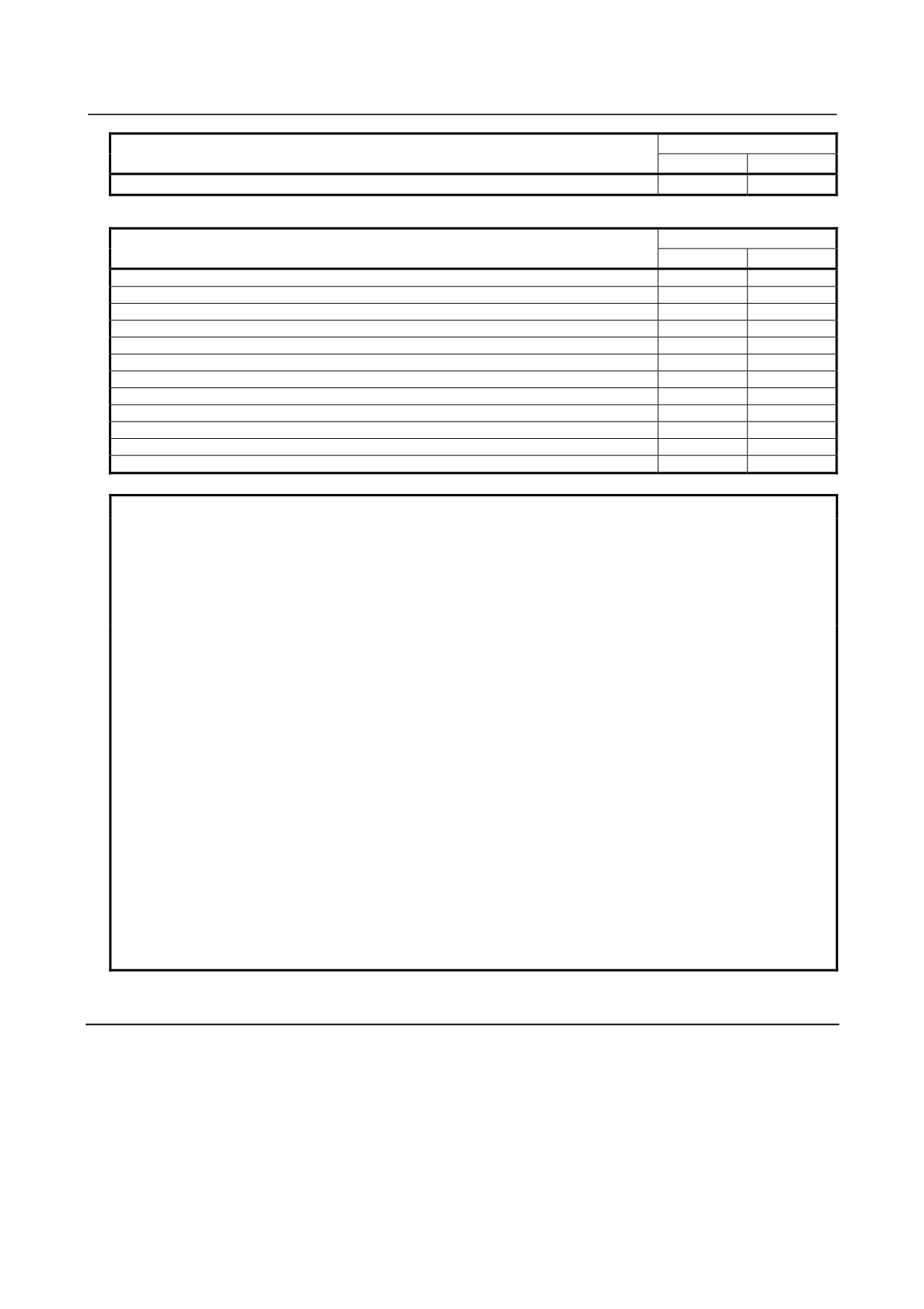
Table 12.3.9.3 (a) Protection level of each type of data
Initial protection level
Type of data
Change
Output
Custom macro variable data <CUSTOM MACRO>
0
0
(including variable data dedicated to the macro executor)
Periodical maintenance data <PERIODICAL MAINTENANCE DATA>
0
0
Tool offset data <TOOL OFFSET DATA>
(For each type when tool geometry compensation and tool wear compensation are
0
0
treated differently)
Clock data <TIME>
0
0
Workpiece origin shift amount data <WORK ZERO SHIFT>
0
0
Workpiece origin offset data <WORK ZERO OFFSET>
0
0
Ethernet setting data <ETHER NET SETTING>
0
0
Parameter data <PARAMETER DATA>
4
0
Settings <SETTING DATA>
0
0
Pitch error compensation data <PITCH ERROR DATA>
4
0
Parameter data for Power Mate CNC manager function
0
0
<PARAMETER DATA FOR POWER MATE CNC MANAGER>
Part program editing operation <CHANGE PROGRAMS FOR EACH PARTS>
0
0
- 588 -
B-64304EN/02
OPERATION 12.SETTING AND DISPLAYING DATA
Initial protection level
Type of data
Change
Output
Absolute coordinate preset operation <PRESET OF ABSOLUTE AXIS DATA>
0
0
Table 12.3.9.3 (b) Protection level of PMC data
Initial protection level
Type of data
Change
Output
Composition parameter
0
0
Setting (online)
0
0
Setting (each path)
0
0
Sequence program
0
0
PMC parameter
0
0
Timer
0
0
Counter
0
0
Keep relay
0
0
Keep relay (system)
0
0
Data table
0
0
Data table control
0
0
PMC memory
0
0
NOTE
1 For some types of data, the output function is not provided.
2 When the protection level of data is higher than the current operation level, the
protection level cannot be changed.
3 The protection level of data cannot be changed to a level higher than the current
operation level.
4 Settable types of data increase or decrease, depending on the option
configuration.
5 For details on the protection level of PMC data, refer to “PMC Programming
Manual (B-64393EN)”.
6 The type of tool offset data put in effect varies depending on the tool
compensation value memory used.
7 To change the protection level for each part program, do so on the PROGRAM
FOLDER screen rather than on the PROTECT LEVEL screen.
8 Part program editing includes program editing for the MDI mode.
9 Presetting absolute coordinates causes preset workpiece coordinate system
values to be protected.
10 During tool offset data input/output, if any tool offset data type is not allowed to
be changed or output to the outside, it is processed as follows:
- Input
: Any data type other than those whose change is not allowed is
changed.
- Output : Any data type other than those whose change is not allowed is output.
12.3.10 Precision Level Selection
An intermediate precision level between the parameters for emphasis on velocity (precision level 1) and
the parameters for emphasis on precision (precision level 10) set on the machining parameter tuning
screen can be selected. As shown in the figure below, the levels are proportionally linear, and an
intermediate level can be selected so that optimal parameters can be automatically calculated to perform
machining.
- 589 -
12.SETTING AND DISPLAYING DATA OPERATION
B-64304EN/02
Value
RMS value
1
10 Precision level
(RMS value: Root-Mean-Square value)
Fig. 12.3.10 (a) Image of “level”
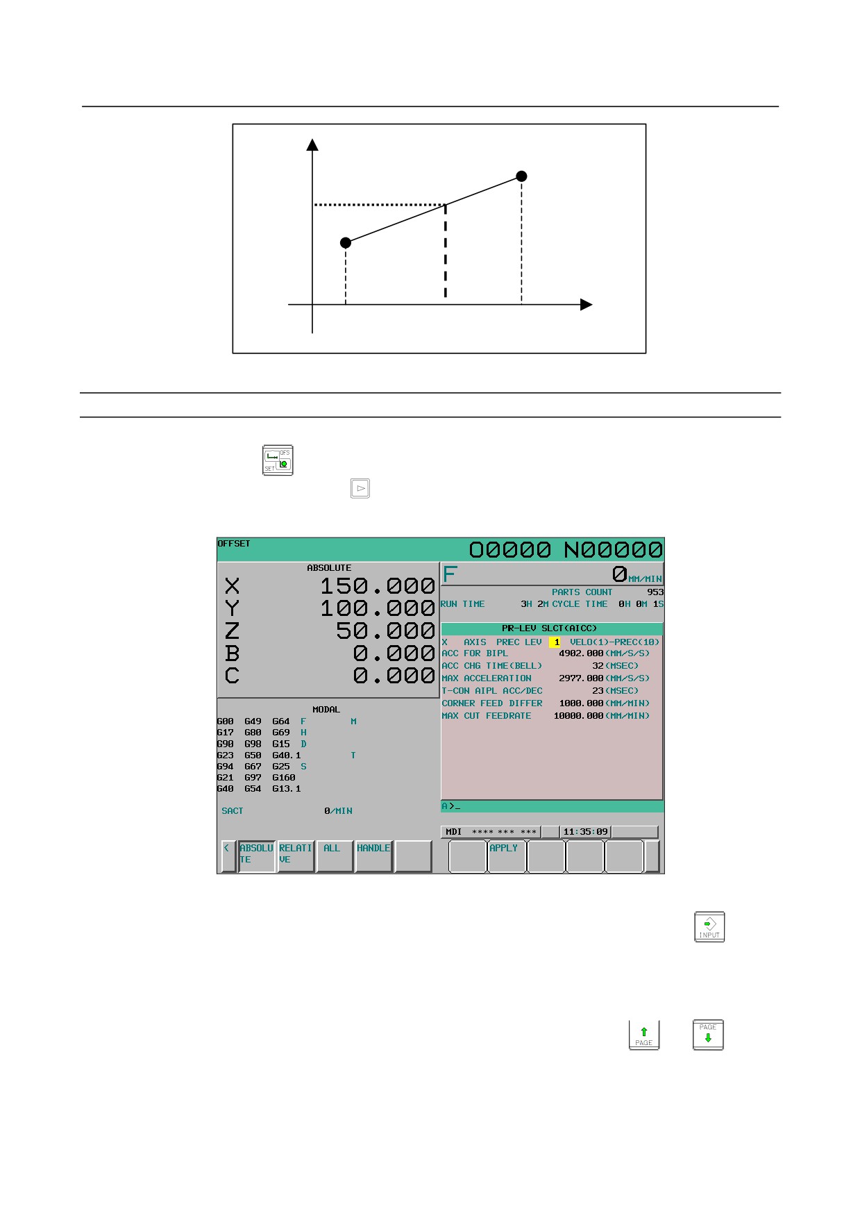
Procedure for precision level selection
1
Select the MDI mode.
2
Press function key
3
Press the continuous menu key
several times until soft key [PREC LEV] ([PR-LEV] for the
8.4-inch display unit)is displayed.
4
Press soft key [PREC LEV].
Fig. 12.3.10 (b) Precision level selection screen (10.4-inch)
5
To change the precision level, key in a desired precision level (1 to 10), then press the
key on
the MDI panel or soft key [APPLY].
6
When the precision level is changed, a RMS value is obtained from the velocity-emphasized
parameter set and precision-emphasized parameter set for parameter modification.
For the modified parameters, see the description of the machining parameter tuning.
7
If there is an axis in addition to the currently displayed axes, press page key
or
several
times to display the screen for the axis.
- 590 -
B-64304EN/02
OPERATION 12.SETTING AND DISPLAYING DATA
12.3.11 Displaying and Setting Tool Life Management Data
Displaying tool life management data on a screen enables the current status of tool life management to be
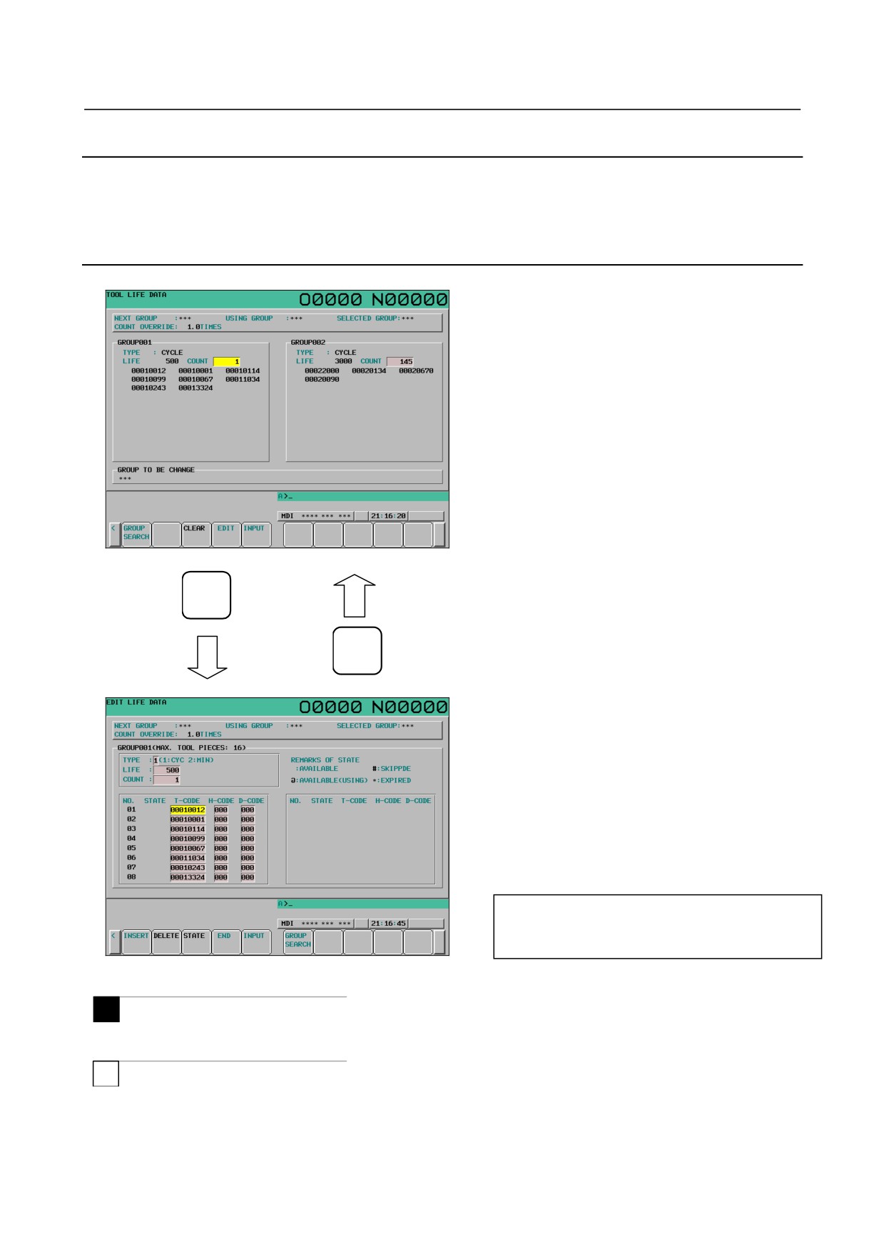
grasped. Also on the screen, tool life management data can be edited. The screen is either:
•
Tool life management (list screen) or
•
Tool life management (group editing screen)
Overview
Tool life management (list screen)
Displayed items:
- NEXT GROUP, USING GROUP, SELECTED GROUP
- COUNT OVERRIDE
- GROUP NO.
- TYPE
- LIFE, COUNT
- TOOL MANAGEMENT STATUS
- TOOL NUMBER
- GROUP TO BE CHANGE
List screen
EDIT
END
Tool life management (group editing screen)
Displayed items:
- NEXT GROUP, USING GROUP, SELECTED GROUP
- COUNT OVERRIDE
- MAX.TOOL PIECES
- TYPE
- LIFE, COUNT
- STATE
- T-CODE, H-CODE, and D-CODE
Pressing horizontal soft key [EDIT] or [END]
switches from the list screen to the group editing
screen or vice versa.
Group editing screen
M
The group editing screen always displays H and D codes.
T
The T series has the turret system to change tools and H and D codes are not used, so these codes are not
displayed.
- 591 -
12.SETTING AND DISPLAYING DATA OPERATION
B-64304EN/02
12.3.11.1 Tool life management (list screen)
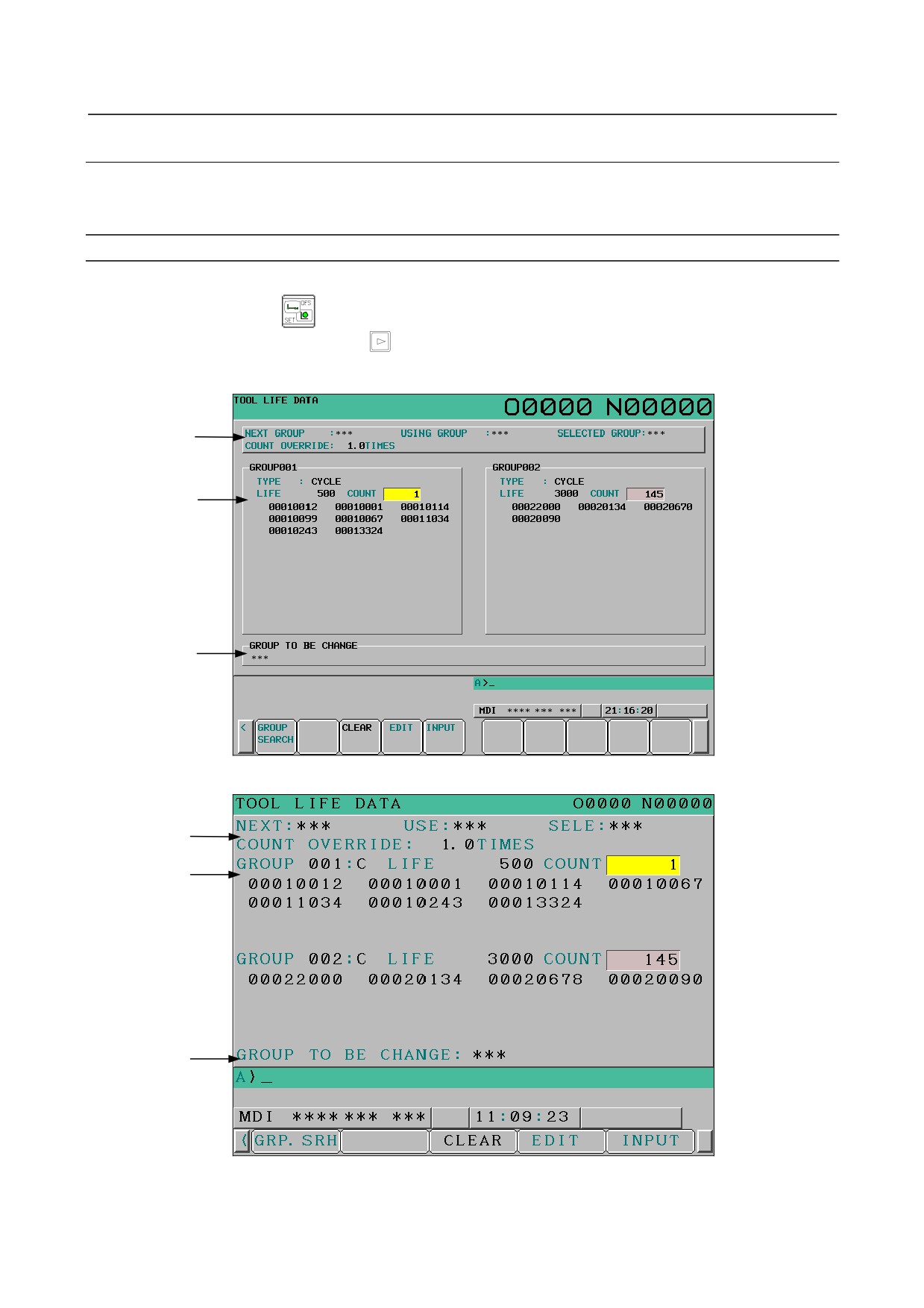
This screen can display the life management status of all tools in tool groups and whether the life of the
tool groups has expired. It also enables you to set tool life counters and clear execution data.
Displays on the list screen
Procedure
1
Press function key
2
Press the continuous menu key
several times to display soft key [TOOL LIFE] ([TOOLLF] for
the 8.4-inch display unit).
3
Press soft key [TOOL LIFE].
(A)
(B)
(C)
Fig. 12.3.11.1 (a) Displaying tool life management (list screen) (10.4-inch)
(A)
(B)
(C)
Fig. 12.3.11.1 (b) Displaying tool life management (list screen) (8.4-inch)
- 592 -
B-64304EN/02
OPERATION 12.SETTING AND DISPLAYING DATA
-
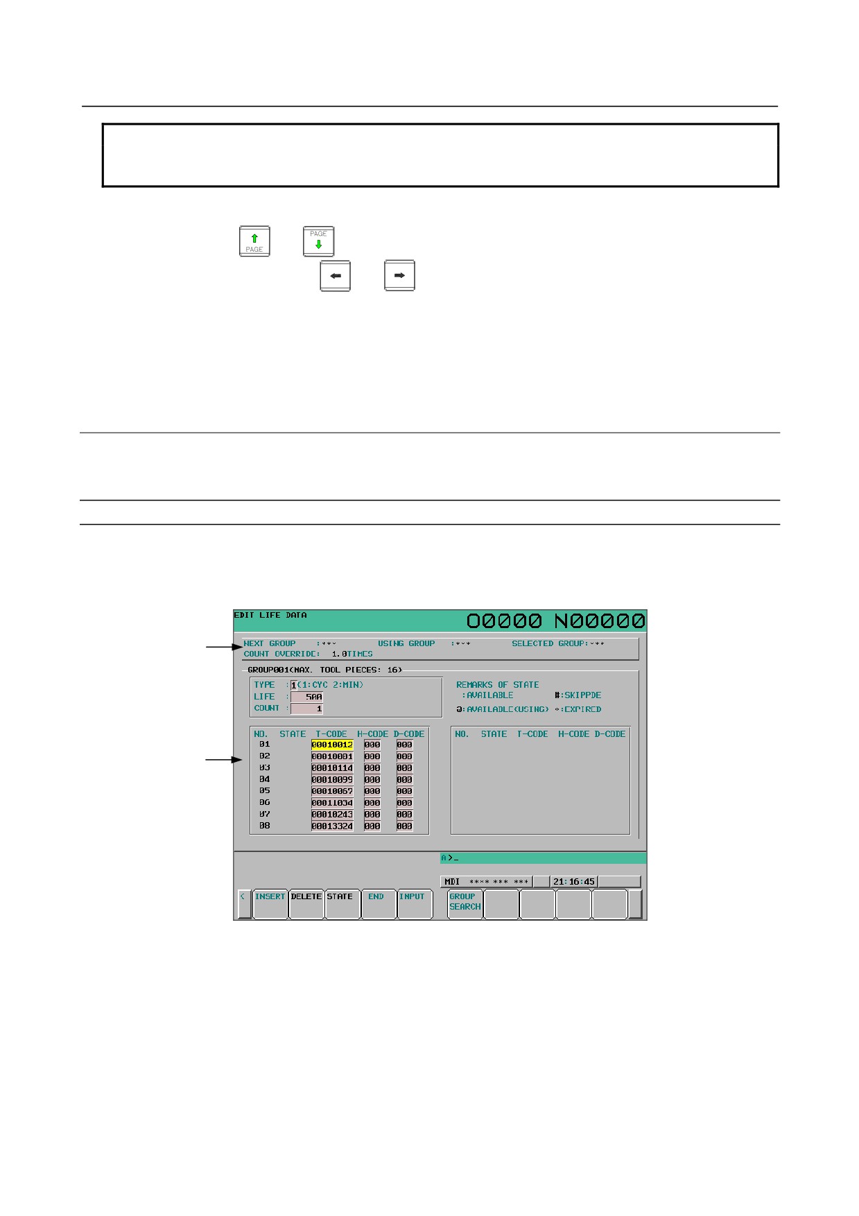
Contents of (A)
(A) displays tool group numbers and an override value. If there is no tool group to display, ***, instead
of tool group numbers, is displayed.
NEXT GROUP:
Tool group number for which life counting is started by the next M06 command.
USING GROUP:
Tool group number for which life counting is currently under way.
SELECTED GROUP:
Tool group number for which life counting is currently under way or life counting has been
performed most recently.
COUNT OVERRIDE:
The override value by which the life count (time) is multiplied is displayed if the tool life counter
override signal is enabled (bit 2 (LFV) of parameter No. 6801 = 1).
“1.0TIMES” is displayed if the tool life counter override signal is disabled (bit 2 (LFV) of parameter
No. 6801 = 0).
-
Contents of (B)
(B) displays the set life value, the current content of the tool life counter, and the registered tool numbers
(in the order they are used) for each tool group. If the life count type is specification by duration, the
measurement unit used in displaying and specifying set life values and tool life counter values is selected
according to the setting of bit 0 (FCO) of parameter No. 6805 as listed below.
Bit 0 (FCO) of parameter No. 6805
0
1
Measurement unit used in displaying and specifying set life values and tool life
1 minute
0.1 minutes
counter values
The following table lists the prefixes used with tool numbers.
Tool status
Tool in use
Tool not in use
Life remaining
@
No indication
Skip
#
#
Life expired
NOTE
1 The tool life counter indicates the count value for the tool indicated with @.
2 If bit 3 (EMD) of parameter No. 6801 = 0, a tool number remains prefixed with @
even if the life of the tool has expired until another tool is selected.
3 If bit 3 (EMD) of parameter No. 6801 =1, the following differences can occur
depending on the type of the life counter in use.
• If the life counter type is specification by duration, the prefix is changed to “*”
(life expired) as soon as the tool life expires.
• If the life counter type is specification by count, the counter is incremented by
one at the end of a program (such as M02 or M30). So, the prefix is not
changed to “*” (life expired) even if the tool life counter matches the life value.
The symbol “*” (life expired) appears when the tool life count is incremented
after the CNC is reset.
4 If bit 2 (ETE) of parameter No. 6804 = 1, the symbol “*” indicating the expiration
of the life of the last tool appears on the tool life management screen when the
life counter for the last tool of the tool group of interest matches the life value.
This way, the information about the last tool in the FOCAS2 or PMC window
indicates that the life of the tool has expired if the tool change signal TLCH
<Fn064.0> is 1.
- 593 -
12.SETTING AND DISPLAYING DATA OPERATION
B-64304EN/02
-
Contents of (C)
(C) displays tool group numbers for which a tool change signal has been issued.
If there are so many tool group numbers that all the numbers cannot be displayed, some are omitted, and
“>>” is displayed instead.
If there is no tool group number in need of change, “***” is displayed.
Setting data on the list screen
Tool life management data can be specified in the reset state (both the OP and RST signals are “0”).
However, setting bit 1 (TCI) of parameter No. 6804 to 1 enables tool life management data to be specified
even during automatic operation (the OP signal is “1”).
NOTE
As for USING GROUP or NEXT GROUP settings:
1) During automatic operation (OP signal = “1” and bit 1 (TCI) of parameter No.
6804 = 1), only the tool life counter can be changed.
2) In the reset state (OP signal = “0” and RST signal “0”), the following editing
operation stops life management because it cannot be continued.
- Clearing execution data
Procedure
-
Setting the tool life counter
The tool life counter can be set with a value, using the following methods.
Method 1
1
Place the cursor on the tool life counter for a desired tool group.
2
Enter the value from the keypad.
3
Press soft key [INPUT].
Method 2
1
Place the cursor on the tool life counter for a desired tool group.
2
Enter the value from the keypad.
3
Press
key.
-
Clearing execution data
All existing execution data for a tool group selected by the cursor can be cleared as follows:
1
Place the cursor on the tool group whose execution data you want to clear.
2
Press soft key [ERASE].
3
Press soft key [EXEC].
NOTE
Setting bit 4 (GRS) of parameter No. 6800 to 1 enables execution data for all
registered tool groups to be cleared.
-
Selecting tool groups
Tool groups can be selected using the following methods.
Method 1
1
Enter a tool group number from the keypad.
2
Press soft key [GRP.SRH].
- 594 -
B-64304EN/02
OPERATION 12.SETTING AND DISPLAYING DATA
NOTE
If arbitrary group numbers are enabled, a tool group is selected by searching for
an arbitrary group number rather than the tool group number.
Method 2
1
Press page key
or
to display desired groups.
2
Press cursor movement key
or
to move the cursor to the desired group.
-
Switching to the group editing screen
Switch to tool life management (group editing screen).
1
Move the cursor to the tool group you want to edit:
2
Press soft key [EDIT].
12.3.11.2 Tool life management (group editing screen)
On this screen, it is possible to edit tool life management data (such as tool life value, tool life counter,
and tool data) for the tool group of interest.
Displaying the group editing screen
Procedure
1
Place the cursor on the tool group you want to edit from the list screen.
2
Press soft key [(OPRT)].
3
Press soft key [EDIT].
(A)
(B)
Fig. 12.3.11.2 (a) Displaying tool life management (group editing screen) (10.4-inch)
- 595 -
12.SETTING AND DISPLAYING DATA OPERATION
B-64304EN/02
(A)
(B)
Fig. 12.3.11.2 (b) Displaying tool life management (group editing screen) (8.4-inch)
NOTE
1 If no tool is registered with a tool group, none of a life count type, a life value, and
a tool life counter value is displayed for the tool group.
2 COUNT OVERRIDE is not displayed on the group editing screen for the 8.4-inch
display unit.
-
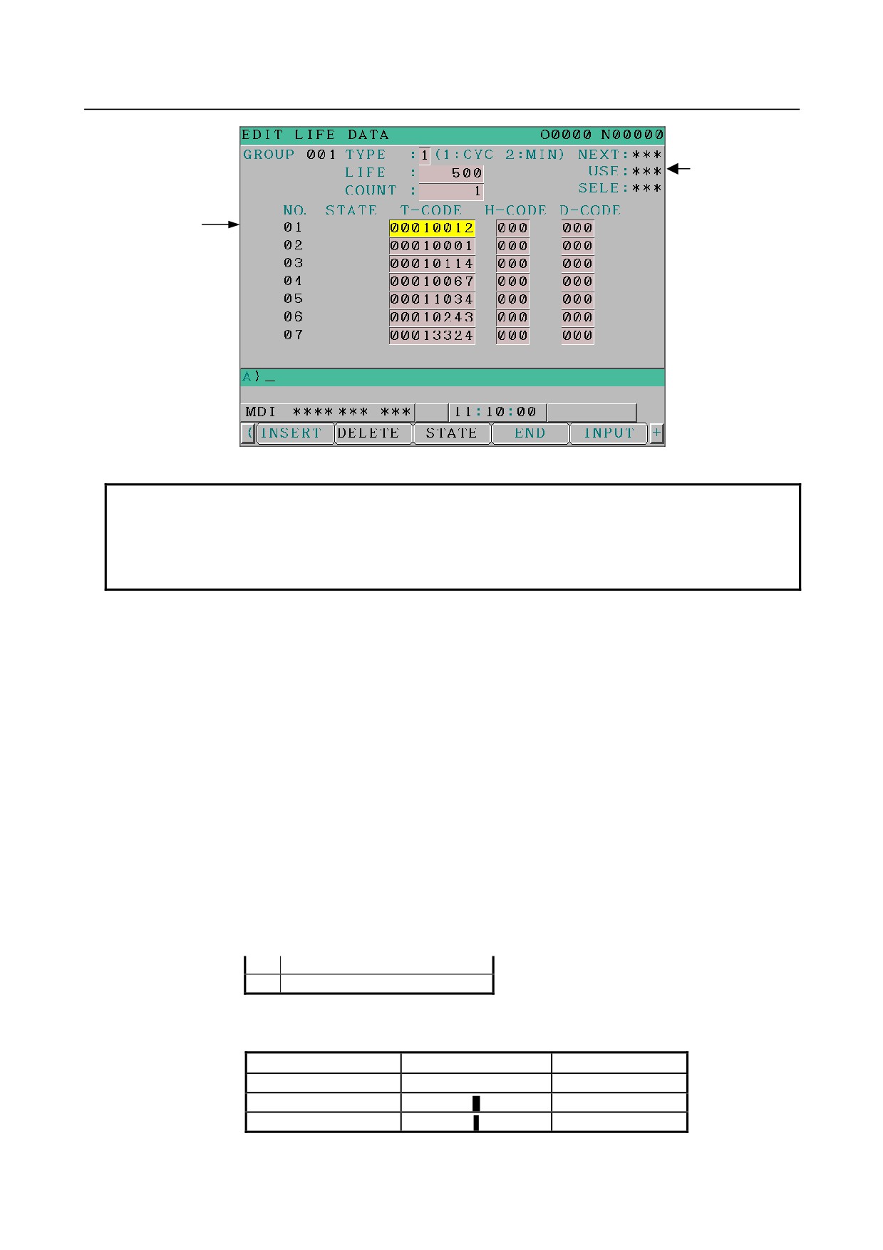
Contents of (A)
Like the counterpart of the list screen, (A) of the editing screen displays the next tool group number and
override value. If there is no appropriate tool group, *** is displayed instead.
NEXT GROUP:
Tool group for which life counting is started by the next M06 command.
USING GROUP:
Tool group number for which life counting is currently under way.
SELECTED GROUP:
Tool group number for which life counting is currently under way or life counting has been
performed most recently.
COUNT OVERRIDE:
The override value by which the life count (time) is multiplied is displayed if the tool life counter
override signal is enabled (bit 2 (LFV) of parameter No. 6801 = 1).
“1.0TIMES” is displayed if the tool life counter override signal is disabled (bit 2 (LFV) of parameter
No. 6801 = 0).
-
Contents of (B)
(B) details tool life management data related to a selected tool group as follows:
TYPE
:
1
Specification by count
2
Specification by duration
LIFE
:
Tool life value
COUNT
:
Tool life counter
STATE
:
Tool status
Tool in use
Tool not in use
Life remaining
@
No indication
Skip
#
#
Life expired
*
*
T-CODE
:
Tool number
- 596 -
B-64304EN/02
OPERATION 12.SETTING AND DISPLAYING DATA
M
H-CODE
: Tool length compensation specification code
D-CODE
: Cutter compensation specification code
T
H-CODE
: No display.
D-CODE
: No display.
NOTE
1 The tool life counter indicates the count value for the tool indicated with @.
2 If bit 3 (EMD) of parameter No. 6801 = 0, a tool number remains prefixed with @
even if the life of the tool has expired until another tool is selected.
3 If bit 3 (EMD) of parameter No. 6801 = 1, the following differences can occur
depending on the type of the life counter in use.
• If the life counter type is specification by duration, the prefix is changed to “*”
(life expired) as soon as the tool life expires.
• If the life counter type is specification by count, the counter is incremented by
one at the end of a program (such as M02 or M30). So, the prefix is not
changed to “*” (life expired) even if the tool life counter matches the life value.
The symbol “*” (life expired) appears when the tool life count is incremented
after the CNC is reset.
4 If bit 2 (ETE) of parameter No. 6804 = 1, the symbol “*” indicating the expiration
of the life of the last tool appears on the tool life management screen when the
life counter for the last tool of the tool group of interest matches the life value.
This way, the information about the last tool in the FOCAS2 or PMC window
indicates that the life of the tool has expired if the tool change signal TLCH
<Fn064.0> is 1.
Setting data on the group editing screen
Tool life management data can be specified in the reset state (both the OP and RST signals are “0”).
However, setting bit 1 (TCI) of parameter No. 6804 to “1” enables tool life management data to be
specified even during automatic operation (the OP signal is “1”).
The available editing operations are listed below.
M
Items that can be edited
Mode
Setting a life count type, life value, tool life counter, and tool data (T code, H code, and D code)
All modes
Adding tool numbers (T code)
MDI
Deleting all tool group data at a time
MDI
Deleting tool data (status, T code, H code, and D code)
MDI
Selecting tool skip
MDI
Specifying to clear tool data (life re-set)
MDI
T
Items that can be edited
Mode
Setting a life count type, life value, tool life counter, and tool data (T code)
All modes
Adding tool numbers (T code)
MDI
Deleting all tool group data at a time
MDI
Deleting tool data (status and T code)
MDI
Selecting tool skip
MDI
- 597 -
12.SETTING AND DISPLAYING DATA OPERATION
B-64304EN/02
Items that can be edited
Mode
Specifying to clear tool data (life re-set)
MDI
If no tool is registered with a tool group, none of a life count type, a tool life value, and a tool life counter
value can be set for the tool group. First of all, add a tool number (T code).
NOTE
1 As for USING GROUP or NEXT GROUP editing:
<1> During automatic operation (OP signal = “1” and bit 1 (TCI) of parameter
No. 6804 = 1), only the tool life counter can be changed.
<2> In the reset state (OP signal = “0” and RST signal “0”), the following editing
operation stops life management because it cannot be continued.
- Adding tool numbers (T code)
- Deleting all tool group data at a time
- Deleting tool data (status, T code, H code, and D code)
2 The following editing operations may set the tool change signal to ”1”.
- Selecting tool skip for the last tool.
- Deleting tool numbers, resulting in any tool other than those whose life has
expired or who have been skipped being not found in the tool group of interest.
3 The following editing operations may reset the tool change signal to ”0”.
- Adding tool numbers, leading to tools whose life has not expired being set in
the tool group of interest.
- Selecting tool clear.
Procedure
- Setting a life count type, tool life value, tool life counter, and tool data
Setting a life count type, tool life value, tool life counter, and tool data
Method 1
1
Place the cursor on the desired item.
2
Enter a value from the keypad.
3
Press soft key [INPUT].
Method 2
1
Place the cursor on the desired item.
2
Enter a value from the keypad.
3
Press
NOTE
1 Changing a tool life value or tool life counter does not affect the tool status or tool
change signal.
2 Changing a life count type causes the tool life value and too life counter to be
reset to 0.
-
Adding tool numbers
Tool numbers can be added to a tool group as follows:
1
Select the MDI mode.
2
Place the cursor on the tool data (T code, H code, or D code) just before a tool number to be added.
3
Enter the tool number from the key pad.
4
Press soft key [INSERT].
- 598 -
B-64304EN/02
OPERATION 12.SETTING AND DISPLAYING DATA
(Example)
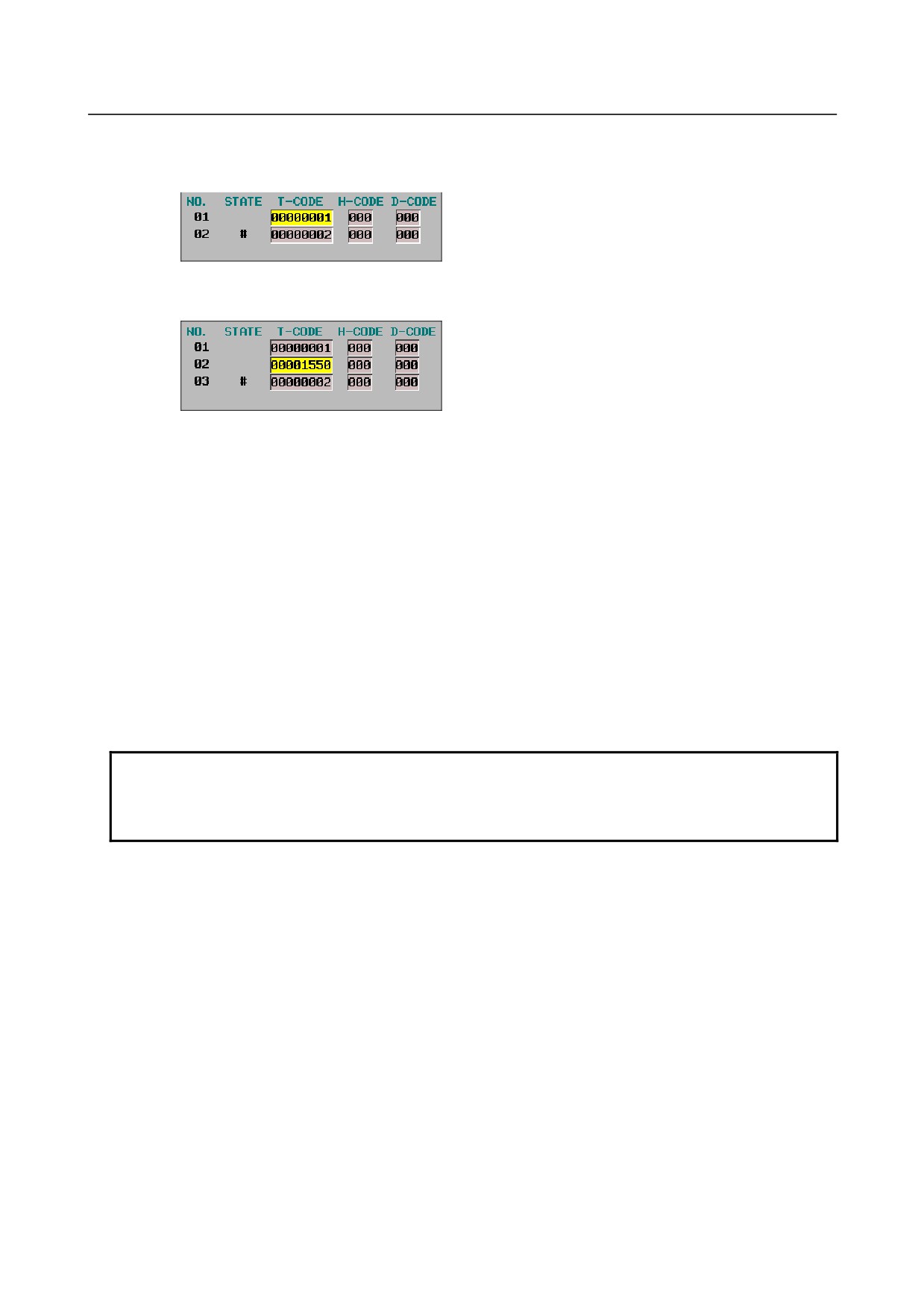
Adding tool number 1550 between numbers 1 and 2 (for the M series)
1
Move the cursor to the data for number 1, enter “1550”, and press [INSERT].
2
The entered T code 1550 is inserted in the position of number 2. The H and D codes are reset
to 0.
-
Deleting all tool group data at a time
All tool group data can be deleted at a time as follows:
1
Select the MDI mode.
2
Place the cursor on the tool data (T code, H code, or D code) just Select the tool group from which
all tool data you want to delete at a time.
3
Press soft key [DELETE].
4
Press soft key [GROUP].
5
Press soft key [EXEC].
-
Deleting tool data
Tool data can be deleted from a tool group as follows:
1
Select the MDI mode.
2
Place the cursor on the tool data (T code, H code, or D code) you want to delete.
3
Press soft key [DELETE].
4
Press soft key [<CURS>].
NOTE
1 Deleting all tools from a tool group is equivalent to deleting the tool group itself.
2 Deleting a tool indicated with @ (in use) results in @ being moved to the previous
tool whose life has expired or which has been skipped.
-
Selecting tool skip
Tool data can be placed in a skip state as follows:
1
Select the MDI mode.
2
Place the cursor on the tool data (T code, H code, or D code) for a tool you want to skip.
3
Press soft key [STATE].
4
Press soft key [SKIP].
-
Specifying to clear tool data (life re-set)
Tool data state can be cleared as follows:
1
Select the MDI mode.
2
Place the cursor on the tool data (T code, H code, or D code) for a tool you want to clear.
3
Press soft key [STATE].
4
Press soft key [CLEAR].
- 599 -
12.SETTING AND DISPLAYING DATA OPERATION
B-64304EN/02
-
Selecting a tool group
A tool group can be selected as follows:
Method 1
1
Enter a tool group number from the keypad.
2
Press soft key ['GRP.SRH].
-
Switching to the list screen
The tool life management (list screen) can be resumed as follows:
1
Press soft key [END].
12.3.12 Displaying and Setting Pattern Data Inputs
Described below are a method for displaying machining menus (pattern menus) created by machine tool
builders and a method for setting them. The descriptions are based on an example. For actual pattern
menus and pattern data, refer to manuals released by respective machine tool builders.
Displaying pattern data and pattern menus
Given below is a procedure for displaying pattern menus.
1
Press function key
2
Press the continuous menu key
3
Press soft key [PATTERN MENU] ([MENU] for the 8.4-inch display unit).
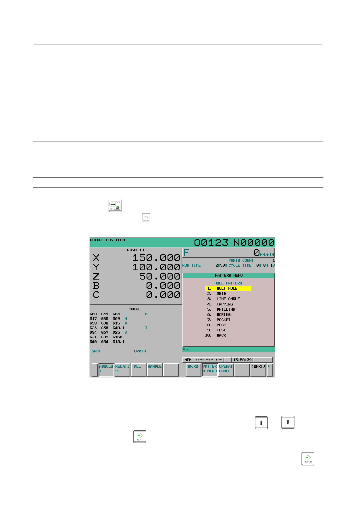
The pattern menu screen shown below appears.
Fig. 12.3.12 (a) Pattern menu screen (10.4-inch)
On this screen, a pattern to be used can be selected.
The following two methods can be used to select patterns.
• Using the cursor
Move the cursor to a pattern name you want to select, using cursor key
or
, and then
press soft key [SELECT] or
• Specifying a pattern number
Enter a number displayed at the left side of a pattern name, and press soft key [SELECT] or
- 600 -
B-64304EN/02
OPERATION 12.SETTING AND DISPLAYING DATA
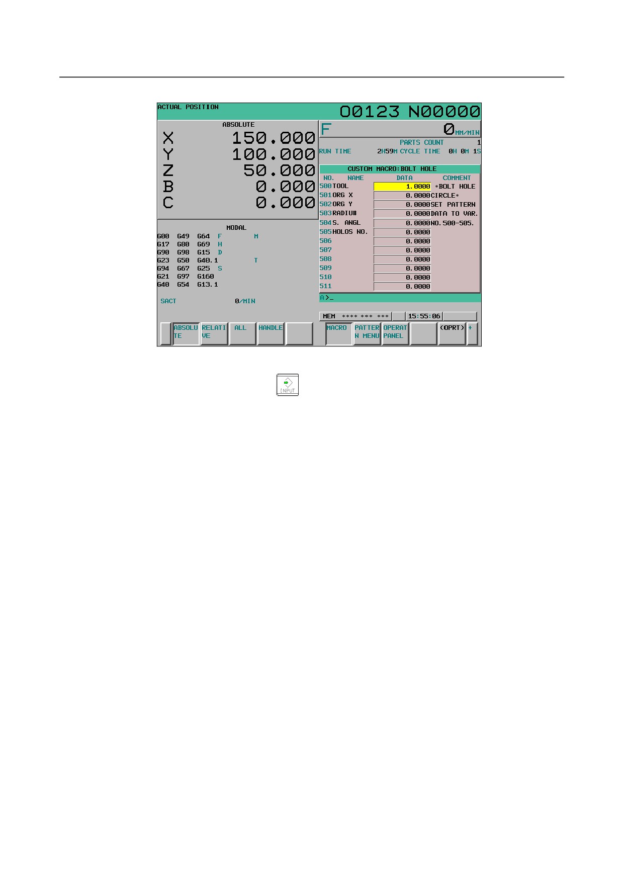
The custom macro screen (pattern data screen) shown below appears.
Fig. 12.3.12 (b) Custom macro screen (pattern data) (10.4-inch)
Enter the necessary pattern data, and press
After entering all necessary data, select the MEMORY mode and press the cycle start button.
Machining begins.
Explanation
-
Explanations about the pattern menu screen
HOLE PATTERN
An arbitrary character string consisting of 12 or less characters can be displayed as a menu title.
BOLT HOLE
An arbitrary character string consisting of 10 or less characters can be displayed as a pattern name.
Machine tool builders should program menu title and pattern name character strings, using custom macros,
and save them in program memory.
For details on this program, see II-16.
-
Explanations about the custom macro screen (pattern data screen)
BOLT HOLE
An arbitrary character string consisting of 12 or less characters can be displayed as a pattern data title.
TOOL.
An arbitrary character string consisting of 10or less characters can be displayed as a variable name.
*BOLT HOLE CIRCLE*
Up to 12 lines (10.4-inch display unit) or 8 lines (8.4-inch display unit) of comments can be displayed by
a comment statement with one block assumed to be 12 characters and with one block to be one line.
Machine tool builders should program variable name and comment text character strings, using custom
macros, and save them in program memory.
For details on this program, see II-16.
- 601 -

12.SETTING AND DISPLAYING DATA OPERATION
B-64304EN/02
12.4 SCREENS DISPLAYED BY FUNCTION KEY
When the CNC and machine are connected, parameters must be set to determine the specifications and
functions of the machine in order to fully utilize the characteristics of the servo motor or other parts.
This chapter describes how to set parameters on the MDI panel. Parameters can also be set with external
input/output devices such as the memory card (see III-8).
In addition, pitch error compensation data used for improving the precision in positioning with the ball
screw on the machine can be set or displayed by the operations under function key
Section
12.4, "SCREENS DISPLAYED BY FUNCTION KEY
", consists of the following
subsections:
12.4.1 Displaying and Setting Parameters
602
12.4.2 Displaying and Setting Pitch Error Compensation Data
604
12.4.3 Servo Setting
607
12.4.4 Servo Tuning
610
12.4.5 Spindle Setting
610
12.4.6 Spindle Tuning
613
12.4.7 Spindle Monitor
614
12.4.8 Color Setting Screen
615
12.4.9 Machining Parameter Tuning
617
12.4.10 Parameter Setting Support Screen
622
12.4.11 Periodic Maintenance Screen
649
12.4.12 System Configuration Screen
655
12.4.13 Overview of the History Function
658
See III-7 for the diagnosis screens displayed by pressing function key
Screens of a 7.2/8.4/10.4-inch display unit
12.4.1 Displaying and Setting Parameters
When the CNC and machine are connected, parameters are set to determine the specifications and
functions of the machine in order to fully utilize the characteristics of the servo motor. The setting of
parameters depends on the machine. Refer to the parameter list prepared by the machine tool builder.
Normally, the user need not change parameter setting.
Procedure for displaying and setting parameters
Procedure
1
Set 1 for PARAMETER WRITE to enable writing. See the procedure for enabling/displaying
parameter writing described below.
2
Press function key
3
Press chapter selection soft key [PARAM] to display the parameter screen.
- 602 -

B-64304EN/02
OPERATION 12.SETTING AND DISPLAYING DATA
Fig. 12.4.1 (a) PARAMETER screen (10.4-inch)
4
Move the cursor to the parameter number to be set or displayed in either of the following ways:
•
Enter the parameter number and press soft key [NO.SRH] .
•
Move the cursor to the parameter number using the page keys,
and
, and cursor
keys,
,
,
, and
5 To set the parameter, enter a new value with numeric keys and press soft key [INPUT] in MDI mode.
The parameter is set to the entered value and the value is displayed.
6
Set 0 for PARAMETER WRITE to disable writing.
Procedure for enabling/displaying parameter writing
Procedure
1
Select the MDI mode or enter state emergency stop.
2
Press function key
3
Press soft key [SETTING] to display the setting screen.
- 603 -
12.SETTING AND DISPLAYING DATA OPERATION
B-64304EN/02
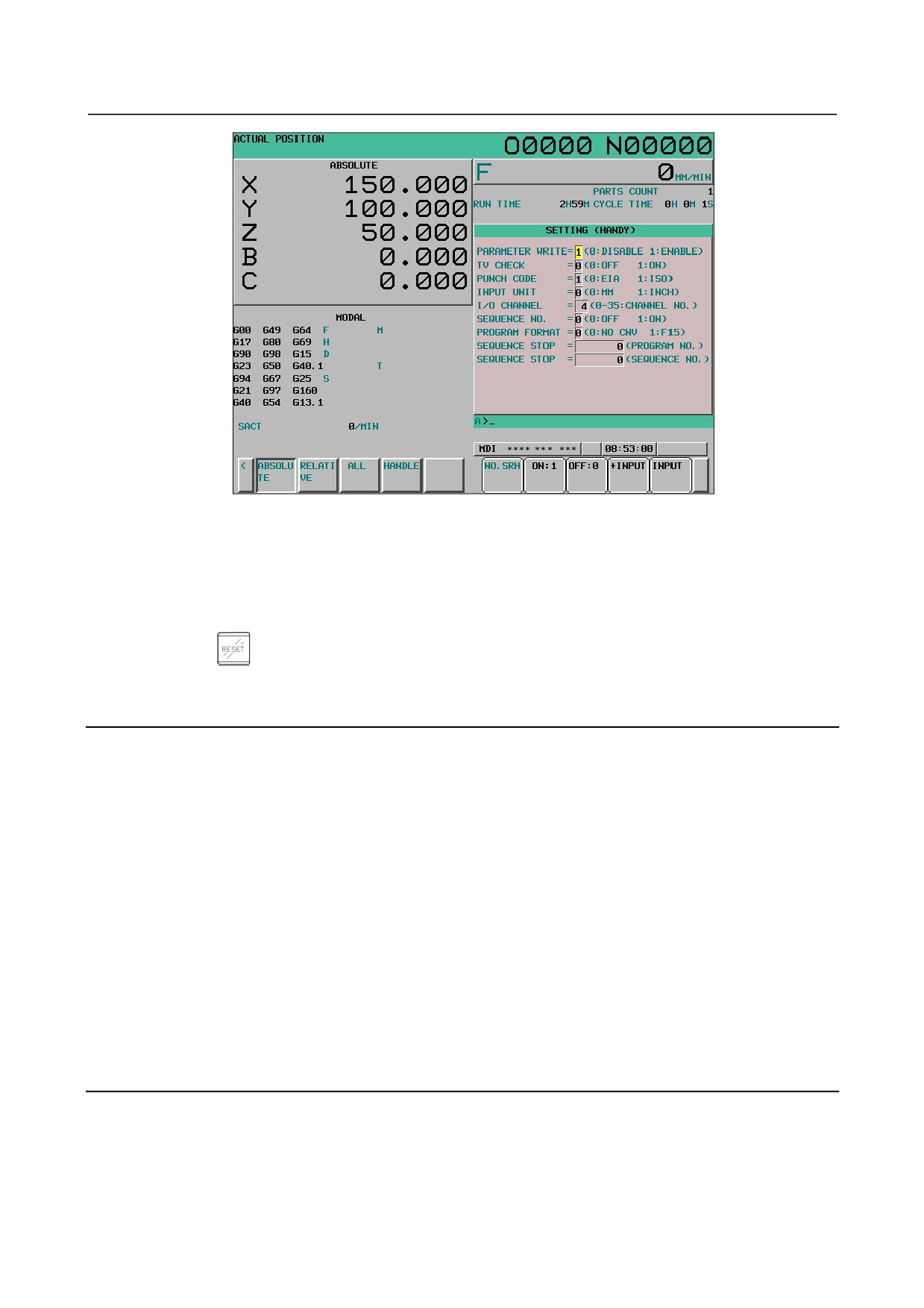
Fig. 12.4.1 (b) SETTING screen (10.4-inch)
4
Move the cursor to PARAMETER WRITE using cursor keys.
5
Press soft key [(OPRT)], then press [ON:1] to enable parameter writing.
At this time, the CNC enters the alarm state SW0100.
6
After setting parameters, return to the setting screen. Move the cursor to PARAMETER WRITE and
press soft key [(OPRT)] , then press [OFF:0].
7
Press the
key to release the alarm condition.
When an alarm PW0000 occurred, however, it is not released unless the power is turned off and
back on.
Explanation
-
Setting parameters with external input/output devices
See III-8 for setting parameters with external input/output devices such as the memory card.
-
Parameters that require turning off the power
Some parameters are not effective until the power is turned off and on again after they are set. Setting
such parameters causes alarm PW0000. In this case, turn off the power, then turn it on again.
-
Parameter list
Refer to the Parameter Manual (B-64310EN) for the parameter list.
-
Setting data
Some parameters can be set on the setting screen if the parameter list indicates "Setting entry is
acceptable". Setting 1 for PARAMETER WRITE is not necessary when these parameters are set on the
setting screen.
12.4.2 Displaying and Setting Pitch Error Compensation Data
If pitch error compensation data is specified, pitch errors of each axis can be compensated in detection
unit per axis.
Pitch error compensation data is set for each compensation point at the intervals specified for each axis.
The origin of compensation is the reference position to which the tool is returned.
- 604 -
B-64304EN/02
OPERATION 12.SETTING AND DISPLAYING DATA
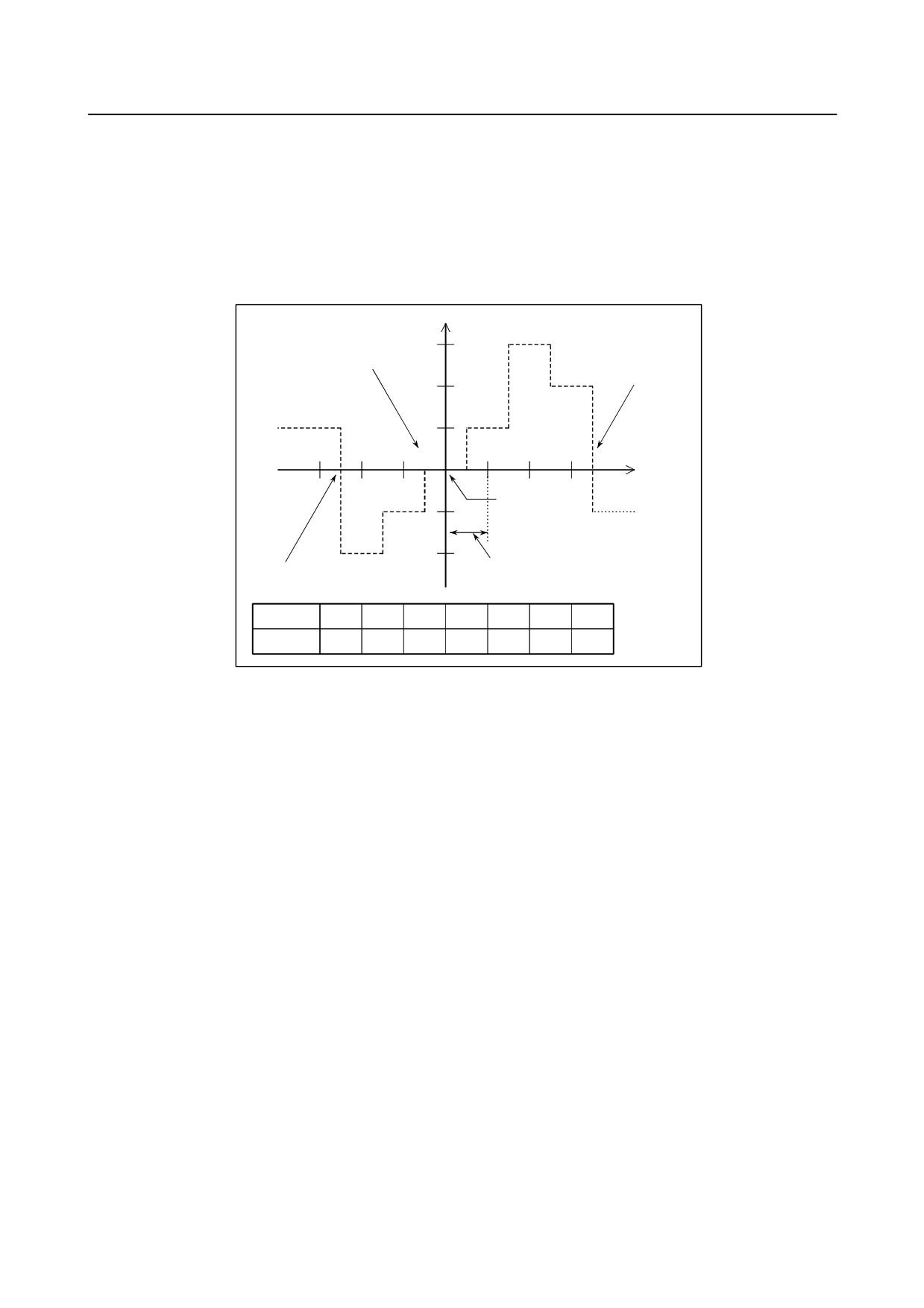
The pitch error compensation data is set according to the characteristics of the machine connected to the
NC. The content of this data varies according to the machine model. If it is changed, the machine
accuracy is reduced. In principle, the end user must not alter this data.
Pitch error compensation data can be set with external devices such as the memory card (see Chapter
III-8). Compensation data can also be written directly with the MDI panel.
The following parameters must be set for pitch error compensation. Set the pitch error compensation
value for each pitch error compensation point number set by these parameters.
In the following example, 33 is set for the pitch error compensation point at the reference position.
Pitch error compensation value (absolute value)
Compensation number
Compensation number
parameter for the
parameter for the reference
3
compensation point having
position (No. 3620)
the largest value (No.
2
3622)
1
31
32
33
34
35
36
37
Reference position
-1
Compensation magnification
parameter (No. 3623)
-2
Compensation number parameter for
Compensation
the compensation point having the
interval parameter
smallest value (No. 3621)
(No. 3624)
Compensation
position number
31
3
3
3
3
3
3
Compensation
value to be set
-3
+1
+1
+1
+2
-1
-3
•
Number of the pitch error compensation point at the reference position (for each axis): Parameter No.
3620
•
Number of the pitch error compensation point having the smallest value (for each axis): Parameter
No. 3621
•
Number of the pitch error compensation point having the largest value (for each axis): Parameter No.
3622
•
Pitch error compensation magnification (for each axis): Parameter No. 3623
•
Interval of the pitch error compensation points (for each axis): Parameter No. 3624
•
Travel distance per revolution of pitch error compensation of the rotary axis type (for each axis):
Parameter No. 3625
-
Bi-directional pitch error compensation
The bi-directional pitch error compensation function allows independent pitch error compensation in
different travel directions.
(When the movement is reversed, compensation is automatically carried out
as in a backlash.)
To use this function, specify pitch error compensation for each travel direction, that is, separately for the
positive and negative directions of a movement.
When using bi-directional pitch error compensation (setting bit 0 (BDPx) of parameter No. 3605 to 1),
specify the following parameters in addition to the pitch error compensation parameter.
• Number of the pitch error compensation point at the negative end (for travel in the positive direction,
for each axis): Parameter No. 3621
• Number of the pitch error compensation point at the positive end (for travel in the positive direction,
for each axis): Parameter No. 3622
• Number of the pitch error compensation point at the negative end (for travel in the negative direction,
for each axis): Parameter No. 3626
- 605 -