FANUC Series 0i-MODEL D, Series 0i Mate-MODEL D. OPERATOR'S MANUAL - page 23
12.SETTING AND DISPLAYING DATA OPERATION
B-64304EN/02
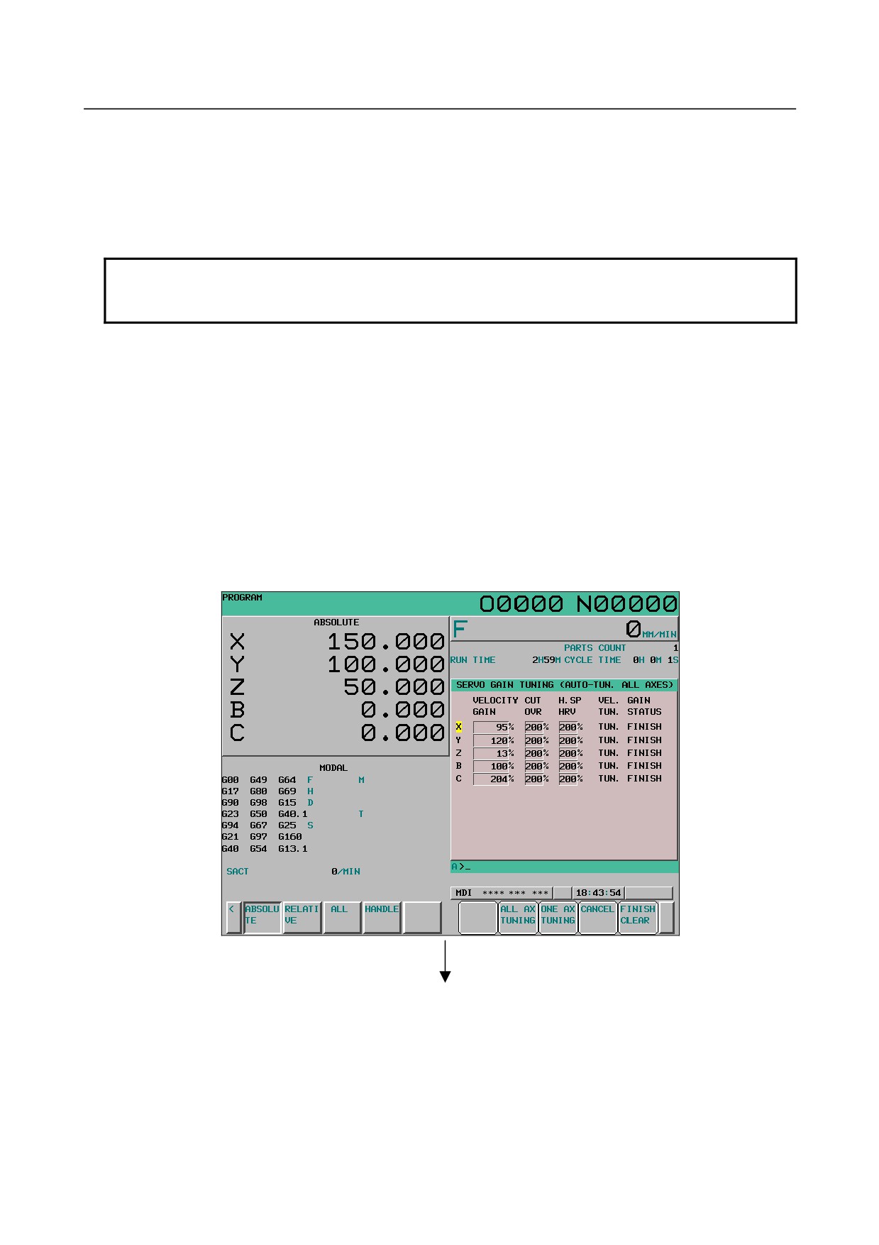
For example, in the conditions shown in the above figure, automatic tuning starts with the X-axis and,
when the X-axis is completed, the cursor moves to the Z-axis; then automatic tuning stops. If soft key
[ONE AX TUNING] is pressed again at this time, the Z-axis is subjected to automatic tuning.
The cursor keys are disabled when any axis is being subjected to automatic tuning and, if automatic
tuning is completed, the cursor keys are enabled. When automatic tuning of all axes is completed, the
cursor returns to the first axis.
NOTE
Even when the cursor positions at other than the first axis, automatic tuning
starts with the first axis.
- Aborting automatic tuning
When no axis in a path is being subjected to automatic tuning, soft key [CANCEL] is displayed. When
soft key [CANCEL] is pressed, the servo gain tuning screen (automatic tuning screen) is displayed again
without automatic tuning being started.
- Clearing tuning completion
When no axis in a path is not being subjected to automatic tuning, soft key [FINISH CLEAR] ([FIN.CL]
for the 8.4-inch display unit) is displayed.
When [FINISH CLEAR] is pressed during all axis tuning, the VEL. GAIN TUN. STATUS indication of
the axes in the tuning completion state is cleared to the incompletion state (blank) as shown in the right
half of the lower figure. However, the set VELOCITY GAIN, CUT DVR, and H. SP HRV are not
cleared.
Cleared
- 636 -
B-64304EN/02
OPERATION 12.SETTING AND DISPLAYING DATA
NOTE
A clear operation in the tuning completion state does not clear the VEL. GAIN
TUN. STATUS indication of the axis in the INIT. ERR state.
To clear the INIT. ERR state, change the setting of VELOCITY GAIN, CUT DVR,
or H. SP HRV on the manual tuning screen.
- Select axis tuning
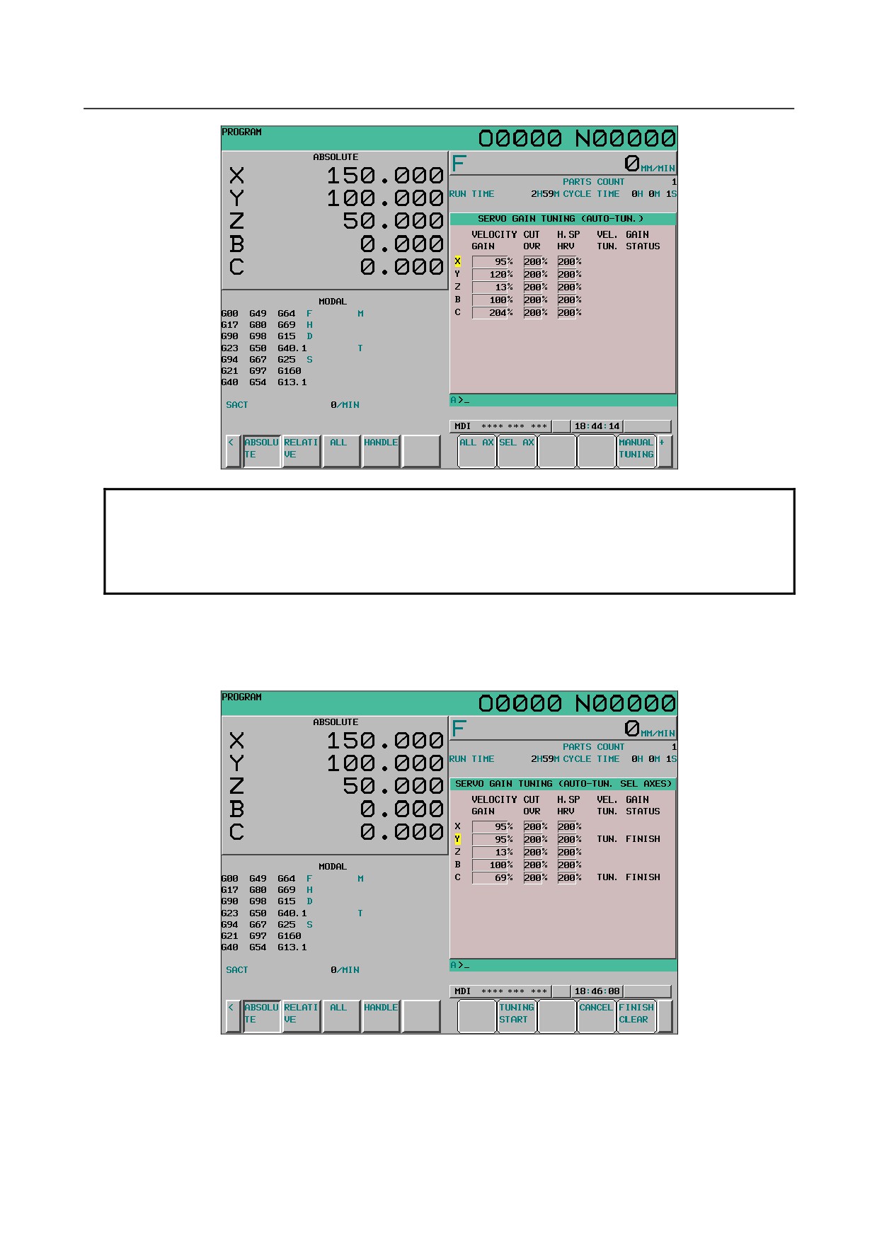
When soft key [SEL AX] is pressed on the automatic tuning screen, the following soft keys are displayed
and the SERVO GAIN TUNING (AUTO-TUN SEL AXES) is indicated on the title bar of the screen.
Fig. 12.4.10.7 (e) Automatic tuning screen (select axis tuning) (10.4-inch)
- Selected axis tuning
When no axis in a path is being subjected to automatic tuning, soft key [TUNING START] ([START] for
the 8.4-inch display unit) is displayed.
- 637 -
12.SETTING AND DISPLAYING DATA OPERATION
B-64304EN/02
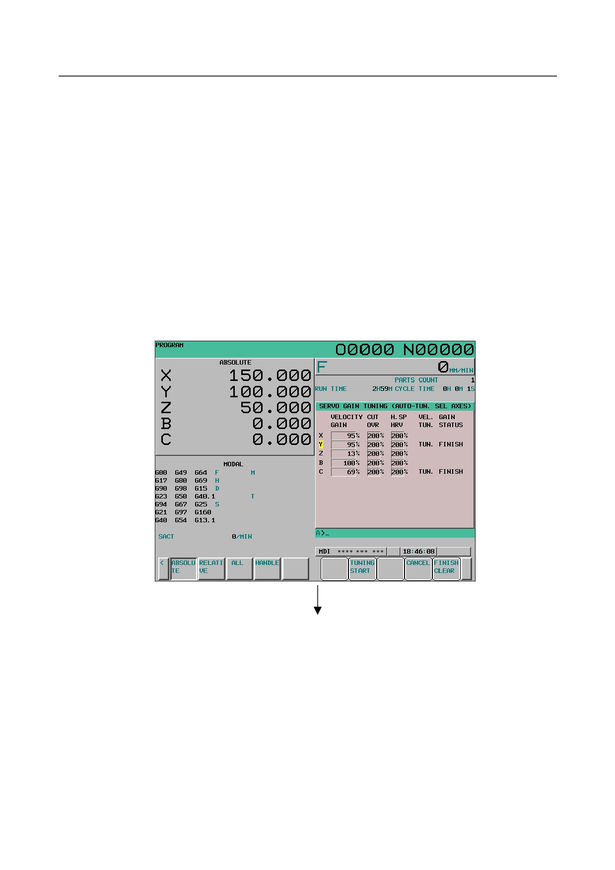
When soft key [TUNING START] is pressed during selected axis tuning, the axis selected by the cursor
is subjected to automatic tuning. At this time, automatic tuning is performed again regardless of the
tuning status of the selected axis. For example, in the state shown above, automatic tuning of the Y-axis
was finished, but automatic tuning is performed again.
The cursor keys are disabled during selected axis tuning. Upon completion of automatic tuning, the
cursor keys are enabled.
- Aborting automatic tuning
When no axis in a path is being subjected to automatic tuning, soft key [CANCEL] is displayed. When
soft key [CANCEL] is pressed, the servo gain tuning screen (automatic tuning screen) is displayed again
without automatic tuning being started.
- Clearing the automatic tuning status
When no axis in a path is not being subjected to automatic tuning, soft key [FINISH CLEAR] ([FIN.CL]
for the 8.4-inch display unit) is displayed. When [FINISH CLEAR] is pressed during selected axis
tuning, if the axis selected by the cursor is in the tuning completion state, the indication of VEL. GAIN
TUN. STATUS is cleared to the incompletion state (blank). However, the set VELOCITY GAIN, CUT
DVR, and H. SP HRV are not cleared.
Cleared
- 638 -
B-64304EN/02
OPERATION 12.SETTING AND DISPLAYING DATA
NOTE
A clear operation in the tuning completion state does not clear the VEL. GAIN
TUN. STATUS indication of the axis in the INIT. ERR state.
To clear the INIT. ERR state, change the setting of VELOCITY GAIN, CUT DVR,
or H. SP HRV on the manual tuning screen.
- Forcibly stopping automatic tuning
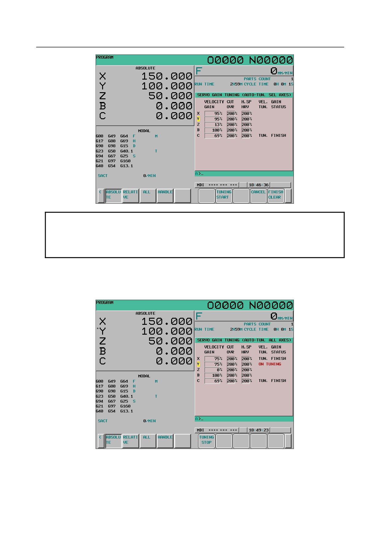
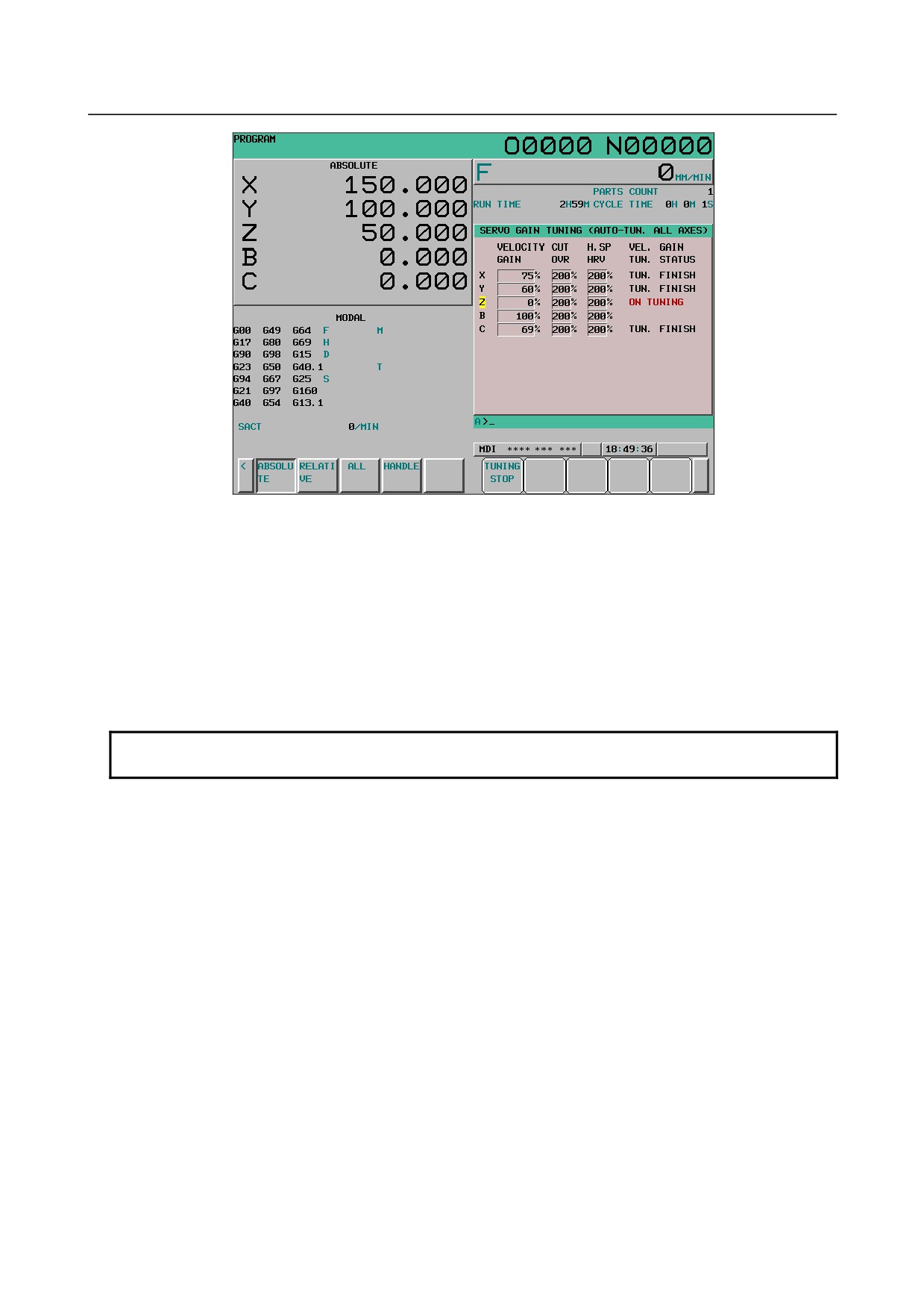
When one axis in a path is being subjected to automatic tuning, the following screen and soft key
[TUNING STOP] ([STOP] for the 8.4-inch display unit) is displayed.
Fig. 12.4.10.7 (f) All axes being tuned (10.4-inch)
- 639 -
12.SETTING AND DISPLAYING DATA OPERATION
B-64304EN/02
Fig. 12.4.10.7 (g) Selected axis being tuned (10.4-inch)
When soft key [TUNING STOP] is pressed at this time, automatic tuning is forcibly stopped even during
automatic tuning. It is also possible to forcibly stop automatic tuning by pressing the RESET key or set
the CNC in the emergency stop state.
The VELOCITY GAIN, CUT DVR, and H. SP HRV settings of the axis for which automatic tuning was
stopped midway are returned to the settings before automatic tuning. For all axis tuning, the
VELOCITY GAIN, CUT DVR, and H. SP HRV settings of the axis for which automatic tuning was
completed remain at the values set during automatic tuning.
However, automatic tuning is stopped midway, so the indication of VEL. GAIN TUN. STATUS becomes
blank (incompletion).
NOTE
Automatic tuning can be stopped regardless of the cursor position.
- Servo gain manual tuning screen
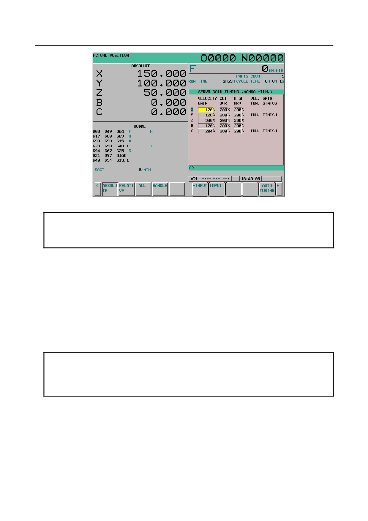
On the manual tuning screen, it is possible to directly enter a value in VELOCITY GAIN, CUT DVR, and
H. SP HRV of an arbitrary axis with MDI keys. This operation is called manual tuning.
- Displaying the manual tuning screen
When soft key [MANUAL TUNING] ([MANUAL] for the 8.4-inch display unit) is pressed on the
automatic tuning screen, the manual tuning screen is displayed.
- 640 -
B-64304EN/02
OPERATION 12.SETTING AND DISPLAYING DATA
Fig. 12.4.10.7 (h) Servo gain tuning screen (manual tuning screen) (10.4-inch)
NOTE
If any axis is being subjected to automatic tuning, [MANUAL TUNING] is not
displayed on the automatic tuning screen. Accordingly, the manual tuning
screen cannot be displayed during automatic tuning.
- Setting parameters
Move the cursor to the desired item of the desired axis and enter a value directly with MDI keys.
When soft key [+INPUT], soft key [INPUT], or MDI key [INPUT] is pressed, the value is set.
Soft key [+ INPUT]
The value already set plus the value entered by MDI keys are set.
Example) When the current setting is 500 and the value entered by MDI keys is 50
The value to be entered is 550.
MDI key [INPUT], soft key [INPUT]
The value entered by the MDI key is set as is.
NOTE
During input with soft key [INPUT], if a value preceded by the + symbol such as
"+1" is input, a warning saying "FORMAT ERROR" is issued.
If a value falling outside the set range is input, the value is changed so as to fall
within the range.
- Automatic tuning state
TUN. FINISH is indicated under VEL. GAIN TUN. STATUS for the axis that was subjected to automatic
tuning and INIT. ERR is indicated for the axis for which the initial status is illegal. If any of
VELOCITY GAIN, CUT OVR, and H.SP HRV of the axis that was subjected to automatic tuning or the
axis for which the initial status is illegal is set to a value, the VEL. GAIN TUN. STATUS indication is
cleared to become blank (incompletion state).
- Switching to the automatic tuning screen
To return to the automatic tuning screen from the manual tuning screen, press soft key [AUTO TUNING]
([AUTO] for the 8.4-inch screen) on the manual tuning screen. The automatic tuning screen appears.
- 641 -
12.SETTING AND DISPLAYING DATA OPERATION
B-64304EN/02
- Caution
Reset
If the RESET key is pressed or external reset signal ERS<Gn008.7> or reset & rewind signal
RRW<Gn008.6> is input during automatic tuning, automatic tuning is stopped.
VEL. GAIN TUN. STATUS "INIT. ERR"
When INIT. ERR is indicated under VEL. GAIN TUN. STATUS, automatic tuning cannot be performed
because the setting of VELOCITY GAIN is illegal.
Change the setting of VELOCITY GAIN.
Changing parameters
If the setting of VELOCITY GAIN, CUT OVR, or H.SP HRV of the axis being subjected to automatic
tuning is changed on the parameter screen or by an external application, automatic tuning is stopped. At
this time, automatic tuning is incomplete and VEL. GAIN TUN. STATUS becomes blank.
Re-execution of automatic tuning
To re-execute automatic tuning of the axis for which TUN. FINISH or INIT. ERR is indicated in all axis
tuning, clear the indication of VEL. GAIN TUN. STATUS.
If selected axis tuning is used, automatic tuning of an axis that was subjected to automatic tuning can be
re-executed without the indication of VEL. GAIN TUN. STATUS being cleared.
MDI operation and automatic tuning
Do not perform automatic tuning during MDI operation. Otherwise, a warning saying "CNC
RUNNING" is issued.
Similarly, do not perform MDI operation during automatic tuning. Otherwise, an alarm DS2005 "NOW
GAIN TUNING" is issued.
Automatic tuning between paths
Automatic tuning cannot be performed on multiple paths at the same time. If an attempt is made to
perform automatic tuning on one path while automatic tuning is performed on another path, a warning
saying "NOW TUNING OTHER AXIS" is issued. At this time, automatic tuning of the path on which
automatic tuning is performed continues (not stopped).
Servo alarm
If the positional deviation exceeds the positional deviation limit, servo alarm SV0411 is issued. Set the
parameter No. 1828 (positional deviation limit during movement) again.
12.4.10.8 Displaying and setting the high-precision setting screen
The CNC parameters of servo time constants and automatic acceleration/deceleration can be displayed
and changed.
Displaying the high-precision setting screen
The servo parameter screen can be displayed from the parameter setting support screen.
(For the display
procedure, see "Parameter setting support screen (axis setting)" earlier.)
Switching screen display
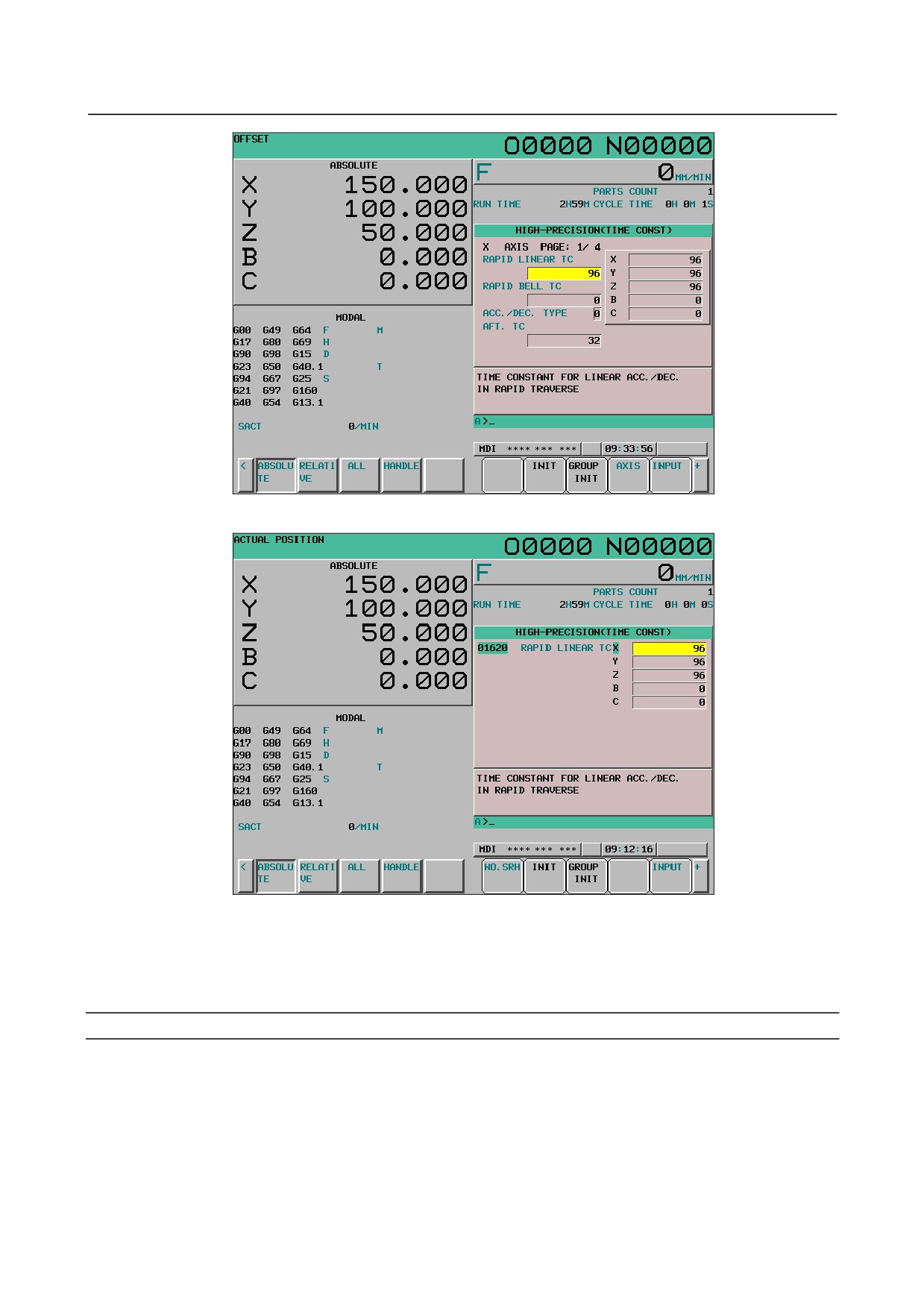
There are the following two display methods for high-precision setting.
1.
Display for each axis
The items to be set are displayed for each axis.
2.
Display for each item
Display is performed for each item to be set.
(Data of all axes is displayed for each item.)
- 642 -
B-64304EN/02
OPERATION 12.SETTING AND DISPLAYING DATA
Fig. 12.4.10.8 (a) High-precision setting screen (display for each axis) (10.4-inch)
Fig. 12.4.10.8 (b) High-precision setting screen (display for each item) (10.4-inch)
Screen display is switched between display for each axis and display for each item each time soft key
[CHANGE] is pressed.
(For the switching method, see "Parameter setting support screen
(servo
parameter)" earlier.)
Setting the high-precision setting screen
For the setting procedure, see "Parameter setting support screen (servo parameter)" earlier.
- 643 -
12.SETTING AND DISPLAYING DATA OPERATION
B-64304EN/02
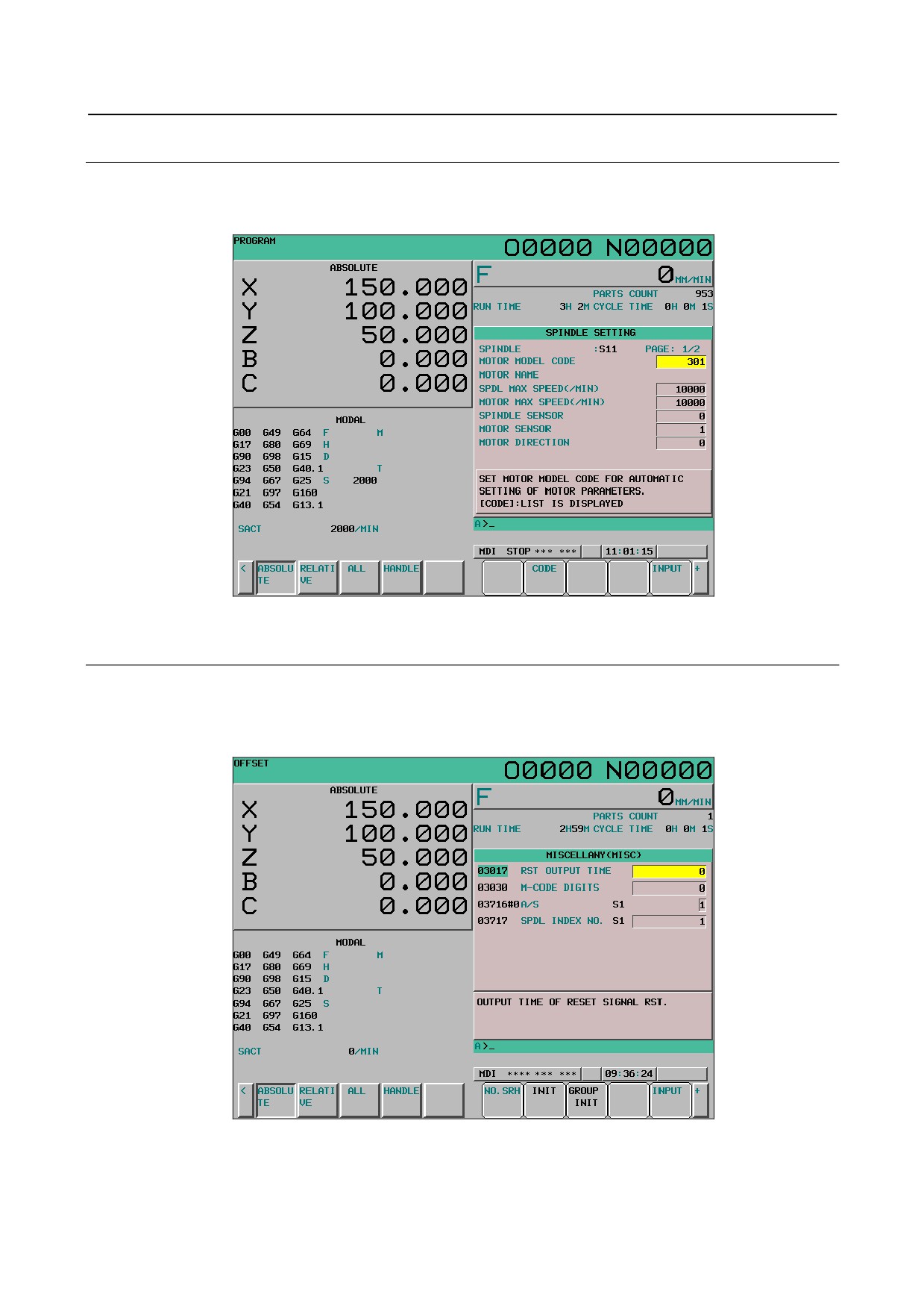
12.4.10.9 Displaying and setting the spindle setting screen
The parameters related to spindles can be displayed or changed.
For the display and setting methods, see "Parameter setting support screen (axis setting)" earlier.
Fig. 12.4.10.9 (a) Parameter setting support screen (spindle setting) (10.4-inch)
12.4.10.10 Displaying and setting the miscellaneous setting screen
Allocation of axis paths and setting of DI/DO and serial spindles can be performed. It is also possible to
initialize parameters to the default settings (FANUC recommended values).
For the display and setting procedures, see "Parameter setting support screen (axis setting)" earlier.
Fig. 12.4.10.10 (a) Parameter setting support screen (miscellaneous) (10.4-inch)
- 644 -
B-64304EN/02
OPERATION 12.SETTING AND DISPLAYING DATA
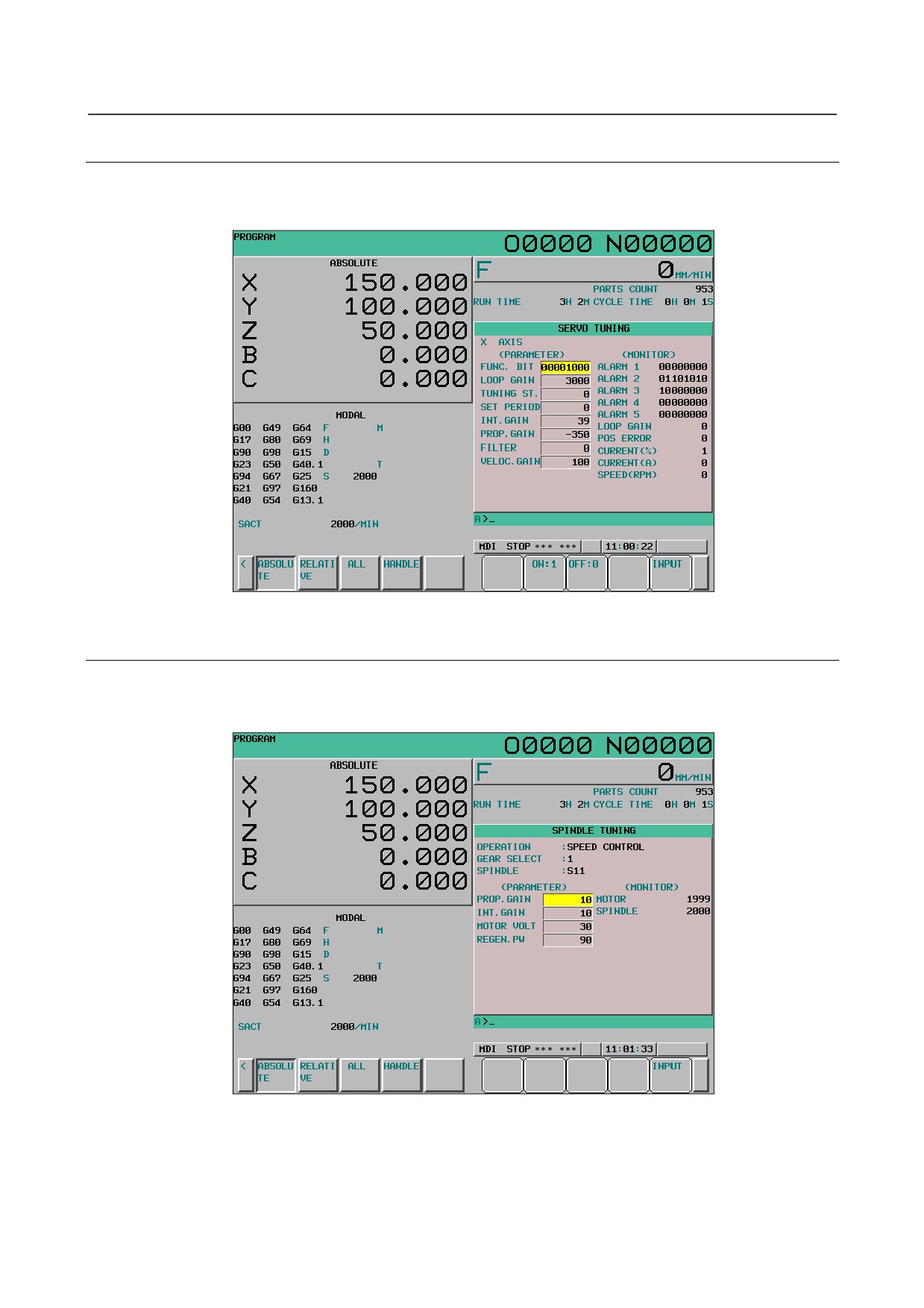
12.4.10.11 Displaying and setting the servo tuning screen
From the parameter setting support screen, the servo tuning screen can be displayed. For details of the
servo tuning screen, see the description of the servo tuning screen in Subsection III-12.4.4.
Fig. 12.4.10.11 (a) Servo tuning screen (10.4-inch)
12.4.10.12 Displaying and setting the spindle tuning screen
From the parameter setting support screen, the spindle tuning screen can be displayed. For details of the
spindle tuning screen, see the description of the spindle tuning screen in Subsection III-12.4.6.
Fig. 12.4.10.12 (a) Spindle tuning screen (10.4-inch)
- 645 -
12.SETTING AND DISPLAYING DATA OPERATION
B-64304EN/02
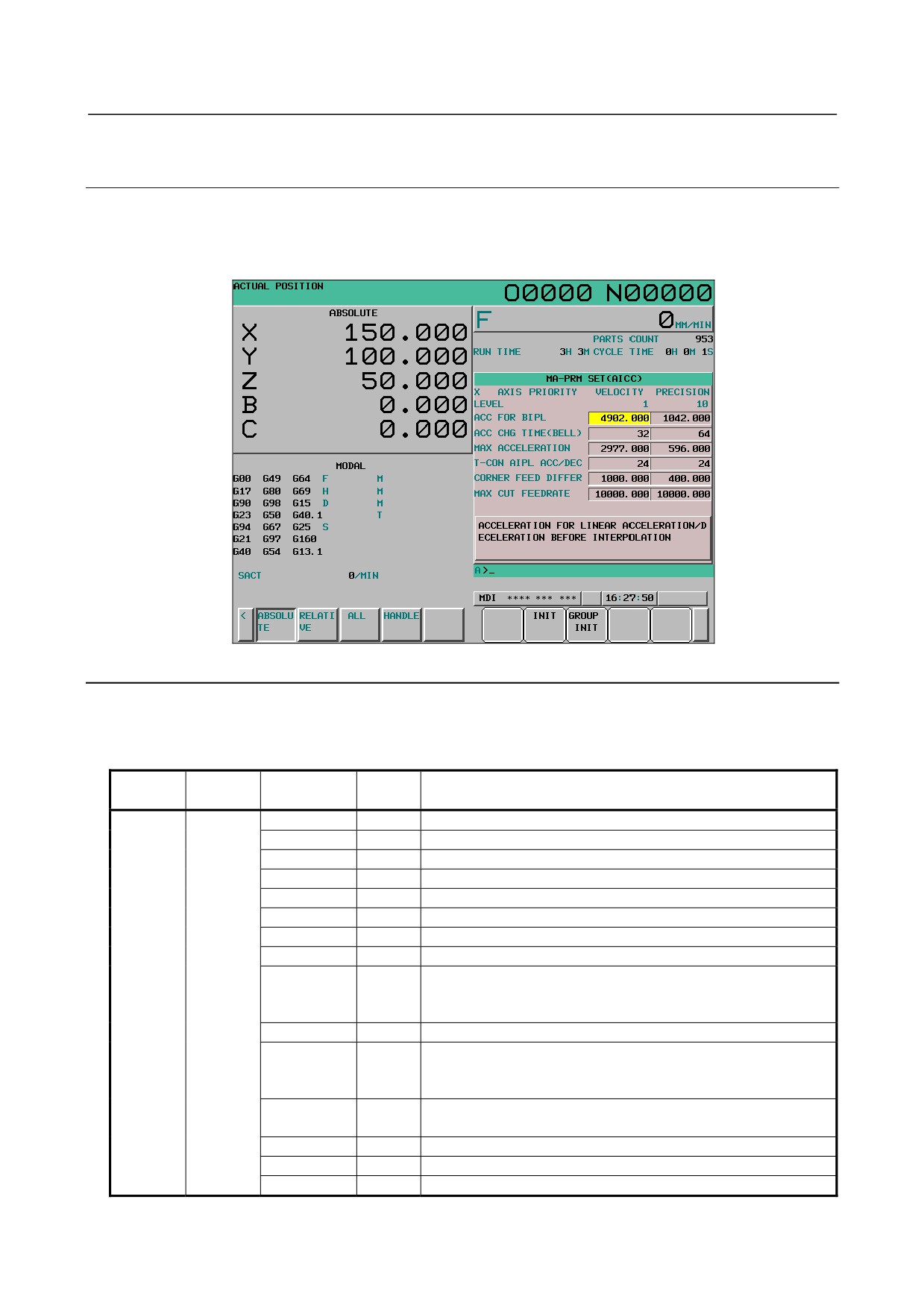
12.4.10.13 Displaying and setting the machining parameter tuning
screen
From the parameter setting support screen, the machining parameter tuning screen can be displayed. For
details of the machining parameter tuning screen, see the description of the machining parameter tuning
screen in Subsection III-12.4.9.
Fig. 12.4.10.13 (a) Machining parameter tuning screen (10.4-inch)
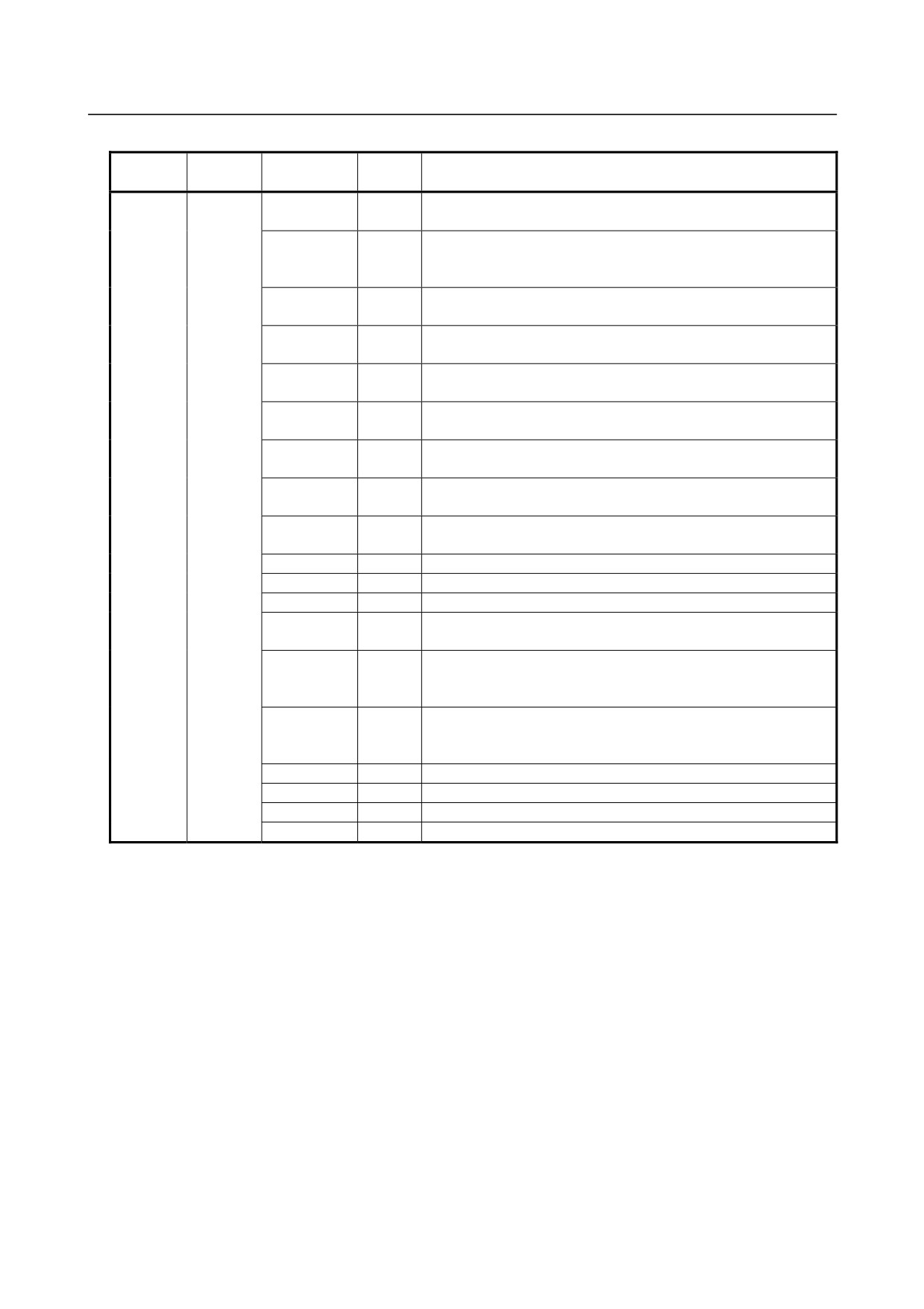
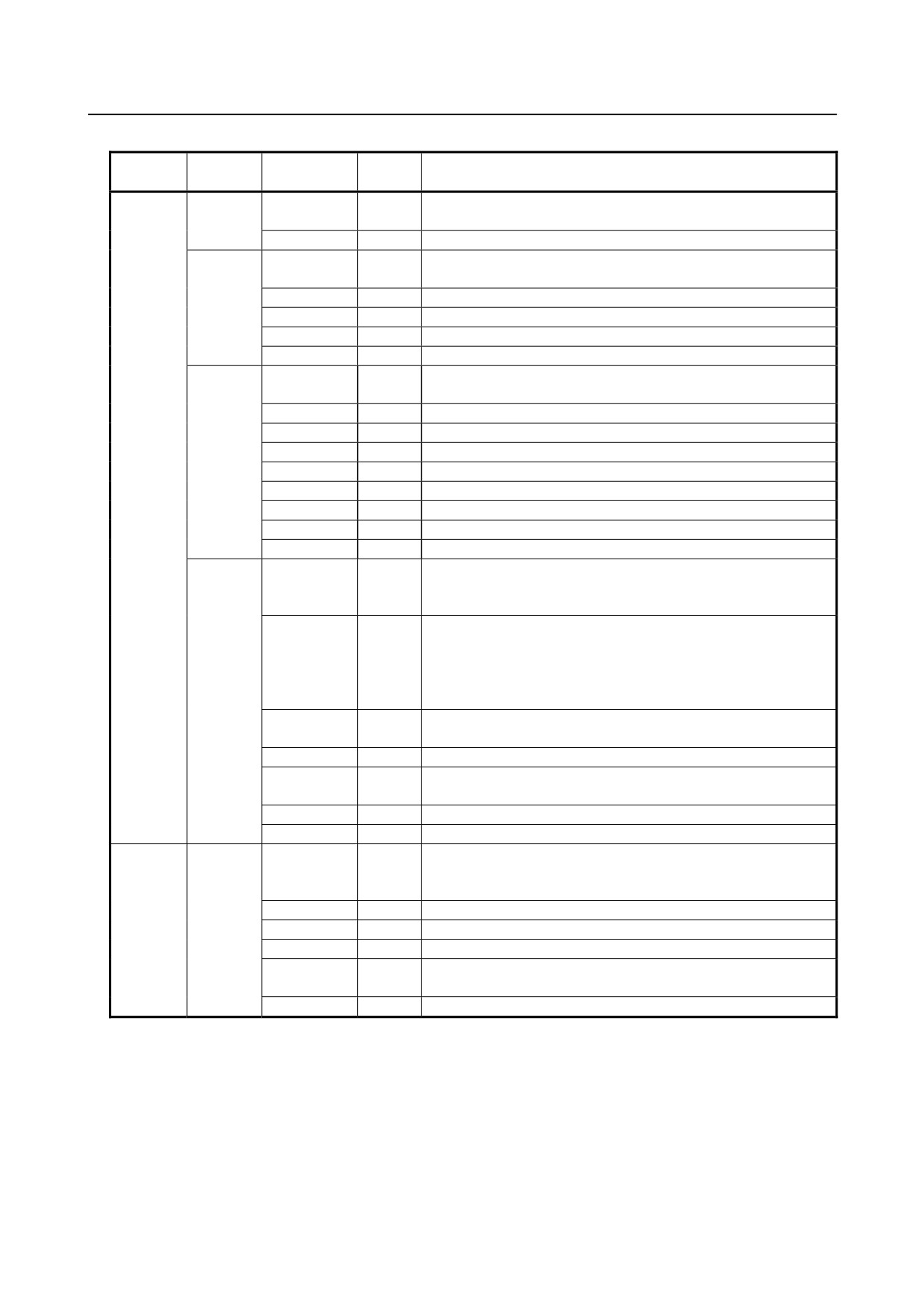
Explanation
-
Parameters displayed for parameter setting support
Table 12.4.10.13 (a) Parameters displayed for parameter setting support (1)
Parameter
Menu
Group
Name
Brief description
No.
SPINDLE
SPINDLE
3741
Maximum spindle speed
SETTING
SETTING
4000#0
Motor rotation direction
4001#4
Position coder rotation direction
4002#3,2,1,0
Spindle sensor switch
4004#3,2
Proximity switch
4005#0
Speed feedback method
4006#1
Gear ratio resolution
4010#2,1,0
Motor sensor type
4019#7
The parameters of the serial spindle are:
0: Set automatically.
1: Not set automatically.
(Not necessary for the analog spindle.)
4020
Maximum motor rotation speed (rpm)
4056
Motor rotation count per one revolution of spindle
Maximum motor speed/maximum spindle speed100 (rounding
off)
4133
Motor model code of the serial spindle
(Not necessary for the analog spindle.)
4171
Number of gears on the spindle side
4172
Number of gears on the motor side
4334
Speed detector arbitrary pulse count
- 646 -
B-64304EN/02
OPERATION 12.SETTING AND DISPLAYING DATA
Table 12.4.10.13 (b) Parameters displayed for parameter setting support (2)
Parameter
Menu
Group
Name
Brief description
No.
AXIS
BASIC
1001#0
INM
Least command increment on linear axes:
SETTING
0:Metric (millimeter machine)
1:Inch (inch machine)
1005#0
ZRNx
When an automatic operation (other than G28) is executed before
reference position return:
0:Alarm is issued (PS0224)
1:No alarm is issued.
1005#1
DLZx
Reference position return without dogs:
0:Disabled
1:Enabled
1006#0
ROTx
Setting of linear axes or rotary axis:
0:Linear axis
1:Rotation axis
1006#3
DIAx
Setting of the amount of travel:
0:Radius specification
1: Diameter specification
1006#5
ZMIx
Reference position return direction:
0:Plus direction
1:Minus direction
1008#0
ROAx
Rotation axis roll-over function:
0:Disabled
1:Enabled
1008#2
RRLx
With the amount of travel per revolution, relative coordinates are:
0:Not rounded
1:Rounded
1013#1
ISCx
Sets the least input increment and least command increment:
0:IS-B
1:IS-C
1020
Program name
1022
Sets each axis in the basic coordinate system.
1023
Servo axis number
1815#1
OPTx
A separate pulse coder is:
0:Not used
1:Used
1815#4
APZx
The correspondence between machine positions and
absolute-position detector positions is:
0:Not established
1:Established
1815#5
APCx
The position detector used is:
0:Other than an absolute-position detector
1:Absolute-position
detector
1825
Servo loop gain
1826
In-position width
1828
Positional deviation limit during travel
1829
Positional deviation limit during stop
- 647 -
12.SETTING AND DISPLAYING DATA OPERATION
B-64304EN/02
Table 12.4.10.13 (c) Parameters displayed for parameter setting support (3)
Parameter
Menu
Group
Name
Brief description
No.
AXIS
SPINDLE
3716#0
A/S
Sets the type of spindle motor:
SETTING
0:Analaog / 1:Serial.
3717
Spindle amplifier number
COORDI-
1240
Machine coordinate of the first reference position
NATE
1241
Machine coordinate of the second reference position
1260
Amount of travel per revolution of a rotary axis
1320
Positive direction border coordinates of stored stroke check 1
1321
Negative direction border coordinates of stored stroke check 1
FEED
1401#6
RDR
For a rapid traverse command, dry run is:
RATE
0:Disabled
1:Enabled
1410
Dry run feedrate
1420
Rapid traverse rate
1421
Rapid traverse override F0 rate
1423
Jog feedrate
1424
Manual rapid traverse rate
1425
FL feedrate for reference position return
1428
Reference position return feedrate
1430
Maximum cutting feedrate
ACC./DEC
1610#0
CTL
Acceleration/deceleration for cutting feed is:
0:Exponential acceleration/deceleration
1:Linear acceleration/deceleration after interpolation
1610#4
JGL
Acceleration/deceleration for jog feed is:
0:Exponential acceleration/deceleration
1:Same as acceleration/deceleration for cutting feed (The settings
of bit 1 (CTBx) and bit 0 (CTLx) of parameter No. 1610 are
followed.)
1620
Time constant for linear acceleration/deceleration for rapid
traverse
1622
Time constant for acceleration/deceleration for cutting feed
1623
FL feedrate for acceleration/deceleration after interpolation for
cutting feed
1624
Time constant for acceleration/deceleration for jog feed
1625
FL feedrate for exponential acceleration/deceleration for jog feed
MISCELLA
MISC
981
Sets the path of each axis.
-
NY
982
Sets the path of each spindle.
3017
Output time of reset signal
3030
Allowable number of digits of an M code
3716#0
A/Ss
Sets the type of spindle motor:
0:Analaog / 1:Serial.
3717
Spindle amplifier number
- 648 -

B-64304EN/02
OPERATION 12.SETTING AND DISPLAYING DATA
12.4.11 Periodic Maintenance Screen
Periodic maintenance screens are used for managing consumables (such as the backlight of a LCD unit
and backup batteries). By setting the name of a consumable, its life time, and the method for counting
down the life time, the life of the consumable can be counted down in the appropriate method set for the
consumable, and the remaining life time can be displayed.
With these screens, the user can easily manage consumables that require periodic replacement.
Explanation
There are four periodic maintenance screens: the status screen, the setting screen, the machine menu
screen, and the NC menu screen.
• Status screen:
Item names, remaining times, and count statuses are displayed, and item names are set.
• Setting screen:
Life times, remaining times, and count types (count-down method) are set.
• Machine menu screen:
The names of consumables in the machine can be registered.
• NC menu screen:
The names of consumables in the NC are already registered.
Using periodic maintenance screens
<1> Referencing a periodic maintenance screen
Display the status screen. For the meanings of items on the status screen, see Status screen.
<2> Adding the name of a new consumable item to a periodic maintenance screen or editing an existing
consumable item on the screen
The name of a consumable item can be added or edited on the machine menu screen. For details, see
Machine menu screen.
<3> Adding or editing a life time, remaining time, and a method of counting down the remaining time for
a consumable on a periodic maintenance screen
A life time and remaining time can be added or edited on the setting screen. For details, see Setting
screen.
<4> Newly displaying the item name and remaining time of a consumable on a periodic maintenance
screen.
1
Setting an item name
Select the item name of a consumable to be displayed from the machine menu screen or NC
menu screen, or enter the name using the MDI keys. For the procedure, see Item name in
Status screen.
2
Setting a life time, remaining time, and count type
Select the life time, remaining time, and count type of a consumable to be displayed from the
setting screen. For the procedure, see Remaining time in Status screen.
Procedure for displaying a periodic maintenance screen
1
Press function key
2
Press the continuous menu key
several times to display [PERIOD MAINTE] ([MAINTE] for
the 8.4-inch display unit).
3
Press soft key [PERIOD MAINTE] to display the periodic maintenance screen.
- 649 -
12.SETTING AND DISPLAYING DATA OPERATION
B-64304EN/02
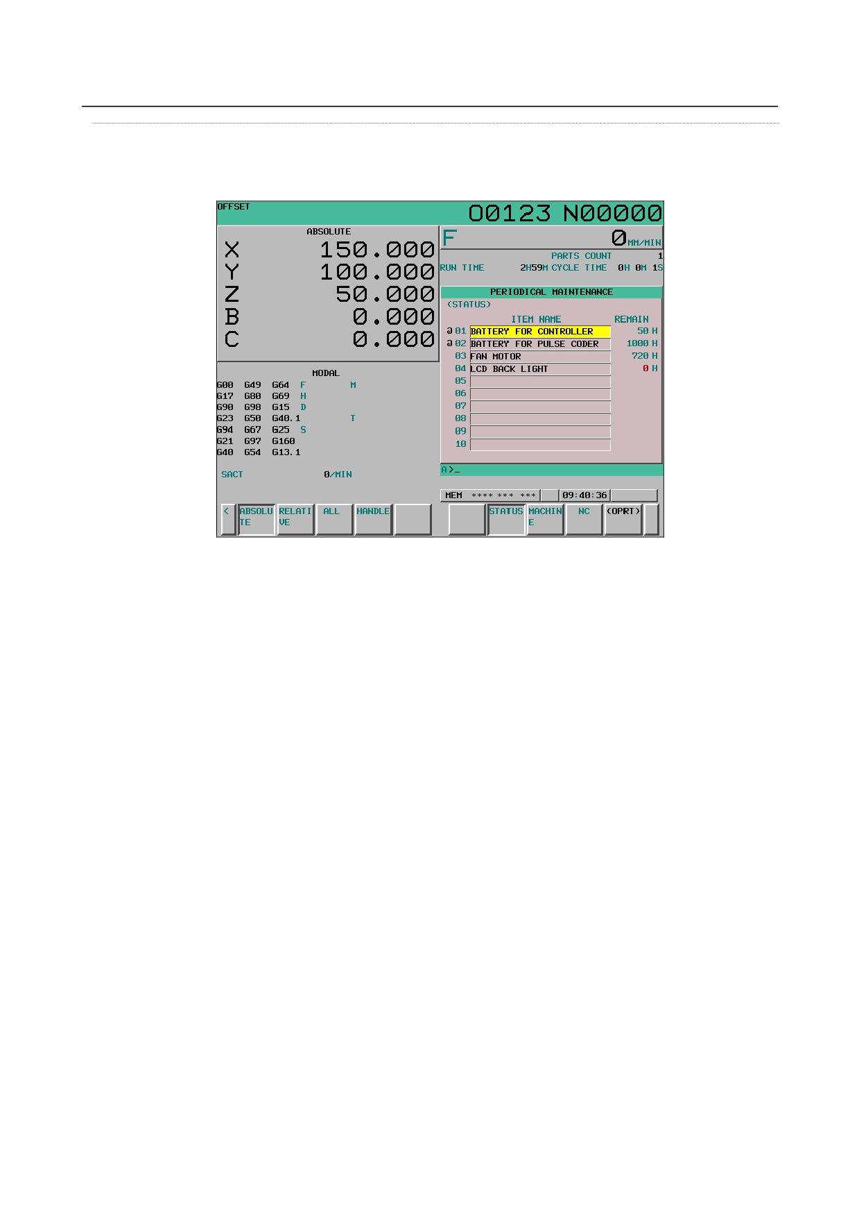
Status screen
When soft key [STATUS] is pressed, the status screen is displayed. The status screen shows the item
names, count statuses, and remaining times of managed consumables.
Fig. 12.4.11 (a) Status screen (10.4-inch)
-
Item name
As the item name, set the name of a consumable to be managed by periodic maintenance. To set an item
name, select a name from the machine menu screen or NC menu screen, or directly enter the name using
the MDI keys.
Setting an item name from a menu screen
1
On the status screen, move the cursor to a target item name, press soft key [(OPRT)], then press soft
key [ENTRY].
2
Press soft key [MACHINE] or [NC] to display the machine menu screen or NC menu screen.
3
Move the cursor to an existing item name on the menu screen, press soft key [(OPRT)], and press
soft key [SELECT] then [EXEC] successively.
4
The screen display returns to the status screen, and the item name selected on the menu screen is
added to the status screen.
Initially, there is no item name set on the machine menu screen, so item names must be registered in
advance. For the registration method, see the description of the procedure for registering item names on
the machine menu screen.
Setting an item name using the MDI keys
1
Press soft key [(OPRT)].
2
Type the alphanumeric characters to be input, then press soft key [INPUT].
3
The entered item name is registered on the status screen.
When soft key [+INPUT] is pressed instead of soft key [INPUT], the entered characters can be added to
an existing item name.
When typing 2-byte characters, type "*" before and after the character codes. The character codes must
conform to FANUC codes. (See Appendix G, "FANUC 2-BYTE CHARACTER CODE TABLE".)
An item name to be registered must be up to 24 characters long if it consists of alphanumeric characters
only; or it must be up to 12 characters long if it consists of 2-byte characters only.
Example: To register "LCD バックライト", enter the following:
>LCD*110E10F410CC114010B610FE*_
- 650 -
B-64304EN/02
OPERATION 12.SETTING AND DISPLAYING DATA
NOTE
1 An asterisk "*" is used as a control code, so it cannot be used in item names. In
addition, characters "[", "]", "(", and ")" cannot be used in item names.
2 When an item name consisting of both alphanumeric characters and 2-byte
characters is registered, the warning "DATA OUT OF RANGE" may be output.
Deleting an item name
To delete a registered item name, move the cursor to the item name, press soft key [ERASE], then press
soft key [EXEC].
When an item name is deleted, its life time, remaining time, and count type are deleted at the same time.
-
Remaining time
As the remaining time, the period of time left until the time for replacement is reached by count down
operation is displayed.
If the percentage of the remaining time to the life time has reached to the value (%) specified by
parameter No. 8911, or smaller, the remaining time is displayed in red.
Even after the life time has expired, count down operation continues.
Setting the remaining time
1
On the status screen, place the cursor on an item for which the remaining time is to be set (the item
name must have been set in advance).
2
Press soft key [(OPRT)], then press soft key [CHANGE].
3
The screen display changes to the setting screen.
4
Set the life time, remaining time, and count type. For the setting method and other information, see
Setting screen.
NOTE
On the status screen, the remaining time and life time cannot be set.
These items must be set on the setting screen.
-
Count status
The count status is indicated on the left side of the item number as follows:
Indication
Count status
Blank
Counting stopped
@
Counting in progress
㧖
Life expired
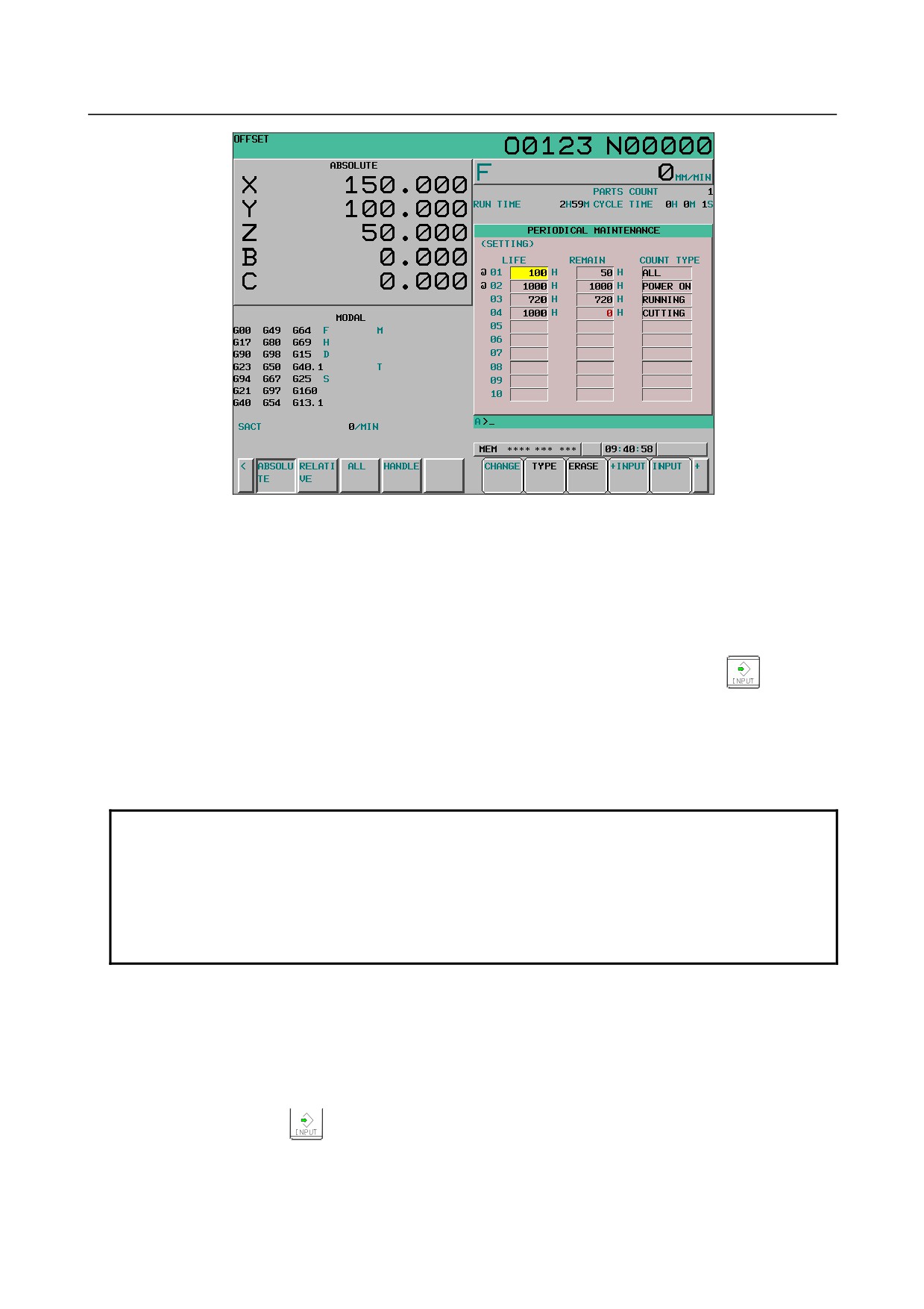
Setting screen
On the setting screen, the life time, remaining time, and count type of a managed consumable are set.
- 651 -
12.SETTING AND DISPLAYING DATA OPERATION
B-64304EN/02
Fig. 12.4.11 (b) Setting screen
Display procedure
1
When the status screen is displayed, press soft key [(OPRT)].
2
Press soft key [CHANGE].
-
Life time
Set the life time of a consumable.
Move the cursor to an existing item, type a life time, then press soft key [INPUT] (or the
key). The
life time is then set, and the same value is set also as the remaining time.
At this time, "------" is indicated in the count type field.
When soft key [+INPUT] is pressed, the entered value can be added to the life time already set. The same
value as the added value is added also to the remaining time.
A value ranging from 0 to 65535 (in hours) can be set.
NOTE
1 If a setting operation is attempted when the item name is not registered, the
warning "EDIT REJECTED" is issued.
2 If a value exceeding the valid range is entered, the warning "DATA IS OUT OF
RANGE" is issued.
3 If soft key [ERASE] or [TYPE] is pressed, the warning "EDIT REJECTED" is
issued.
-
Remaining time
The period of time left until the time for replacement is reached by count down operation is indicated.
If the percentage of the remaining time to the life time has reached the value (%) specified by parameter
No. 8911, or smaller, the remaining time is displayed in red.
Even after the life time has expired, count down operation continues.
Move the cursor to the remaining time of a target registered number, type a remaining time, then press
soft key [INPUT] (or the
key). The remaining time is then set.
When soft key [+INPUT] is pressed, the entered value can be added to the remaining time already set.
A value ranging from 0 to (life time) can be set.
When soft key [ERASE] then soft key [EXEC] are pressed, the same value as the life time is set.
- 652 -
B-64304EN/02
OPERATION 12.SETTING AND DISPLAYING DATA
NOTE
1 If a setting operation is attempted when the item name or life time is not
registered, the warning “EDIT REJECTED” is issued.
2 When a value exceeding the valid range is entered, the warning “DATA IS OUT
OF RANGE” is issued.
3 If soft key [TYPE] is pressed, the warning “EDIT REJECTED” is issued.
-
Count type
As the count type, select the way of counting.
Place the cursor on the count type of a target registration number, then press soft key [TYPE]. Count
types are displayed as soft keys as shown below. Select one of these soft keys, then press soft key
[EXEC].
Soft key
Meaning
Indication
[NO CNT]
Counting is not performed (stopped)
— — — — — —
[ALL]
Counting is performed at all times
All times
[POWER ON]
Counting is performed when power is on.
When power is on
[RUN]
Counting is performed when operation is in progress.
When operation is in progress
[CUT]
Counting is performed when cutting is being performed.
When cutting is being performed
NOTE
1 If a setting operation is attempted when the item name or life time is not
registered, the warning “EDIT REJECTED” is issued.
2 Soft keys [INPUT] and [+INPUT] have no effect.
3 When counting is performed at all times, a 24-hour error is generated in leap
year.
4 If soft key [ERASE] is pressed, the warning “EDIT REJECTED” is issued.
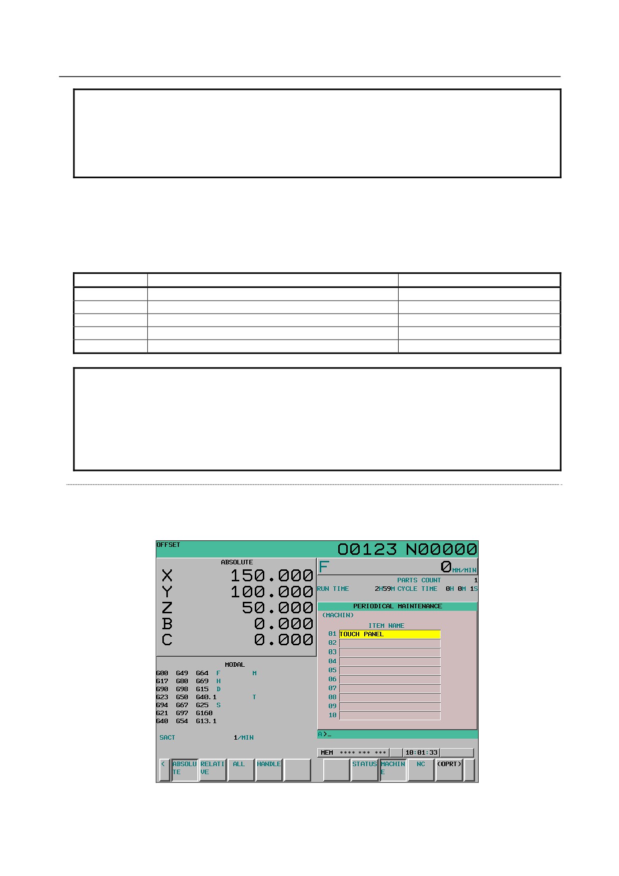
Machine menu screen
On the machine menu screen, the names of consumables of the machine are registered. From this screen,
item names can be added to the status screen. For the method of addition to the status screen, see the
description of the status screen.
Fig. 12.4.11 (c) Machine menu screen
- 653 -
12.SETTING AND DISPLAYING DATA OPERATION
B-64304EN/02
-
Displaying the screen
1
When the status screen is displayed, press soft key [MACHINE].
On the machine menu screen, item names can be registered using one of the following two methods:
• Registration from a program
• Registration using the MDI keys
-
Registration from a program
By executing a program having the following format, an item name can be registered in the menu of the
machine:
Format
G10 L61 Px [n]
X Registration number
n Item name, format: [alphanumeric-characters*2-byte-characters*alphanumeric-characters]
-
Registration using the MDI keys
When the cursor is moved on the machine menu screen, an item name is entered in the following format,
and soft key [INPUT] (or the
key) is pressed, then the item name can be registered on the machine
menu screen.
When soft key [+INPUT] is pressed, the typed characters can be added to an already registered item
name.
Format
Alphanumeric-characters*2-byte-characters*alphanumeric-characters
Description of the format
Alpha numeric characters must be entered directly.
Two-byte codes must conform to FANUC codes. (See Appendix G, "FANUC 2-BYTE CHARACTER
CODE TABLE".)
To register a two-byte character, enclose the two-byte code with asterisks (*). An item name to be
registered must be up to 24 characters long if it consists of alphanumeric characters only; or it must be up
to 12 characters long if it consists of 2-byte characters only.
Example) To register "LCD バックライト", enter the following:
Registration with a program
G10 L61 P1 [LCD*110E10F410CC114010B610FE*]
Registration with MDI keys
>LCD*110E10F410CC114010B610FE*_
NOTE
1 An asterisk "*" is used as a control code, so it cannot be used in item names. In
addition, characters "[", "]", "(", and ")" cannot be used in item names.
2 When an item name consisting of both alphanumeric characters and 2-byte
characters is registered, the warning “DATA IS OUT OF RANGE” may be output.
3 When a blank item name is selected on the machine screen, the warning “EDIT
REJECTED” is issued.
- 654 -
B-64304EN/02
OPERATION 12.SETTING AND DISPLAYING DATA
To delete a registered item name, move the cursor to the item name, press soft key [ERASE], then press
soft key [EXEC].
NC menu screen
On the NC menu screen, the names of NC consumables are registered. From this screen, an item name
can be registered on the status screen. For the method of registration to the status screen, see the
description of the status screen.
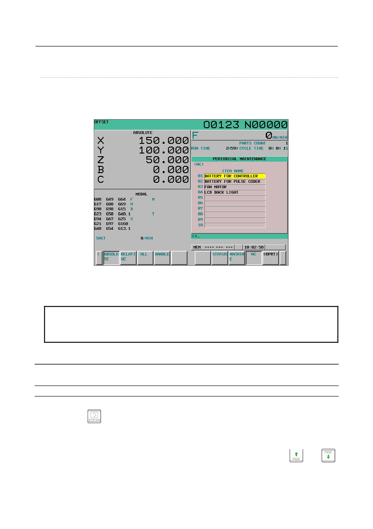
Fig. 12.4.11 (d) NC menu screen
-
Displaying the screen
1
When the status screen is displayed, press soft key [NC].
NOTE
On the NC menu screen, the registration, deletion, and I/O of item names cannot
be performed.
When a blank item name is selected, a blank is set.
12.4.12 System Configuration Screen
The system configuration screen provides information about the types of installed hardware and software.
Procedure for displaying the screen
Procedure
1
Press the
key to display a screen that shows parameters and other information.
2
Press soft key [SYSTEM]. The system configuration screen is displayed.
There are two types of system configuration screens: the hardware configuration screen and the software
configuration screen. The screen display can switch between these screens by using
and
When soft key [SERVO INFO] or [SPINDLE INFO] is pressed, information about the connected servo
system or spindles is displayed.
- 655 -
12.SETTING AND DISPLAYING DATA OPERATION
B-64304EN/02
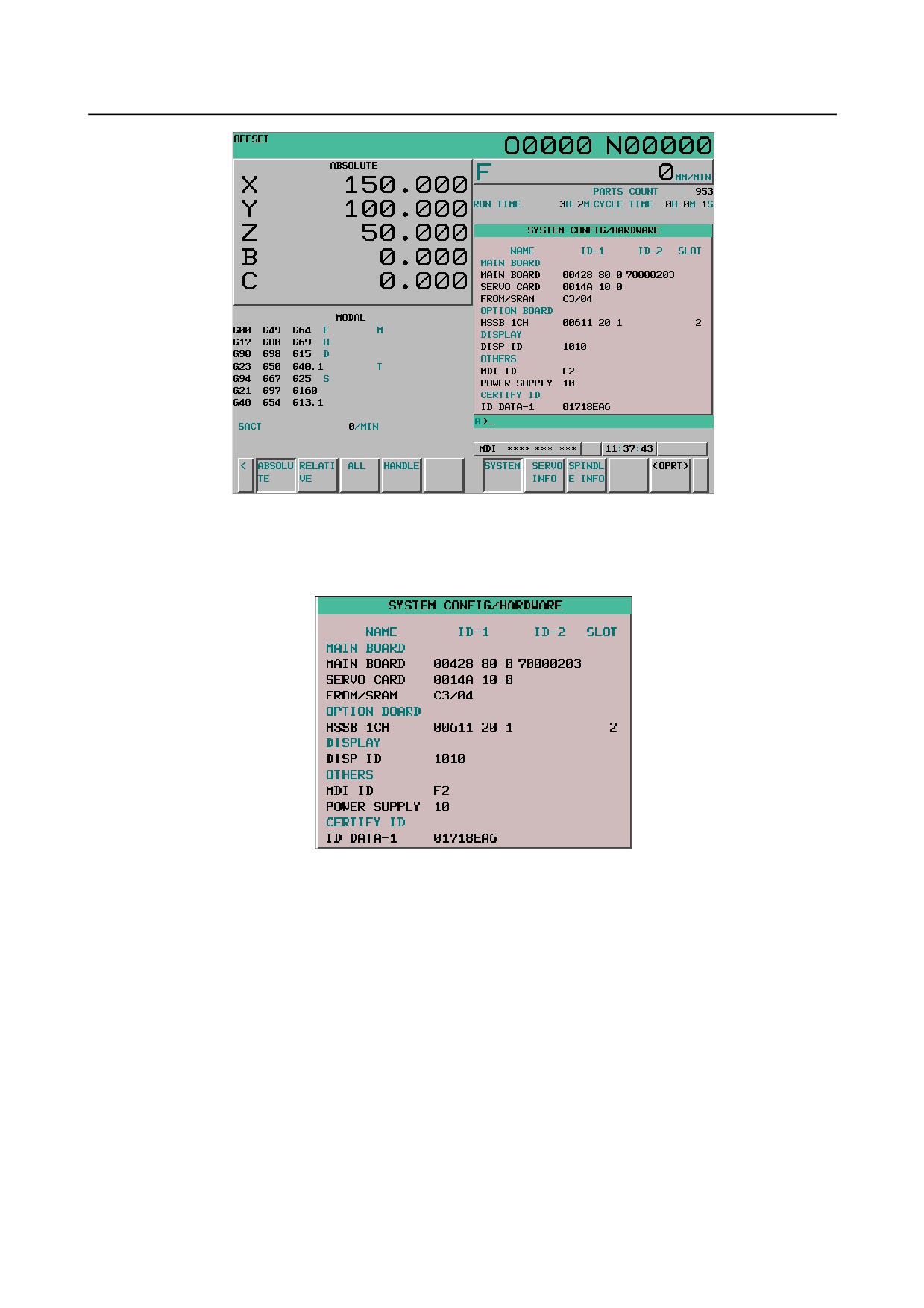
Fig. 12.4.12 (a) System configuration screen
Hardware configuration screen
This screen shows the names and IDs of the hardware used by the NC.
Fig. 12.4.12 (b) Hardware configuration screen
Software configuration screen
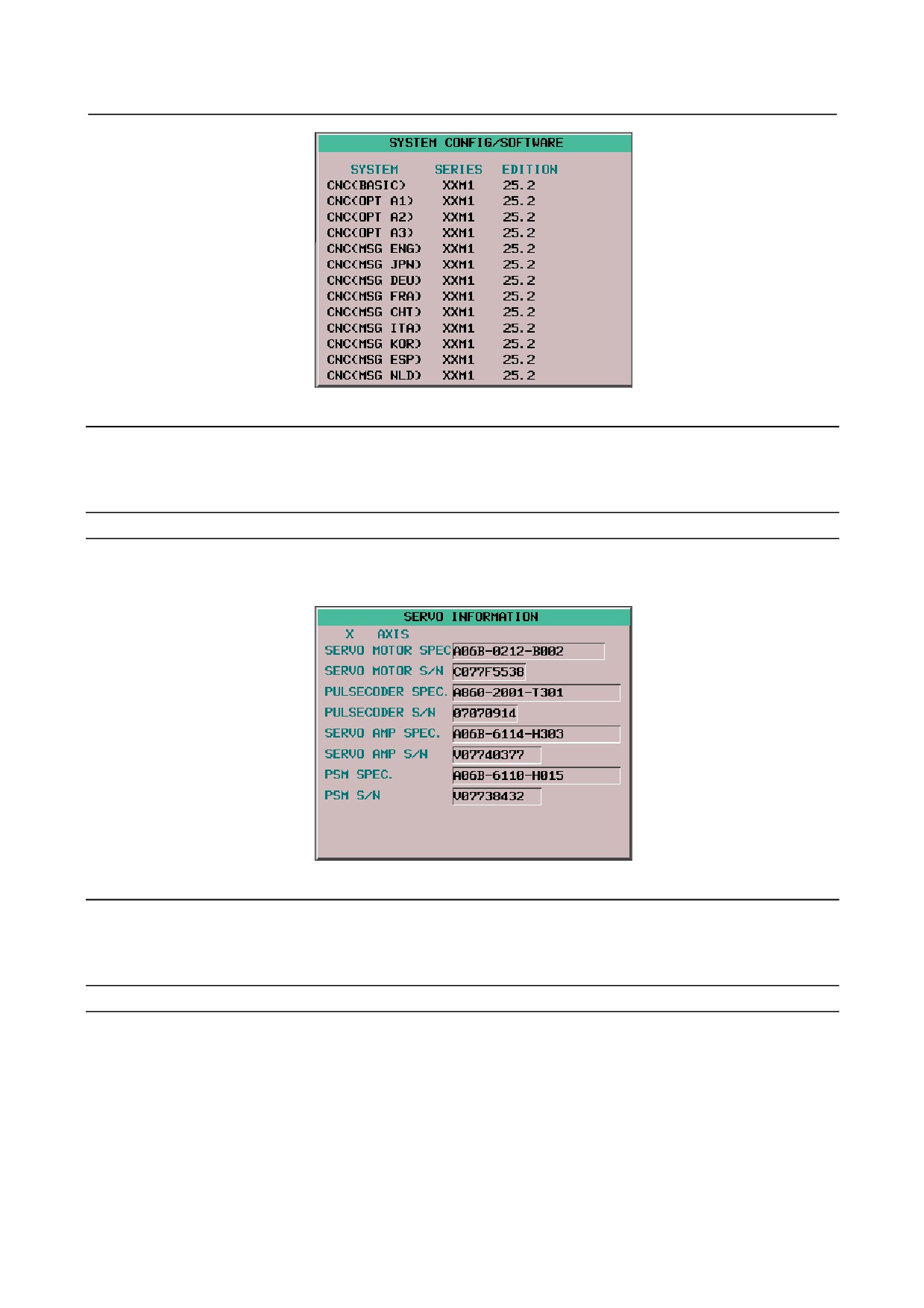
This screen shows the names and series/editions of the software used by the NC.
- 656 -
B-64304EN/02
OPERATION 12.SETTING AND DISPLAYING DATA
Fig. 12.4.12 (c) Software configuration screen
Servo information screen
When a servo system is connected to the NC, ID information of the connected servo devices (servo
motors and servo amplifier modules) can be displayed on the NC.
Displaying the screen
1
When the system configuration screen is displayed, press soft key [SERVO INFO].
2
The servo information screen is displayed.
Fig. 12.4.12 (d) Servo information screen
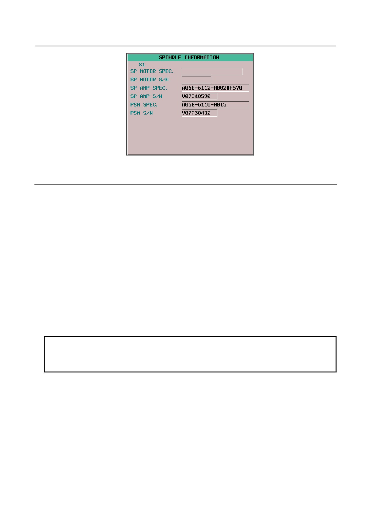
Spindle information screen
When a spindle system is connected to the NC, the ID information of the connected spindle devices
(spindle motors and spindle amplifier modules) can be displayed on the NC.
Displaying the screen
1
When the system configuration screen is displayed, press soft key [SPINDLE INFO] ([SPINDLE]
for the 8.4-inch display unit).
2
The spindle information screen is displayed.
- 657 -
12.SETTING AND DISPLAYING DATA OPERATION
B-64304EN/02
Fig. 12.4.12 (e) Spindle information screen
12.4.13 Overview of the History Function
The history function records the operations performed by the operator, alarms that occurred, and external
operator messages and checks their history or outputs them as history data.
Conditions for recording history
a
Display screen
A history of screens other than the operation history screen is recorded.
b Signal selection
Up to 60 I/O signals can be selected so that they can be recorded in history data.
c
Parameter setting
With parameters, it is possible to separately set whether to record an MDI key operation history
and an external operator message history, add external alarms and messages, and record data
modification histories such as operation histories of parameters, tool offsets, workpiece offsets
(workpiece shift amounts), custom macro common variables, and I/O signals.
Data output
All history data stored can be output to external input/output devices. (See Subsection 12.4.15.5,
"Outputting all history data".)
NOTE
1 All history data remains even after the power is turned off.
Clearing memory also deletes these history data items.
2 Set the time and date correctly on the setting screen.
- 658 -
B-64304EN/02
OPERATION 12.SETTING AND DISPLAYING DATA
12.4.13.1 Alarm history
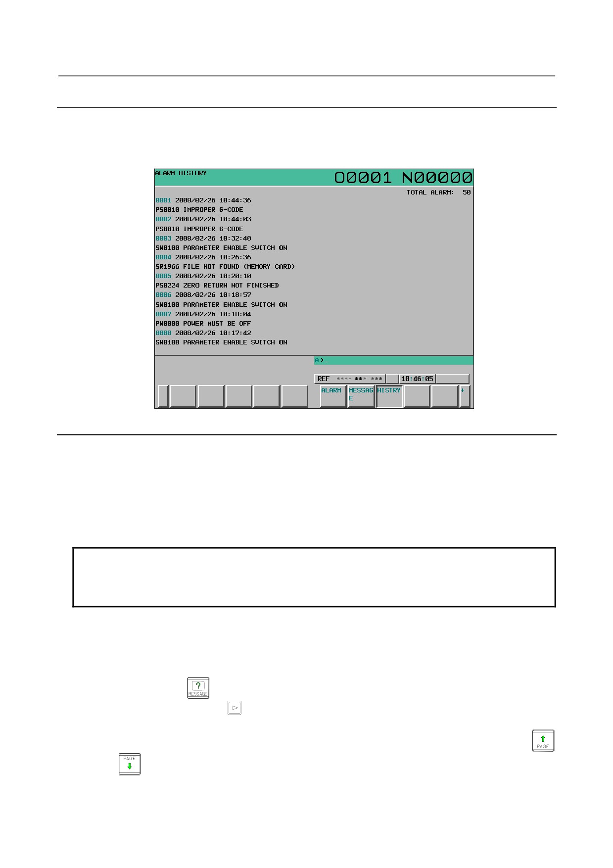
The alarm generated in CNC is recorded. The alarm of 50 times is recorded, and it is displayed from the
new one sequentially. If the amount of alarm history data exceeds 50 items, alarm history data is
automatically deleted in sequence from the oldest one.
Fig. 12.4.13.1 (a) Alarm history screen
Screen display
Issued alarms are displayed sequentially from the latest alarm.
The following information is displayed for each alarm:
• Path name (only when 2-path control is performed)
• Time and date of alarm occurrence
• Type and number of the alarm
• Alarm message
NOTE
To record also external alarm and macro alarm messages as history data, set bit
3 (EAH) of parameter No. 3112 to 1, and at the same time set bit 7 (HAL) of
parameter No. 3196 to 0.
When a name such as a path name, axis name, or spindle name has been changed after the issuance of an
alarm, a newly assigned name is displayed on the alarm history screen.
Procedure
1
Press function key
2
Press continuous menu key
several times until soft key [HISTRY] is displayed.
3
Press soft key [HISTRY]. The alarm history screen is then displayed.
4
The screen display can be changed to the previous page and the next page by using page keys
and
- 659 -
12.SETTING AND DISPLAYING DATA OPERATION
B-64304EN/02
Erasing alarm history data from the alarm history screen
Procedure
1
Display the alarm history screen.
2
Press soft key [(OPRT)].
3
Press soft key [CLEAR]. Alarm history data is then erased.
Display of external alarms and macro alarms
The following parameter can be used to record a message as well as the corresponding alarm number in
alarm history when an external alarm or macro alarm occurs.
#7
#6
#5
#4
#3
#2
#1
#0
3112
EAH
[Data type] Bit
#3 EAH Messages of the external alarm/macro alarm in alarm or operation history:
0: Not recorded
1: Recorded
NOTE
This parameter is valid when bit 7 (HAL) of parameter No. 3196 is
set to 0.
#7
#6
#5
#4
#3
#2
#1
#0
3195
EKE
[Data type] Bit
#7 EKE The contents of operation history and alarm history
0: cannot be deleted.
1: can be deleted.
#7
#6
#5
#4
#3
#2
#1
#0
3196
HAL
[Data type] Bit
#7 HAL When an alarm is issued, additional information (modal data, absolute coordinates, and
machine coordinates present at the issuance of the alarm) is:
0: Recorded in the operation history.
1: Not recorded in the operation history.
- 660 -
B-64304EN/02
OPERATION 12.SETTING AND DISPLAYING DATA
12.4.13.2 External operator message history
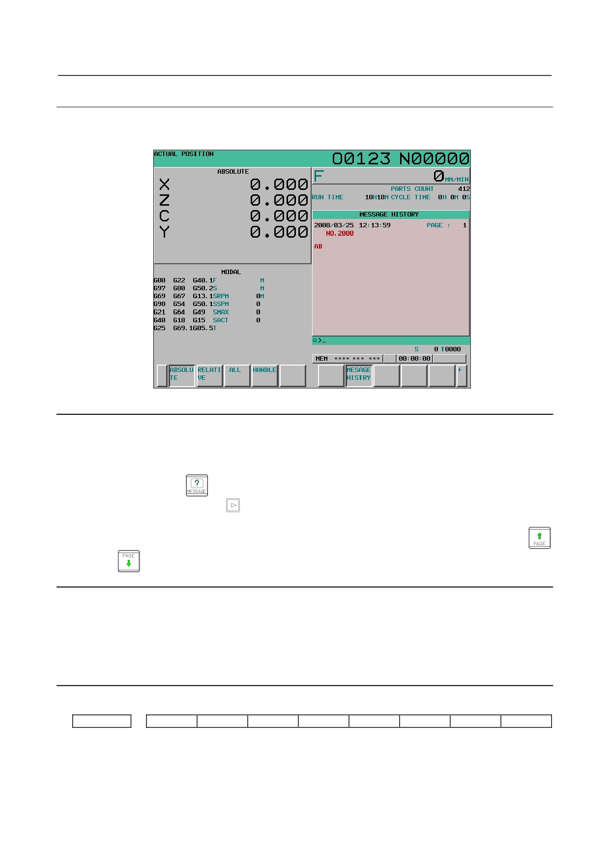
External operator message can be stored as history. And, stored history can be seen on the external
operator message history screen.
Fig. 12.4.13.2 (a) External operator message history screen
Screen display
To display the external operator message history screen, set bit 2 (OMH) of parameter No. 3112 to 1.
Procedure
1
Press function key
2
Press continuous menu key
several times until soft key [MESSAGE HISTRY] is displayed.
3
Press soft key [MESSAGE HISTRY]. The external operator message history screen is displayed.
4
The screen display can be changed to the previous page and the next page by using page keys
and
Erasing history data from the external operator message history screen
Procedure
1
Display the external operator message history screen.
2
Press soft key [(OPRT)].
3
Press soft key [CLEAR]. The external operator message history data is then erased.
Parameter setting
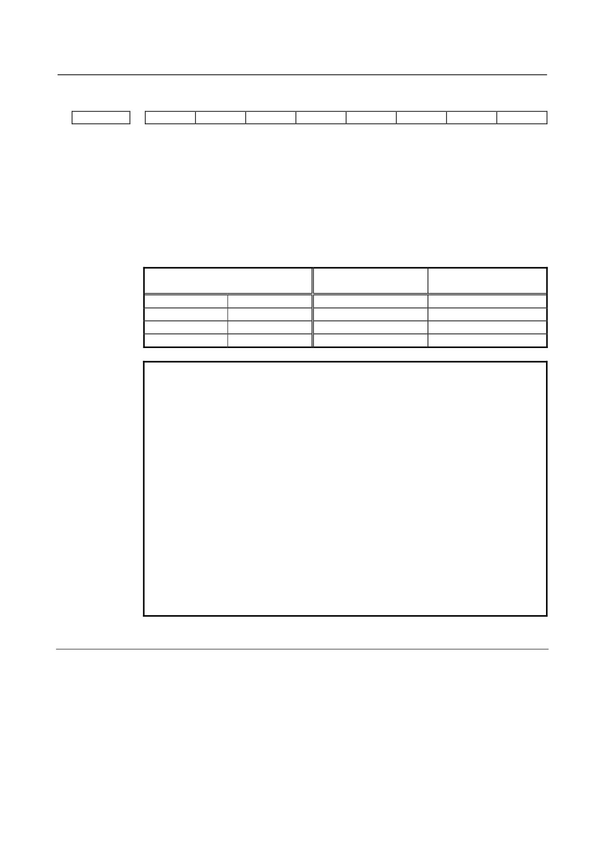
#7
#6
#5
#4
#3
#2
#1
#0
3112
OMH
[Data type] Bit
#2 OMH The external operator message history screen is:
0: Not displayed.
1: Displayed.
- 661 -
12.SETTING AND DISPLAYING DATA OPERATION
B-64304EN/02
#7
#6
#5
#4
#3
#2
#1
#0
3113
MS1
MS0
HMC
[Data type] Bit
#0 HMC The contents of the external operator message history:
0: Cannot be erased.
1: Can be erased.
#6
MS0
#7
MS1 Set the combination of the number of characters and the number of messages to be
preserved in the external operator message history.
Maximum number of
Parameter
Number of messages
characters
MS1=0
MS0=0
255
8
MS1=0
MS0=1
200
10
MS1=1
MS0=0
100
18
MS1=1
MS0=1
50
32
NOTE
1 Although up to 255 characters can be specified for each external
operator message, you can use the combination of bits 6 (MS0)
and 7 (MS1) of parameter No. 3113 to limit the number of
characters and select the number of messages to be preserved in
the external operator message history.
2 The settings of bits 6 (MS0) and 7 (MS1) of parameter No. 3113
take effect the next time the power is turned on. The external
operator message history is erased at that time.
3 Even though you change the settings of bits 6 (MS0) and 7 (MS1)
of parameter No. 3113, the alarm PW0000, "POWER MUST BE
OFF" is not issued. You must however turn on the power again
before the new settings can take effect.
4 If text (such as single-byte katakana or kanji characters) is entered
in character code, the number of characters recorded in the
external operator message history may be smaller than the
maximum number of characters set by bits 6 (MS0) and 7 (MS1) of
parameter No. 3113.
12.4.13.3 Operation history
This function displays a history of the operator's key operations and signal operations made when a
failure occurred or an alarm was issued, and also information about alarms.
The following data is recorded:
a
Operation history
i
MDI key operations made by the operator
ii
I/O signal (X,Y,G,F) on/off switching
b Alarm history
i
Alarms issued
ii
Modal information in a block executed and coordinates observed when an alarm was issued
(Not displayed on the screen)
- 662 -
B-64304EN/02
OPERATION 12.SETTING AND DISPLAYING DATA
c
Data modification history
i
Modification of tool offset data
(When bit 0 (HTO) of parameter No. 3196 is set to 1)
ii
Modification of workpiece offset data/extended workpiece offset data/workpiece shift
(T
series)
(When bit 1 (HWO) of parameter No. 3196 is set to 1)
iii
Modification of parameters
(When bit 2 (HPM) of parameter No. 3196 is set to 1)
iv Modification of custom macro common variable data
(When bit 3 (HMV) of parameter No. 3196 is set to 1)
d External operator message history and macro message history
(When bit 6 (HOM) of parameter No. 3196 is set to 0)
e
Time stamp (time and date)
With some exceptions, history data of the operation history and alarm history can be viewed on the
operation history screen. (The data modification history, external operator message history, and alarm
messages are not displayed.)
All recorded history data can be output to external input/output devices.
NOTE
Up to about 8000 items of history data can be recorded if the data includes
history data of MDI key operations only. However, because history data varies in
size, the maximum number of history data items that can be recorded is not
fixed.
Parameter setting
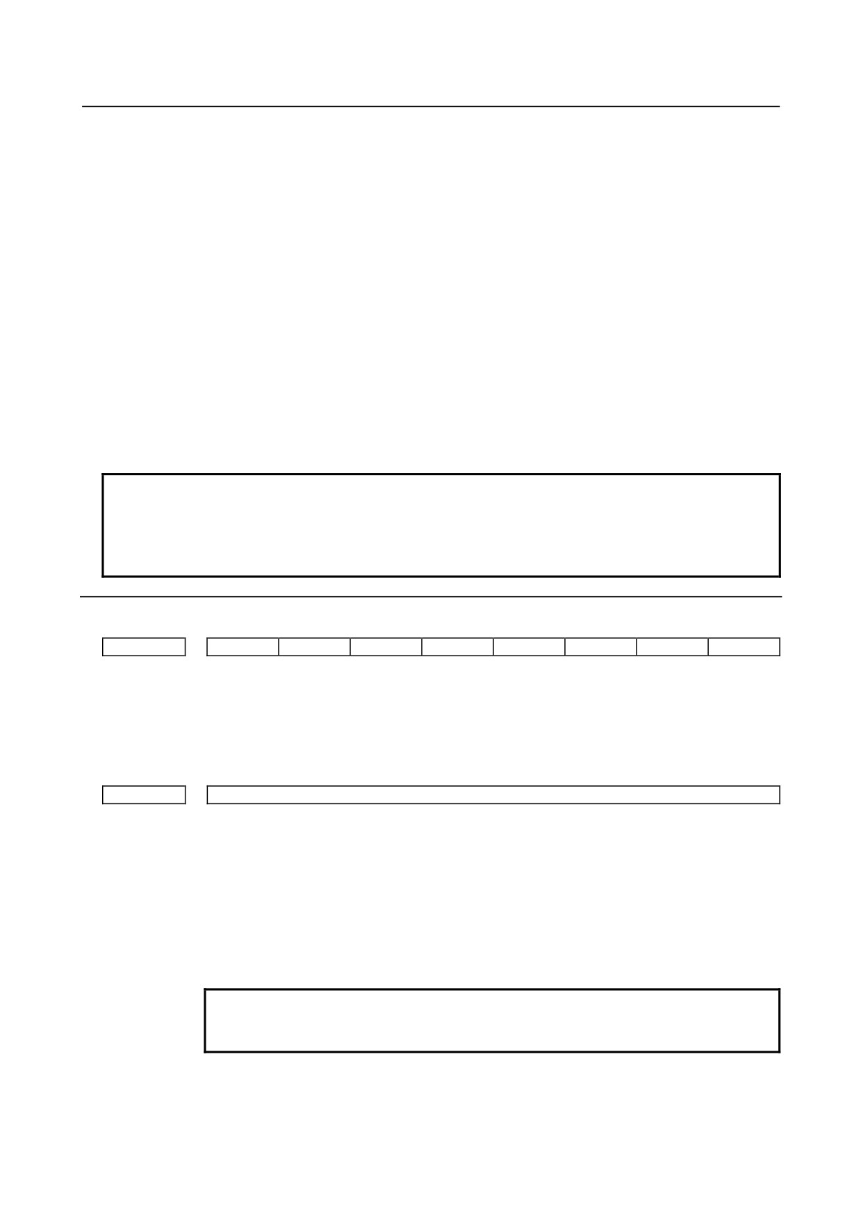
#7
#6
#5
#4
#3
#2
#1
#0
3106
OPH
[Data type] Bit
# 4
OPH The operation history screen is:
0: Not displayed.
1: Displayed.
3122
Time interval used to record time data in operation history
[Input type] Parameter input
[Data type] Word path
[Unit of data] min
[Valid data range] 0 to 1440
When history data is recorded within a set time period, the time for each set time period is
recorded in the history data.
When 0 is set, the specification of a time period of 10 minutes is assumed.
If no data is recorded within a set time period, the time for that period is not recorded.
NOTE
When two paths are present, set this parameter to the same value
for both path.
- 663 -
12.SETTING AND DISPLAYING DATA OPERATION
B-64304EN/02
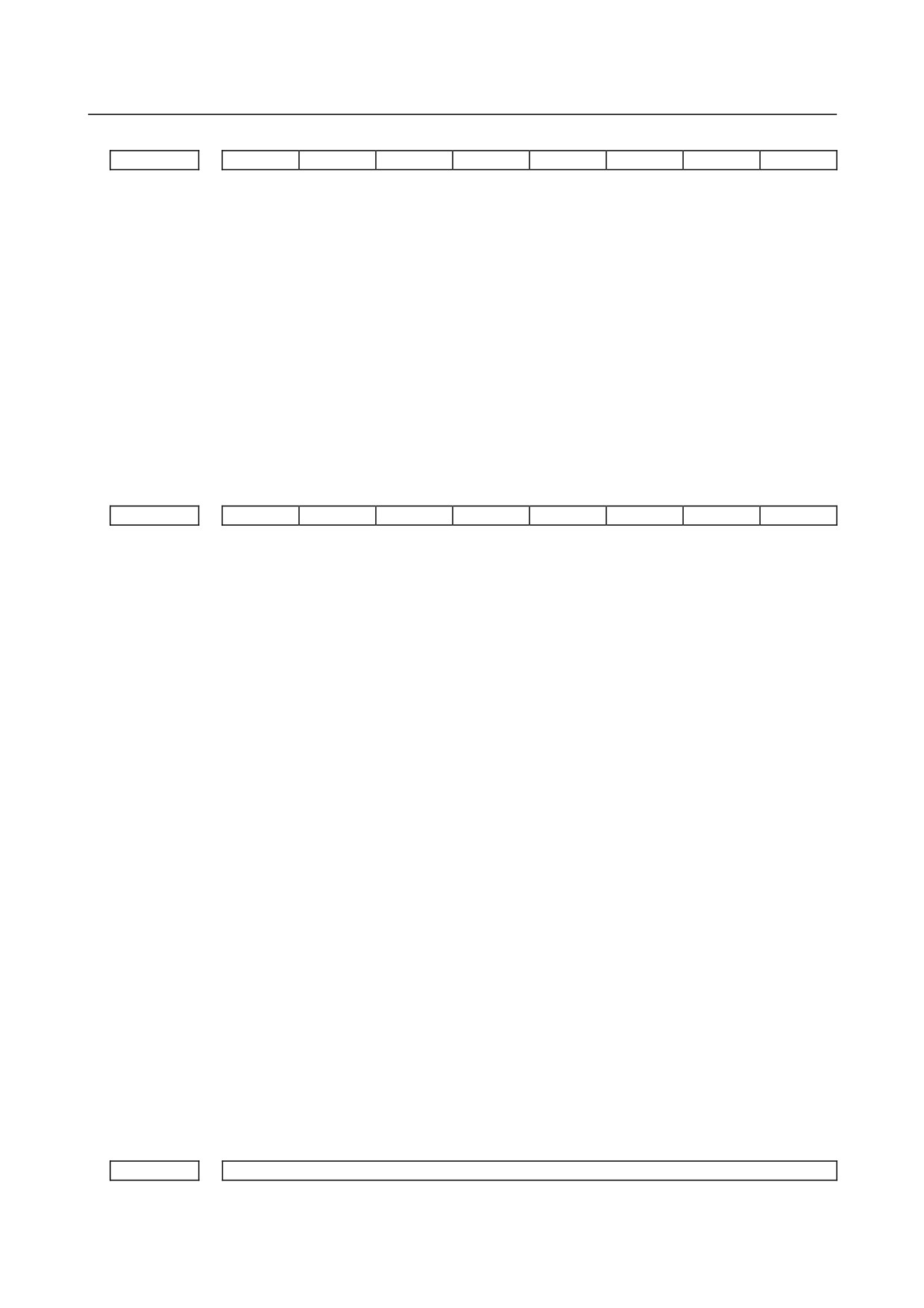
#7
#6
#5
#4
#3
#2
#1
#0
3195
EKE
HDE
HKE
[Input type] Parameter input
[Data type] Bit
#5 HKE A key operation history is:
0: Recorded.
1: Not recorded.
#6 HDE A DI/DO history is:
0: Recorded.
1: Not recorded.
#7 EKE The contents of operation history and alarm history
0: cannot be deleted.
1: can be deleted.
#7
#6
#5
#4
#3
#2
#1
#0
3196
HAL
HOM
HMV
HPM
HWO
HTO
[Data type] Bit
#0 HTO A modification history of tool offset data is:
0: Not recorded.
1: Recorded.
#1 HWO A modification history of workpiece offset
data/extended
workpiece offset
data/workpiece shift (T series) is:
0: Not recorded.
1: Recorded.
#2 HPM A modification history of parameters is:
0: Not recorded.
1: Recorded.
#3 HMV A modification history of custom macro common variables is:
0: Not recorded.
1: Recorded.
#6 HOM A history of external operator messages and macro messages (#3006) is:
0: Recorded.
1: Not recorded.
#7 HAL When an alarm is issued, additional information (modal data, absolute coordinates, and
machine coordinates present at the issuance of the alarm) is:
0: Recorded in the operation history and alarm history.
1: Not recorded in the operation history and alarm history.
To record as many alarm history items as possible, rather than detailed alarm information,
set 1. The numbers of ten G code modal groups to be recorded are set in parameter Nos.
12990 to 12999.
12990
(1st) G code modal group to be recorded in the history when an alarm is issued
[Input type] Parameter input
- 664 -

B-64304EN/02
OPERATION 12.SETTING AND DISPLAYING DATA
[Data type] Byte path
[Valid data range] 1 to the maximum number of G code groups
Set the number of a G code modal group to be recorded in the alarm history and operation
history when an alarm is issued.
* If a value beyond the valid data range is set, the status of group 01 is recorded.
12991
(2nd) G code modal group to be recorded in the history when an alarm is issued
[Input type] Parameter input
[Data type] Byte path
[Valid data range] 1 to the maximum number of G code groups
Set the number of a G code modal group to be recorded in the alarm history and operation
history when an alarm is issued.
* If a value beyond the valid data range is set, the status of group 02 is recorded.
12992
(3rd) G code modal group to be recorded in the history when an alarm is issued
[Input type] Parameter input
[Data type] Byte path
[Valid data range] 1 to the maximum number of G code groups
Set the number of a G code modal group to be recorded in the alarm history and operation
history when an alarm is issued.
* If a value beyond the valid data range is set, the status of group 03 is recorded.
12993
(4th) G code modal group to be recorded in the history when an alarm is issued
[Input type] Parameter input
[Data type] Byte path
[Valid data range] 1 to the maximum number of G code groups
Set the number of a G code modal group to be recorded in the alarm history and operation
history when an alarm is issued.
* If a value beyond the valid data range is set, the status of group 04 is recorded.
12994
(5th) G code modal group to be recorded in the history when an alarm is issued
[Input type] Parameter input
[Data type] Byte path
[Valid data range] 1 to the maximum number of G code groups
Set the number of a G code modal group to be recorded in the alarm history and operation
history when an alarm is issued.
* If a value beyond the valid data range is set, the status of group 05 is recorded.
12995
(6th) G code modal group to be recorded in the history when an alarm is issued
[Input type] Parameter input
[Data type] Byte path
[Valid data range] 1 to the maximum number of G code groups
Set the number of a G code modal group to be recorded in the alarm history and operation
history when an alarm is issued.
* If a value beyond the valid data range is set, the status of group 06 is recorded.
- 665 -