FANUC Series 0i-MODEL D, Series 0i Mate-MODEL D. OPERATOR'S MANUAL - page 12
1.GENERAL
OPERATION
B-64304EN/02
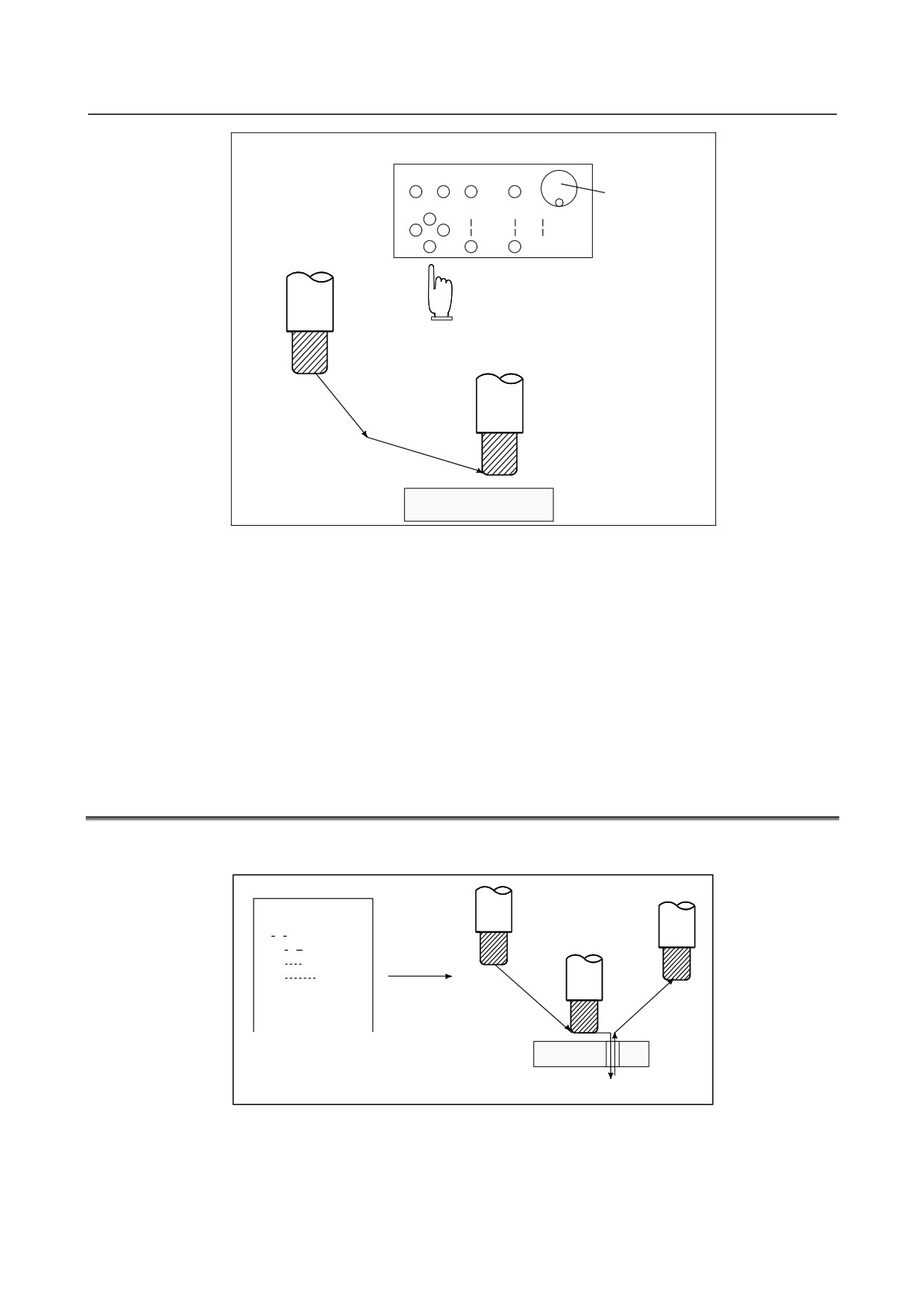
Machine operator's panel
Manual pulse
generator
Tool
Workpiece
Fig. 1.1 (b) The tool movement by manual operation
The tool can be moved in the following ways:
(i)
Jog feed (See Section III-3.2)
The tool moves continuously while a pushbutton remains pressed.
(ii) Incremental feed (See Section III-3.3)
The tool moves by the predetermined distance each time a button is pressed.
(iii) Manual handle feed (See Section III-3.4)
By rotating the manual handle, the tool moves by the distance corresponding to the degree of handle
rotation.
1.2
TOOL MOVEMENT BY PROGRAMING - AUTOMATIC
OPERATION
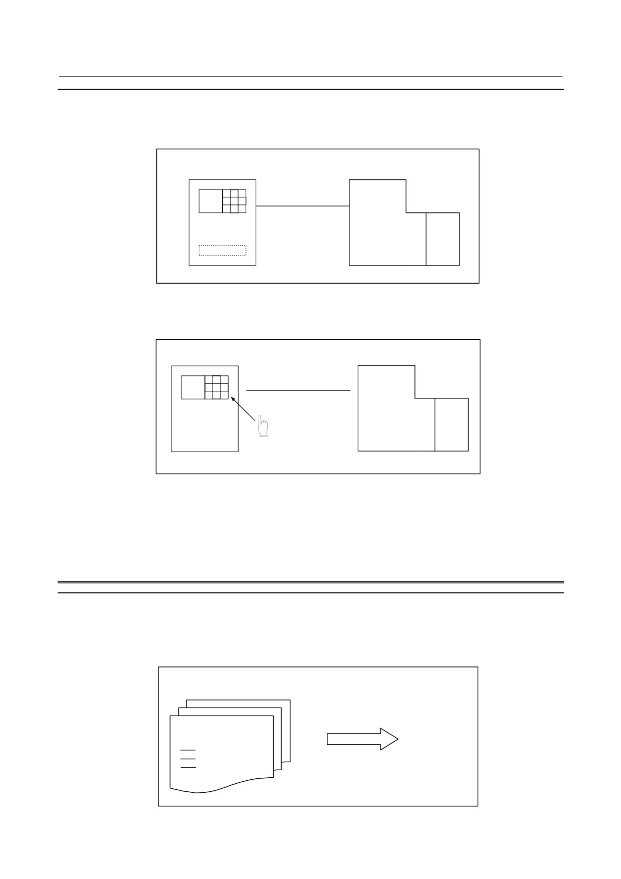
Automatic operation is to operate the machine according to the created program. It includes memory,
MDI and DNC operations. (See Section III-4).
Program
01000 ;
M S T ;
G92 X
;
Tool
G00
;
G01
;
:
:
:
Fig. 1.2 (a) Tool Movement by programming
- 306 -
B-64304EN/02
OPERATION
1.GENERAL
Explanation
-
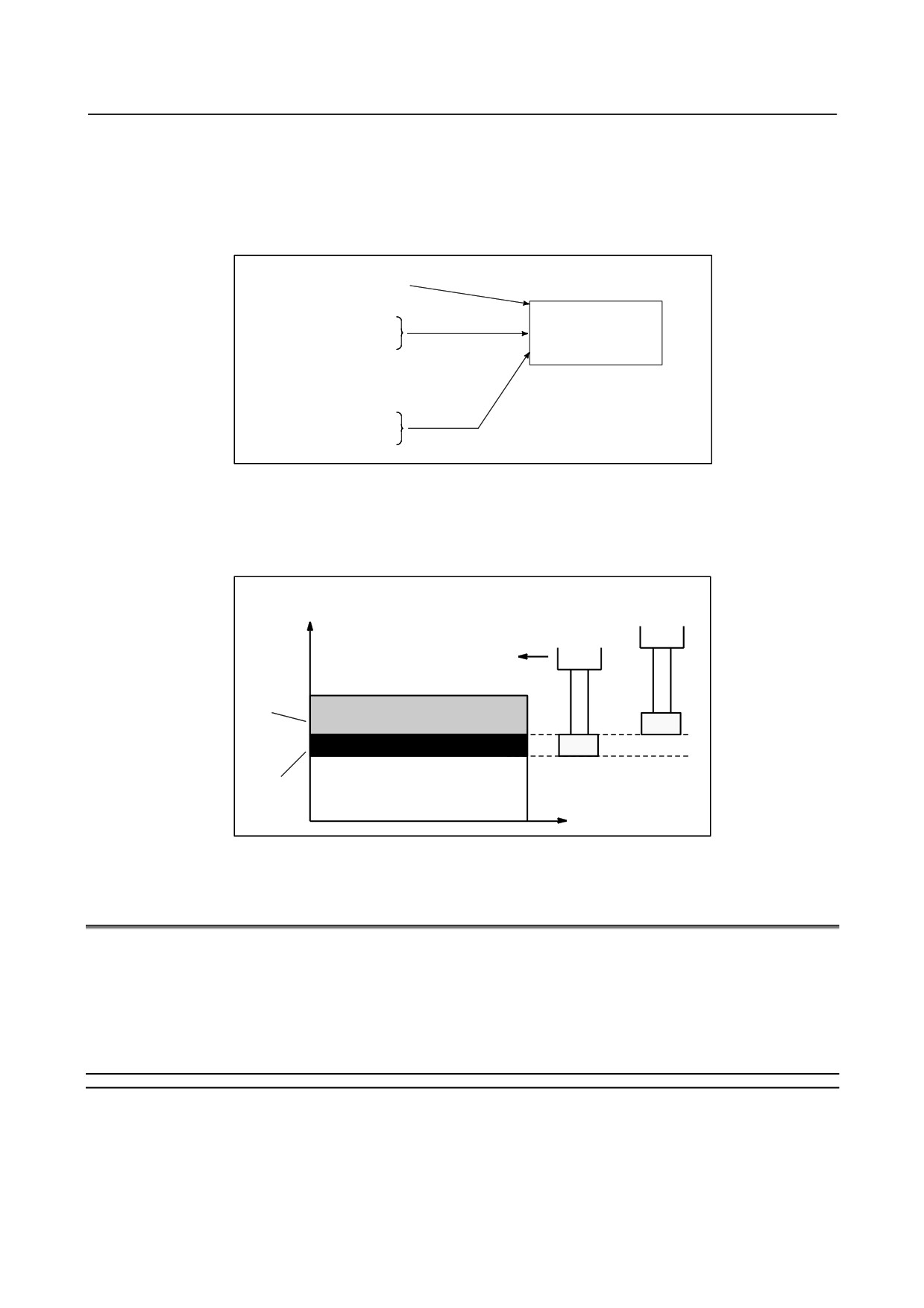
Memory operation
After the program is once registered in memory of CNC, the machine can be run according to the
program instructions. This operation is called memory operation.
CNC
Machine
Memory
Fig. 1.2 (b) Memory operation
-
MDI operation
After the program is entered, as an command group, from the MDI keyboard, the machine can be run
according to the program. This operation is called MDI operation.
CNC MDI keyboard
Machine
Manual program
input
Fig. 1.2 (c) MDI operation
-
DNC operation
In this mode of operation, the program is not registered in the CNC memory. It is read from the external
input/output devices instead. This is called DNC operation.
1.3
AUTOMATIC OPERATION
Explanation
-
Program selection
Select the program used for the workpiece. Ordinarily, one program is prepared for one workpiece. If
two or more programs are in memory, select the program to be used, by searching the program number
(Section III-9.3).
Programs in memory
O1001
Automatic
G92
operation
Search for desired program by
M30
file name or program number.
Fig. 1.3 (a) Program selection for automatic operation
- 307 -
1.GENERAL
OPERATION
B-64304EN/02
-
Start and stop
Pressing the cycle start pushbutton causes automatic operation to start. By pressing the feed hold or reset
pushbutton, automatic operation pauses or stops. By specifying the program stop or program termination
command in the program, the running will stop during automatic operation. When one process machining
is completed, automatic operation stops. (See Section III-4)
Cycle start
Start
Feed hold
Stop
Automatic
Reset
operation
Stop caused
by program
Program stop
Program end
Fig. 1.3 (b) Start and stop for automatic operation
-
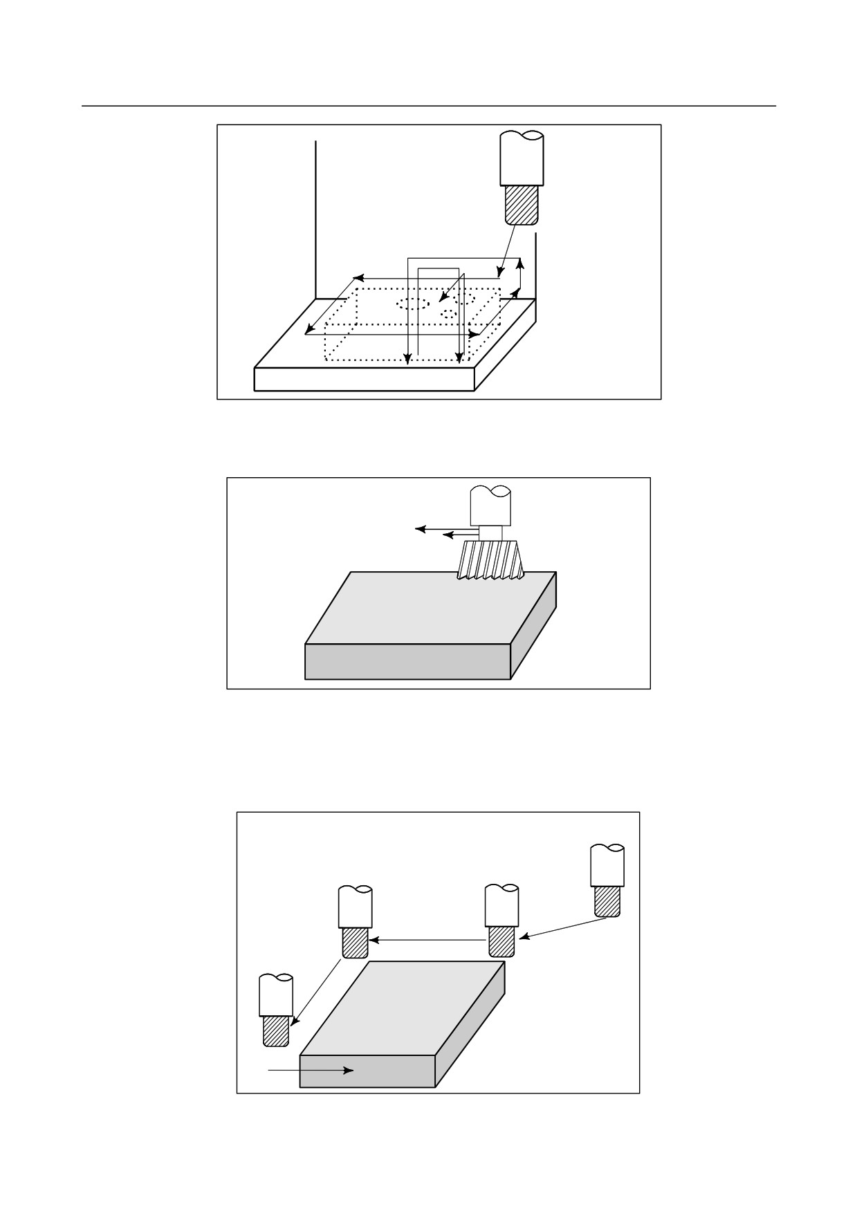
Handle interruption
While automatic operation is being executed, tool movement can overlap automatic operation by rotating
the manual handle. (See Section III-4.6)
Tool position
during automatic
Z
Tool position after
operation
handle interruption
Programmed
depth of cut
Depth of cut
by handle
interruption
X
Fig. 1.3 (c) Handle interruption for automatic operation
1.4
TESTING A PROGRAM
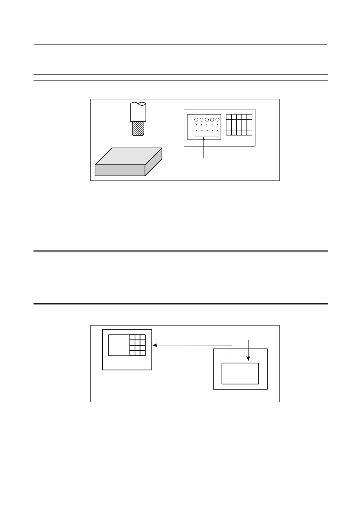
Before machining is started, the automatic running check can be executed.
It checks whether the created program can operate the machine as desired.
This check can be accomplished by running the machine actually or viewing the position display change
(without running the machine) (See Section III-5).
1.4.1
Check by Running the Machine
Explanation
-
Dry run
Remove the workpiece, check only movement of the tool. Select the tool movement rate using the dial on
the operator's panel. (See Section III-5.4)
- 308 -
B-64304EN/02
OPERATION
1.GENERAL
Tool
Table
Fig. 1.4.1 (a) Dry run
-
Feedrate override
Check the program by changing the feedrate specified in the program. (See Section III-5.2)
Feedrate specified by program :
100 mm/min.
Tool
Feedrate after feed rate
override (20%) : 20 mm/min.
Workpiece
Fig. 1.4.1 (b) Feedrate override
-
Single block
When the cycle start pushbutton is pressed, the tool executes one operation then stops. By pressing the
cycle start again, the tool executes the next operation then stops. The program is checked in this manner.
(See Section III-5.5)
Cycle
start
Cycle
Cycle
start
start
Tool
Cycle start
Stop
Stop
Workpiece
Stop
Fig. 1.4.1 (c) Single Block
- 309 -
1.GENERAL
OPERATION
B-64304EN/02
1.4.2
How to View the Current Position Display Change without
Running the Machine
Explanation
-
Machine Lock
MDI
X
Tool
Y
Z
Workpiece
The tool remains stopped, and only the
positional displays of the axes change.
Fig. 1.4.2 (a) Machine Lock
-
Auxiliary function lock
When automatic running is placed into the auxiliary function lock mode during the machine lock mode
(See Sections III-5.1), all auxiliary functions (spindle rotation, tool replacement, coolant on/off, etc.) (See
Section III-5.1) are disabled.
1.5
EDITING A PROGRAM
After a created program is once registered in memory, it can be corrected or modified from the MDI panel
(See Section III-10).
This operation can be executed using the program edit function.
1.6
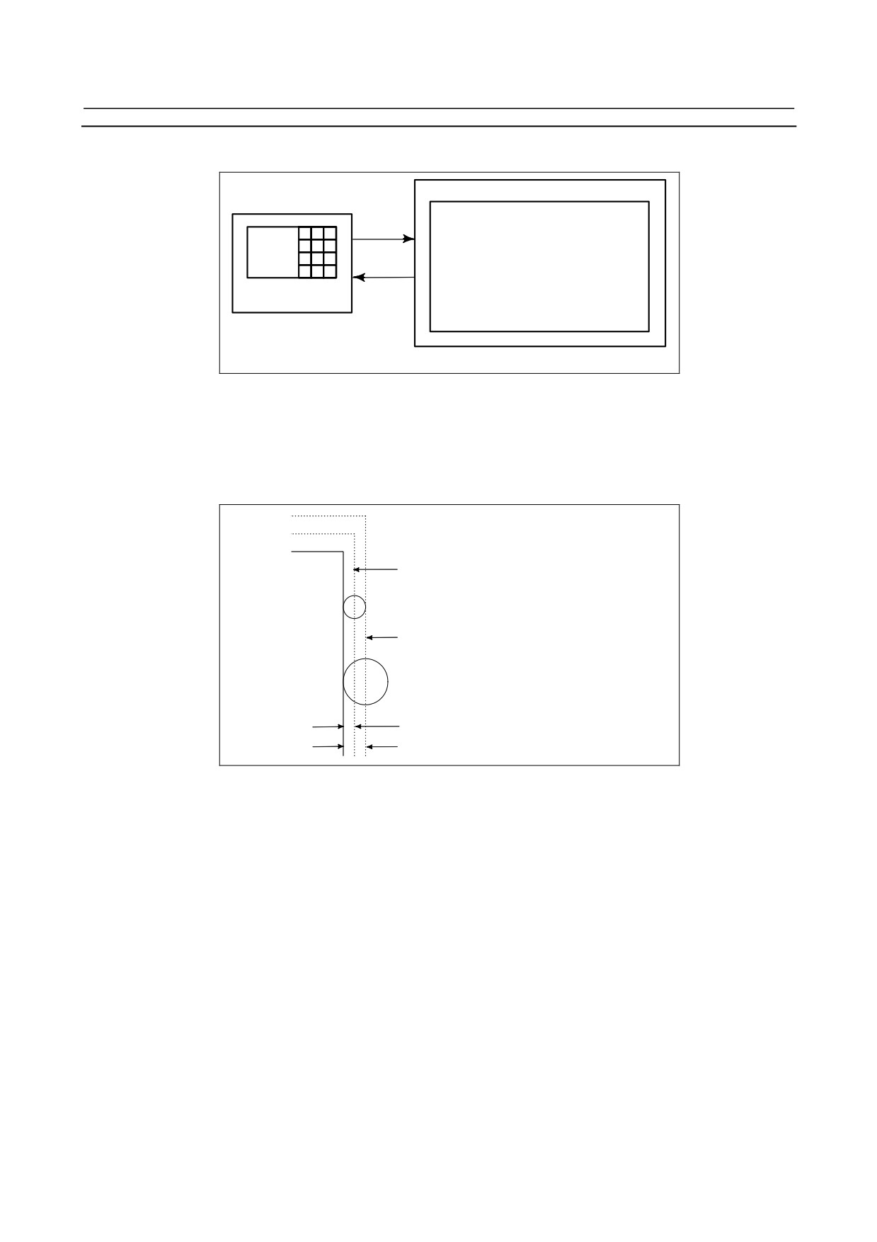
DISPLAYING AND SETTING DATA
The operator can display or change a value stored in CNC internal memory by key operation on the MDI
screen (See III-12).
Data setting
Data display
Screen Keys
MDI
CNC memory
Fig. 1.6 (a) Displaying and setting data
- 310 -
B-64304EN/02
OPERATION
1.GENERAL
Explanation
-
Offset value
Geometry
Wear
compensation compensation
Setting
Tool compensation number 1
12.3
25.0
Tool compensation number 2
20.0
40.0
Tool compensation number 3
Screen Keys
Display
MDI
CNC memory
Fig. 1.6 (b) Displaying and Setting Offset Values
The tool has the tool dimension (length, diameter). When a workpiece is machined, the tool movement
value depends on the tool dimensions.
By setting tool dimension data in CNC memory beforehand, CNC automatically generates tool routes that
permit any tool to cut the workpiece specified by the program. Tool dimension data is called the offset
value.
1st tool path
Machined
shape
2nd tool path
Offset value of the 1st tool
Offset value of the 2nd tool
Fig. 1.6 (c) Offset value
-
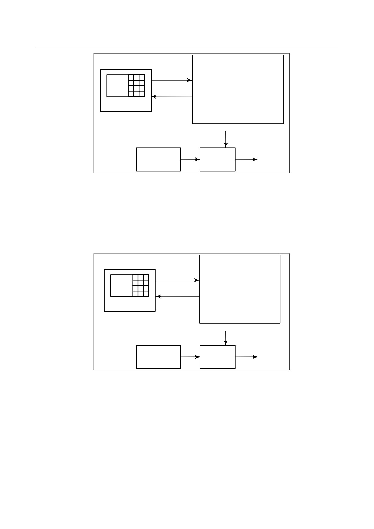
Displaying and setting operator's setting data
Apart from parameters, there is data that is set by the operator in operation. This data causes machine
characteristics to change.
For example, the following data can be set:
• Inch/Metric switching
• Selection of I/O devices
• Mirror image cutting on/off
The above data is called setting data (See Section III-12.3.1).
- 311 -
1.GENERAL
OPERATION
B-64304EN/02
Setting data
Inch/Metric switching
Setting
Selection of I/O device
Mirror image ON/OFF setting
:
:
Screen Keys
Displaying
:
MDI
CNC Memory
Operational
characteristics
Automatic
Movement of
Program
operation
the machine
Fig. 1.6 (d) Displaying and setting operator's setting data
-
Displaying and setting parameters
The CNC functions have versatility in order to take action in characteristics of various machines.
For example, CNC can specify the following:
-
Rapid traverse rate of each axis
-
Whether increment system is based on metric system or inch system.
-
How to set command multiply/detect multiply (CMR/DMR)
Data to make the above specification is called parameters (See Section III-12.4.1).
Parameters differ depending on machine tool.
Parameter
Rapid traverse rate
Setting
Position control
Reference position return
Backlash compensation data
Pitch error compensation data
Screen Keys
Display
:
:
MDI
:
CNC memory
Operational
characteristics
Automatic
Movement of
Program
operation
the machine
Fig. 1.6 (e) Displaying and setting parameters
-
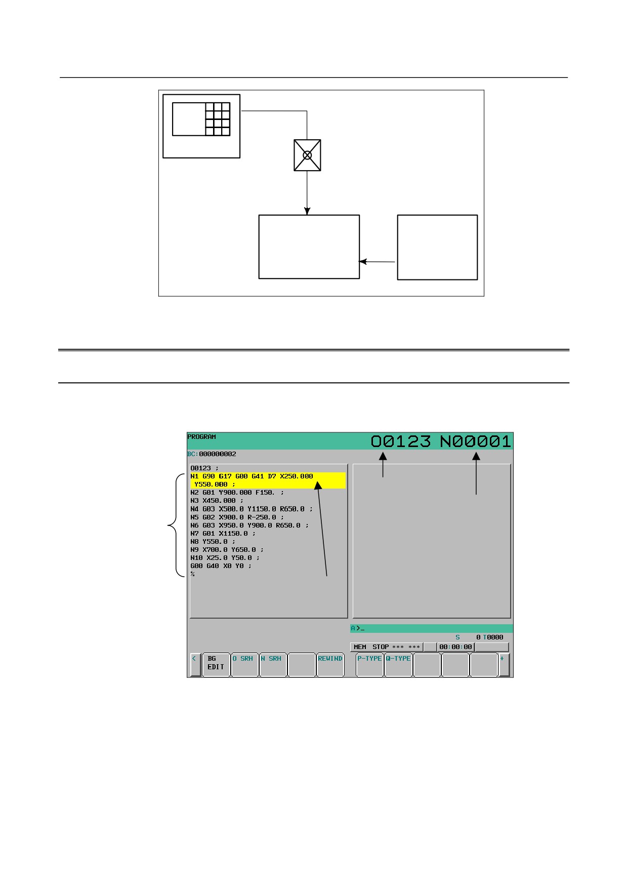
Data protection key
A key called the data protection key can be defined. It is used to prevent part programs, offset values,
parameters, and setting data from being registered, modified, or deleted erroneously (See Section III-12).
- 312 -
B-64304EN/02
OPERATION
1.GENERAL
Data Setting
Screen Keys
Data protection key
MDI
Registration / modification inhibition
Machine
operator's panel
Program
Offset value
Data protection key
Parameters
Signal
Setting data
CNC memory
Fig. 1.6 (f) Data protection key
1.7
DISPLAY
1.7.1
Program Display
The contents of the currently active program are displayed.
(See Section III-12.2.1)
Running program number
Running sequence number
Contents of program
The line currently being executed
is indicated by the cursor.
Fig. 1.7.1 (a)
- 313 -
1.GENERAL
OPERATION
B-64304EN/02
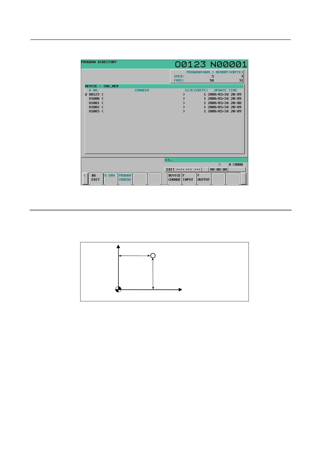
The programs in the program memory are listed.
Fig. 1.7.1 (b)
1.7.2
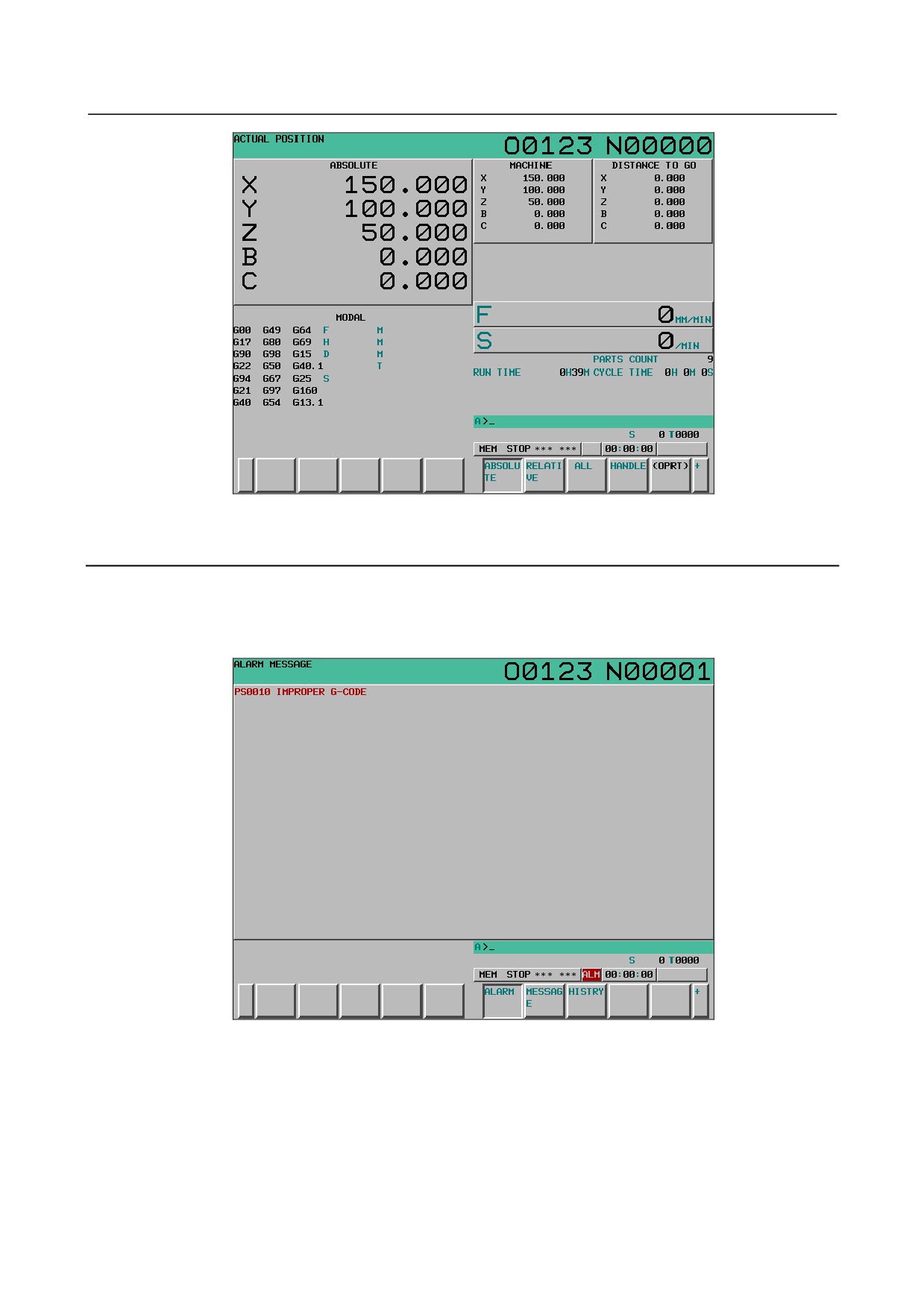
Current Position Display
The current position of the tool is displayed with the coordinate values.
Moreover, the distance from the current position to a target point can be displayed as a remaining travel
distance.
(See Subsections III-12.1.1 to 12.1.3.)
Y
X
Y
X
Workpiece coordinate system
Fig. 1.7.2 (a)
- 314 -
B-64304EN/02
OPERATION
1.GENERAL
Fig. 1.7.2 (b)
1.7.3
Alarm Display
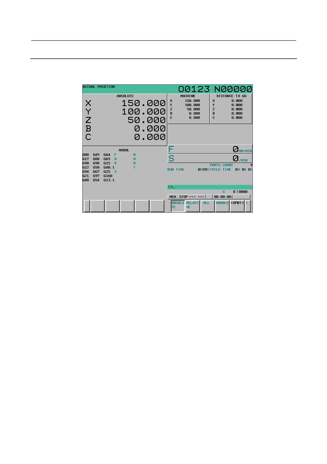
When a trouble occurs during operation, error code and alarm message are displayed on the screen. (See
Section III-7.1.)
See APPENDIX G for the list of error codes and their meanings.
Fig. 1.7.3 (a)
- 315 -
1.GENERAL
OPERATION
B-64304EN/02
1.7.4
Parts Count Display, Run Time Display
The position display screen displays a machined parts count, run time, and cycle time.
(See Section
lll-12.3.3.)
Fig. 1.7.4 (a)
- 316 -
B-64304EN/02
OPERATION
2.OPERATIONAL DEVICES
2 OPERATIONAL DEVICES
As operational devices, setting and display devices attached to the CNC, and machine operator's panels
are available.
For machine operator's panels, refer to the relevant manual of the machine tool builder.
Chapter 2, "OPERATIONAL DEVICES", consists of the following sections:
2.1 SETTING AND DISPLAY UNITS
317
2.2 OPERATIONAL DEVICES
322
2.3 FUNCTION KEYS AND SOFT KEYS
323
2.4 EXTERNAL I/O DEVICES
335
2.5 POWER ON/OFF
337
2.1
SETTING AND DISPLAY UNITS
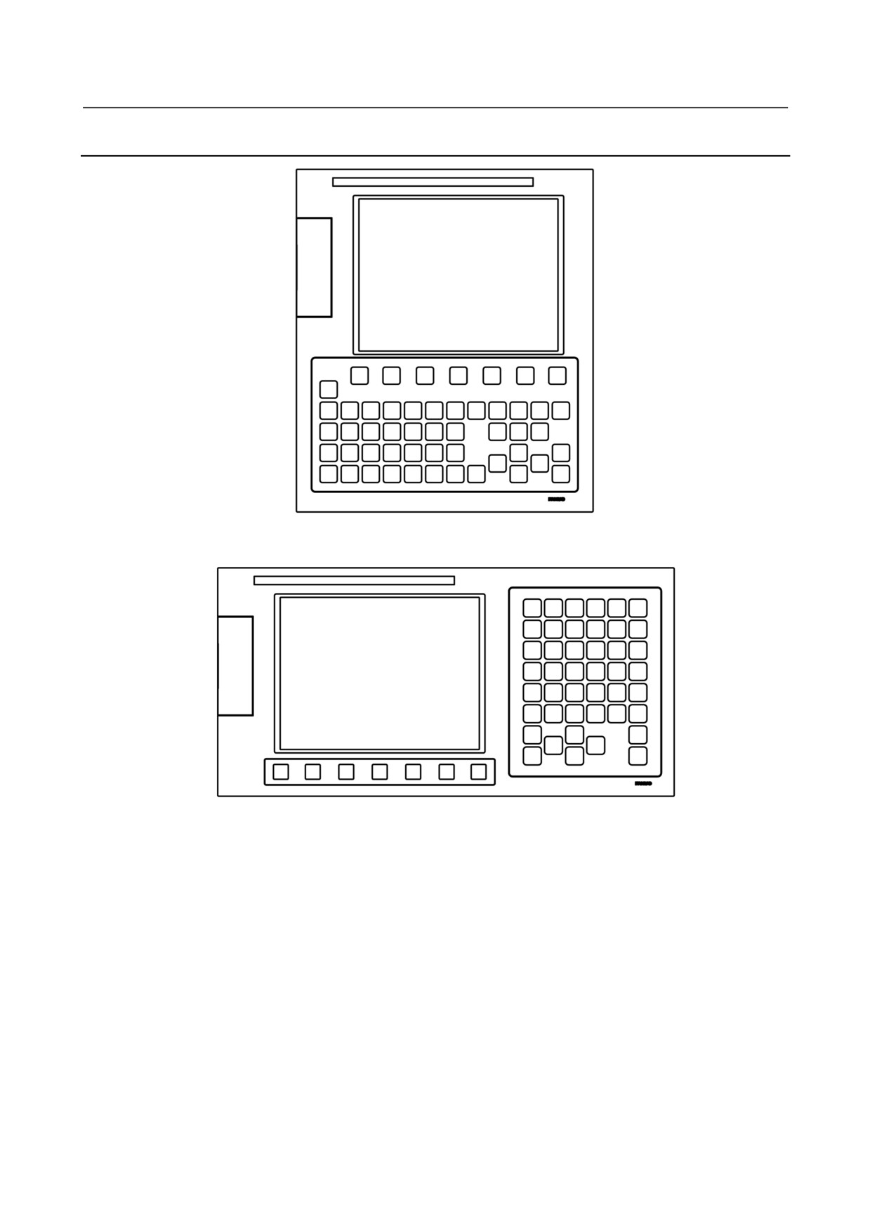
The setting and display units are shown in Subsections 2.1.1 to 2.1.4 of Part III.
8.4” LCD/MDIIII-2.1.1
10.4” LCD III-2.1.2
Standard MDI Unit (ONG Key)
III-2.1.3
Small MDI Unit (ONG Key)
III-2.1.4
- 317 -
2.OPERATIONAL DEVICES
OPERATION
B-64304EN/02
2.1.1
8.4” LCD/MDI
8.4” LCD/MDI (vertical type)
8.4” LCD/MDI (horizontal type)
- 318 -
B-64304EN/02
OPERATION
2.OPERATIONAL DEVICES
2.1.2
10.4” LCD
10.4” LCD
(Note) The touch panel display unit has no soft keys.
2.1.3
Standard MDI Unit (ONG Key)
-
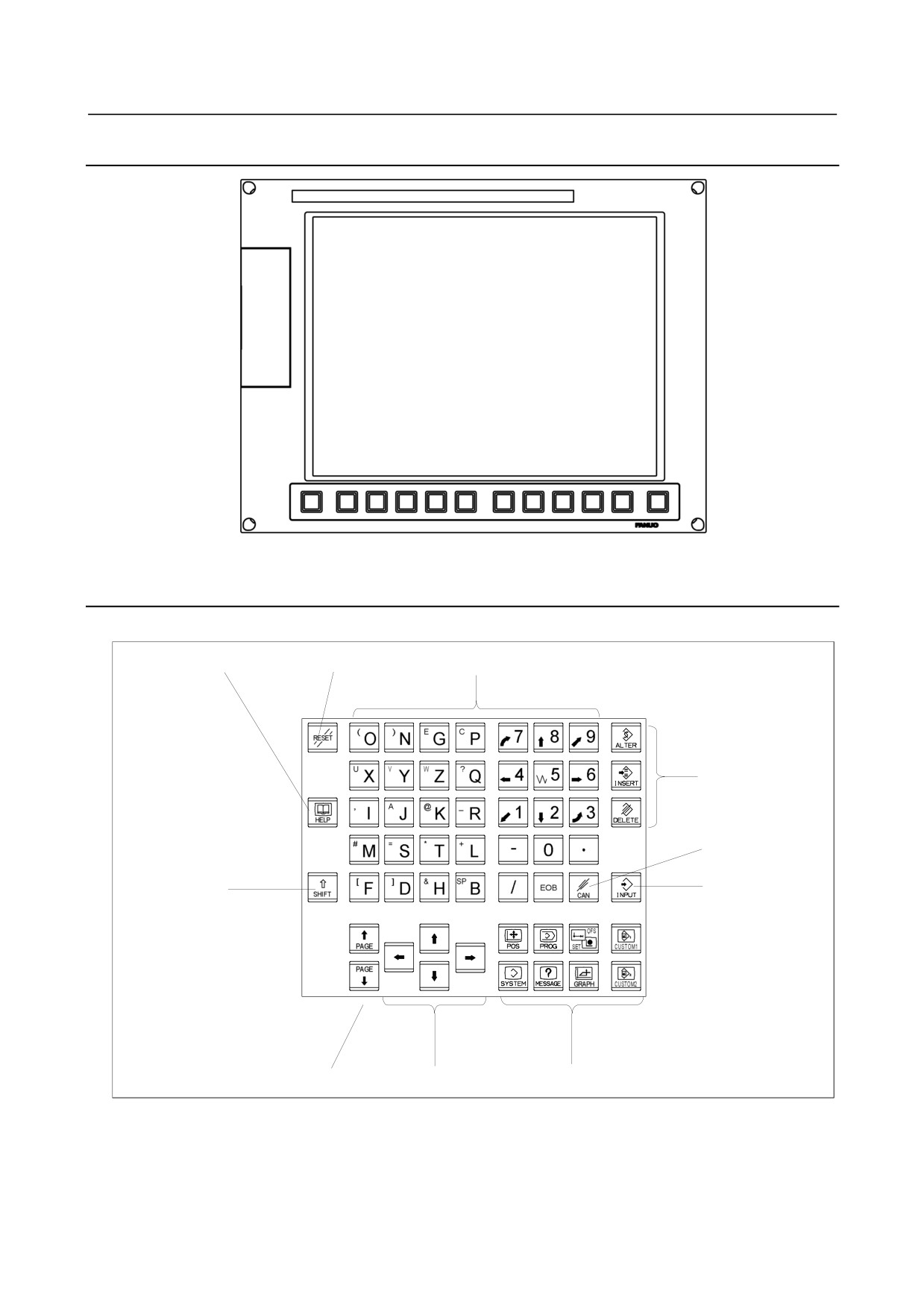
Unit with M series system
HELP key
RESET key
Address keys/Numeric keys
Edit keys
Cancel (CAN) key
SHIFT key
INPUT key
Page change keys
Cursor move keys
Function keys
- 319 -
2.OPERATIONAL DEVICES
OPERATION
B-64304EN/02
-
Unit with T series system
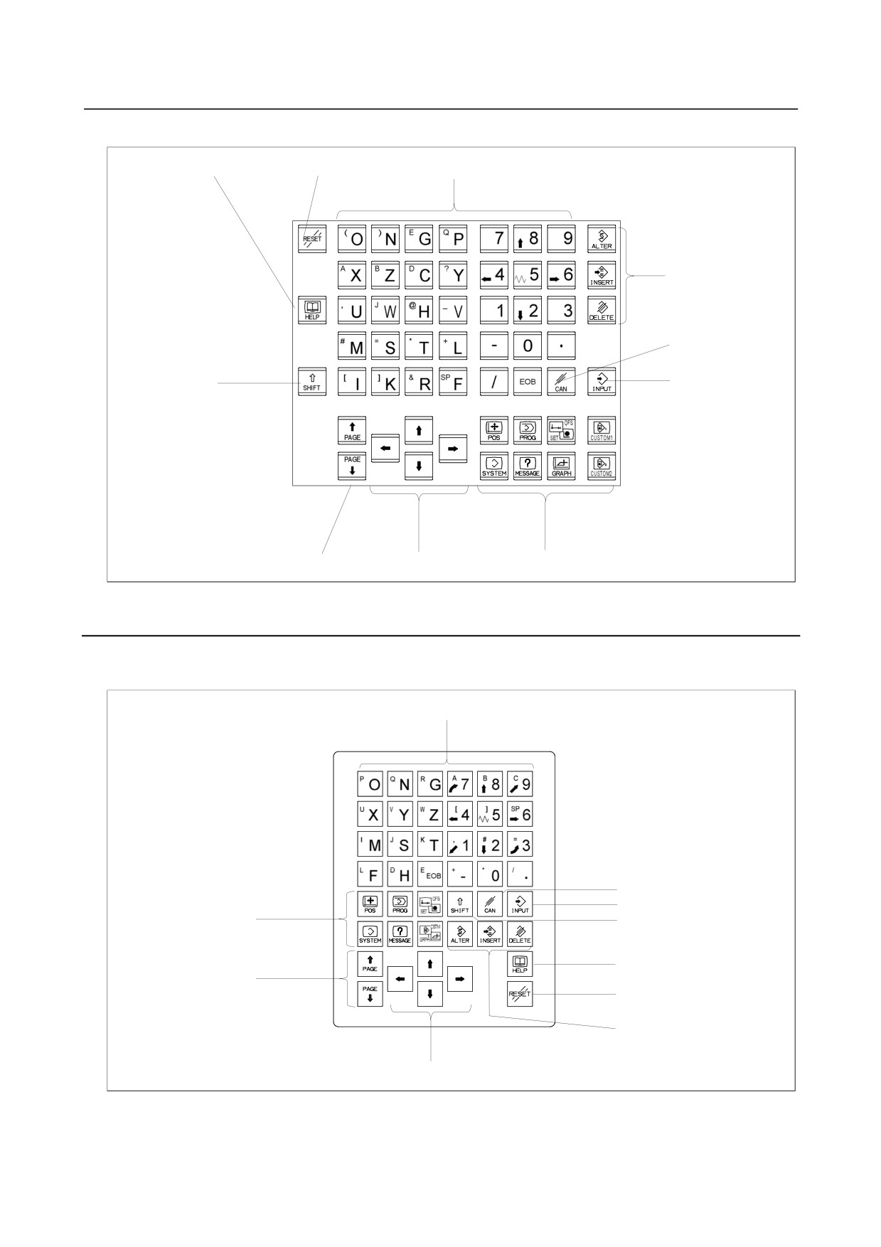
HELP key
RESET key
Address keys/Numeric keys
Edit keys
Cancel (CAN) key
SHIFT key
INPUT key
Page change keys
Cursor move keys
Function keys
2.1.4
Small MDI Unit (ONG Key)
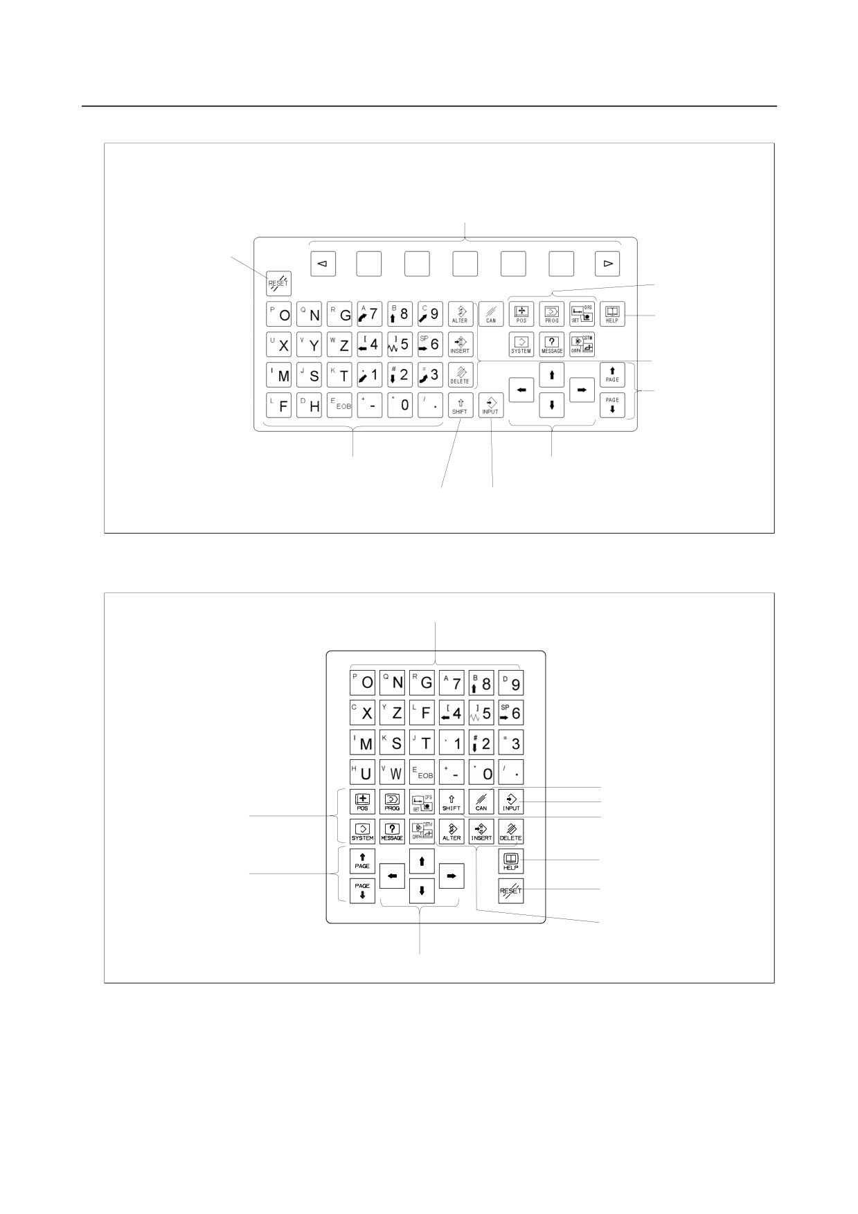
-
Unit with M series system
Small MDI unit (ONG Key, horizontal type)
Address keys/Numeric keys
Cancel (CAN) key
INPUT key
Function keys
SHIFT key
HELP key
Page change keys
RESET key
Edit keys
Cursor move keys
- 320 -
B-64304EN/02
OPERATION
2.OPERATIONAL DEVICES
Small MDI unit (ONG Key, vertical type)
Soft keys
RESET key
Function keys
HELP key
Edit keys
Page change keys
Address keys/Numeric keys
Cursor move keys
SHIFT key
INPUT key
-
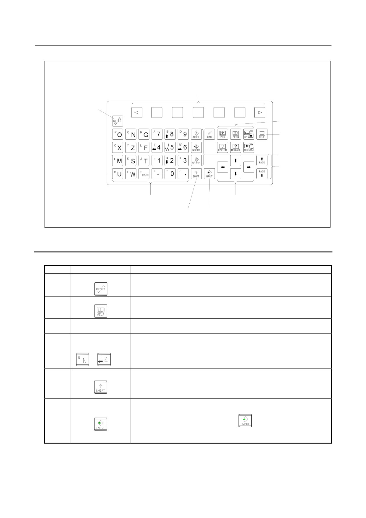
Unit with T series system
Small MDI unit (ONG Key, horizontal type)
Address keys/Numeric keys
Cancel (CAN) key
INPUT key
Function keys
SHIFT key
HELP key
Page change keys
RESET key
Edit keys
Cursor move keys
- 321 -
2.OPERATIONAL DEVICES
OPERATION
B-64304EN/02
Small MDI unit (ONG Key, vertical type)
Soft keys
RESET key
Function keys
HELP key
Edit keys
Page change keys
Address keys/Numeric keys
Cursor move keys
SHIFT key
INPUT key
2.2
OPERATIONAL DEVICES
Table 2.2 (a) Explanation of the MDI keyboard
Number
Name
Explanation
RESET key
1
Press this key to reset the CNC, to cancel an alarm, etc.
HELP key
Press this key to use the help function when uncertain about the operation
2
of an MDI key (help function).
The soft keys have various functions, according to the Applications. The soft key
3
Soft keys
functions are displayed on the display unit.
Address and numeric
keys
4
Press these keys to input alphabetic, numeric, and other characters.
Some address keys or numeric keys have two characters on their top faces.
SHIFT key
Pressing the <SHIFT> key switches the characters. Special character ^ is
5
displayed on the screen when a character indicated at the upper left corner on
the keytop can be entered.
When an address key or a numerical key is pressed, the data is input to the key
input buffer, and it is displayed on the screen. To copy the data in the key input
INPUT key
6
buffer to the offset register, etc., press the
key. This key is equivalent
to the [INPUT] key of the soft keys, and either can be pressed to produce the
same result.
- 322 -
B-64304EN/02
OPERATION
2.OPERATIONAL DEVICES
Number
Name
Explanation
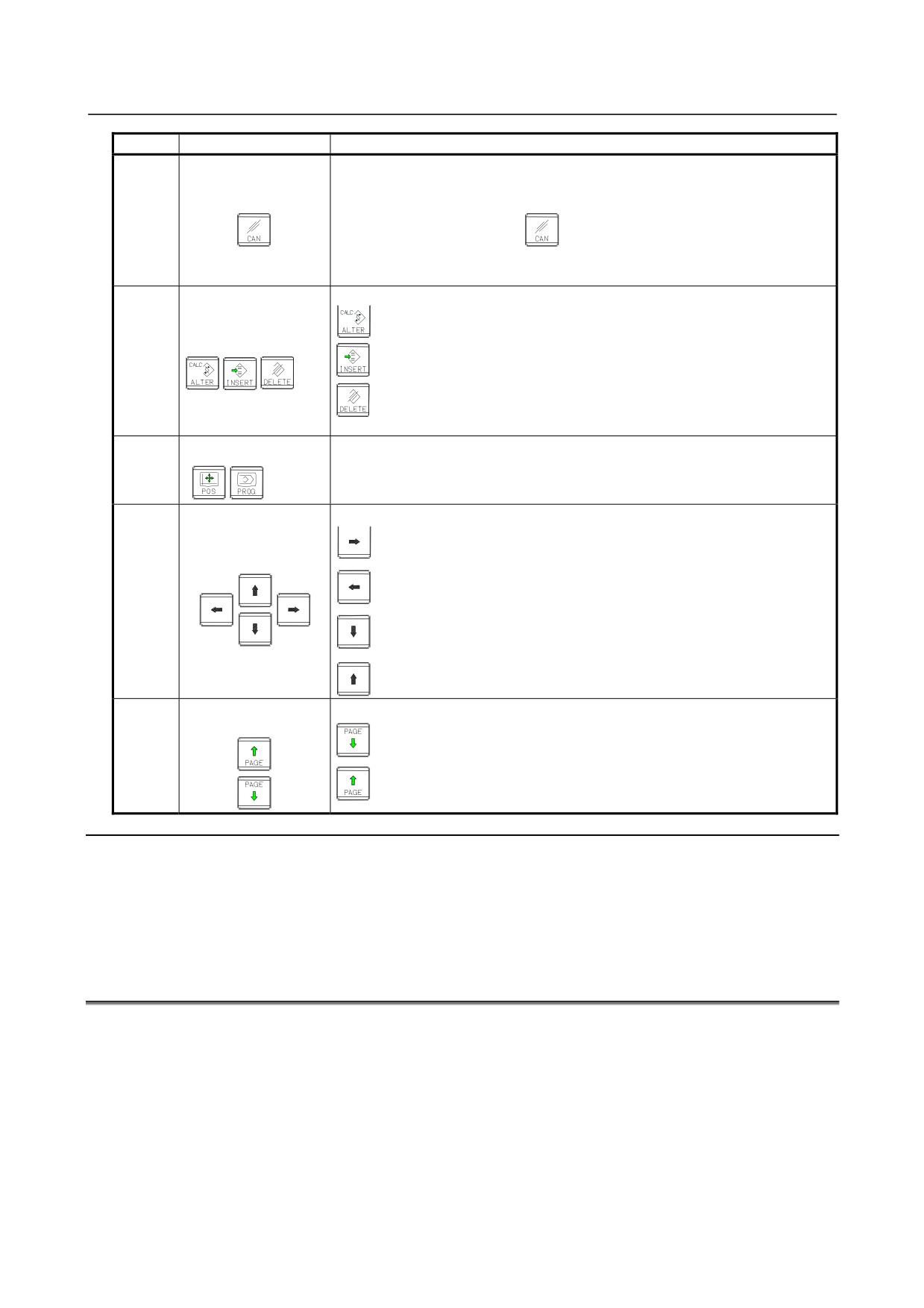
Press this key to delete the last character or symbol input to the key input buffer.
Example) When the key input buffer displays
CANCEL (CAN) key
>N001X100Z_
7
and the cancel key
is pressed, Z is canceled and
>N001X100_
is displayed.
Press these keys when editing the program.
: ALTER
Edit keys
: INSERT
8
: IDELETE
Function keys
Press theses keys to switch display screens for each function.
9
See lll-2.3 for details of the function keys.
There are four different cursor move keys.
: This key is used to move the cursor to the right or in the forward
Cursor keys
direction. The cursor is moved in short units in the forward direction.
: This key is used to move the cursor to the left or in the reverse direction.
10
The cursor is moved in short units in the reverse direction.
: This key is used to move the cursor in a downward or forward direction.
The cursor is moved in large units in the forward direction.
: This key is used to move the cursor in an upward or reverse direction.
The cursor is moved in large units in the reverse direction.
Page change keys
Two kinds of page change keys are described below.
(Page keys)
: This key is used to changeover the page on the screen in the forward
direction.
11
: This key is used to changeover the page on the screen in the reverse
direction.
Explanation
-
Key operation with 2-path control
In the 2-path control, be sure to select the tool post for which data is specified, using the path selection
switch on the machine operator's panel. Then, perform keyboard operation, such as displaying or
specifying various data items, and editing a program.
2.3
FUNCTION KEYS AND SOFT KEYS
The function keys are used to select the type of screen (function) to be displayed. When a soft key
(section select soft key) is pressed immediately after a function key, the screen (section) corresponding to
the selected function can be selected.
This section assumes the 8.4-inch display unit with seven soft keys.
- 323 -
2.OPERATIONAL DEVICES
OPERATION
B-64304EN/02
2.3.1
General Screen Operations
-
Procedure
1
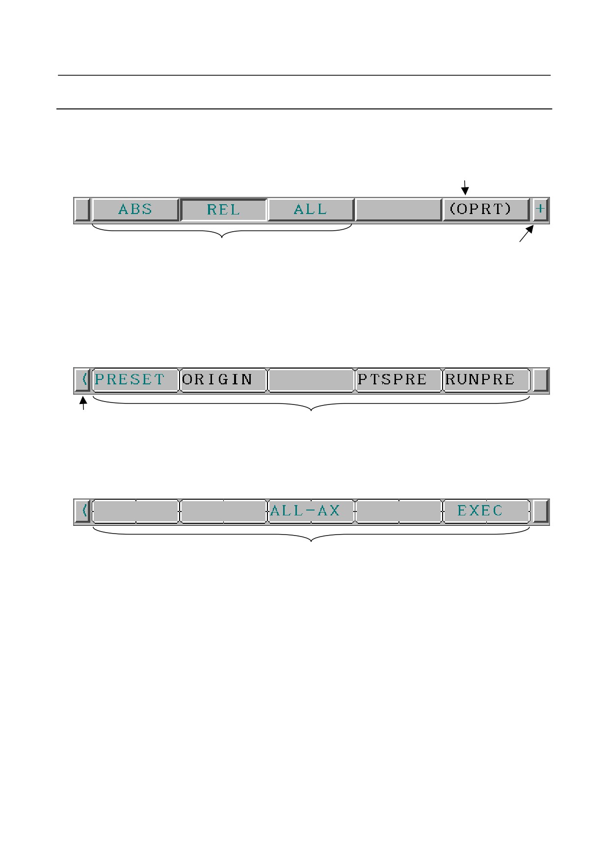
By pressing a function key on the MDI panel, the chapter selection soft keys that belong to the
function are displayed.
Example 1)
Operation selection key
Chapter selection soft keys
Continuous menu key
2
When one of the chapter selection soft keys is pressed, the screen of the chapter is displayed. If the
soft key of a desired chapter is not displayed, press the continuous menu key.
In a chapter, a further choice may be made from multiple chapters.
3
When the screen of a desired chapter is displayed, press the operation selection key to display
operations (operation selection soft keys). If address/numeric keys are used, operation selection
soft keys may be displayed automatically.
Example 2)
Return menu key
Operation selection soft keys
4
Select a desired operation with the operation selection soft key.
Depending on the operation to be executed, an auxiliary menu of soft keys is displayed. Perform
an operation according to the indications on the auxiliary menu.
Example 3)
Auxiliary menu
5
To return to the display of chapter selection soft keys, press the return menu key.
A general screen display procedure is provided above.
The actual display procedure varies from one screen to another.
For details, see each description of operation.
-
Button design change depending on soft key state
The soft keys to be displayed depend on the object to be selected.
• Chapter selection soft keys
• Operation selection soft keys
• Auxiliary menu of operation selection soft keys
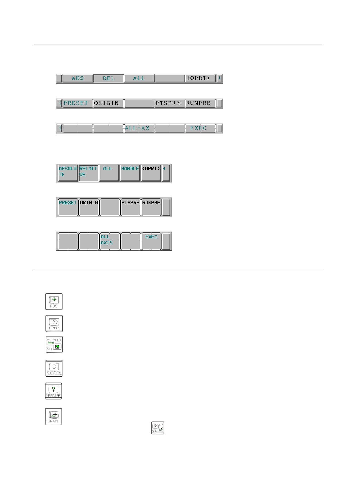
Depending on the state, the button images of the soft keys change.
From the button images, which state the soft keys are assuming can be known.
- 324 -
B-64304EN/02
OPERATION
2.OPERATIONAL DEVICES
Example 1)
For the 8.4-inch LCD display unit
Chapter selection soft keys
Operation selection soft keys
Operation selection keys, auxiliary menu
Example 2)
For the 10.4-inch LCD display unit
Chapter selection soft keys
Operation selection soft keys
Operation selection keys, auxiliary menu
2.3.2
Function Keys
Function keys are provided to select the type of screen to be displayed. The following function keys are
provided on the MDI panel:
Press this key to display the position screen.
Press this key to display the program screen.
Press this key to display the offset/setting screen.
Press this key to display the system screen.
Press this key to display the message screen.
Press this key to display the graphics screen.
For the small MDI unit, press
- 325 -
2.OPERATIONAL DEVICES
OPERATION
B-64304EN/02
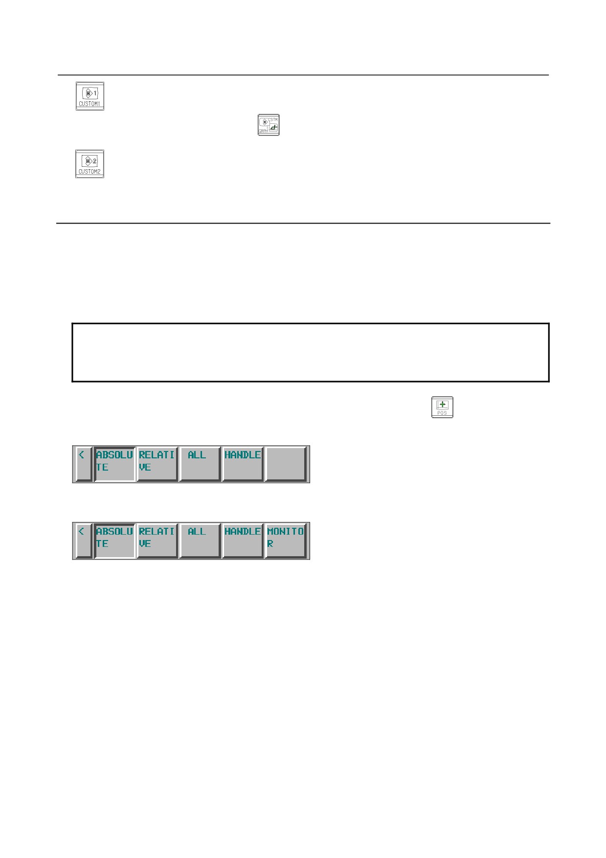
Press this key to display the custom screen 1 (conversational macro screen or C language
executor screen).
For the small MDI unit, press
Press this key to display the custom screen 2 (conversational macro screen or C language
executor screen).
For the small MDI unit, there is no key that corresponds to this key.
2.3.3
Soft Keys
By pressing a soft key after a function key, the corresponding screen of the function can be displayed.
The chapter selection soft keys of each function are described below.
The four keys on the right-hand side are assigned to chapter selection soft keys. When multiple pages
are used for chapter selection soft keys, [+] is displayed on the continuous menu key (rightmost soft key).
Press the continuous menu key to switch between chapter selection soft keys.
NOTE
1 Press function keys to switch between screens that are used frequently.
2 Some soft keys are not displayed depending on the option configuration or
parameter setting.
For the 10.4-inch LCD display unit, when pressing other than function key
indicates positional
display on the left side of the screen, the left half of the soft keys are shown below.
or
As for the soft key [MONITOR], refer to Section III-12.8.
Refer to the next page for other soft keys.
- 326 -
B-64304EN/02
OPERATION
2.OPERATIONAL DEVICES
Position display screen
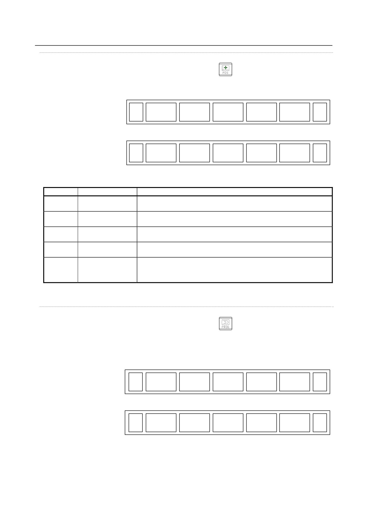
The chapter selection soft keys that belong to the function key
and the function of each screen are
described below.
(1)
(2)
(3)
(4)
(5)
ABS
REL
ALL
HNDL
(OPRT)
+
Page 1
(6)
(7)
(8)
(9)
(10)
MONI
(OPRT)
+
Page 2
Table 2.3.3 (a) Position display screen
No.
Chapter menu
Description
(1)
ABS
Selects the absolute coordinate display screen.
(ABSOLUTE)
(2)
REL
Selects the relative coordinate display screen.
(RELATIVE)
(3)
ALL
Selects the overall coordinate display screen.
(ALL)
(4)
HNDL
Selects the operation screen for manual handle operation.
(HANDLE)
(6)
MONI
Selects the screen for displaying the servo axis load meter, serial spindle load
(MONITOR)
meter, and speedometer.
* The items enclosed by parentheses on the second line under "Chapter menu" are displayed in the
10.4-inch display unit.
Program screen
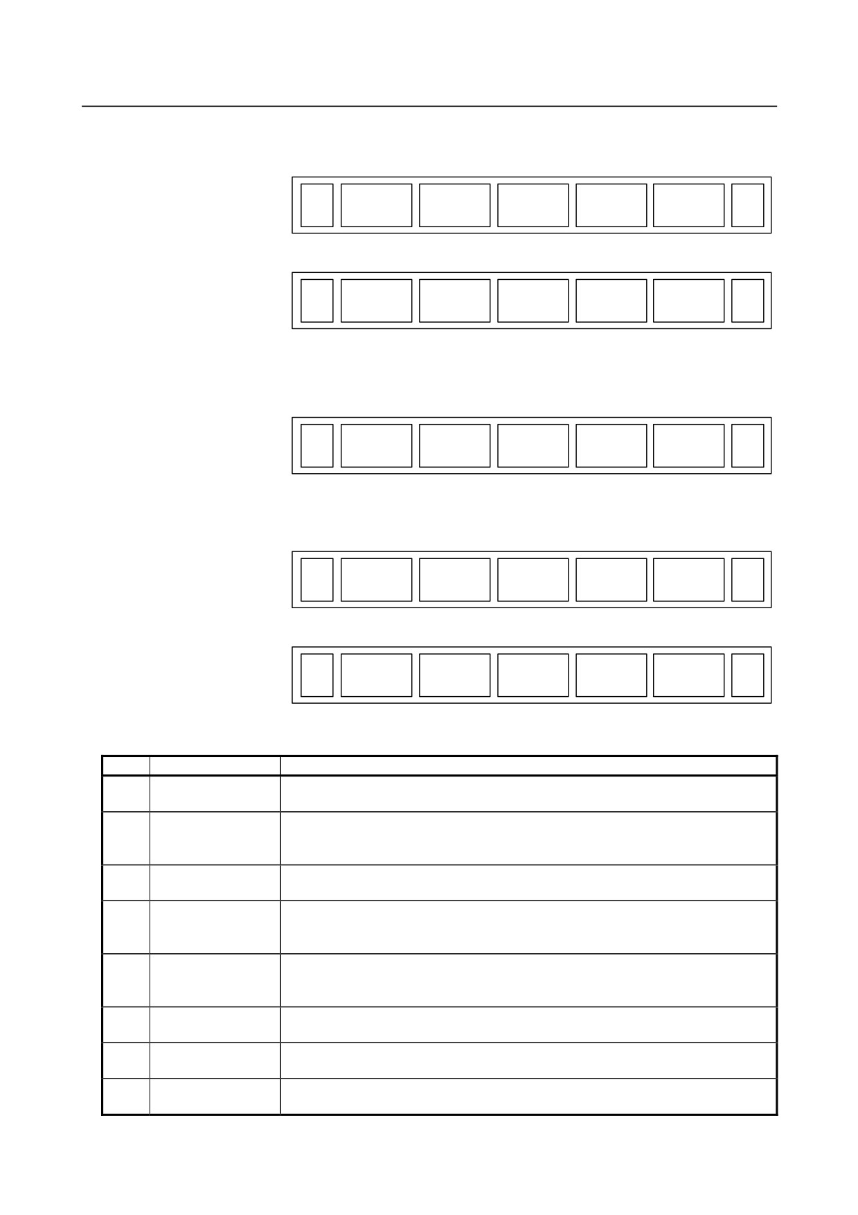
The chapter selection soft keys that belong to the function key
and the function of each screen are
described below.
In the MEM/RMT mode
(1)
(2)
(3)
(4)
(5)
PROGRM
CHECK
CURRENT
NEXT
(OPRT)
+
Page 1
(6)
(7)
(8)
(9)
(10)
RESTART
DIR
(OPRT)
+
Page 2
- 327 -
2.OPERATIONAL DEVICES
OPERATION
B-64304EN/02
In the MDI mode
(1)
(2)
(3)
(4)
(5)
PROGRM
MDI
CURRENT
NEXT
(OPRT)
+
Page 1
(6)
(7)
(8)
(9)
(10)
RESTART
DIR
(OPRT)
+
Page 2
In the EDIT/TJOG/THND mode
(1)
(2)
(3)
(4)
(5)
PROGRM
DIR
C.A.P
(OPRT)
+
Page 1
In the JOG/HND/REF mode
(1)
(2)
(3)
(4)
(5)
PROGRM
CURRENT
NEXT
(OPRT)
+
Page 1
(6)
(7)
(8)
(9)
(10)
RESTART
DIR
(OPRT)
+
Page 2
Table 2.3.3 (b) Program
No.
Chapter menu
Description
(1)
PROGRM
Selects the screen for displaying a list of part programs currently registered.
(PROGRAM)
(2)
CHECK
Selects the program check screen for displaying program and axis positions and
modal command values.
(Only for the 8.4- or 10.4-inch display unit used for simultaneous 2-path displays)
(2)
MDI
Selects the screen for editing and displaying a program in the MDI mode. (Only in the
(MDI)
MDI mode)
(3)
CURRENT
Selects the screen for displaying the modal command value and the command value
of the block currently being executed from command values. (Only for the 8.4-inch
display unit)
(4)
NEXT
Selects the screen for displaying the command value of the block currently being
(NEXT BLOCK)
executed and the command value of the block to be executed next from command
values.
(4)
C.A.P
Selects the screen for figure conversational input or the screen of MANUAL GUIDE
(C.A.P)
0i.
(6)
RESTART
Selects the operation screen for restarting an interrupted program operation.
(RESTART)
(2)
DIR
Selects the screen for displaying a list of part programs currently registered.
(7)
(DIR)
- 328 -
B-64304EN/02
OPERATION
2.OPERATIONAL DEVICES
* The items enclosed by parentheses on the second line under "Chapter menu" are displayed in the
10.4-inch display unit.
Offset/setting screen
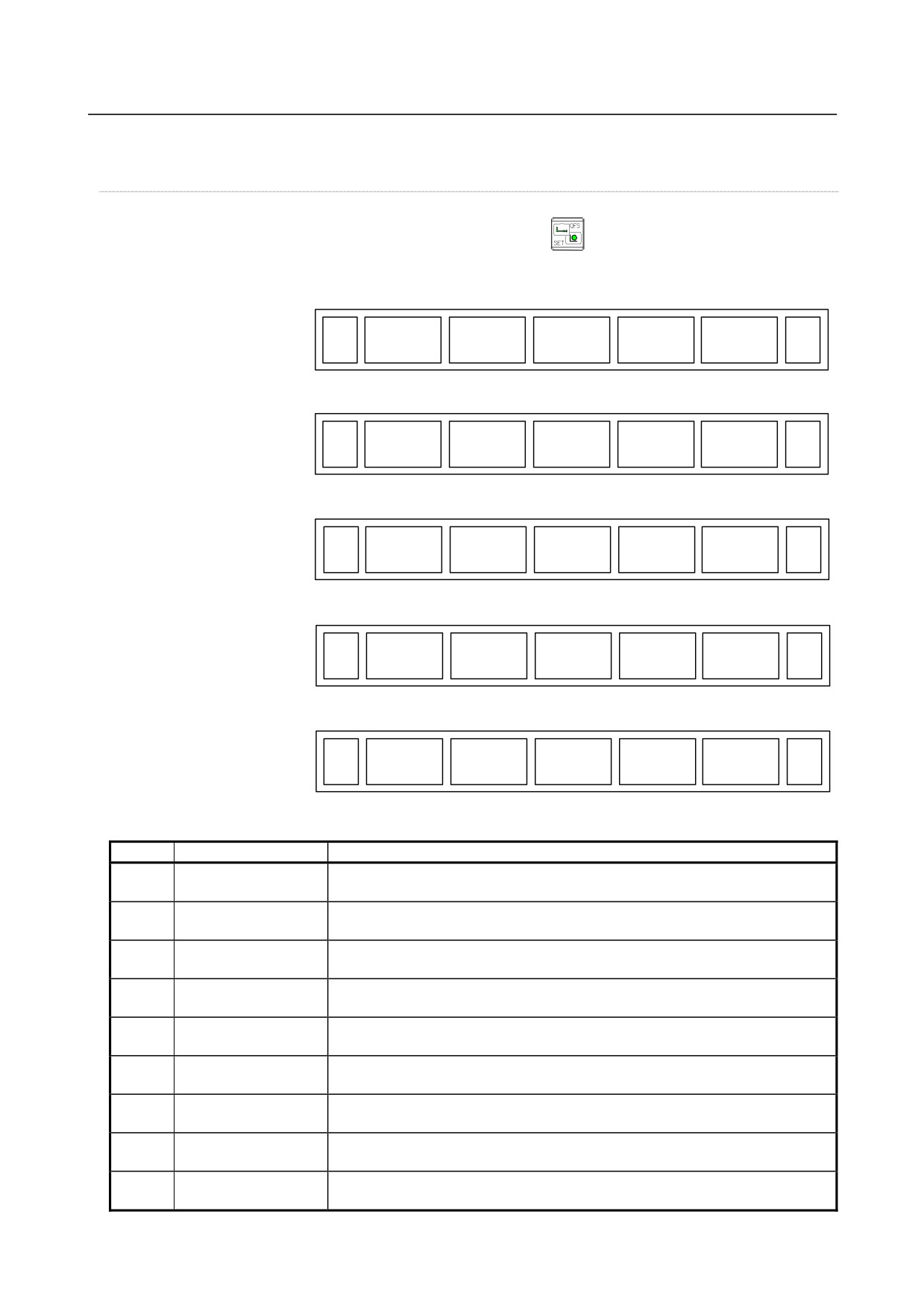
The chapter selection soft keys that belong to the function key
and the function of each screen are
described below.
(1)
(2)
(3)
(4)
(5)
OFFSET
SETTING
WORK
(OPRT)
+
Page 1
(6)
(7)
(8)
(9)
(10)
MACRO
MENU
OPR
TOOLLF
(OPRT)
+
Page 2
(11)
(12)
(13)
(14)
(15)
OFST.2
W.SHFT
BARRIER
(OPRT)
+
Page 3
(16)
(17)
(18)
(19)
(20)
PR-LEV
(OPRT)
+
Page 4
(21)
(22)
(23)
(24)
(25)
LANG.
PROT.
GUARD
(OPRT)
+
Page 5
Table 2.3.3 (c) Offset
No.
Chapter menu
Description
(1)
OFFSET
Selects the screen for setting tool offset values.
(OFFSET)
(2)
SETTING
Selects the screen for setting the setting parameters.
(SETTING)
(3)
WORK
Selects the screen for setting a workpiece coordinate system offset.
(WORK)
(6)
MACRO
Selects the screen for setting macro variables.
(MACRO)
(7)
MENU
Selects the screen for setting pattern data. (Pattern data input)
(PATTERN MENU)
(8)
OPR
Selects the screen for operating part of the operation switches on the machine
(OPERAT PANEL)
operator's panel as soft switches on the CNC screen. (Software operator's panel)
(9)
TOOLLF
Selects the screen for setting tool life data.
(TOOL LIFE)
(11)
OFST.2
Selects the screen for setting Y-axis offsets. (Only for the T series)
(Y OFFSET)
(12)
W.SHFT
Selects the screen for setting workpiece coordinate system shift values. (Only for
(WORK SHIFT)
the T series)
- 329 -
2.OPERATIONAL DEVICES
OPERATION
B-64304EN/02
No.
Chapter menu
Description
(14)
BARRIER
Selects the chuck tail stock barrier screen. (Only for the T series)
(BARRIER)
(17)
PR-LEV
Selects the screen for setting precision levels. (Machining condition selection
(PRECI LEVEL)
function)
(22)
LANG.
Selects the screen for setting a display language.
(LANGUAGE)
(23)
PROT.
Selects the screen for setting 8-level data protection.
(PROTECT)
(24)
GUARD
Selects the screen for setting wrong operation prevention.
(GUARD)
* The items enclosed by parentheses on the second line under "Chapter menu" are displayed in the
10.4-inch display unit.
System screen
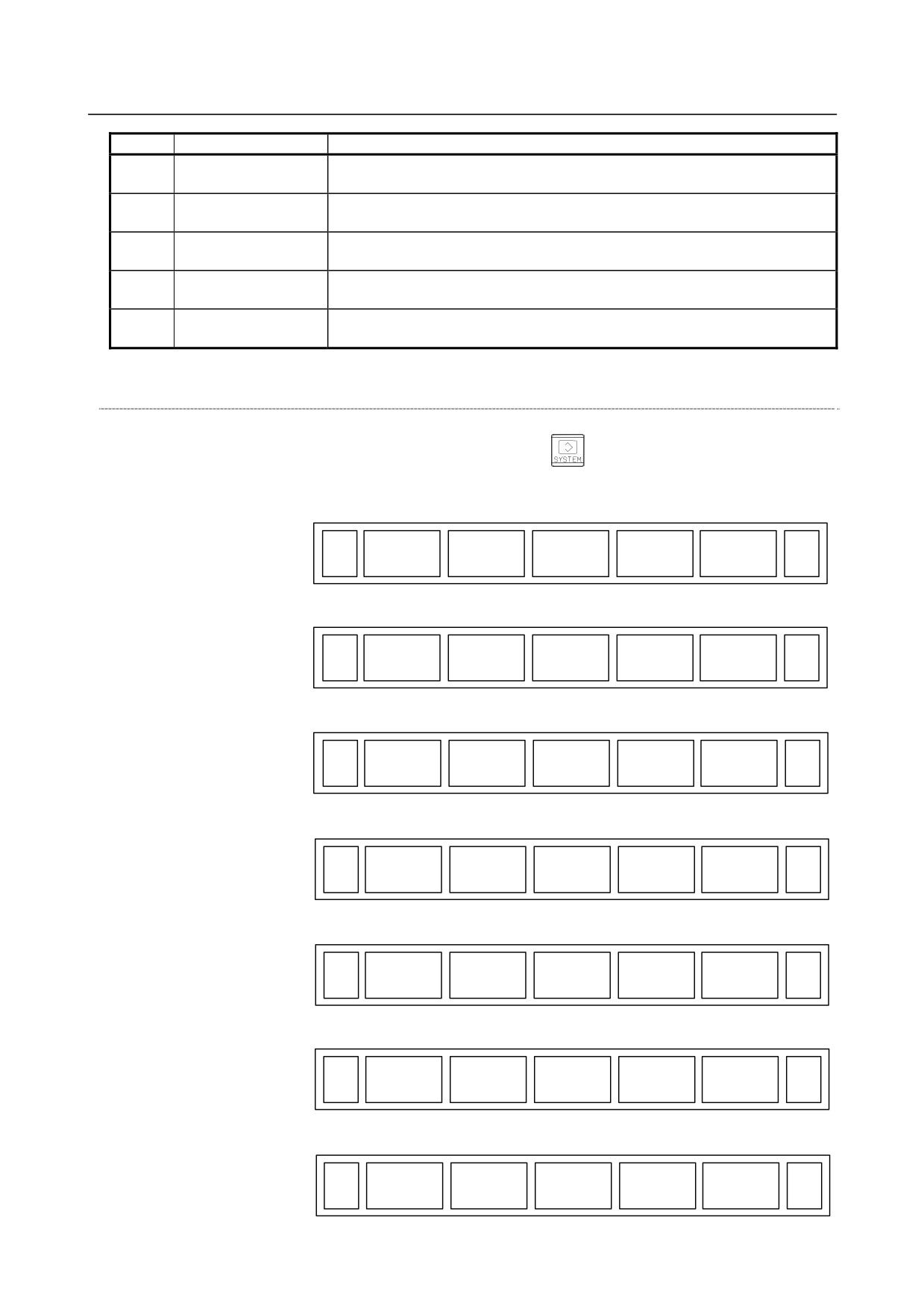
The chapter selection soft keys that belong to the function key
and the function of each screen are
described below.
(1)
(2)
(3)
(4)
(5)
PARAM
DGNOS
SYSTEM
(OPRT)
+
Page 1
(6)
(7)
(8)
(9)
(10)
PITCH
SV.SET
SP.SET
(OPRT)
+
Page 2
(11)
(12)
(13)
(14)
(15)
W.DGNS
ALL IO
OPEHIS
+
Page 3
(16)
(17)
(18)
(19)
(20)
PMCMNT
PMCLAD
PMCCNF
PM.MGR
(OPRT)
+
Page 4
(21)
(22)
(23)
(24)
(25)
COLOR
MAINTE
M-INFO
(OPRT)
+
Page 5
(26)
(27)
(28)
(29)
(30)
FSSB
PRMSET
(OPRT)
+
Page 6
(31)
(32)
(33)
(34)
(35)
EMBED
PCMCIA
ETHBRD
(OPRT)
+
Page 7
- 330 -
B-64304EN/02
OPERATION
2.OPERATIONAL DEVICES
(36)
(37)
(38)
(39)
(40)
RMTDIAG
M-TUN
(OPRT)
+
Page 8
(41)
(42)
(43)
(44)
(45)
ID-INF
MEMORY
(OPRT)
+
Page 9
(46)
(47)
(48)
(49)
(50)
PROF.M
PROF.S
(OPRT)
+
Page 10
Table 2.3.3 (d) System
No.
Chapter menu
Description
(1)
PARAM
Selects the screen for setting parameters.
(PARAMETER)
(2)
DGNOS
Selects the screen for displaying CNC state.
(DIAGNOSIS)
(4)
SYSTEM
Selects the screen for displaying the current system status.
(SYSTEM)
(7)
PITCH
Selects the screen for setting pith error compensation.
(PITCH ERROR)
(8)
SV.SET
Selects the screen for setting the servo-related parameters.
(SERVO SETTING)
(9)
SP.SET
Selects the screen for spindle-related setting.
(SPINDLE SETTING)
(11)
W.DGNS
Selects the screen for displaying data such as servo positional deviation values,
(WAVE DIAG)
torque values, machine signals, and so forth as graphs.
(12)
ALL IO
Selects the screen for inputting or outputting data.
(ALL IO)
(14)
OPEHIS
Selects the screen for displaying the history of operations performed by the
(OPERAT HISTRY)
operator and issued alarms.
(16)
PMCMNT
Selects the screen related to PMC maintenance such as PMC signal state
(PMC MAINTE)
monitoring and tracing, and PMC parameter display/editing.
(17)
PMCLAD
Selects the screen related to ladder display/editing.
(PMC LADDER)
(18)
PMCCNF
Displays the screen for displaying/editing data other than ladders that makes up a
(PMC CONFIG)
sequence program and for setting the PMC function.
(19)
PM.MGR
Select the screen of Power Mate CNC Manager.
(P.MATEMGR.)
(21)
COLOR
Selects the screen for setting colors to be used on the screen.
(COLOR)
(22)
MAINTE
Selects the screen for setting maintenance items to be managed periodically.
(PERIOD MAINTE)
(23)
M-INFO
Selects the screen for displaying information about maintenance performed.
(MAINTE INFO)
(27)
FSSB
Selects the screen for making settings related to the high-speed serial servo bus
(FSSB)
(FSSB: Fanuc Serial Servo Bus).
(28)
PRMSET
Selects the screen for setting parameters necessary for start-up and tuning.
(PARAMETER)
- 331 -
2.OPERATIONAL DEVICES
OPERATION
B-64304EN/02
No.
Chapter menu
Description
(31)
EMBED
Selects the screen for making settings related to the embedded Ethernet
(EMBED PORT)
(embedded port).
(32)
PCMCIA
Selects the screen for making settings related to the embedded Ethernet (PCMCIA
(PCMCIA LAN)
Ethernet card).
(33)
ETHBRD
Selects the screen for making settings related to the fast Ethernet/fast data server.
(ETHER BOARD)
(36)
RMTDIAG
Selects the screen for making settings related to remote diagnosis.
(REMOTE DIAG)
(37)
M-TUN
Displays the screen for setting the parameter set for emphasis on speed (LV1) or
(MCHN TUNING)
emphasis on precision (LV10).
(43)
MEMORY
Selects the screen for displaying the contents of memory.
(MEMORY)
(46)
PROF.M
Selects the screen for making settings related to the Profibus master function.
(PROFI MASTER)
(47)
PROF.S
Selects the screen for making settings related to the Profibus slave function.
(PROFI SLAVE)
* The items enclosed by parentheses on the second line under "Chapter menu" are displayed in the
10.4-inch display unit.
Message screen
The chapter selection soft keys that belong to the function key
and the function of each screen are
described below.
(1)
(2)
(3)
(4)
(5)
ALARM
MSG
HISTRY
+
Page 1
(6)
(7)
(8)
(9)
(10)
MSGHIS
+
Page 2
(11)
(12)
(13)
(14)
(15)
EMB LOG
PCM LOG
BRD LOG
+
Page 3
Table 2.3.3 (e) Message
No.
Chapter menu
Description
(1)
ALARM
Selects the alarm message screen.
(ALARM)
(2)
MSG
Selects the operator message screen.
(MESSAGE)
(3)
HISTRY
Selects the screen for displaying the details of alarms issued so far.
(HISTRY)
(7)
MSGHIS
Selects the external operator message screen.
(MESAGE HISTRY)
(11)
EMB LOG
Selects the screen for displaying error messages related to the embedded
(EMBED LOG)
Ethernet (embedded port).
(12)
PCM LOG
Selects the screen for displaying error messages related to the embedded
(PCMCIA LOG)
Ethernet (PCMCIA Ethernet card).
- 332 -
B-64304EN/02
OPERATION
2.OPERATIONAL DEVICES
No.
Chapter menu
Description
(13)
BRD LOG
Selects the screen for displaying error messages related to the fast
(BOARD LOG)
Ethernet/fast data server.
* The items enclosed by parentheses on the second line under "Chapter menu" are displayed in the
10.4-inch display unit.
Graphic screen
The chapter selection soft keys that belong to the function key
and the function of each screen are
described below.
When the graphic display function is enabled:
(1)
(2)
(3)
(4)
(5)
PARAM
GRAPH
GRAPH
LARGE
(OPRT)
Table 2.3.3 (f) Graphic
No.
Chapter menu
Description
(1)
PARAM
Selects the screen for setting graphic parameters.
(PARAMETER)
(2)
GRAPH
Selects the screen for performing the graphic display of tool paths. (For the M
(GRAPH)
series system)
(3)
GRAPH
Selects the screen for performing the graphic display of tool paths. (For the T series
(GRAPH)
system)
(4)
LARGE
Displays the soft key for setting the scaling factor of graphic display.
(LARGE)
* The items enclosed by parentheses on the second line under "Chapter menu" are displayed in the
10.4-inch display unit.
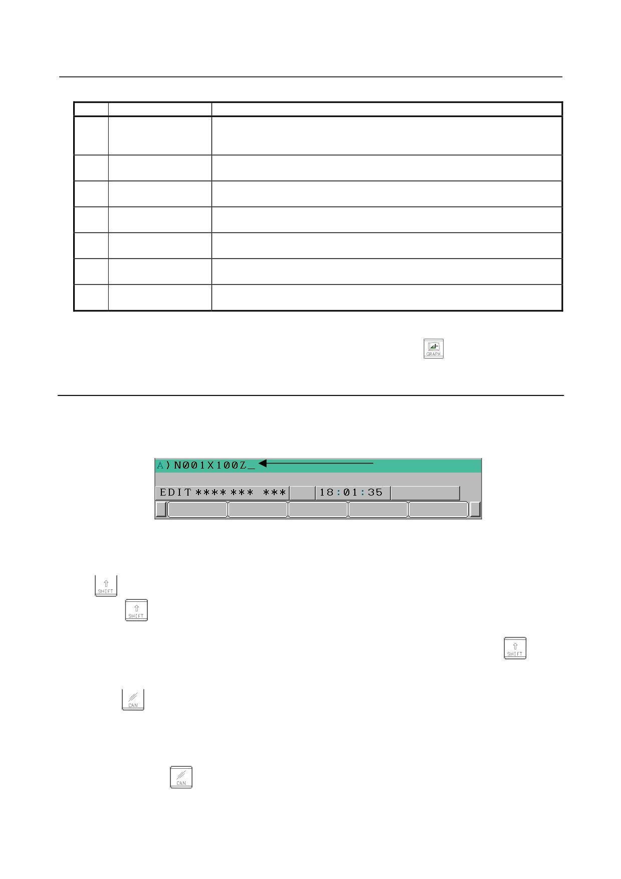
When the dynamic graphic display function is enabled
M series :
(1)
(2)
(3)
(4)
(5)
PARAM
EXEC
EXEC
POS
(OPRT)
+
(6)
(7)
(8)
(9)
(10)
PARAM
3-PLN
(OPRT)
+
T series :
(6)
(7)
(8)
(9)
(10)
PARAM
GRAPH
LARGE
(OPRT)
- 333 -
2.OPERATIONAL DEVICES
OPERATION
B-64304EN/02
Table 2.3.3 (g) Graphic (for dynamic graphic)
No.
Chapter menu
Description
(1)
PARAM
Selects the screen for setting drawing parameters.
(6)
(PARAMETER)
(11)
(2)
EXEC
Selects the screen for drawing tool paths.
(EXEC)
(3)
EXEC
Selects the screen for drawing animation.
(EXEC)
(4)
POS
Selects the screen for displaying tool positions on tool paths during drawing tool
(POSITION)
paths.
(7)
3-PLN
Selects the screen for displaying 3-plane drawings in animated simulation.
(3-PLN)
(13)
GRAPH
Selects the screen for performing the graphic display of tool paths.
(GRAPH)
(14)
LARGE
Displays the soft key for setting the scaling factor of graphic display.
(LARGE)
*1 The items enclosed by parentheses on the second line under "Chapter menu" are displayed in the
10.4-inch display unit.
*2 Item (2) and item (3) are displayed alternately each time function key
is pressed.
2.3.4
Key Input and Input Buffer
When an address and a numeric key are pressed, the character corresponding to that key is input once into
the key input buffer. The contents of the key input buffer is displayed at the bottom of the screen.
In order to indicate that it is key input data, a ">" symbol is displayed immediately in front of it. A "_"
is displayed at the end of the key input data indicating the input position of the next character.
Key input buffer display
Fig. 2.3.4 (a) Key input buffer display
-
Switching between upper and lower key characters
To input the upper character or symbol of the keys that have two characters inscribed on them, first press
the
key and then the key in question.
When the
key is pressed, "_" indicating the input position of the next character changes to "∧" and
the upper character can be input. This status is called the shift status.
When a character is input in shift status the shift status is canceled. Furthermore, if the
key is
pressed in shift status, the shift status is canceled.
It is possible to input up to 128 characters at a time in the key input buffer.
Press the
key to cancel a character or symbol input in the key input buffer.
(Example)
When the key input buffer displays
>N001X100Z_
and the cancel
key is pressed, Z is canceled and
>N001X100_
is displayed.
- 334 -
B-64304EN/02
OPERATION
2.OPERATIONAL DEVICES
2.3.5
Warning Messages
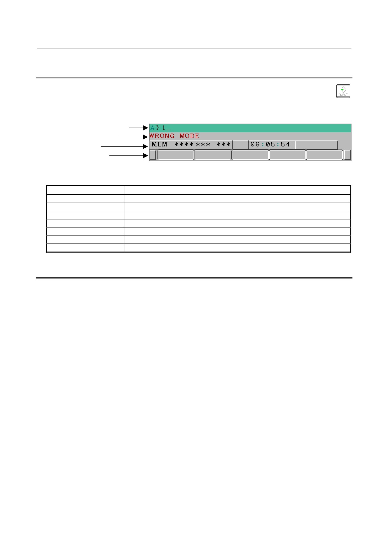
After a character or number has been input from the MDI panel, a data check is executed when
key or a soft key is pressed. In the case of incorrect input data or the wrong operation a flashing
warning message will be displayed on the status display line.
Key input buffer display
Warning message display
State display
Soft key display
Fig. 2.3.5 (a) Warning message display
Table 2.3.5 (a) Warning Messages
Warning message
Content
FORMAT ERROR
The format is incorrect.
WRITE PROTECT
Key input is invalid because of data protect key or the parameter is not write enabled.
DATA IS OUT OF RANGE
The input value exceeds the permitted range.
TOO MANY DIGITS
The input value exceeds the permitted number of digits.
WRONG MODE
Parameter input is not possible in any mode other than MDI mode.
EDIT REJECTED
It is not possible to edit in the current CNC status.
CANNOT USE I/O DEVICE
Because other functions occupy I/O device, I/O device cannot be used.
2.4
EXTERNAL I/O DEVICES
External I/O devices such as a memory card are available.
By using an external I/O device such as a memory card, the following data can be input or output:
1.
Programs
2.
Offset data
3.
Parameters
4.
Custom macro common variables
For how to input or output data and input data from or output it to a memory card, see III-8.
-
Parameter setting
Before an external input/output device can be used, parameters must be set as follows.
- 335 -