FANUC Series 0i-MODEL D, Series 0i Mate-MODEL D. OPERATOR'S MANUAL - page 13
2.OPERATIONAL DEVICES
OPERATION
B-64304EN/02
CNC
Main board
Channel 1
Channel 2
JA56A
JA36A
RS-232-C
RS-232-C
Reader/
Reader/
puncher
puncher
I/O CHANNEL=0
I/O CHANNEL=2
or
I/O CHANNEL=1
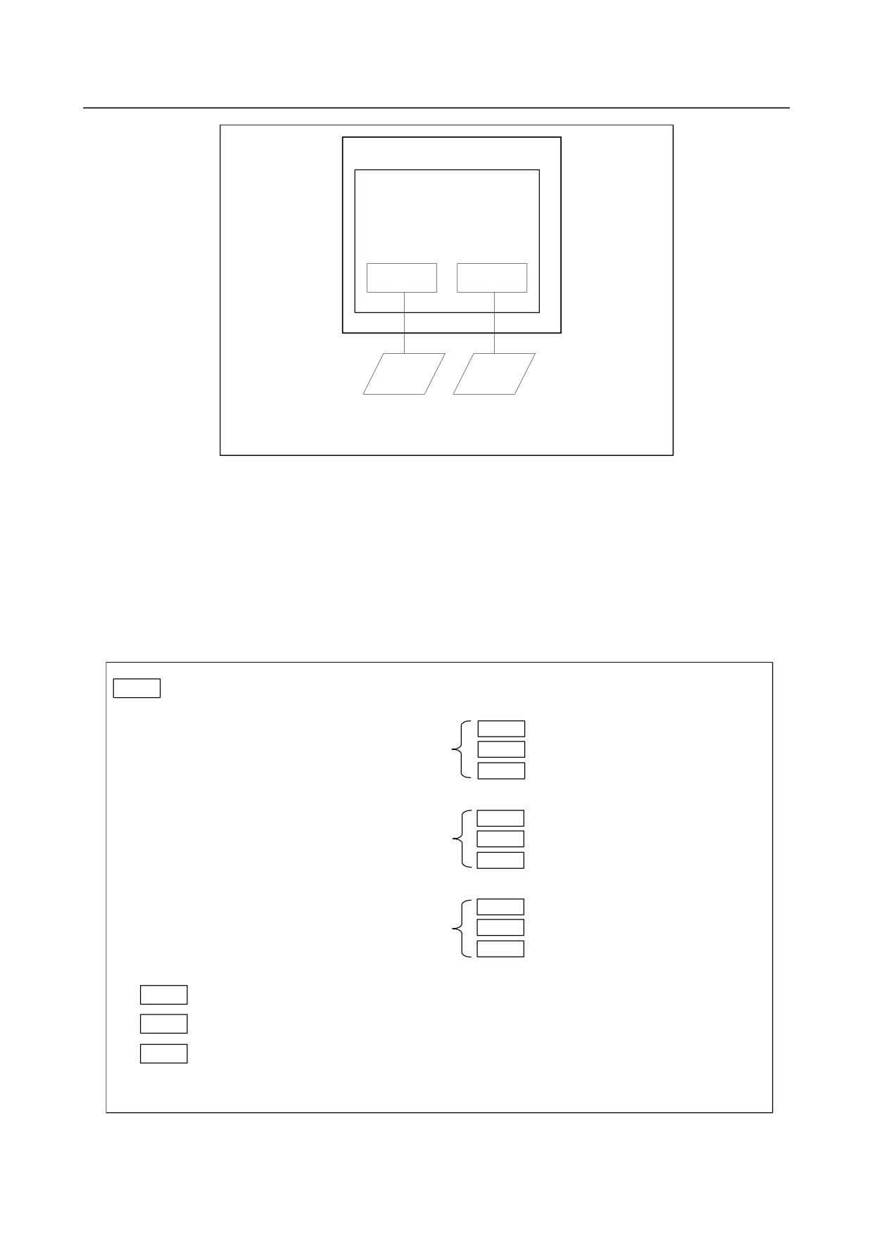
This CNC has a total of two channels of reader/puncher interfaces. It also has a memory card interface.
The input/output device to be used is specified by setting the channel (interface) connected to that device
in setting parameter I/O CHANNEL.
The specified data, such as a baud rate and the number of stop bits, of an input/output device connected to
a specific channel must be set in parameters for that channel in advance. (These settings are not required
for the memory card interface.)
For channel 1, two combinations of parameters to specify the input/output device data are provided.
The following shows the interrelation between the reader/puncher interface parameters for the channels.
I/O CHANNEL
Input/output channel number (parameter No.0020)
0020
or foreground input
↓
Set channels to be used
0101
Stop bit and other data
for data input/output.
I/O CHANNEL=0
0102
Number specified for the input/output device
(Channel 1)
I/O CHANNEL (0 to 9)
0103
Baud rate
=0 : Channel 1
=1 : Channel 1
=2 : Channel 2
0111
Stop bit and other data
=3 : Channel 3
I/O CHANNEL=1
0112
Number specified for the input/output device
:
(Channel 1)
:
0113
Baud rate
:
Input/output to and from the
memory card interface, etc. is also
0121
Stop bit and other data
possible.
I/O CHANNEL=2
0122
Number specified for the input/output device
(Channel 2)
When bit
0
(IO4) of parameter
0123
Baud rate
No.0110 is set
:
0021
Foreground output
:
:
0022
Background input
I/O CHANNEL=9
0023
Background input
The channel setting is the same as
No.0020.
- 336 -
B-64304EN/02
OPERATION
2.OPERATIONAL DEVICES
2.5
POWER ON/OFF
2.5.1
Turning on the Power
Procedure of turning on the power
Procedure
1
Check that the CNC or machine is visually normal. (For example, check that front door and rear
door are closed.)
2
Turn on the power according to the manual issued by the machine tool builder.
3
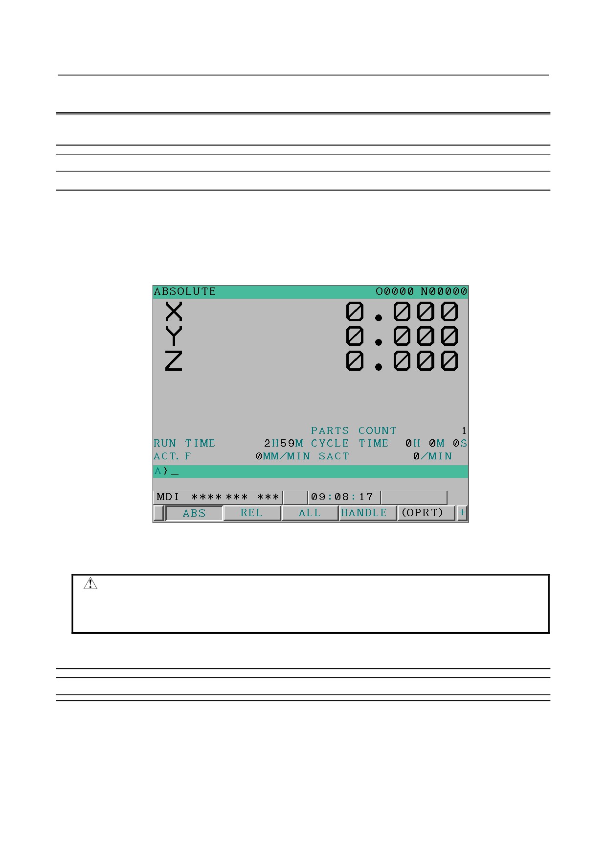
After the power is turned on, check that the position screen is displayed. An alarm screen is
displayed if an alarm occurs upon power-on.
Fig. 2.5.1 (a) Position screen (example for the 8.4-inch display unit)
4
Check that the fan motor is rotating.
WARNING
Until the positional or alarm screen is displayed at the power on, do not touch
them. Some keys are used for the maintenance or special operation purpose.
When they are pressed, unexpected operation may be caused.
2.5.2
Power Disconnection
Procedure of power disconnection
Procedure
1
Check that the LED indicating the cycle start is off on the operator's panel.
2
Check that all movable parts of the CNC machine tool is stopping.
3
If an external input/output device such as the Handy File is connected to the CNC, turn off the
external input/output device.
4
Continue to press the <POWER OFF> button for about 5 seconds.
5
Refer to the machine tool builder's manual for turning off the power to the machine.
- 337 -
3.MANUAL OPERATION
OPERATION
B-64304EN/02
3 MANUAL OPERATION
MANUAL OPERATION are eight kinds as follows :
3.1 MANUAL REFERENCE POSITION RETURN
338
3.2 JOG FEED (JOG)
339
3.3 INCREMENTAL FEED
341
3.4 MANUAL HANDLE FEED
342
3.5 MANUAL ABSOLUTE ON AND OFF
345
3.6 DISTANCE CODED LINEAR SCALE INTERFACE
349
3.7 LINEAR SCALE WITH DISTANCE-CODED REFERENCE MARKS (SERIAL)
354
3.8 MANUAL HANDLE RETRACE
357
3.1
MANUAL REFERENCE POSITION RETURN
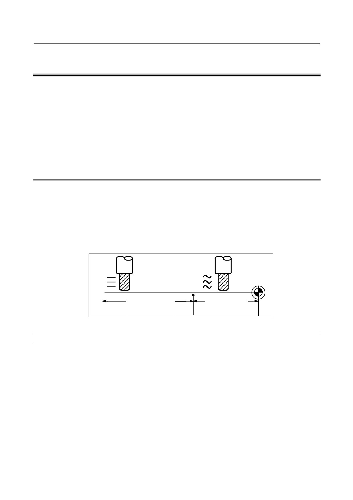
The tool is returned to the reference position as follows :
The tool is moved in the direction specified in bit 5 (ZMI) of parameter No.1006 for each axis with the
reference position return switch on the machine operator's panel. The tool moves to the deceleration point
at the rapid traverse rate, then moves to the reference position at the FL speed. The rapid traverse rate and
FL speed are specified in parameters Nos. 1424,1421, and 1425.
Four step rapid traverse override is effective during rapid traverse.
When the tool has returned to the reference position, the reference position return completion LED goes
on. The tool generally moves along only a single axis, but can move along three axes simultaneously
when specified so in bit 0 (JAX) of parameter No.1002.
Reference position
Deceleration point
Rapid traverse motion
Decelerated motion
Rapid traverse rate
FL speed
(rapid traverse
override is effective)
Fig. 3.1 (a) Manual reference position return
Procedure for manual reference position return
Procedure
1
Press the reference position return switch, one of the mode selection switches.
2
To decrease the feedrate, press a rapid traverse override switch.
3
Press the feed axis and direction selection switch corresponding to the axis and direction for
reference position return. Continue pressing the switch until the tool returns to the reference position.
The tool can be moved along three axes simultaneously when specified so in an appropriate
parameter setting. The tool moves to the deceleration point at the rapid traverse rate, then moves to
the reference position at the FL speed set in a parameter. When the tool has returned to the reference
position, the reference position return completion LED goes on.
4
Perform the same operations for other axes, if necessary.
The above is an example. Refer to the appropriate manual provided by the machine tool builder for the
actual operations.
- 338 -

B-64304EN/02
OPERATION
3.MANUAL OPERATION
ZERO POSITION
MIRRROR IMAGE
X Y Z C X2
Y2
Z2
X Y Z
PROGRAM M02/ MANU SPINDLE
ATC
STOP M30
ABS ORI
TAP READY
NC? MC?
Fig. 3.1 (b)
Explanation
-
Automatically setting the coordinate system
Bit 0 (ZPR) of parameter No.1201 is used for automatically setting the coordinate system. When ZPR is
set, the coordinate system is automatically determined when manual reference position return is
performed.
When α, β and γ are set in parameter 1250, the workpiece coordinate system is determined so that
reference point on the tool holder or the position of the tip of the reference tool is X= α, Y = β, Z = γ
when reference position return is performed. This has the same effect as specifying the following
command for reference position return:
G92XαYβZγ;
When the workpiece coordinate system is used (bit 0 (NWZ) of parameter No. 8136 is 0), this function
cannot be used.
Limitation
-
Moving the tool again
Once the reference position return completion LED lights at the completion of reference position return,
the tool does not move unless the reference position return switch is turned off.
-
Reference position return completion LED
The reference position return completion LED is extinguished by either of the following operations:
• Moving from the reference position.
• Entering an emergency stop state.
-
The distance to return to reference position
For the distance (Not in the deceleration condition) to return the tool to the reference position, refer to the
manual issued by the machine tool builder.
3.2
JOG FEED (JOG)
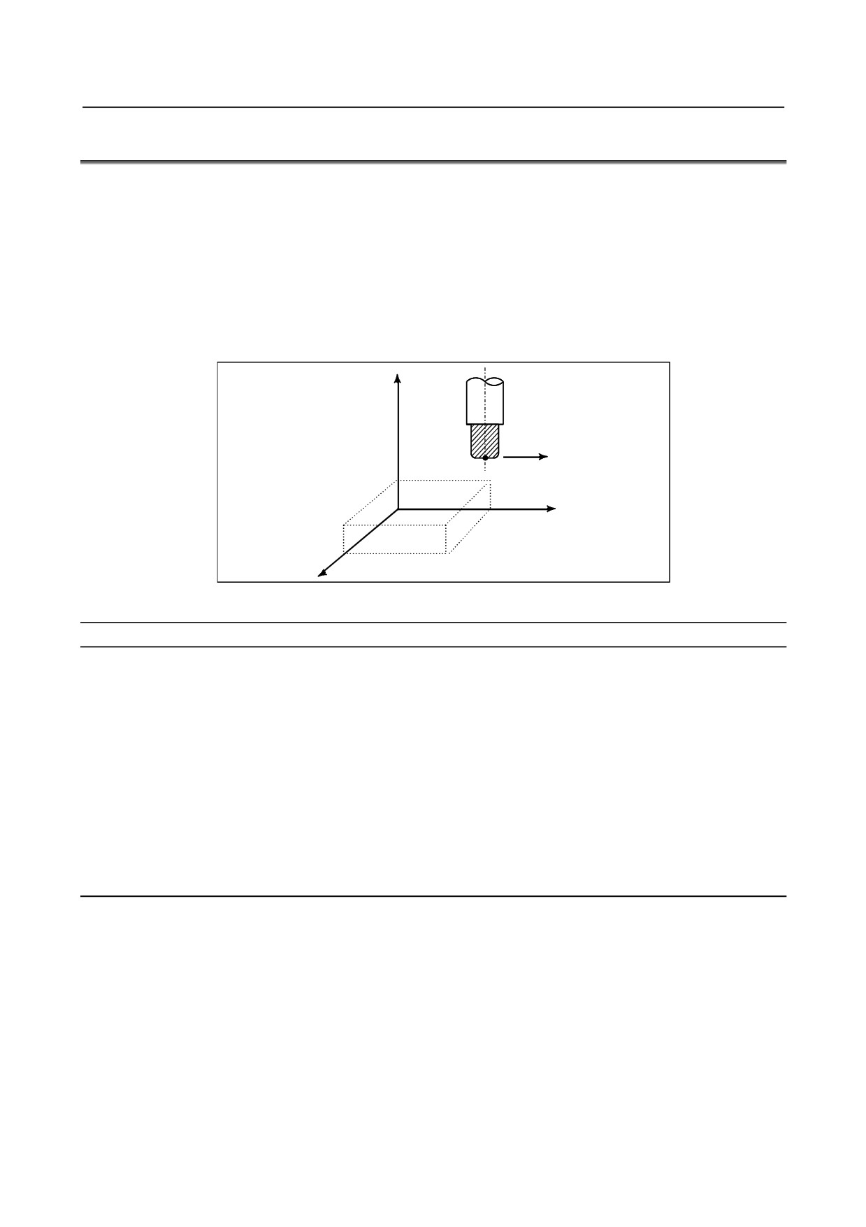
In the jog mode, pressing a feed axis and direction selection switch on the machine operator's panel
continuously moves the tool along the selected axis in the selected direction.
The jog feedrate is specified in a parameter No.1423.
The jog feedrate can be adjusted with the jog feedrate override dial.
Pressing the rapid traverse switch moves the tool at the rapid traverse feedrate No. 1424 regardless of the
position of the jog feedrate override dial. This function is called the manual rapid traverse.
Manual operation is allowed for one axis at a time. 3 axes can be selected at a time by bit 0 (JAX) of
parameter No.1002.
- 339 -

3.MANUAL OPERATION
OPERATION
B-64304EN/02
Z
Y
While a switch is pressed, the tool moves
in the direction specified by the switch.
X
Fig. 3.2 (a) Jog Feed (JOG)
Procedure for JOG feed
Procedure
1
Press the jog switch, one of the mode selection switches.
2
Press the feed axis and direction selection switch corresponding to the axis and the direction where
the tool is to be moved. While the switch is pressed, the tool moves at the feedrate specified in the
parameter No. 1423. The tool stops when the switch is released.
3
The jog feedrate can be adjusted with the jog feedrate override dial.
4
Pressing the rapid traverse switch while pressing a feed axis and direction selection switch moves
the tool at the rapid traverse rate while the rapid traverse switch is pressed. Rapid traverse override
by the rapid traverse override switches is effective during rapid traverse.
The above is an example. Refer to the appropriate manual provided by the machine tool builder for the
actual operations.
Explanation
-
Manual per revolution feed
The manual per revolution feed is enabled for jog feed by setting bit 4 (JRV) of parameter No.1402.
In manual per revolution feed, jog feed is performed at the feedrate of the feed amount per spindle
revolution set by parameter No. 1423 multiplied by the jog feedrate override multiplied by the spindle
speed.
During manual per revolution feed, the tool is jogged at the following feedrate:
Feed distance per rotation of the spindle (mm/rev) (specified with parameter No. 1423) × JOG feedrate
override × actual spindle speed (rev/min).
Limitation
-
Acceleration/deceleration for rapid traverse
Feedrate, time constant and method of automatic acceleration/ deceleration for manual rapid traverse are
the same as G00 in programmed command.
-
Change of modes
Changing the mode to the jog mode while pressing a feed axis and direction selection switch does not
enable jog feed. To enable jog feed, enter the jog mode at first, then press a feed axis and direction
selection switch.
-
Rapid traverse prior to reference position return
If reference position return is not performed after power-on, pushing rapid traverse button does not
actuate the rapid traverse but the remains at the JOG feedrate. This function can be disabled by setting bit
0 (RPD) of parameter No.1401.
- 340 -
B-64304EN/02
OPERATION
3.MANUAL OPERATION
3.3
INCREMENTAL FEED
In the incremental (INC) mode, pressing a feed axis and direction selection switch on the machine
operator's panel moves the tool one step along the selected axis in the selected direction. The minimum
distance the tool is moved is the least input increment. Each step can be 10, 100, or 1000 times the least
input increment.
With using bit 2 (HNT) of parameter No. 7103, each step can be additionally 10 times the lest input
increment.
The feedrate set in parameter No. 1423 is applied.
By using the manual feedrate override signal, the feedrate can be increased or decreased.
The tool can also be moved at the rapid traverse rate by using the manual rapid traverse selection signal,
independent of the manual feedrate override signal.
Z
Each time a switch is
Tool
pressed, the tool moves one
step in the direction
specified by the switch.
Y
X
Fig. 3.3 (a) Incremental feed
Procedure for incremental feed
Procedure
1
Press the INC switch, one of the mode selection switches.
2
Select the distance to be moved for each step with the magnification dial.
3
Press the feed axis and direction selection switch corresponding to the axis and direction the tool is
to be moved. Each time a switch is pressed, the tool moves one step. The feedrate is the same as
the jog feedrate.
4
Pressing the rapid traverse switch while pressing a feed axis and direction selection switch moves
the tool at the rapid traverse rate. Rapid traverse override by the rapid traverse override switch is
effective during rapid traverse.
The above is an example. Refer to the appropriate manual provided by the machine tool builder for the
actual operations.
Explanation
-
Travel distance specified with a diameter
For specification with a diameter, the travel distance is a diameter value.
- 341 -
3.MANUAL OPERATION
OPERATION
B-64304EN/02
3.4
MANUAL HANDLE FEED
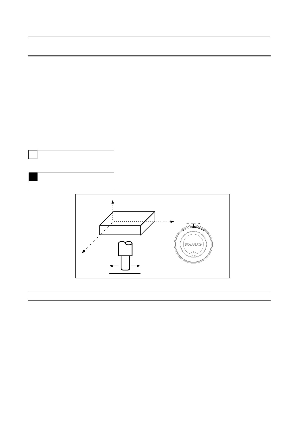
In the handle mode, the tool can be minutely moved by rotating the manual pulse generator on the
machine operator's panel. Select the axis along which the tool is to be moved with the handle feed axis
selection switches.
The minimum distance the tool is moved when the manual pulse generator is rotated by one graduation is
equal to the least input increment. It can be multiplied by one of four scaling factors: 1, 10, and two
arbitrary values set in parameters Nos. 7113 and 7114. It is possible to set arbitrary scaling factors for
each axis (set in parameters Nos. 12350 and 12351) as well as arbitrary scaling factors common to all
axes (set in parameters Nos. 7113 and 7114). If parameter No. 12350 is not set, the setting of parameter
No. 7113 is used. If parameter No. 12351 is not set, the setting of parameter No. 7114 is used. With
bit 2 (HNT) of parameter No. 7103, the minimum distance can be further 10 times greater.
The above parameters are valid for manual handle interruption.
The number of manual pulse generators is given below.
T
• Up to two (Two axes can be moved at the same time.)
Up to three with an optional function for 0i-TD.
M
• Up to three (Three axes can be moved at the same time.)
Z
Y
X
Manual pulse generator
Fig. 3.4 (a) Manual handle feed
Procedure for manual handle feed
Procedure
1
Press the handle switch, one of the mode selection switches.
2
Select the axis along which the tool is to be moved by pressing a handle feed axis selection switch.
3
Select the magnification for the distance the tool is to be moved by pressing a handle feed
magnification switch. The minimum distance the tool is moved when the manual pulse generator is
rotated by one graduation is equal to the least input increment.
4
Move the tool along the selected axis by rotating the handle. Rotating the handle 360 degrees moves
the tool the distance equivalent to 100 graduations.
The above is an example. Refer to the appropriate manual provided by the machine tool builder for the
actual operations.
- 342 -
B-64304EN/02
OPERATION
3.MANUAL OPERATION
Explanation
-
Availability of manual pulse generator in Jog mode (JHD)
When bit 0 (JHD) of parameter No. 7100 is set to 1, both jog feed and manual handle feed can be used in
JOG mode.
When bit 0 (JHD) of parameter No. 7100 is set to 1, both manual handle feed and incremental feed can be
used in HANDLE mode.
-
Manual handle feed in TEACH IN JOG mode (THD)
By setting bit 1 (THD) of parameter No. 7100, manual handle feed in TEACH IN JOG mode can be
enabled or disabled.
-
When manual handle feed exceeding the rapid traverse rate is specified
The amount of pulses exceeding the rapid traverse rate can be saved by CNC as B. And amount of
pulses B will be output as pulses C.
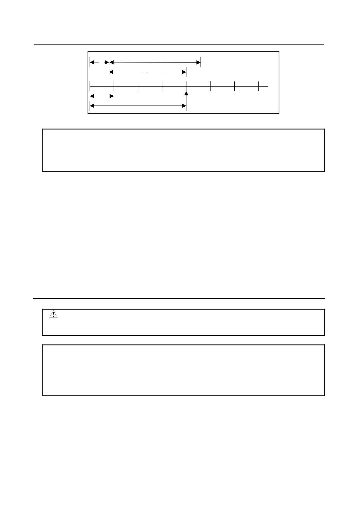
A: Amount of pulses corresponds to value of
Rapid Traverse Rate.
B: Amount of pulses accumulated in CNC.
C: Amount of pulses the same as B.
B
Rapid
traverse
rate
A
C
t
Fig. 3.4 (b) Amount of pulses output by CNC in Manual Handle Feed
Amount of pulses B is calculated in 2 cases as following:
In case of
1)
Parameter No.7117 = 0
The feedrate is clamped at the Rapid Traverse Rate and generated pulses exceeding the Rapid
Traverse Rate are ignored (B=0).
In case of
2)
Parameter No.7117 > 0
The feedrate is clamped as the Rapid Traverse Rate, but the pulses exceeding the Rapid Traverse
Rate is not ignored. Amount of pulses accumulated in CNC is calculated as following. (Although the
rotation of manual pulse generator is stopped, if there is pulses accumulated in CNC, it will be
output and the tool will move as long as amount of it.)
Magnification set by MP1,MP2<Gn019.4,5> is m, value of parameter No.7117 is n.
n < m: Clamping is set performed at value of parameter No.7117.
n ≥ m: Amount A+B, shown in figure, which’s value is multiple of m and small than n. As a result,
clamping is performed as an integral multiple of the selected magnification.
- 343 -
3.MANUAL OPERATION
OPERATION
B-64304EN/02
A: Amount of pulses the same as
n
Rapid Traverse Rate.
A
B: Amount of pulses saved in CNC.
k : Integer number
B
m
A+B=k⋅m
Pulses over (k⋅m) will be ignored
Fig. 3.4 (c) Amount of pulses exceeding the Rapid Traverse Rate (n ≥ m)
NOTE
Due to change of mode, clamping can be performed not as an integral multiple
of the selected magnification.
The distance the tool moves may not match the graduations on the manual
pulse generator.
-
Upper feedrate limit in manual handle feed
The upper feedrate limit depends on the input signal (maximum manual handle feedrate switch signal
HNDLF) from the PMC as follows:
• When HNDLF is set to 0, the feedrate is clamped to the manual rapid traverse rate (parameter No.
1424).
• When HNDLF is set to 1, the feedrate is clamped to the feedrate set in parameter No. 1434.
-
Movement direction of an axis to the rotation of MPG (HNGx)
Bit 0 (HNGx) of parameter No 7102 switches the direction of MPG in which the tool moves along an axis,
corresponding to the direction in which the handle of the manual pulse generator is rotated.
This parameter is valid only for the following functions:
• Manual handle feed
• Manual handle interruption
Limitation
WARNING
Rotating the handle quickly with a large magnification such as ×100 moves the
tool too fast. The feedrate is clamped at the rapid traverse feedrate.
NOTE
Rotate the manual pulse generator at a rate of five rotations per second or lower.
If the manual pulse generator is rotated at a rate higher than five rotations per
second, the tool may not stop immediately after the handle is no longer rotated
or the distance the tool moves may not match the graduations on the manual
pulse generator.
- 344 -
B-64304EN/02
OPERATION
3.MANUAL OPERATION
3.5
MANUAL ABSOLUTE ON AND OFF
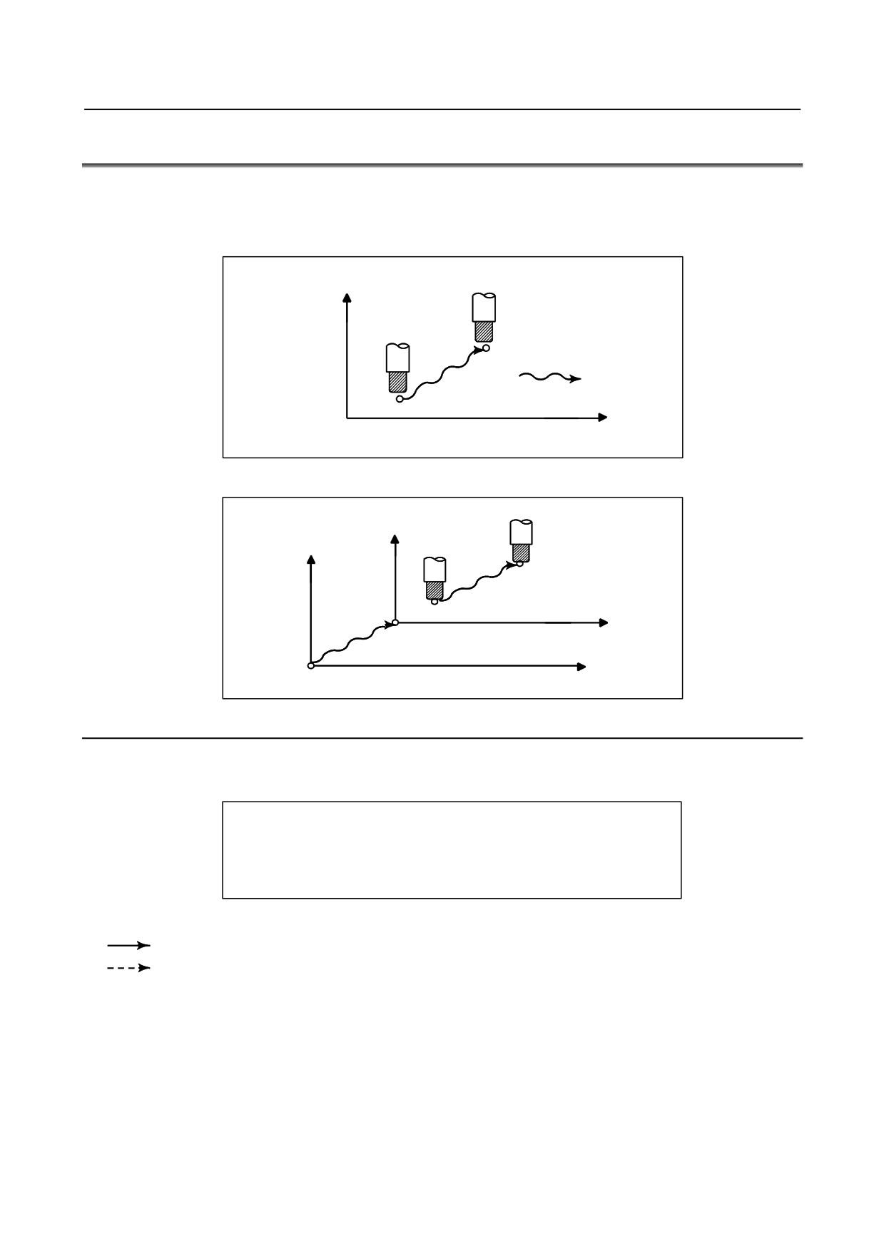
Whether the distance the tool is moved by manual operation is added to the coordinates can be selected
by turning the manual absolute switch on or off on the machine operator's panel. When the switch is
turned on, the distance the tool is moved by manual operation is added to the coordinates. When the
switch is turned off, the distance the tool is moved by manual operation is not added to the coordinates.
Y axis
P2
Manual operation
P1
O
X axis
The coordinates values change by the
amount of manual operation.
Fig. 3.5 (a) Coordinates with the switch ON
Y2
Y1
P2
O2
P1
X2
X1
O1
The coordinates do not change.
Fig. 3.5 (b) Coordinates with the switch OFF
Explanation
The following describes the relation between manual operation and coordinates when the manual absolute
switch is turned on or off, using a program example.
G01G90 X100.0Y100.0F10 ;
<1>
X200.0Y150.0
;
<2>
X300.0Y200.0
;
<3>
Fig. 3.5 (c) Program example
The subsequent figures use the following notation:
Movement of the tool when the switch is on
Movement of the tool when the switch is off
The coordinates after manual operation include the distance the tool is moved by the manual operation.
When the switch is off, therefore, subtract the distance the tool is moved by the manual operation.
- 345 -
3.MANUAL OPERATION
OPERATION
B-64304EN/02
-
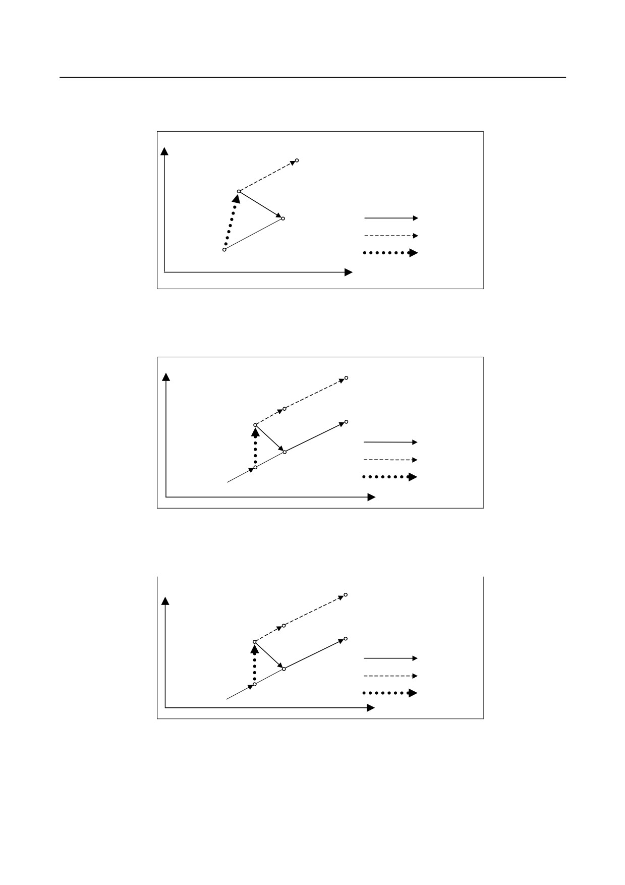
Manual operation after the end of block
Coordinates when block <1> has been executed after manual operation (X-axis +20.0, Y-axis +100.0) at
the end of movement of block <2>.
Y
(220.0 , 250.0)
(120.0 , 200.0)
Switch ON
(200.0 , 150.0)
Switch OFF
Manual
(100.0 , 100.0)
operation
X
Fig. 3.5 (d) Manual operation after the end of block
-
Manual operation after a feed hold
Coordinates when the feed hold button is pressed while block <2> is being executed, manual operation
(Y-axis + 75.0) is performed, and the cycle start button is pressed and released.
Y
(300.0 , 275.0)
(200.0 , 225.0)
(150.0 , 200.0)
(300.0 , 200.0)
Switch ON
(200.0 , 150.0)
Switch OFF
(150.0 , 125.0)
Feed hold stop point
Manual
operation
X
Fig. 3.5 (e) Manual operation after a feed hold
-
When reset after a manual operation following a feed hold
Coordinates when the feed hold button is pressed while block <2> is being executed, manual operation
(Y-axis +75.0) is performed, the control unit is reset with the RESET button, and block <2> is read again.
Y
(300.0 , 275.0)
(200.0 , 225.0)
(150.0 , 200.0)
(300.0 , 200.0)
Switch ON
(200.0 , 150.0)
Switch OFF
(150.0 , 125.0)
Feed hold stop point
Manual
operation
X
Fig. 3.5 (f) When reset after a manual operation following a feed hold
- 346 -
B-64304EN/02
OPERATION
3.MANUAL OPERATION
-
When a movement command in the next block is only one axis
When there is only one axis in the following command, only the commanded axis returns.
Program
N1 G90 G01 X100. Y100. F500 ;
N2 X200.0 ;
Y
N3 Y150.0 ;
(200.0 , 150.0)
N3
N2
(200.0 , 100.0)
Switch ON
(100.0 , 100.0)
Switch OFF
N1
Manual
operation
X
Fig. 3.5 (g) When a movement command in the next block is only one axis
-
When the next move block is an incremental
When the following commands are incremental commands, operation is the same as when the switch is
OFF.
-
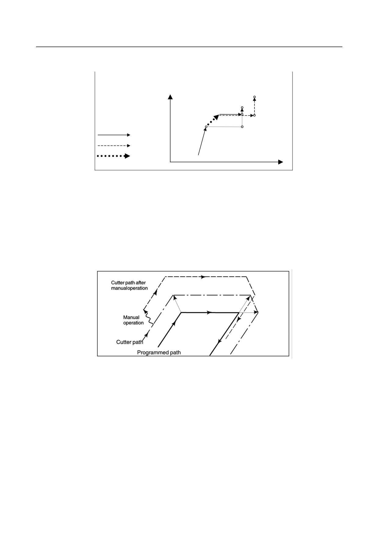
Manual operation during cutter or tool nose radius compensation
• When the switch is OFF
After manual operation is performed with the switch OFF during cutter or tool nose radius
compensation, automatic operation is restarted then the tool moves parallel to the movement that
would have been performed if manual movement had not been performed.
The amount of separation equals to the amount that was performed manually.
• When the switch is ON during cutter or tool nose radius compensation
Operation of the machine upon return to automatic operation after manual intervention with the
switch is ON during execution with an absolute command program in the cutter or tool nose radius
compensation mode will be described. The vector created from the remaining part of the current
block and the beginning of the next block is shifted in parallel. A new vector is created based on the
next block, the block following the next block and the amount of manual movement. This also
applies when manual operation is performed during cornering.
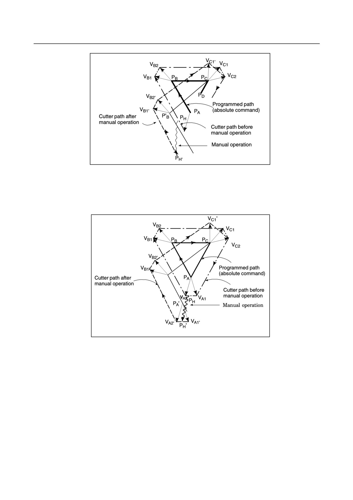
• Manual operation performed in other than cornering
Assume that the feed hold was applied at point PH while moving from PA to PB of programmed path
PA, PB, and PC and that the tool was manually moved to PH'. The block end point PB moves to the
point PB' by the amount of manual movement, and vectors VB1 and VB2 at PB also move to VB1' and
VB2'. Vectors VC1 and VC2 between the next two blocks PB - PC and PC - PD are discarded and new
vectors VC1' and VC2' (VC2' = VC2 in this example) are produced from the relation between PB' - PC
and PC - PD. However, since VB2' is not a newly calculated vector, correct offset is not performed at
block PB' - PC. Offset is correctly performed after PC.
- 347 -
3.MANUAL OPERATION
OPERATION
B-64304EN/02
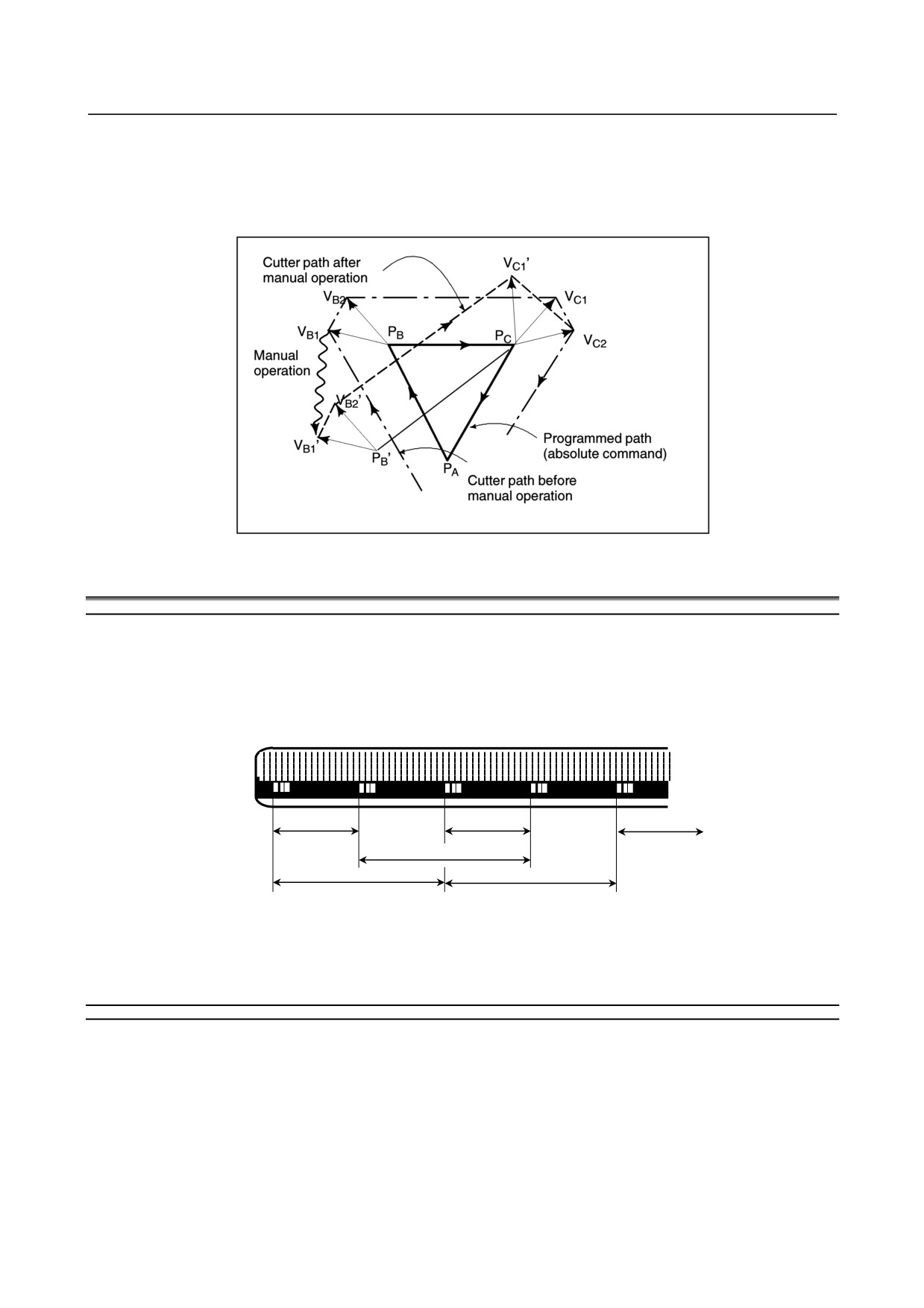
• Manual operation during cornering
This is an example when manual operation is performed during cornering. VA2', VB1', and VB2' are
vectors moved in parallel with VA2, VB1 and VB2 by the amount of manual movement. The new
vectors are calculated from VC1 and VC2. Then correct cutter or tool nose radius compensation is
performed for the blocks following PC.
- 348 -
B-64304EN/02
OPERATION
3.MANUAL OPERATION
• Manual operation after single block stop
Manual operation was performed when execution of a block was terminated by single block stop.
Vectors VB1 and VB2 are shifted by the amount of manual operation. Sub-sequent processing is the
same as case a described above. An MDI operation can also be intervened as well as manual
operation. The movement is the same as that by manual operation.
3.6
DISTANCE CODED LINEAR SCALE INTERFACE
Overview
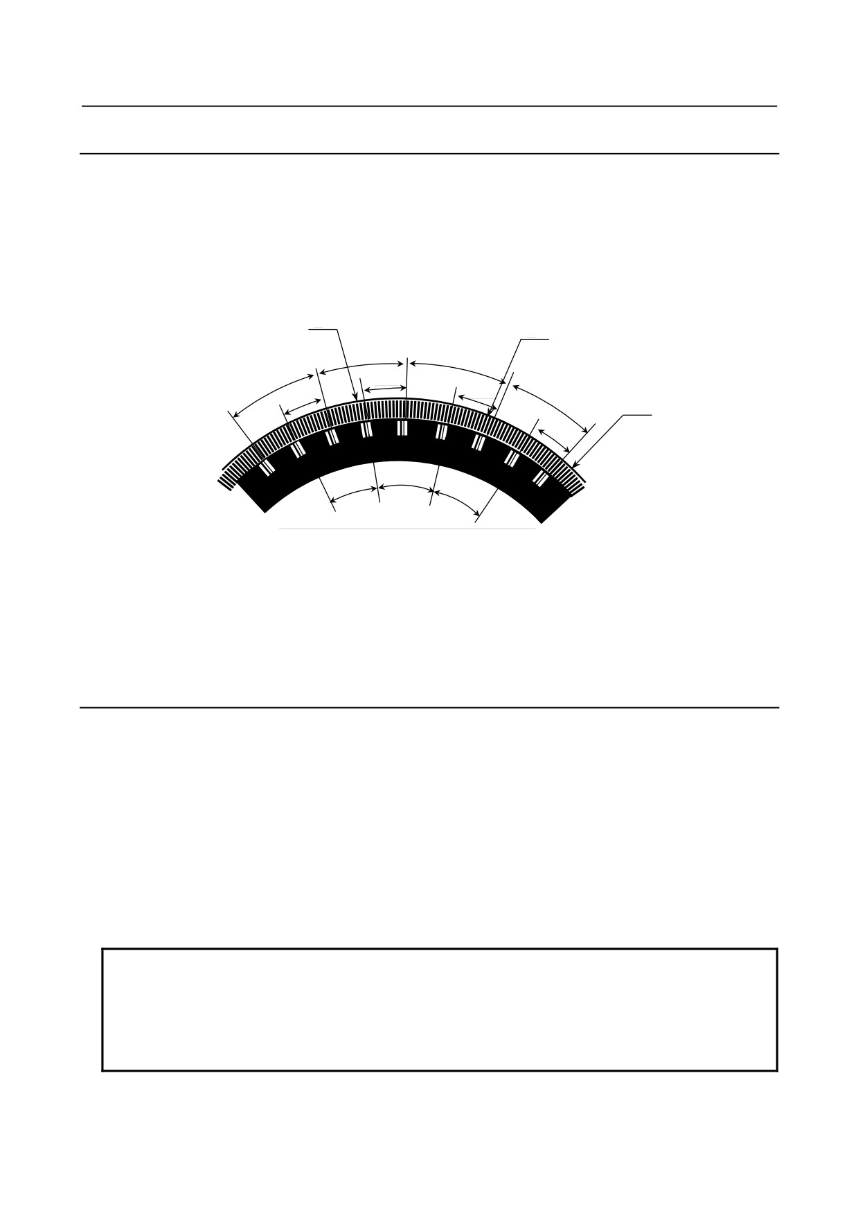
The interval of each reference marks of distance coded linear scale are variable. Accordingly, if the
interval is determined, the absolute position can be determined. The CNC measures the interval of
reference marks by axis moving of short distance and determines the absolute position. Consequently the
reference position can be established without moving to reference position.
eference mark 1 Reference mark 2
Reference mark 1
Reference mark 2
R
Reference mark 1
10.02
10.04
10.06
20.02
20.00
20.00
Fig. 3.6 (a) Example of distance coded linear scale
This is an optional function.
3.6.1
Procedure for Reference Position Establishment
Procedure
(1) Select the JOG mode, and set the manual reference position return selection signal ZRN to "1".
(2) Set a direction selection signal(+J1,-J1,+J2,-J2,…) for a target axis.
(3) The axis is fed at a constant low speed (reference position return FL feedrate specified by parameter
(No.1425) setting).
(4) When a reference mark is detected, the axis stops, then the axis is fed at a constant low speed again.
(5) Above (4) is executed repeatedly until two, three or four reference marks are detected. And
absolute position is determined and reference position establishment signal (ZRF1,ZRF2,ZRF3, …)
turns to "1".
(A number of reference marks is determined by bit 2 (DC2x) and 1 (DC4x) of parameter No.1802.)
- 349 -
3.MANUAL OPERATION
OPERATION
B-64304EN/02
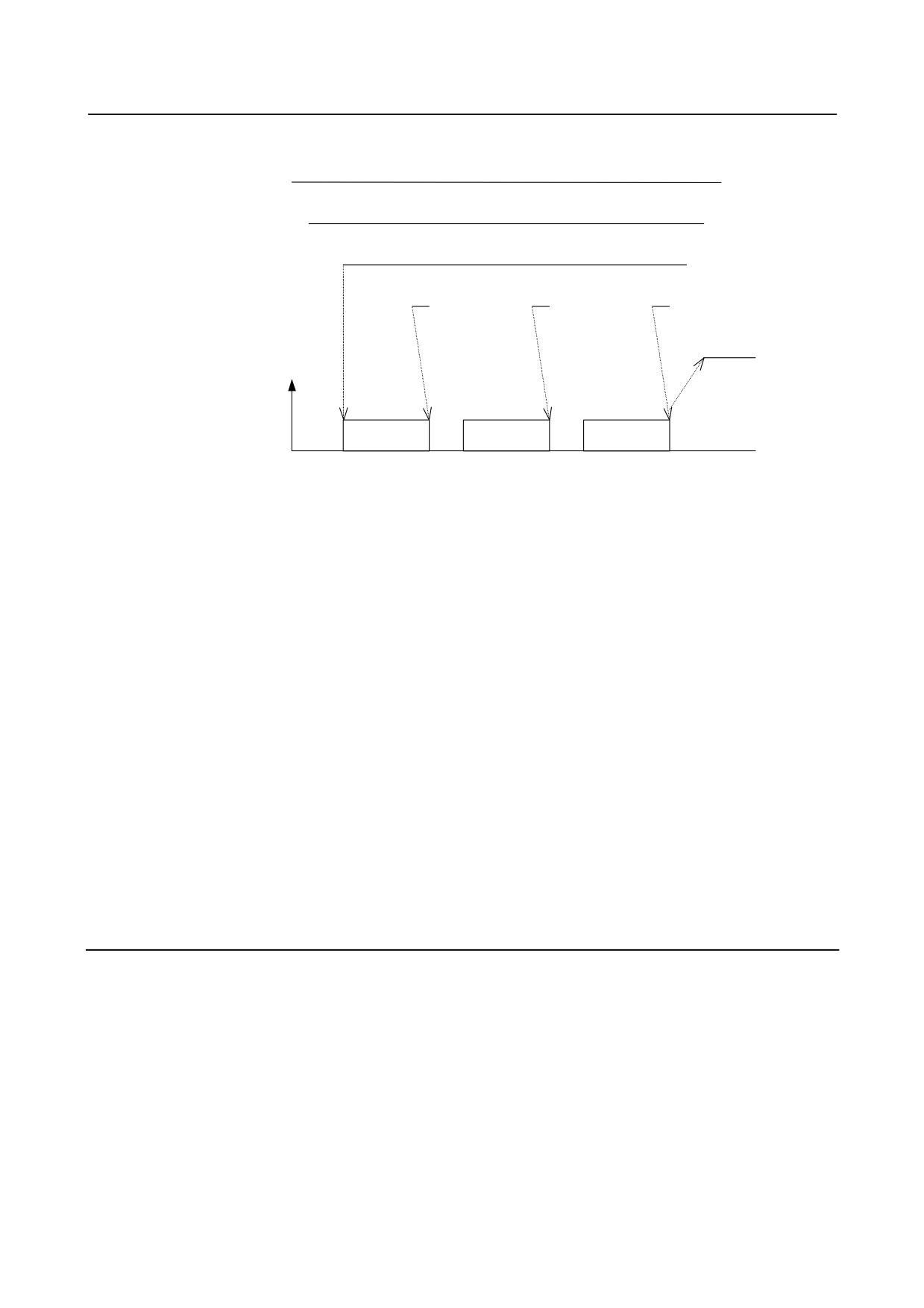
The timing chart for this procedures is given below.
JOG
ZRN
+J1
Reference mark
ZRF1
Feedrate
FL rate
FL rate
FL rate
Fig. 3.6.1 (a) Timing chart for reference position establishment
-
Procedure for establishing a reference position through automatic operation
If an automatic reference position return (G28) is specified before a reference position is not established,
steps (3) to (5) above are performed automatically.
After the reference position is established, the automatic reference position return is performed.
-
Stopping the operation for establishing a reference position
The operation for establishing a reference position is stopped if any of the following operations is
performed in steps (3) to (5), described above.
• Reset
• Setting the feed axis direction selection signal (+J1, -J1, +J2, -J2, etc.) to 0
If any of the following operations is performed during the operation of automatic reference position
return (G28) before a reference position is not established, the operation for establishing a reference
position stops:
• Reset
• Performing feed hold during movement from an intermediate position
If the operation for establishing a reference position is stopped by an operation other than a reset, the
operation for establishing a reference position must be reset and resumed.
3.6.2
Reference Position Return
(1) When the reference position is not established and the axis moved by turning the feed axis direction
signal (+J1,-J1,+J2,-J2,...) to "1" in REF mode, the reference position establishment procedure is
executed.
(2) When the reference position is already established and the axis is moved by turning the feed axis
direction signal (+J1,-J1,+J2,-J2,...) to "1" in REF mode, the axis is moved to the reference point
without executing the reference position establishment procedure.
(3) When the reference position is not established and the reference position return command (G28) is
executed, the reference position establishment procedure is executed. The next movement the axis
depends on the setting of parameter RFS (No.1818#0).
(4) When the reference position is already established and the reference position command (G28) is
executed, the movement of the axis depends on the setting of bit 1 (RF2) of parameter No.1818.
- 350 -
B-64304EN/02
OPERATION
3.MANUAL OPERATION
3.6.3
Distance Coded Rotary Encoder
In case of setting a rotary axis, if bit 3 (DCRx) of parameter No.1815 is set, the setting axis is regarded as
being equipped with a distance coded rotary encoder.
In case of distance coded rotary encoder, the marker interval may be different from parameter setting
value. (a-b section of the following figure) When the reference point return is executed through this
section, it is not able to establish the reference point. Therefore, in case of distance coded rotary encoder,
if the reference point return is started for B point from A point of below figure, the reference point is not
established yet at B point. The reference point return is re-started for C point. The reference point return
procedure is finished at C point.
C
B
20.02°
20.02°
b
9.96°
20.02°
9.98°
19.66
9.94°
A
a
9.64°
20.00°
20.00°
20.00°
• When using the distance coded rotary encoder in the case of parameter rotary axis B type (bits 0 and
1 of parameter No. 1006 are 1 and 1, respectively (the machine coordinate system of the rotary axis
is of linear axis type)), even if the machine turns more than one turn, the reference position
established by this function is rounded to a movement amount per revolution of the rotary axis.
• When using the distance coded rotary encoder, only 3-point measurement or 4-point measurement is
enabled; 2-point measurement (bit 2 (DC2) of parameter No. 1802) is disabled.
3.6.4
Axis Synchronization Control
Requirements when this function is used with axis synchronization control
axes
When this function is used with axis synchronization control axes, the distance coded linear scale used for
the master axis and that used for the slave axis must have reference marks placed at identical intervals.
(Set identical values in parameters Nos. 1821 and 1882 for both the master and slave axes.)
This function does not work unless the use of this function is specified
for both the master and slave axes (bit 2 (DCL) of parameter No. 1815 is 1).
Also, in all parameters related to this function, except parameter No. 1883, 1884 (distance from the scale
zero point to reference position 1, 2), set identical values for both the master and slave axes.
If a parameter value for the master axis differs from the corresponding parameter value for the slave axis,
alarm SV1051 is issued.
NOTE
When this function is used with axis synchronization control axes for which the
operation mode is switched between synchronization operation and normal
operation, this function is enabled only if the synchronization select signal
(SYNC1 to SYNC5 <Gn138>) is 1. (During establishment of a reference position,
the synchronization select signal status must be maintained.)
- 351 -
3.MANUAL OPERATION
OPERATION
B-64304EN/02
Reference position establishment with axis synchronization control axes
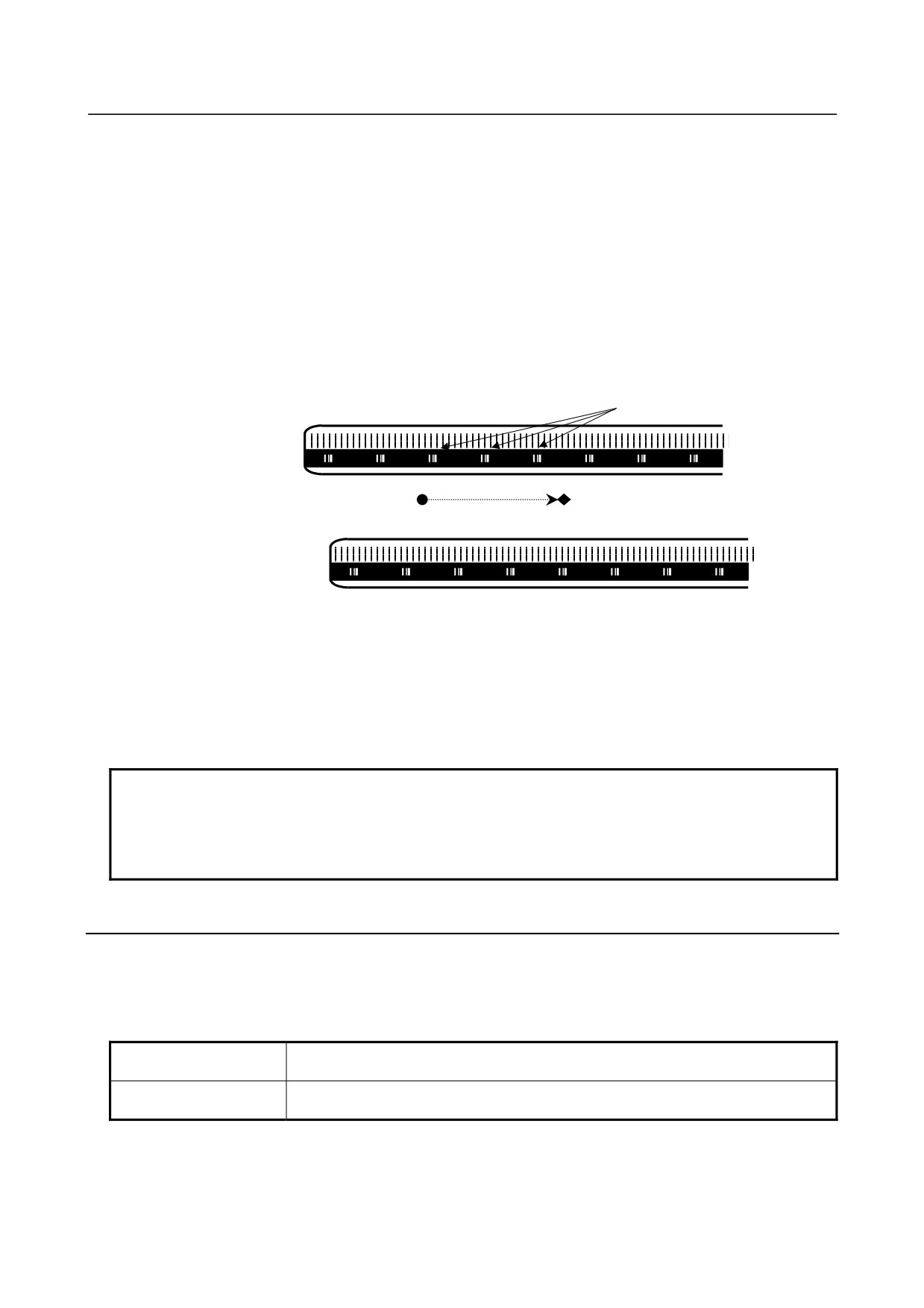
With axis synchronization control axes, a reference position is established as follows. When a reference
mark for the master or slave axis is detected, a stop takes place temporarily. Then, a feed operation is
performed again at the reference position return FL feedrate. This sequence is repeated until a reference
mark is detected three or four times for both the master and slave axes. Then the absolute position is
calculated for both the master and slave axes, and the reference position establish signals ZRF1, ZRF2, ...
<F120> are set to 1.
After the reference position has been established by the above operation, a synchronization error is
corrected. (Checking for excessive synchronization error alarm 2 is made even during reference position
establishment.)
(Example of 3 points measurement system)
Scale end
Reference mark
Master axis
(1)
(2)
(3)
Start point
End Point
Slave axis
In this example, reference mark (1) of the master axis is first detected, a pause takes place, movement
operation is performed at the FL feedrate, and a pause takes place again in a position where the reference
mark of the slave axis is detected.
Then, movement operation is performed again, reference mark (2) of the master axis, a pause takes place
when the reference mark of the slave axis, and reference mark (3) of the master axis are detected during
movement at the FL feedrate, and reference position establishment operation of both axes is completed on
the slave axis where the third reference mark is detected.
NOTE
In case of this function is used with axis synchronization control axes, if the value
of parameters Nos. 1883 and 1884 for both the master and slave axes is 0, the
reference position is not established. Also, the reference position establish signals
ZRF1, ZRF2, ... <F120> are set to 0.
3.6.5
Axis Control by PMC
In PMC axis control, if the reference position return command (axis control command code 05H) is issued for
an axis having a distance coded linear scale, reference position return is performed according to the reference
position return sequence for the distance coded linear scale.
Specifically, the following operations take place:
Before reference position The reference position is established by detecting two, three or four reference marks.
establishment
Movement to the reference position is not performed.
After reference position
Positioning at the reference position is performed.
establishment
- 352 -
B-64304EN/02
OPERATION
3.MANUAL OPERATION
3.6.6
Angular Axis Control
There are the following limitations when the angular axis control is used.
(a) It is necessary to use the linear scale with the distance coded reference mark for both the
perpendicular axis and the angular axis.
(b) When the reference point of the perpendicular axis is established, it is necessary to establish the
reference point of the angular axis previously. When the reference point of the angular axis is not
previously established, the alarm DS0020 is generated.
(c) During the reference point establishment operation of the angular axis, the command in the
perpendicular axis is invalid in the manual reference point return.
3.6.7
Note
(1) In the case of the actual interval of reference marks is different from parameter setting value, the
alarm DS1449 occurs.
(2) This function is disabled if any of the following conditions is satisfied:
•
Either parameter No.1821 (mark-1 interval) or parameter No.1882 (mark-2 interval) is set to 0.
•
The setting of parameter No.1821 is greater than or equal to the setting of parameter No.1882.
•
The difference between the settings made for parameters 1821 and 1882 is greater than or equal
to twice either setting.
•
The absolute-position detection function is enabled.(Bit 5 (APCx) of parameter No.1815 is set
to 1.)
(3) A difference of parameters Nos.1821 and 1882 must be more than 4.
Example)
When the scale, which is that mark1 interval is 20.000mm and mark2 interval is 20.004mm, is
used on IS-B machine :
When the detection unit of 0.001mm is selected, parameter No.1821 and No.1882 must be set
"20000" and "20004", and the difference of them is "4".
To use such a scale, please adjust the detection unit by modification of parameters No.1820
(CMR) and Nos.2084/2085(flexible feed gear) to make the difference of parameters Nos.1821
and 1882 more than 4 as following examples.
(a) Set the detection unit=0.0001mm, and set No.1821=200000, No.1882=200040
(b) Set the detection unit=0.0005mm, and set No.1821=40000, No.1882=40008
NOTE
When the detection unit is changed, parameters relating to the detection unit
(such as the effective area and positional deviation limit) must also be changed
accordingly.
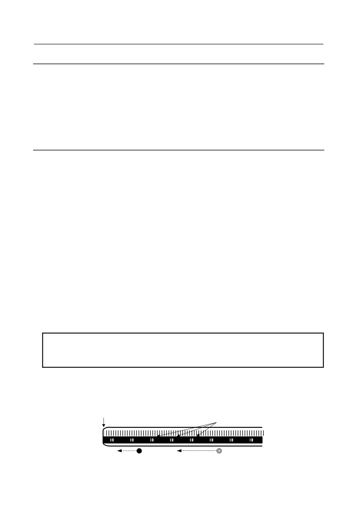
(4) In this procedure, the axis does not stop until two, three or four reference marks are detected. If
this procedure is started at the position near the scale end, CNC can not detect three or four reference
marks and the axis does not stop until over travel alarm occurs. Please care to start at the position
that has enough distance from scale end.
Scale end
Reference marks
Start point (Bad)
Start point (Good)
- 353 -
3.MANUAL OPERATION
OPERATION
B-64304EN/02
(5) When the axis used this function, the following function can not be used.
•
Absolute position detection (bit 5 (APCx) of parameter No.1815 = 1)
(6) If axial movement is made in the direction opposite to that of reference position return, the
movement is reversed to the direction of reference position return after three or four reference marks
have been detected. Steps (3) to (5) of the basic procedure for establishing a reference position are
carried out to establish the reference position.
M
(7) Simple straightness compensation
When the reference point establishment of moving axis is executed after the establishment of
compensation axis, the compensation axis is moved by simple straightness compensation amount
when the reference point of moving axis is established.
T
(8) The reference point establishment is not performed during synchronous control is activated.
(9) The reference point establishment is not performed during composite control is activated.
(10) The reference point establishment is not performed during superimposed control is activated.
3.7
LINEAR SCALE WITH DISTANCE-CODED REFERENCE
MARKS (SERIAL)
Overview
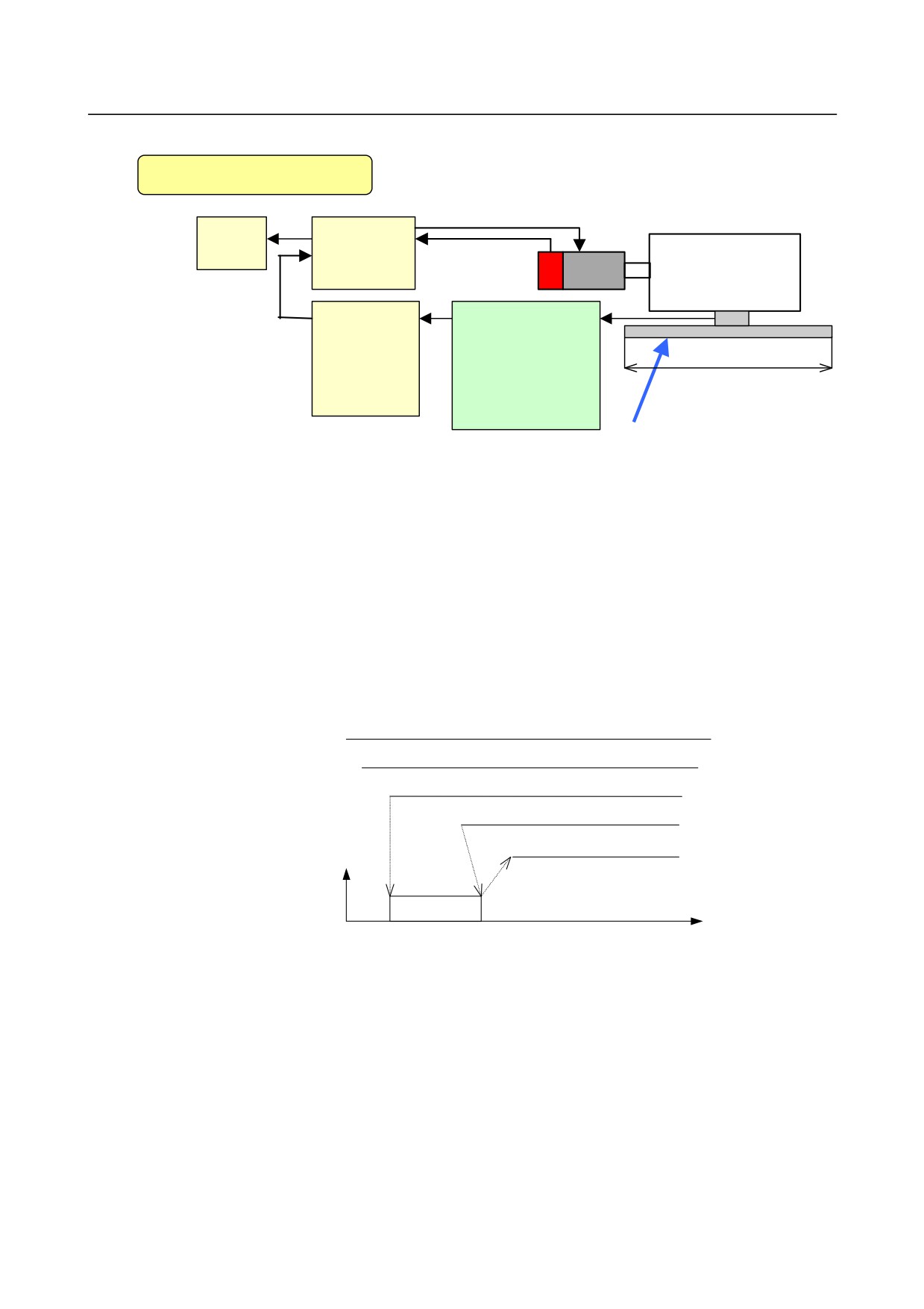
By using High-resolution serial output circuit for the linear scale with distance-coded reference marks
(serial), the CNC measures the interval of referenced mark by axis moving of short distance and
determines the absolute position.
This function enables high-speed high-precision detection by using High-resolution serial output circuit.
It is available that using maximum stroke 30 meters length.
Explanation
The linear scale with distance-coded reference marks (serial) is combined the irregular reference marked
linear scale with the High-resolution serial output circuit, it can detect the accurate position.
Reference mark signal
10.02
10.04
10.06
0
20
40
60
The CNC measures the interval of referenced mark by axis moving of short distance and determines the
absolute position, because of the interval of each reference mark is different with regular interval.
It is not necessary that the axis is moved to the reference position for establishment of reference position.
This function enables high-speed high-precision detection by using High-resolution serial output circuit.
It is available that using maximum stroke 30 meters length.
-
Connection
It is available under full closed system.
- 354 -
B-64304EN/02
OPERATION
3.MANUAL OPERATION
Full Closed System
CNC
Servo
Amplifier
Table
Separate
High
Detector
Resolution
Interface
Serial Output
Max. 30m
Unit
Circuit C
Linear scale with distance-coded
reference marks (serial)
-
Procedure for reference position establishment through manual operation
(1) Select the JOG mode, and set the manual reference position return selection signal ZRN to "1".
(2) Set a direction selection signal(+J1,-J1,+J2,-J2,…) for a target axis.
(3) The axis is fed at a constant low speed (reference position return FL feedrate specified by parameter
No.1425 setting).
(4) When the absolute position of linear scale with distance-coded reference marks (serial) is detected,
the axis stops. Then the absolute position of CNC is calculated and reference position establishment
signal (ZRF1,ZRF2,ZRF3,…) turns to "1".
The timing chart for this procedures is given below.
JOG
ZRN
+J1
Reference mark
ZRF1
Feedrate
FL rate
-
Procedure for reference position establishment through automatic operation
If an automatic reference position return (G28) is specified before a reference position is not established,
steps (3) to (4) above are performed automatically.
After the reference position is established, the automatic reference position return is performed by setting
of parameter RFS No.1818#0.
-
Stopping the operation for establishing a reference position
The operation for establishing a reference position is stopped if any of
the following operations is performed in steps (3) to (4), described above.
• Reset
• Setting the feed axis direction selection signal (+J1, -J1, +J2, -J2, etc.) to 0
• Setting the Servo off signals (SVF1, SVF2, etc.) to 1
- 355 -

3.MANUAL OPERATION
OPERATION
B-64304EN/02
If any of the following operations is performed during the operation of automatic reference position
return (G28) before a reference position is not established, the operation for establishing a reference
position stops:
• Reset
• Performing feed hold during movement from an intermediate position
• Setting the Servo off signals (SVF1, SVF2, etc.) to 1
If the operation for establishing a reference position is stopped by an operation other than a reset, the
operation for establishing a reference position must be reset and resumed.
-
Establishing a reference position and moving to the reference position
By following operation, establishing a reference position and moving to the reference position is
performed.
Moving through manual
Moving through automatic operation by automatic
operation in REF mode
reference position return (G28)
The reference
Establishing the reference
Firstly, moving to the intermediate position, and
position is not
position
establishing the reference position.
established.
Secondly, whether moving to the reference position or not
is performed by setting bit 0 (RFS) of parameter No.1818.
The reference
Moving to the reference position
Whether moving to the intermediate position and the
position is
reference position or not is performed by setting bit 1
established.
(RF2) of parameter No.1818.
-
Feed axis synchronization control
In case of using the axis synchronization control, please confirm the following items.
• When this function is used with axis synchronization control axes, the linear scale with
distance-coded reference marks (serial) used for the master axis and that used for the slave axis must
have reference marks placed at identical intervals.
• The master axis scale and the slave axis scale should be installed in parallel direction. (The zero
positions should be faced the same direction.)
• To the parameters, which relate to this function (except No.1883, No.1884), the same value must be
set for the master axis and for the slave axis.
• The linear scale with distance-coded reference marks (serial) should be applied for the master axis
and the slave axis.
If either of the master axis or the slave axis is not the linear scale with distance-coded reference
marks (serial), alarm DS0018 occurs when reference position establishment is tried.
• During operating the establishment of reference position, the state of signal for selecting
synchronized axis(SYNCn<Gn138> or SYNCJn<Gn140>) should be kept.
Procedure for reference position establishment by axis synchronization control is as follows.
• Both of axes (master axis and slave axis) are fed on the reference position return FL feedrate until
distance coded scales of both axes detect the absolute position.
• Then absolute position of both axes are calculated and Reference Position Establishment Signals
(ZRF1,ZRF2,...) turn to "1".
-
Angular axis control
In case of using the angular axis control, please confirm the following items.
• It is necessary to use the linear scale with distance-coded reference marks (serial) for both the
perpendicular axis and the angular axis.
If not, the alarm DS0019 occurs when reference position establishment is commanded.
• When the reference point establishment of angular and perpendicular axes are tried, please set bit 2
(AZR) of parameter No. 8200 to '0' and input signal NOZAGC <G063.5> to '0'.
If not, the alarm DS0019 occurs when reference position establishment is commanded.
- 356 -
B-64304EN/02
OPERATION
3.MANUAL OPERATION
• When the reference point of the perpendicular axis is established, it is necessary to establish the
reference point of the angular axis previously. When the reference point of the angular axis is not
previously established, the alarm DS0020 occurs.
• On angular axis control, if you use automatic setting of parameter No.1883,1884 on reference point
establishment
(bit
2 (DATx) of parameter No.1819 = 1), please establish reference point of
perpendicular axis after reference point establishment and return of angular axis.
In manual reference position return, the perpendicular axis cannot be specified while the angular axis
reference point is being established. The perpendicular axis, if specified, is ignored.
CAUTION
1 When the Linear scale with distance-coded reference marks (serial) is used,
please set bit 3 (SDCx) of parameter No.1818 to 1.
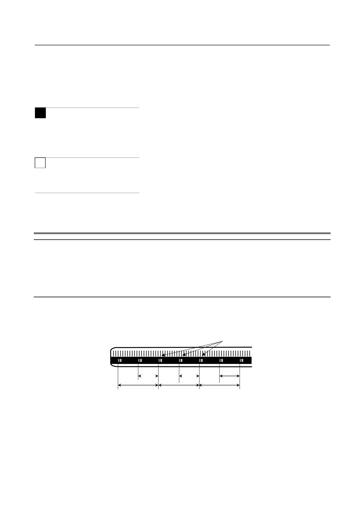
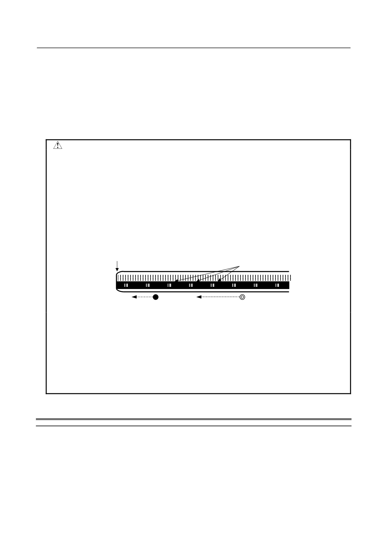
2 On the Linear scale with distance-coded reference marks (serial), the axis does
not stop until three reference marks are detected. If this procedure is started at
the position near the scale end, CNC can not detect three reference marks and
the axis does not stop until over travel alarm occurs. Please care to start at the
position that has enough distance from scale end.
And if establishment of reference position is failed, the establishment is retried.
Then axis does not stop until still more three reference marks are detected. So
please set the maximum move amount (detection unit : parameter No.14010) not
to reach the scale end.
Scale end
Reference marks
Start point (Bad)
Start point (Good)
3 Simple straightness compensation (M series)
When the reference point establishment of moving axis is executed after the
establishment of compensation axis, the compensation axis is moved by simple
straightness compensation amount when the reference point of moving axis is
established.
4 It is not available to use this function and the temporary absolute coordinate
setting together.
5 Angular axis control cannot be performed together with synchronous control (T
series), composite control (T series), or superposition control (T series).
3.8
MANUAL HANDLE RETRACE
Overview
In this function, the program can be executed both forward and backward with a manual handle (manual
pulse generator) under automatic operation.
Therefore, errors of a program, interference, and so on can be checked easily by working a machine
actually.
- 357 -

3.MANUAL OPERATION
OPERATION
B-64304EN/02
-
Checking mode
In this mode, the program can be executed forward and backward and the program can be checked.
To change to the checking mode, it is necessary to change the mode to the memory mode (MEM mode),
and the checking mode signal MMOD<Gn067.2> is set to "1". This function makes the data to execute
the program backward when the program is executed forward in the checking mode.
To work a machine synchronizing with a pulse generated by a manual handle in the checking mode, the
manual handle check signal MCHK <Gn067.3> is set to "1" in addition to the above-mentioned. As a
result, it becomes possible to check the program with a manual handle.
NOTE
During the checking mode, it is not possible to change the parameter and offset.
-
Forward movement with a manual handle
The "forward movement" is that the program is executed forward by turning a manual handle in the
positive direction (when the manual handle check signal is set to "1".) or in no relation to rotation of a
manual handle (when the manual handle check signal is set to "0".).
When the manual handle check signal is set to "1", the execution speed of the program is proportional to
the number of rotations of a manual handle. The program is executed forward rapidly when a manual
handle is turned to the positive direction rapidly. And, the program is executed forward slowly when a
manual handle is turned to the positive direction slowly. The distance magnification traveled per pulse
from manual handle can be switched as same as a usual manual handle feed function.
When the manual handle check signal is set to "0", the execution of the program is controlled as same as
an automatic operation.
-
Backward movement
The "backward movement " is that the program executed forward once is executed backward by turning a
manual handle in the negative direction.
The program can be executed backward only for the block executed forward. And, the number of blocks
for it is about 190 blocks. This block number changes by the content of the commanded program.
The program is executed backward rapidly when a manual handle is turned to the negative direction
rapidly. And the program is executed backward slowly when a manual handle is turned to the negative
direction slowly. The distance traveled per pulse from manual handle can switch magnification as well as
a usual manual handle feed.
Explanation
-
Control by the manual handle
Program execution start
The checking mode signal MMOD<Gn067.2> is set to "1" in the memory mode (MEM mode) in order to
change the checking mode. Then, the program execution is begun by turning ST signal from "1" to "0".
If the manual handle check signal MCHK <Gn067.3> is set to "1" at this time, the execution of the
program is controlled by a manual handle. The program is executed synchronizing with rotation of a
manual handle.
When a manual handle check signal MCHK<Gn067.3> is set to "0", it is controlled as usual execution.
When check mode signal MMOD<Gn067.2> is set to "1" during the operation of the program, it is
enabled a check mode from the block that next buffering is done.
That is, even if check mode signal set to "1", check mode is not always enabled at once.
When check mode is enabled, check mode confirmation signal MMMOD<Fn091.3> is set to "1".
NOTE
After the signal MMOD is turned to "0" during the execution of the program, the
program cannot be executed forward and backward.
- 358 -
B-64304EN/02
OPERATION
3.MANUAL OPERATION
Control with the manual handle
The value of the parameter No.6410 and the scale factors decide the moving speed of the machine by one
pulse generated by a manual handle.
When a manual handle is turned, the actual movement speed of the machine is as follows.
[Feedrate command value] × [Number of the handle pulse per a second]
× [Handle magnification] × ([Parameter setting value]/100) × (8/1000) (mm/min or inch/min)
Example)
When feedrate command value is 30mm/min, handle magnification is 100, parameter No.6410 is set
to 1 and manual pulse generator is rotated at 100 pulse/rev, the feedrate of axis is decided as follow.
[Feedrate]=30[mm/min] × 100[pulse/s] × 100 × (1/100) × (8/1000)[s] =24[mm/min]
When the feedrate exceeds the override 100% feedrate by turning a manual handle rapidly, the feedrate is
clamped at the speed of override 100%. That is, if the pulse of the following formula exceeds "1", the
feedrate is clamped.
[Number of the handle pulse per a second]
× [Handle magnification] × ([Parameter setting value]/100) × (8/1000)
The rapid traverse feedrate is clamped at 10%. However, the feedrate of the rapid traverse is clamped at
100% when bit 0 (HDRPD) of parameter No.6400 is set to "1".
And if parameter No.6405 is set to an optional value, it can be clamped to override by nearly optional
value.
When the parameter No.6405 is set to larger value than "100", it is clamped to nearly 100%.
When parameter No.6405 is set to "0", the setting of bit 0 (RPO) of parameter No.6400 becomes valid.
The single block signal and the feed hold signal are effective in the checking mode. When the execution
of a program is stopped by the single block stop or the feed hold stop, it is necessary to turn ST signal
from "1" to "0" in order to restart the program.
In the block with the movement and the block of dwell, the execution speed of the program can be
controlled by turning a manual handle. As for the block of neither movement nor dwell such as the block
of only address M, S, T, and F, the program advances to the following block even if a manual handle does
not turn.
The rotation of the spindle does not synchronize with a pulse of a manual handle. During the checking
mode, the spindle rotates at the specified rotation speed. As for the feed per revolution, a program is
executed at the feedrate which was converted from the rotation speed of the spindle to the corresponding
feed per minute inside CNC.
NOTE
The manual handle used by this function is always the first. The second and
third manual handles cannot be used.
Forward movement and backward movement with a manual handle
The program is executed forward when a manual handle is turned to the positive direction. And, the
program is executed backward when a manual handle is turned to the negative direction.
The program is executed backward as soon as a manual handle is turned to the negative direction in
executing the program forward.
When a manual handle keeps being turned in a negative direction, the program is executed backward and
the execution stops in the block of O number. Then, if a manual handle is turned to the positive direction,
the program is executed forward again.
Even if a manual handle controls the program execution, the program is executed forward in no relation
to a pulse generated by a manual handle on setting the manual handle check signal to "0".
Program end
When the block of M2 or M30 is executed, the manual handle retrace ends. It is not possible to execute
the program backward from the block of M2 or M30.
When the execution of the program ends, RESET signal must be set to "1", and the checking mode signal
and the manual handle check signal must be set to "0".
- 359 -
3.MANUAL OPERATION
OPERATION
B-64304EN/02
In 2 path control system, FIN signal must not be set to "1" when the block of M2 or M30 is executed in
only one of paths. After the block of M2 or M30 has been executed in both paths, FIN signal is set to "1".
(Except for the block of waiting M code is commanded before M2 or M30 in both paths.)
-
Notice of the operation
• Dry-run can not operate during the checking mode. Dry-run signal must be set to "0".
• Automatic operation starts immediately with the feedrate commanded by the program, when the
checking mode signal or the synchronous operation with handle signal is turned off during executing
the program in the checking mode.
• The edit of the program and the change of the parameter and the offset must not be done.
-
Backward movement of each code
All modal information of G, T, S-code is memorized in executing the program forward. And, the
memorized data of the modal G, T, S-code are used in executing the program backward.
As for M-codes, they are grouped and the modal information is managed by parameter No.6411 to 6490.
Therefore, M-code can be executed backward according to the information. As for the modal information
of the M-code, a change in each group is memorized in the execution data.
As for the codes except for G, M, S, and T, the same code is output between forward movement and
backward movement.
-
G-code
If G-code that changes modal information is commanded in backward movement, the modal information
of previous block is executed.
Example)
N1 G99 ;
N2 G01 X_ F_ ;
N3 X_ Z_ ;
N4 G98 ;
backward movement starts from this block
N5 X_ Y_ Z_ ;
If backward movement starts from N4 block, the modal information is changed from G98 to G99 and G99
is executed from N3.
G-code with a movement is traced along the route opposite to forward movement.
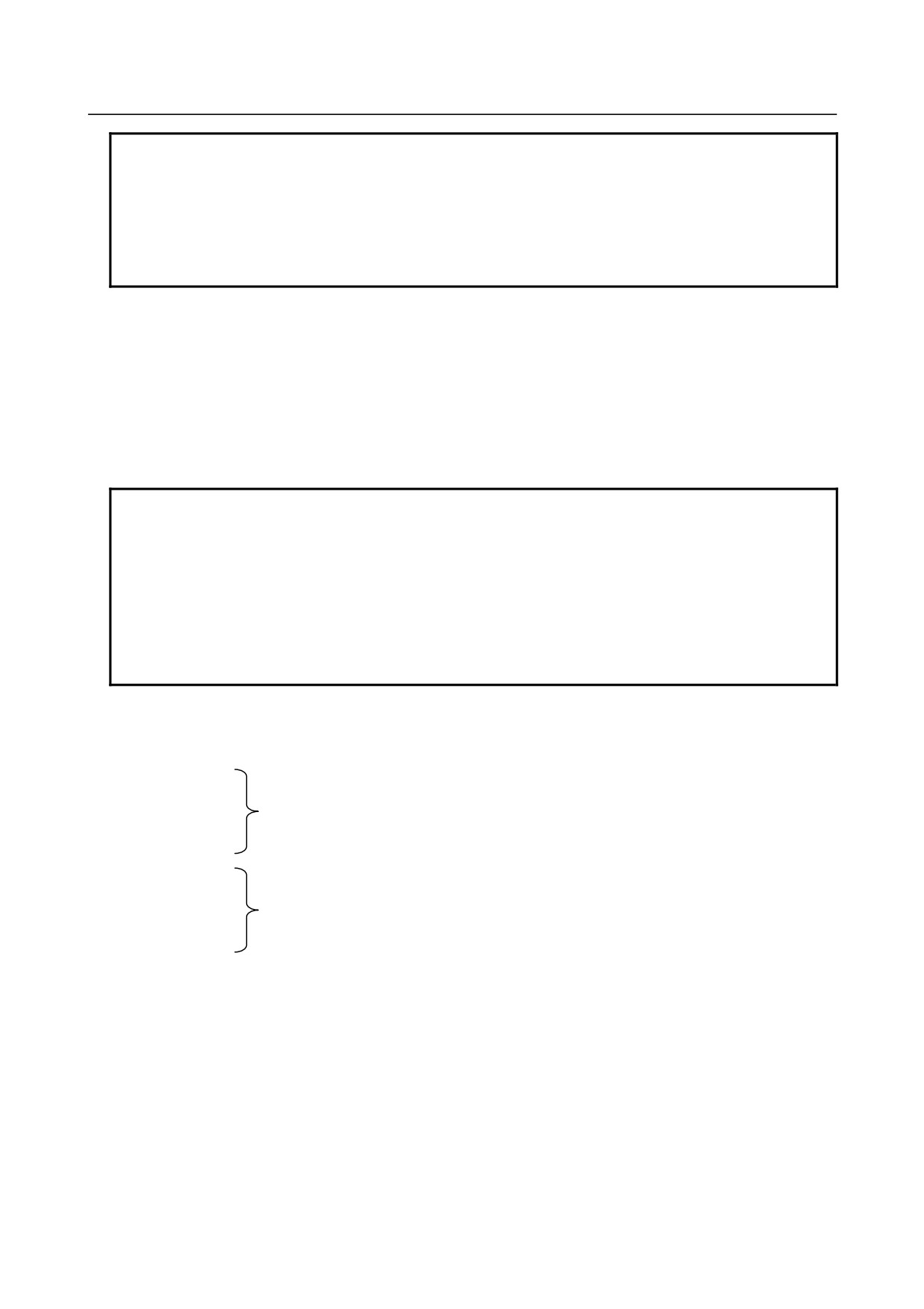
G-code that can be command in executing the program backward is as follows.
The other G-codes cannot be command in executing the program backward.
The G-codes in the G-code system B and C (for T series) also can be used.
T series (for G-code system A)
G00 G01 G02 G03 G04 G22 G23
G25 G26 G28 G30 G40 G41 G42
G50 G53 G65 G70 G71 G72 G73
G75 G80 G83 G85 G87 G89 G90
G94 G96 G97 G98 G99
M series
G00 G01 G02 G03 G04 G22 G23
G25 G26 G28 G30 G40 G41 G42
G43 G44 G49 G53 G65 G73 G76
G80 G81 G82 G83 G85 G86 G87
G88 G89 G82 G94 G95 G96 G97
- 360 -
B-64304EN/02
OPERATION
3.MANUAL OPERATION
NOTE
1 In Small-Hole Pecking Drilling Cycle(G83) (M series), backward movement is
prohibited.
2 In forward movement of Boring Cycle(G88) (M series), the sequence of actions
at bottom of hole is shown as follows (dwell -> stop of spindle motor -> hold
state). But in backward movement, that is (rotation of spindle -> hold state ->
dwell after restart).
-
M-code
If there is M-code in the same group is commanded in previous blocks, modal information of the M-code,
commanded at the last in previous blocks, is output.
If no M-code is commanded in previous blocks, the M-code set to the first parameter in the same M-code
group is output.
If M-code is not set to group M-code in parameter, the same M-code is output in backward movement.
If the parameter RVN(6400#5) is set to "1", the backward movement is prohibited when the M-code,
which is not set to group M-code, is commanded in backward movement.
NOTE
When setting the parameter RVN, backward movement prohibition is enabled
except the M-code which was set in the grouping but backward movement can
be enabled for the following M-code exceptionally.
1. Subprogram Call by M98/M99.
2. Subprogram Call using an M code
3. Macro Call using an M code
4. Waiting M code
5. M0
Example) Output of M-codes that are set to groups by parameters in backward movement
Setting of parameters:
No.6400#2=1, #3=0 (5 M-codes/group and 16 groups)
No.6411=100
No.6412=101
Group A
No.6413=102
No.6414=103
No.6415=104
No.6416=200
No.6417=201
Group B
No.6418=202
No.6419=203
No.6420=204
Program O10 is executed in forward movement from N1 to N15 and backward movement is executed
from N15. In backward movement, the output of M-codes is shown as next table.
- 361 -

3.MANUAL OPERATION
OPERATION
B-64304EN/02
Forward movement
Backward movement
O0010 ;
N1 G4 X1. ;
N2 M101 ;
M101
M100 (*1)
N3 G4 X1. ;
N4 M204 ;
M204
M200 (*1)
N5 G4 X1. ;
N6 M104 ;
M104
M101 (*2)
N7 G4 X1. ;
N8 M300 ;
M300
M300 (*3)
N9 G4 X1. ;
N10 M200 ;
M200
M204 (*2)
N11 G4 X1. ;
N12 M0 ;
M0
M0 (*3)
N13 G4 X1. ;
N14 M102 ;
M102
M104 (*2)
N15 G4 X1. ;
Backward movement starts from this block
M2 ;
*1 No M-code in the same group is commanded before this block, so the M-code, which is set in the 1st.
parameter of the same group, is output.
*2 M-code in the same group is commanded before this block, so the M-code, which is commanded at
the last before this block, is output.
*3 M-code is not set to group M-code, so the same M-code is output.
-
S and T-code
A modal value of the previous block is output.
When movement command and S-code or T-code is commanded in the same block, the timing of the
output of the S-code and T-code is different. Because, the timing where S-code and T-code are output at
the forward movement is different from that at the backward movement. By setting bit 7 (STO) of
parameter No.6401 to "1", the timing of the output of S and T code at the forward movement is the same
as the one at the backward movement.
Example)
T-code output timing at the backward movement
T-code is output as follows when the program proceeds backward after the forward movement to N8
block.
Backward movement
Forward movement
Parameter STO=0
Parameter STO=1
O1000 ;
N1 G98 G00 X0 Z0 ;
Default T output
N2 G00 X-10. T11 ;
T11 output
Default T output
N3 G00 X100. ;
T11 output
N4 G00 X10. Z20. T22 ;
T22 output
T11 output
No T code output
N5 G00 X30. Z30. ;
N6 G00 X-10. Z-20. ;
T22 output
N7 G00 X50. Z40. T33 ;
T33 output
T22 output
T33 output
N8 G04 X5. ;
(Backward start)
(Backward start)
M30 ;
The “Default T” means a T-code status at N1 block in forward movement. If the status is T0, “T0”
signal is output as “Default T” in the backward movement.
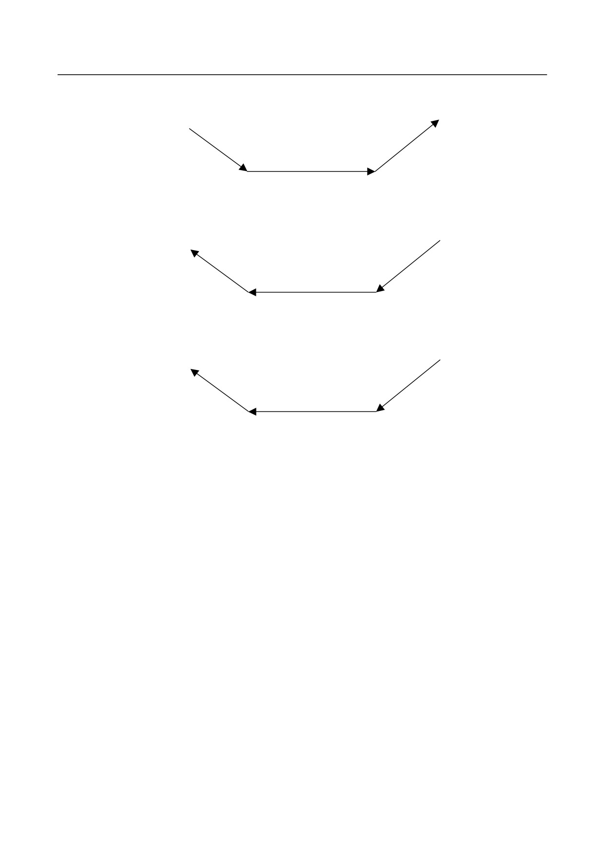
The timing of T-code output of N7 and N8 in O1000 shown in the example above is as follows.
- 362 -
B-64304EN/02
OPERATION
3.MANUAL OPERATION
Forward movement :
N6
with T22
N7
N8
T33 output
Backward movement (When parameter STO is set to “0”) :
N6
N8
N7
T22 output
Backward movement (When parameter STO is set to “1”) :
N6
N8
N7
T22 output
T33 output
-
Direction change prohibition
The direction change prohibition is a state not changing the direction where the program is executed.
In the state, even if the rotating direction of a manual handle is reversed, the reversed rotation is ignored.
A manual handle must be rotate in the same direction as present direction for removing this state.
The direction change prohibition can be confirmed by output signal MNCHG<Fn091.1>.
It becomes the change prohibition state under the following condition.
• During axis movement
• While the block with the code waiting for FIN is executing
• After a block has done and until the next block begins to operate
• During thread cutting
• Modal G code of G68 (M series) and G51.2 (T series)
• The block with the axis that ends movement earlier in the block with G02 or nonlinear type position
(G00) etc.
• During waiting at a block boundary (Only for a 2-path system. See "Waiting in 2-path system".)
-
Backward movement prohibition
The backward movement prohibition is a state that the program cannot be executed from a certain block
backward. In this state, the negative rotation of a manual handle is ignored, and the only positive rotation
is effective. The program must be executed forward by rotating a manual handle in the positive direction
for removing this state.
The backward movement prohibition can be confirmed by output signal MRVSP<Fn091.2>.
If the following blocks are executed in backward movement, backward movement is prohibited.
• Program number block of main program (except subprogram and macro program)
• Over the maximum number of the blocks for reverse movement
- 363 -
3.MANUAL OPERATION
OPERATION
B-64304EN/02
• The block including backward movement prohibition G-code (which is not described in the
paragraph "G-code")
• The block which is executed while in modal including backward movement prohibition G-code
(which is not described in the paragraph "G-code")
-
Status display
In manual handle retrace, the status of manual handle retrace is displayed on clock display of CNC state
display line. This status display is displayed during the execution of manual handle retrace. The clock is
displayed usually.
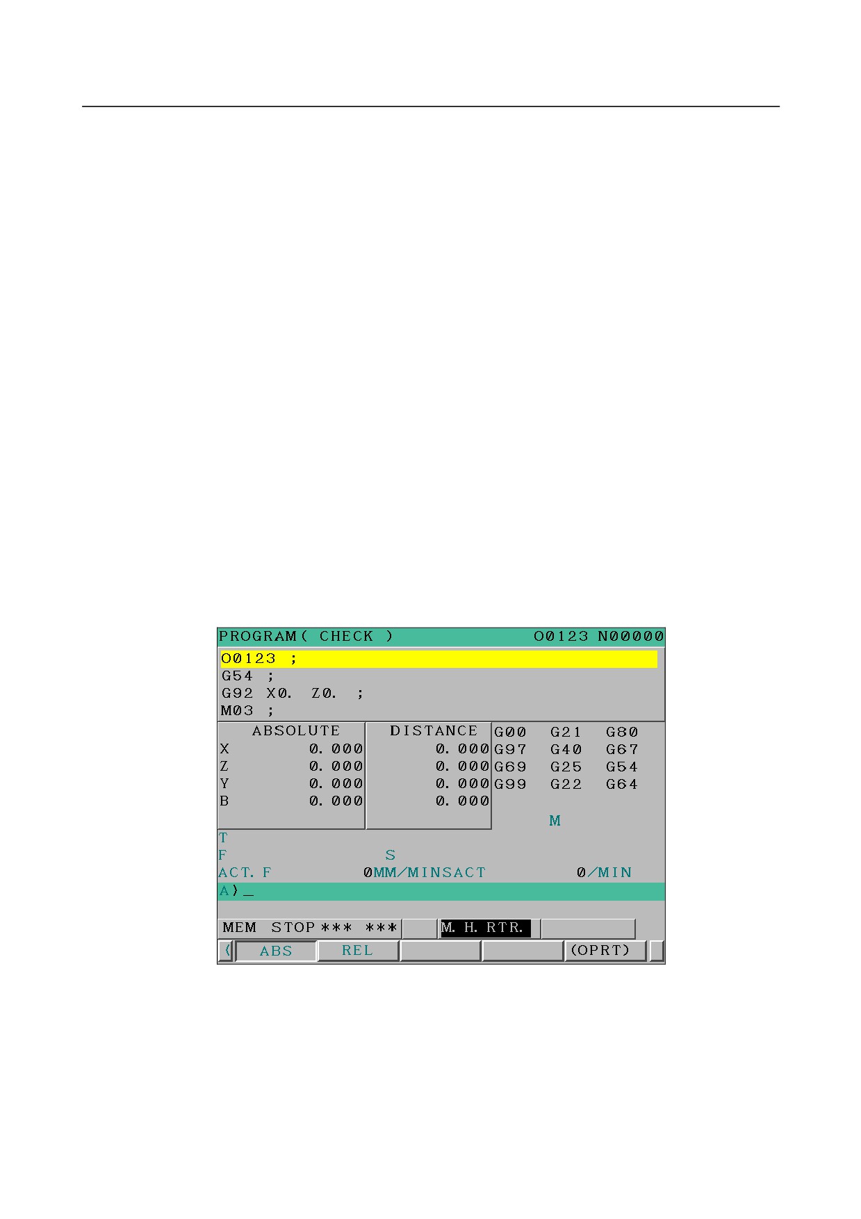
When the all condition is filled, "M.H.RTR." is displayed on clock display of CNC state display line. This
status is displayed by the color of color setting 3 (INPUT KEY, O/N NO. and STATUS are the same
color). The screen display is as shown in Fig.3.8(a). When the following conditions are not full, the clock
is displayed.
• When bit 2 (CHS) of parameter No.6401 is set to "0":
1)
Software option of handle manual retrace is enabled.
2)
Status display disable/enable bit 6 (HST) of parameter No.6401 is set to "1".
3)
Check mode confirmation signal MMMOD<Fn091.3> is set to "1".
• When bit 2 (CHS) of parameter No.6401 is set to "1":
1)
Software option of handle manual retrace is enabled.
2)
Status display disable/enable bit 6 (HST) of parameter No.6401 is set to "1".
3)
Cycle start signal STL<Fn000.5> is set to "1".
4)
Check mode signal MMOD<Gn067.2> is set to "1".
5)
Manual handle check signal MCHK<Gn067.3> is set to "1".
Fig. 3.8 (a) "M.H.RTR." status display
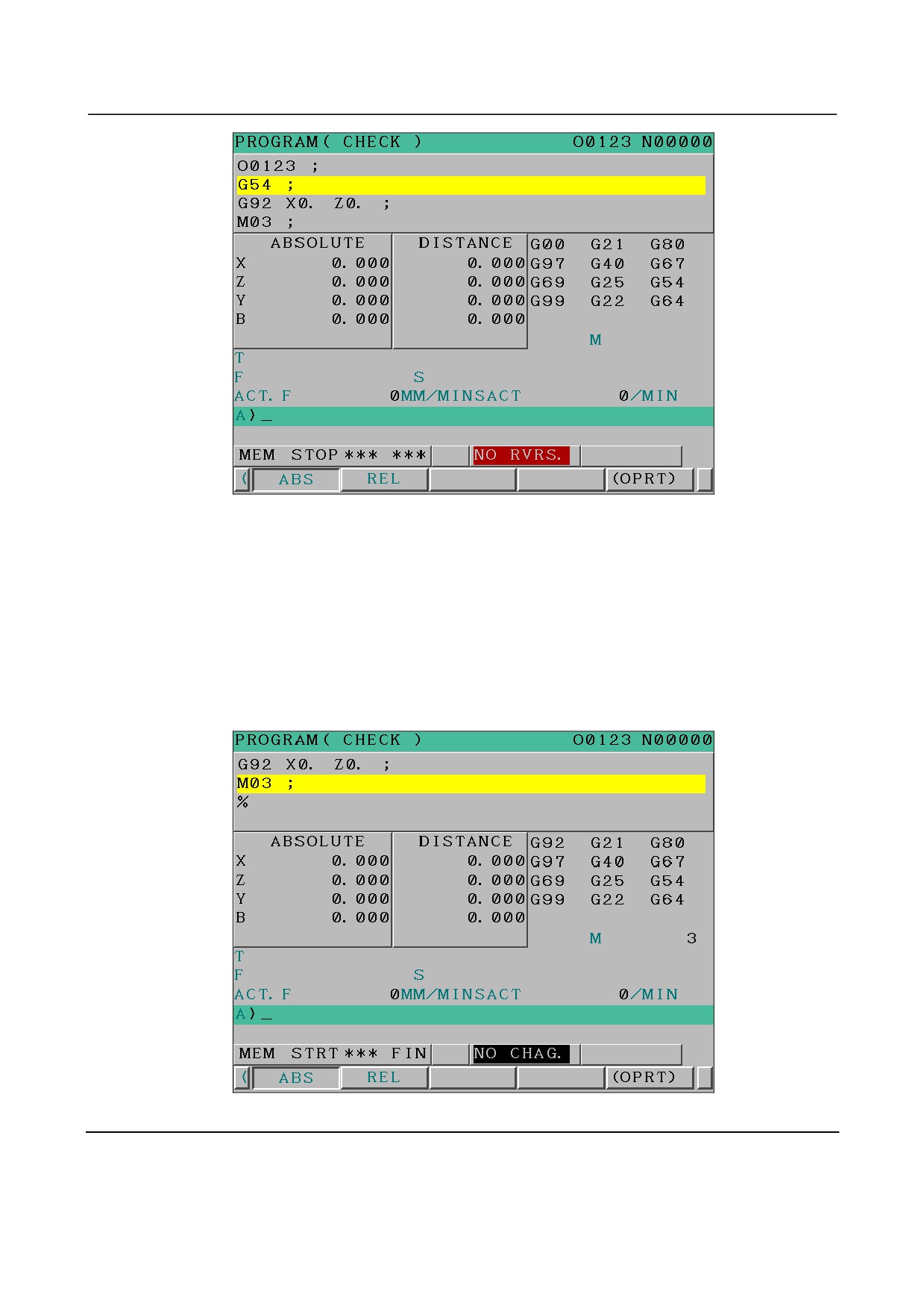
Besides, when reverse movement prohibition signal MRVSP<Fn091.2> is set to "1",
the "NO RVRS." is displayed. This status is displayed by blinking/reversing in the color of color number
1 (ALARM is the same color). The screen display is as shown in Fig.3.8(b). When reverse movement
prohibition signal MRVSP<Fn091.2> is set to "0", the " M.H.RTR." is displayed again.
- 364 -
B-64304EN/02
OPERATION
3.MANUAL OPERATION
Fig. 3.12 (b) " NO RVRS." status display
Besides, when direction change prohibition signal MNCHG<F0091.1> is set to "1" and the direction of
program’s execution is changed by manual handle, this status display changes from "M.H.RTR." to
"NO.CHAG.".
This status is displayed by blinking/reversing in the color of color number 3
(INPUT KEY, O/N NO.
and STATUS are the same color) . The screen display is shown as Fig.3.12(c). When the program is
executed in the direction as the same as before by manual handle or direction change prohibition signal
MNCHG<Fn091.1> is set to "0", the " M.H.RTR." is displayed again.
Moreover, when parameter FWD(No.6400#1) is set to "1" and the program is executed to change
direction by manual handle, this status display changes from "M.H.RTR." to "NO.CHAG.".
Fig. 3.12 (c) "NO.CHAG." status display
Limitation
-
Movement in automatic operation by DNC operation mode(RMT)
In the automatic operation by DNC operation mode(RMT), the backward movement is prohibited though
the forward movement is enable.
- 365 -