FANUC Series 0i-MODEL D, Series 0i Mate-MODEL D. OPERATOR'S MANUAL - page 11
17.AXIS CONTROL FUNCTIONS PROGRAMMING
B-64304EN/02
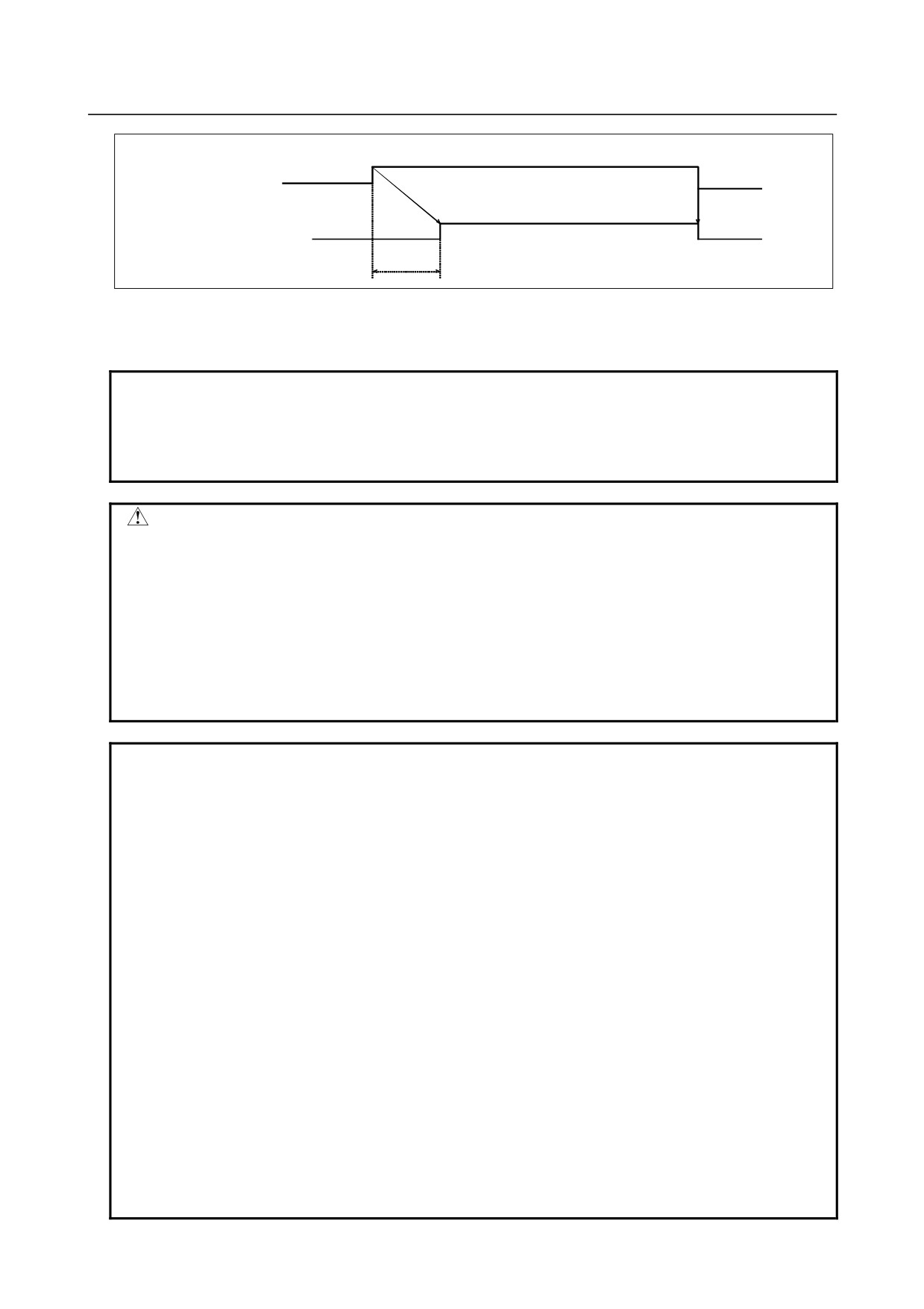
SA<F000#6>
1
0
Alarm detection function Enabled
Disabled
Setting of parameter No. 8327
(512 msec when this parameter is not set)
Fig. 17.1.6 (b) Timing chart
When the servo ready signal SA <F000.6> is set to 0, torque difference alarm detection is disabled.
NOTE
The servo axis number combination of the master axis and slave axis
synchronized with each other must be such that an odd servo axis number is
assigned to the master axis and the next servo axis number is assigned to the
slave axis like (1,2) and (3,4).
CAUTION
1 When making a synchronous error check, ensure that the reference position on
the master axis and the reference position on the slave axis must be at the same
position.
2 In manual reference position return operation, the same operation is performed
along the master axis and slave axis until a deceleration operation starts. After
a deceleration operation starts, grid detection is performed for the master axis
and slave axis independently of each other.
3 Pitch error compensation and backlash compensation are performed for the
master axis and slave axis independently of each other.
NOTE
1 During axis synchronous control, a movement based on the reference position
return check (G27), automatic reference position return (G28), 2nd/3rd/4th
reference position return (G30), or machine coordinate system selection (G53)
command is made as described below according to the setting of bit 7 (SRF) of
parameter No. 8304.
<1> When SRF = 0, the same movement as made along the master axis is made
along the slave axis.
<2> When SRF = 1, a movement is made along the slave axis to the specified
position independently of a movement made along the master axis to the
specified position.
2 A command not involving a movement along an axis such as the workpiece
coordinate system setting command and local coordinate system setting
command is set with the master axis according to the master axis programming.
3 During synchronous operation, the signals provided for each axis, such as the
external deceleration, interlock, and machine lock signals, are enabled only on
the master axis side and ignored on the slave axis side.
4 When switching the synchronization state in a program, be sure to specify M
codes (parameter No. 8337 and No. 8338) for turning synchronization on and
off. By switching between the input signals SYNCx <G138> and SYNCJx
<G140> from the PMC with the M codes, the synchronization state can be
switched in the program.
- 276 -
B-64304EN/02
PROGRAMMING
17.AXIS CONTROL FUNCTIONS
NOTE
5 When controlled axis removal is performed, the synchronization state is
cancelled. When performing controlled axis removal, perform removal for the
master axis and slave axis at the same time.
6 If a programmed command is specified for the slave axis during synchronous
operation, an alarm PS0213 is issued.
A programmed command can be specified for the slave axis when switching
between synchronous operation and normal operation is set to 0 (with bit 5
(SCA) of parameter No. 8304 set to 0) to select normal operation.
7 Axis synchronous control and PMC axis control cannot be used at the same
time.
17.2 ROTARY AXIS ROLL-OVER
Overview
The roll-over function prevents coordinates for the rotary axis from overflowing. The roll-over function is
enabled by setting bit 0 (ROAx) of parameter No. 1008 to 1.
Explanation
For an incremental programming, the tool moves the angle specified in the command. For an absolute
programming, the coordinates after the tool has moved are values set in parameter No. 1260, and rounded
by the angle corresponding to one rotation. The tool moves in the direction in which the final coordinates
are closest when bit 1 (RABx) of parameter No. 1008 is set to 0. Relative coordinates can be rounded to
the angle corresponding to one rotation by setting bit 2 (RRLx) of parameter No. 1008 is set to 1.
Example
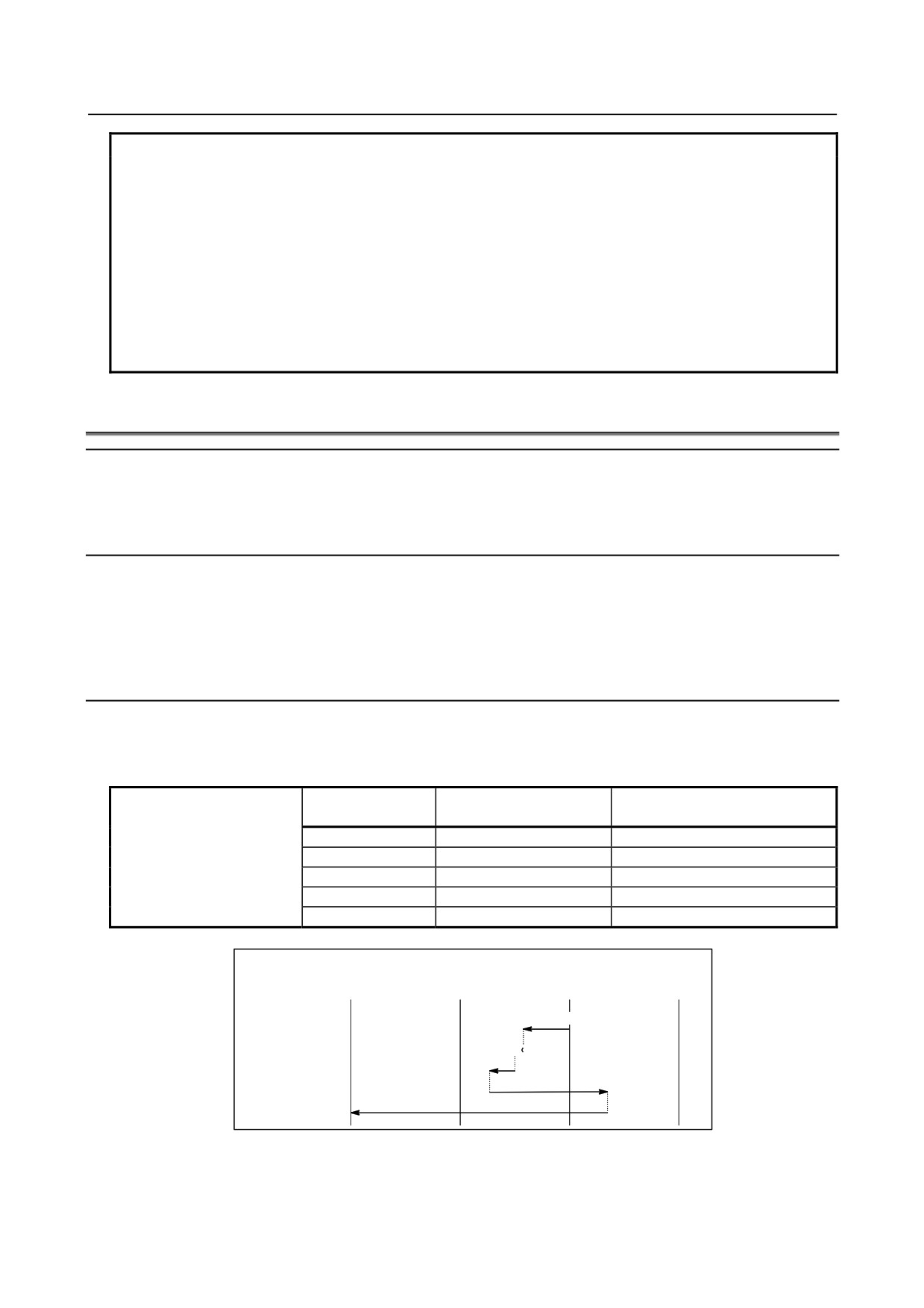
Assume that axis A is the rotary axis and that the amount of movement per rotation is 360.000 (parameter
No. 1260). When the following program is executed using the roll-over function of the rotary axis, the
axis moves as shown below.
Absolute coordinate value after
Sequence number
Actual movement value
G90 A0 ;
movement end
N1 G90 A-150.0 ;
N1
-150
210
N2 G90 A540.0 ;
N2
-30
180
N3 G90 A-620.0 ;
N3
-80
100
N4 G91 A380.0 ;
N4
+380
120
N5 G91 A-840.0 ;
N5
-840
0
Relative
coordinate value
-720°
-360°
-0°
360°
Absolute
-0°
-0°
-0°
-0°
coordinate value
210° (Absolute)
N1
180°
N2
100°
N3
120°
N4
N5
- 277 -
17.AXIS CONTROL FUNCTIONS PROGRAMMING
B-64304EN/02
M
NOTE
This function cannot be used together with the index table indexing function.
17.3 ARBITRARY ANGULAR AXIS CONTROL
Overview
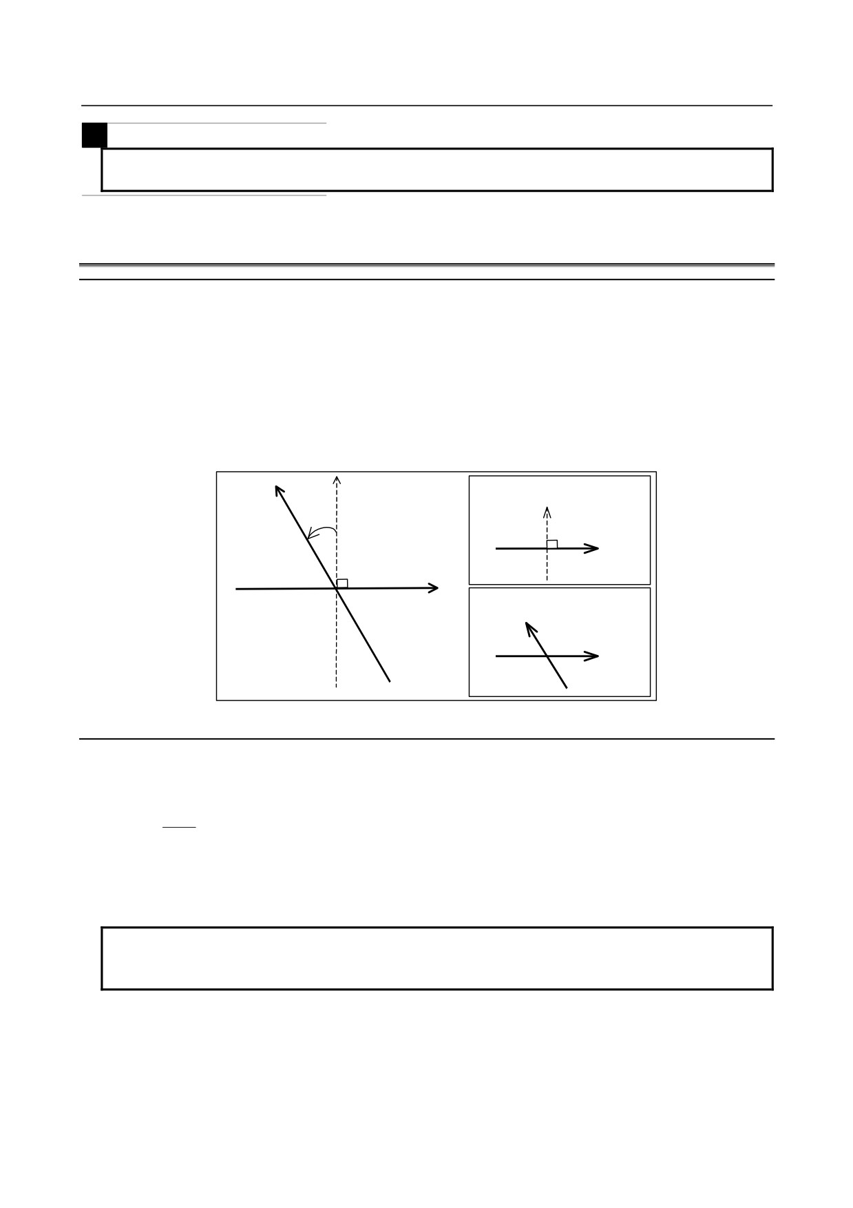
When the angular axis installed makes an angle other than 90° with the perpendicular axis, the Arbitrary
angular axis control function controls the distance traveled along each axis according to the inclination
angle as in the case where the angular axis makes 90° with the perpendicular axis.
Arbitrary axes can be specified as a set of an angular axis and perpendicular axis by parameter setting.
The actual distance traveled is controlled according to an inclination angle. However, a program, when
created, assumes that the angular axis and perpendicular axis intersect at right angles. The coordinate
system used at this time is referred to as the program coordinate system.
(The program coordinate
system may be referred to as the Cartesian coordinate system, and the actual move coordinate system may
be referred to as the angular coordinate system or machine coordinate system.)
Program coordinate system
+Y'(Hypothetical axis)
(Cartesian coordinates)
+Y'
θ
+Y'(Angular axis)
+X
+X(Perpendicular axis)
Machine coordinate system
(Angular coordinates)
+Y
θ: Inclination angle
+X
Fig. 17.3 (a)
Explanation
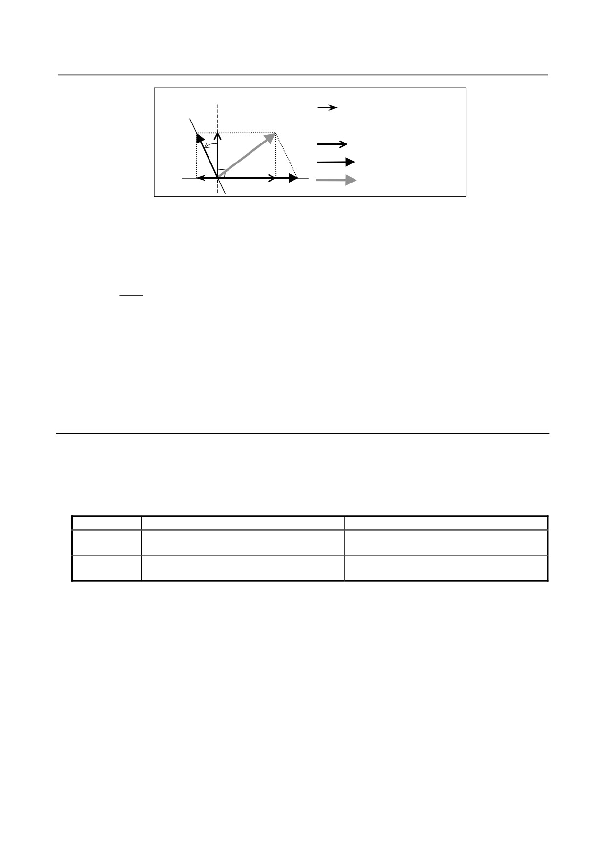
When the amounts of travel along the angular axis and the perpendicular axis are Ya and Xa, respectively,
the amounts are controlled according to the formulas shown below.
Yp
Xa,Ya: Actual distance
Ya =
cos θ
Xp,Yp: Programmed distance
The amount of travel along the perpendicular axis is corrected by the influence of travel along the angular
axis, and is determined by the following formula:
Xa = Xp - C × Yp × tanθ
NOTE
The coefficient C is 1/2 in the case of diameter specification for the
perpendicular axis (X) or 1 in the case of radius specification.
- 278 -
B-64304EN/02
PROGRAMMING
17.AXIS CONTROL FUNCTIONS
+Y' (Hypothetical axis)
Yp tanθ (perpendicular axis
+Y (Angular axis)
component produced by
travel along the angular axis)
θ
Xp and Yp
Xa and Ya
Actual tool travel
+X (Perpendicular axis)
Fig. 17.3 (b)
-
Feedrate
When the Y-axis is an angular axis, and the X-axis is a perpendicular axis, the feedrate along each axis is
controlled as described below so that the feedrate in the tangent direction becomes Fp.
The feedrate component along the Y-axis is determined by the following expressions:
Fa represents the actual feedrate.
Fp
Fay =
Fp represents a programmed feedrate.
cos θ
Fax = Fp - Fp × tanθ
-
Absolute and relative position display
An absolute and a relative position are indicated in the programmed Cartesian coordinate system.
-
Machine position display
A machine position indication is provided in the machine coordinate system where an actual movement is
taking place according to an inclination angle.
Method of use
The angular and perpendicular axes for which arbitrary angular axis control is to be applied must be
specified beforehand, using parameters Nos. 8211 and 8212. When 0 is set in one of the parameters, the
same number is specified in the parameters, or a number other than the controlled axis numbers is
specified in a parameter, however, an angular axis and perpendicular axis are selected according to the
table below.
Angular axis
Perpendicular axis
Y-axis of the basic three axes (axis with 2 set in
Z-axis of the basic three axes (axis with 3 set in
M series
parameter No. 1022)
parameter No. 1022)
X-axis of the basic three axes (axis with 1 set in
Z-axis of the basic three axes (axis with 3 set in
T series
parameter No. 1022)
parameter No. 1022)
• Bit 0 (AAC) of parameter No. 8200 enables or disables the arbitrary angular axis control. If the
function is enabled, the distance traveled along each axis is controlled according to an angular angle
parameter No. 8210.
• By using bit 2 (AZR) of parameter No. 8200, whether to make a movement along the perpendicular
axis by a movement made along the angular axis when a manual reference position return operation
is performed along the angular axis can be chosen.
• By setting the normal axis/angular axis control invalid signal NOZAGC to 1, angular axis control
only for the angular axis can be available. In this time the angular axis are converted to those along
the angular coordinate system without affecting commands to normal axis.
Use this signal when operating each axis independently.
-
Manual reference position return operation
A movement is made to the reference position (machine position) set in parameter No. 1240. By using
bit 2 (AZR) of parameter No. 8200, whether to make a movement along the perpendicular axis when a
reference position return operation is performed along the angular axis can be chosen.
- 279 -
17.AXIS CONTROL FUNCTIONS PROGRAMMING
B-64304EN/02
-
Automatic reference position return operation (G28, G30)
A movement to the middle point along the angular axis affects a movement along the perpendicular axis.
As a movement from the middle point to the reference position along the angular axis, a selection can be
made with bit 0 (ARF) of parameter No. 8209 between a Cartesian coordinate system operation (FS0i-C
compatibility) and an angular coordinate system operation. If manual reference position return operation
is not performed even once after the power is turned on, operation is performed in the same sequence as
for manual reference position return operation. So, specify commands first for the angular axis then for
the perpendicular axis.
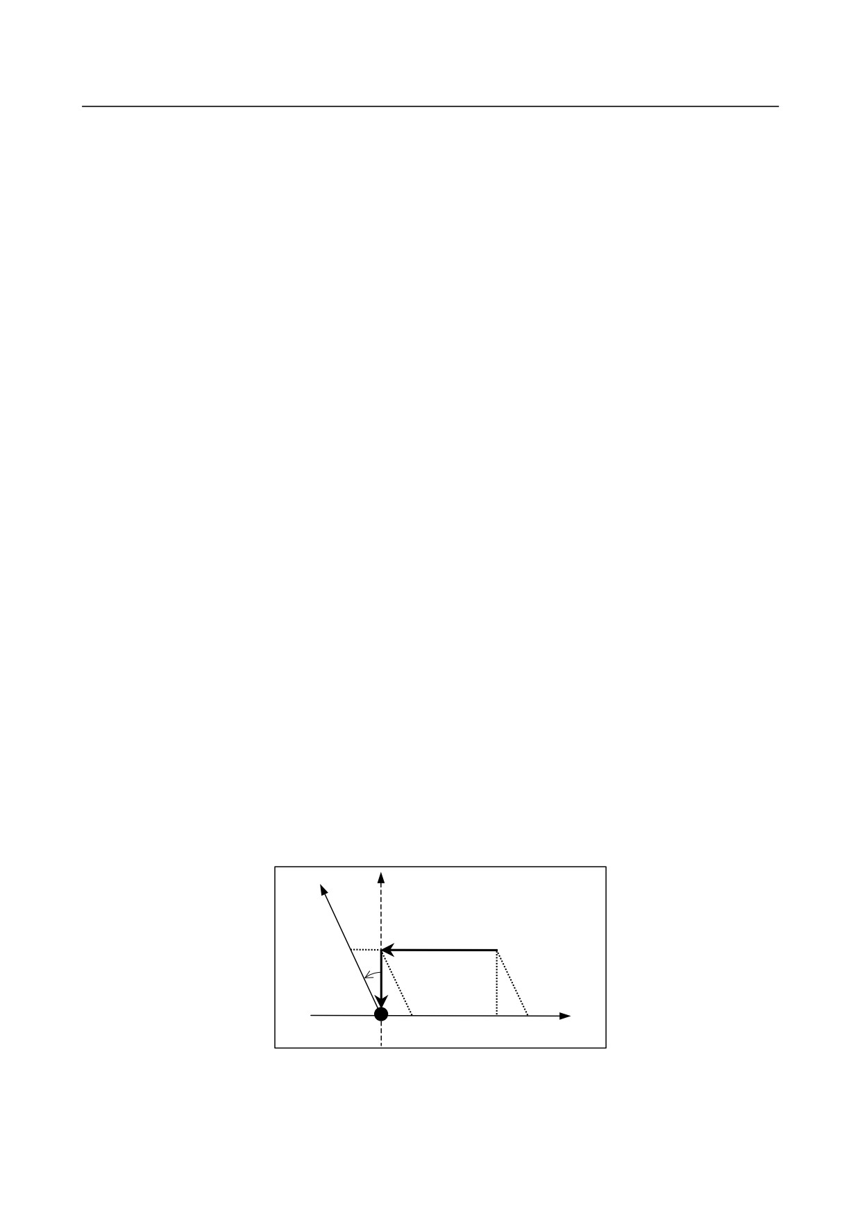
Example 1)
When the Y-axis is an angular axis and the X-axis is a perpendicular axis
(1) If the angular axis is first specified then the perpendicular axis is specified, reference position
return operation is performed normally.
G28 Y_ ;
G28 X_ ;
(2) If the perpendicular axis is first specified then the angular axis is specified, or if the
perpendicular axis and the angular axis are specified at the same time, alarm PS0372 is issued
when a movement is made along the perpendicular axis.
⎧G28X_; or
⎧G28X_Y_;
⎨
⎨
⎩G28Y_;
⎩
Example 2)
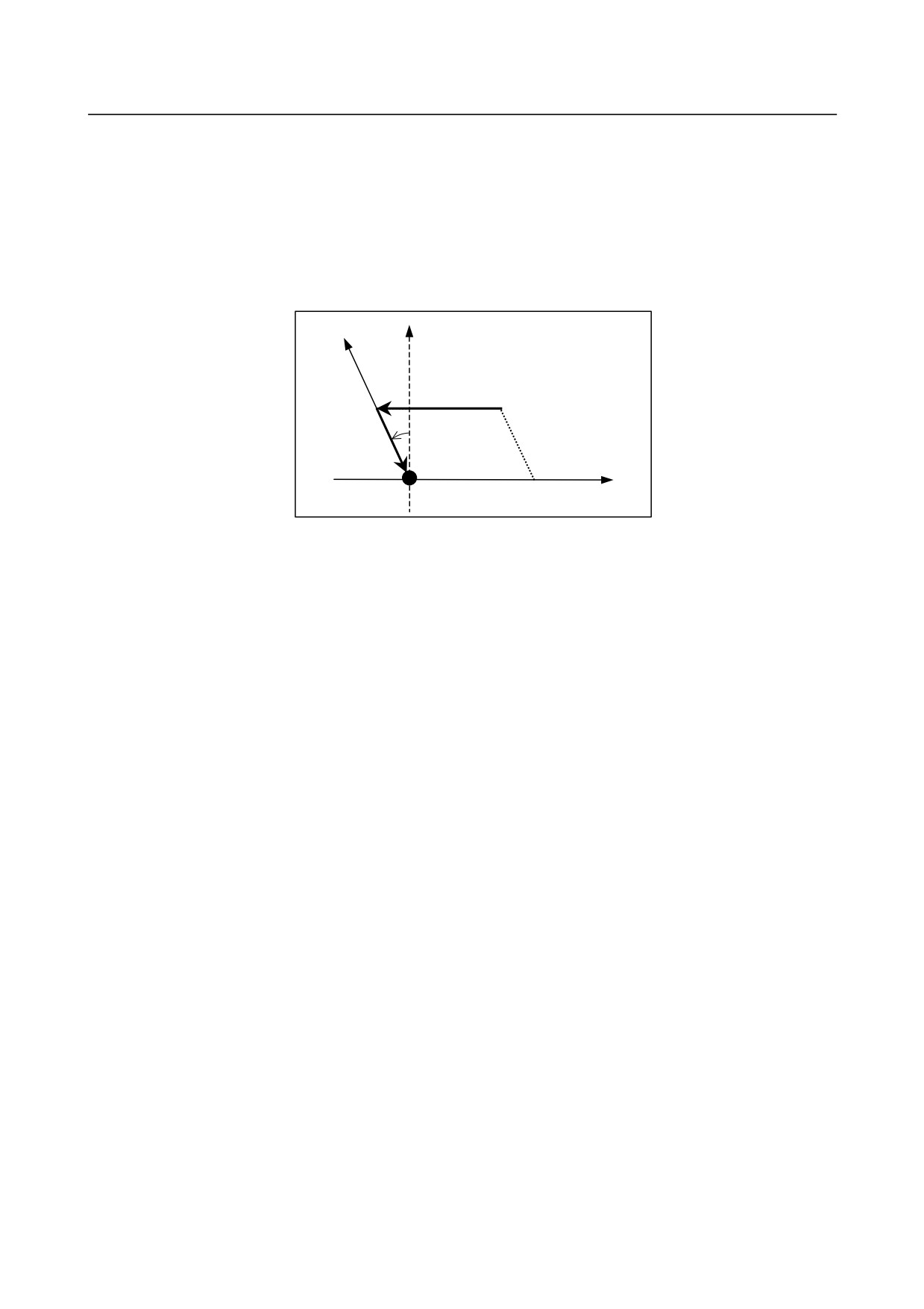
Automatic reference position return examples
(If the Y-axis is an angular axis, the X-axis is a perpendicular axis, and the inclination angle is -30.
This example assumes that the reference position is already established once.)
<1> Command for automatic reference position return along the Y-axis from point P2
>G91 G28 X200. ;
<2> Command for automatic reference position return along the X-axis from point P1
>G91 G28 Y100. ;
(1) If bit 0 (ARF) of parameter No. 8209 is 1 (FS0i-C compatibility)
<1> Coordinates at P1
(Absolute coordinate)
(Machine coordinate)
X
0.000
X
57.735
Y
100.000
Y
115.470
<2> Coordinates at P0
(Absolute coordinate)
(Machine coordinate)
X
0.000
X
0.000
Y
0.000
Y
0.000
+Y (Angular axis)
+Y' (Hypothetical axis)
P1
P2
115.470
30°
+X
(Perpendicular
axis)
P0(0,0)
57.735
200
257.735
- 280 -
B-64304EN/02
PROGRAMMING
17.AXIS CONTROL FUNCTIONS
(2) If bit 0 (ARF) of parameter No. 8209 is 0
<1> Coordinates at P1
(Absolute coordinate)
(Machine coordinate)
X
0.000
X
0.000
Y
100.000
Y
115.470
<2> Coordinates at P0
(Absolute coordinate)
(Machine coordinate)
X
0.000
X
0.000
Y
0.000
Y
0.000
+Y(Angular axis)
+Y’(Hypothetical axis)
P1
P2
115.470
30°
+X(Perpendicular
axis)
P0(0,0)
200
-
Reference position return operation of high-speed type
When a reference position is already established and a reference position return operation of high-speed
type is to be performed, the reference position return operation need not be performed in the order from
the angular axis to the perpendicular axis.
-
Machine coordinate selection (G53)
By specifying (G90)G53X_Y_:, a movement is made by rapid traverse.
However, a movement along the angular axis (G53 command) does not affect a movement along the
perpendicular axis, regardless of whether the perpendicular axis/angular axis control disable signal
(NOZAGC) is turned on or off.
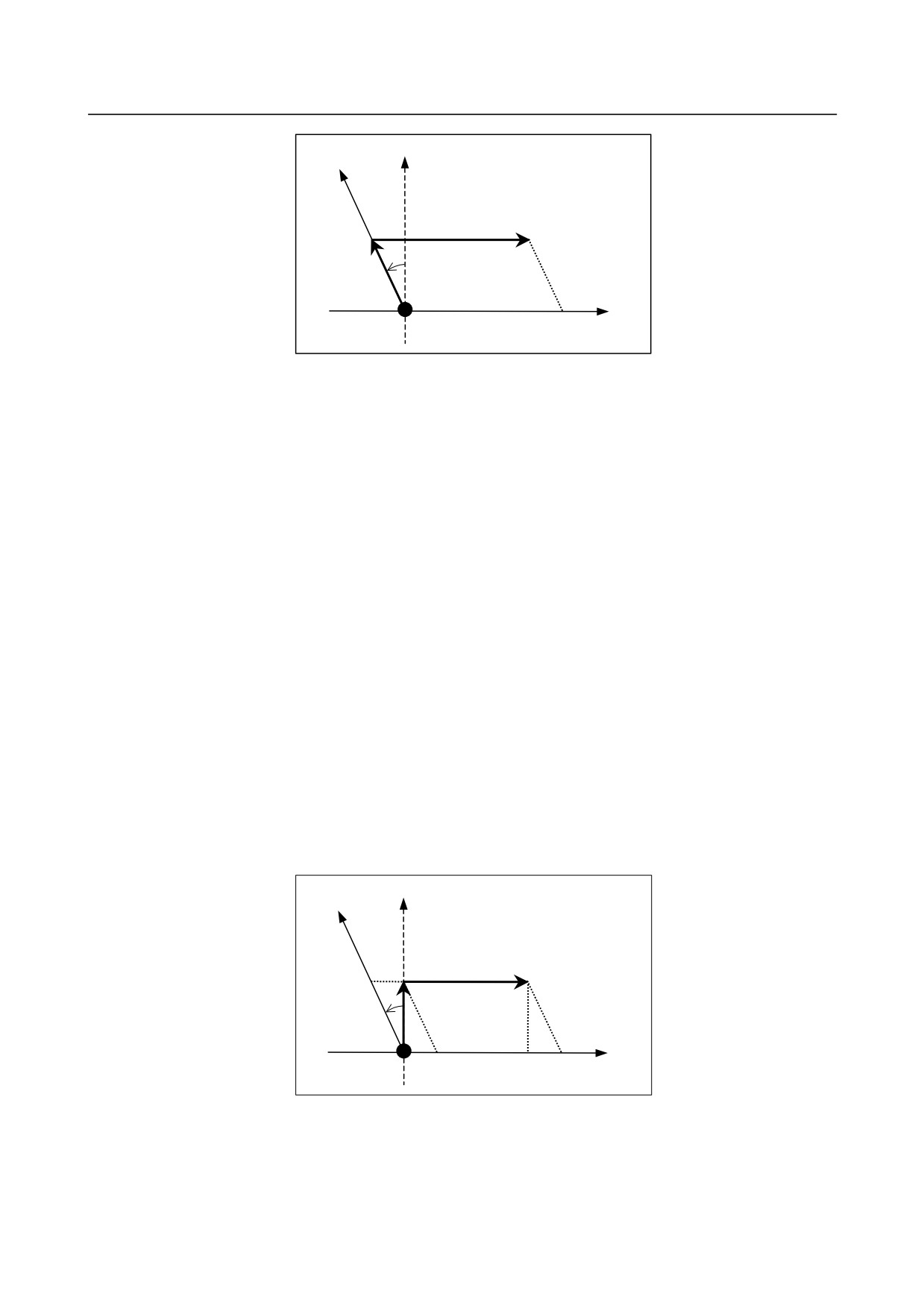
Example)
(when the Y-axis is an angular axis, the X-axis is a perpendicular axis, and the inclination angle is
-30°)
1
Move command for movement from point P0 to point P1
>G90G53Y100.
2
Move command for movement from point P1 to point P2
>G90G53X200.
<1> Coordinates of P1
(Absolute coordinate)
(Machine coordinate)
X
-50.000
X
0.000
Y
86.603
Y
100.000
<2> Coordinates of P2
(Absolute coordinate)
(Machine coordinate)
X
150.000
X
200.000
Y
86.603
Y
100.000
- 281 -
17.AXIS CONTROL FUNCTIONS PROGRAMMING
B-64304EN/02
+Y (Angular axis)
+Y' (Hypothetical axis)
P1(0,100)
P2(200,100)
30°
+X
(Perpendicular
axis)
P0(0,0)
-
Commands for linear interpolation and linear interpolation type positioning
(G01, G00)
The tool moves to a specified position in the Cartesian coordinate system when the following is specified:
(G90)G00X_Y_;
or
(G90)G01X_Y_F_;
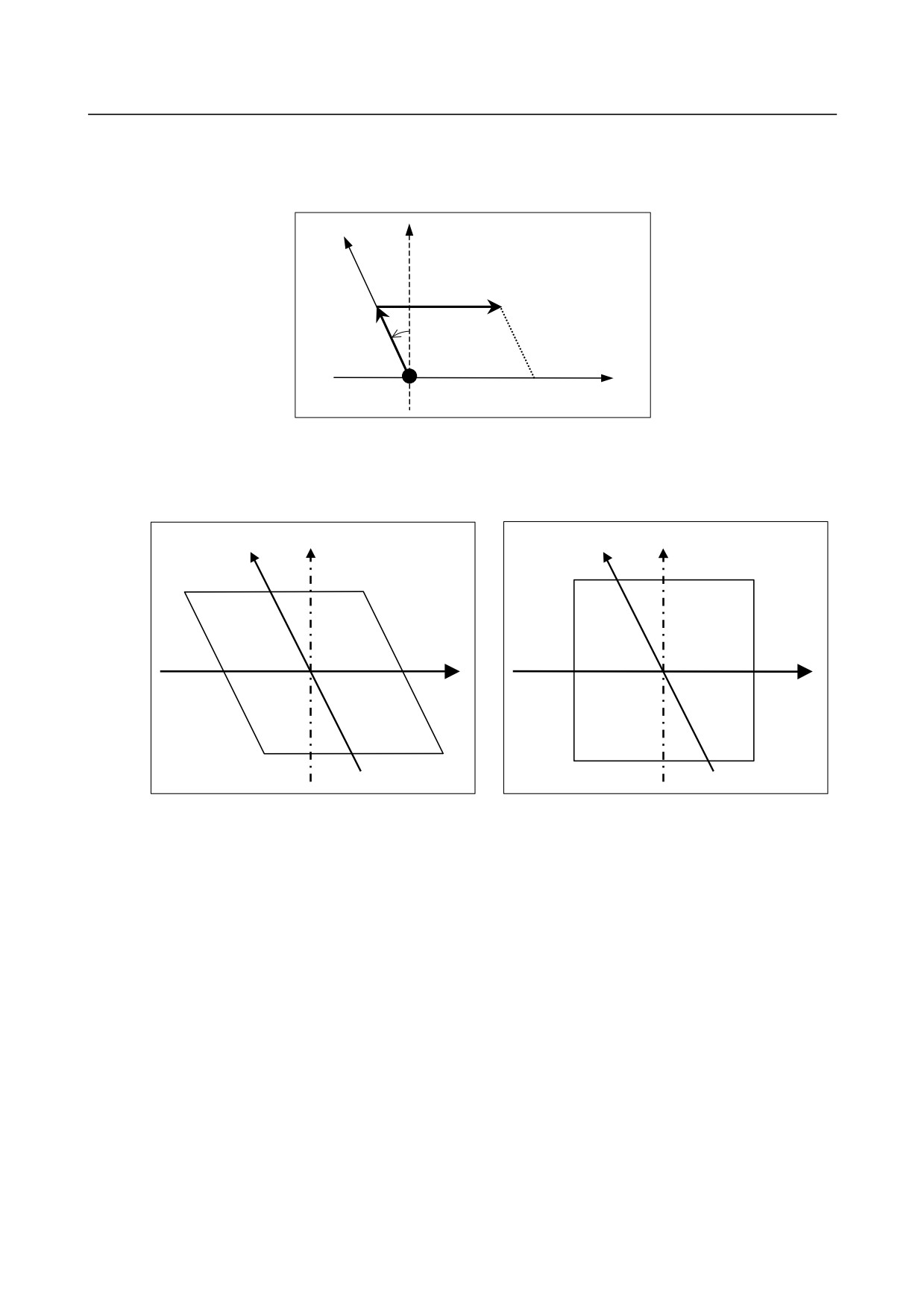
Example)
Examples of positioning
(when the Y-axis is an angular axis, the X-axis is a perpendicular axis, and the inclination angle is
-30°)
1
Move command for movement from point P0 to point P1
> G90 G00 Y100. ;
2
Move command for movement from P1 to P2
> G90 G00 X200. ;
(1) When the perpendicular axis/angular axis control disable signal (NOZAGC) is set to 0
<1> Coordinates of P1
(Absolute coordinate)
(Machine coordinate)
X
0.000
X
57.735
Y
100.000
Y
115.470
<2> Coordinates of P2
(Absolute coordinate)
(Machine coordinate)
X
200.000
X
257.735
Y
100.000
Y
115.470
+Y (Angular axis)
+Y' (Hypothetical axis)
P1
P2
115.470
30°
+X (Perpen-
dicular axis)
P0(0,0)
57.735
200
257.735
(2) When the perpendicular axis/angular axis control disable signal (NOZAGC) is set to 1
<1> Coordinates of P1
(Absolute coordinate)
(Machine coordinate)
X
0.000
X
0.000
Y
100.000
Y
115.470
- 282 -
B-64304EN/02
PROGRAMMING
17.AXIS CONTROL FUNCTIONS
<2> Coordinates of P2
(Absolute coordinate)
(Machine coordinate)
X
200.000
X
200.000
Y
100.000
Y
115.470
+Y (Angular axis)
+Y' (Hypothetical axis)
P2
P1
115.470
30°
+X (Perpendicular
axis)
P0(0,0)
200
-
Stored stroke limit
Stored stroke limits under arbitrary angular axis control can be set not in a angular coordinate system but
in the Cartesian coordinate system by setting bits 2, 1, and 0 (AO3, AO2, and AOT) of parameter No.
8201.
Y'
Y'
Y
Y
X
X
Fig. 17.3 (c) OT area in a angular coordinate system Fig. 17.3 (d) OT area in a Cartesian coordinate system
Machine coordinates include a value converted for the angular axis and a compensation value for the
perpendicular axis, so that a angular machine coordinate system as shown in Fig. 17.3 (c) results.
A stored stroke limit is checked in the machine coordinate system, so that the limit area is slanted to form
a rhombus as shown in Fig. 17.3 (c). In this case, the area cannot be identified intuitively. So, stroke
limits are checked not in an actual angular machine coordinate system but in a virtual Cartesian machine
coordinate system as shown in Fig. 17.3 (d).
The functions that operate in the Cartesian coordinate system are:
• Stored stroke check 1 (Both of I and II)
• Stored stroke check 2 (G22/G23)
• Stored stroke check 3
• Stored stroke check before move
The stored stroke check function before move does not work in a angular coordinate system.
Unless this function is enabled, and the coordinate system is converted to the Cartesian coordinate
system, no stroke check is made.
• Bit 7 (BFA) of parameter No. 1300 for specifying whether to issue an alarm before or after a stroke
limit is exceeded (valid for OT1 and OT3)
- 283 -

17.AXIS CONTROL FUNCTIONS PROGRAMMING
B-64304EN/02
M
• Stroke limit external setting (valid only for OT1)
The stored stroke limit functions other than the above work in a angular coordinate system.
-
Relationships between this function and axis-by-axis input/output signals
The table below indicates the relationships between this function and the meaning of each controlled axis
signal.
The input/output signals are classified as signals valid for the program coordinate system (Cartesian
coordinate system) and signals valid for the machine coordinate system (angular coordinate system). In
the "Classification" column, "Cartesian" is indicated for a signal that is valid for the Cartesian coordinate
system, and "Angular" is indicated for a signal that is valid for the angular coordinate system.
A signal valid for the Cartesian coordinate system means a signal valid for a specified axis, and a signal
valid for the angular coordinate system is a signal valid for actual machine movement.
That is, when the perpendicular axis is moved by a command only for the angular axis:
A signal valid for the Cartesian coordinate system is affected by a movement along the angular axis.
A signal valid for the angular coordinate system is not affected by a movement along the angular
axis.
Input signal
Signal name
Address
Classification
Remarks
When a movement is made along the angular
axis only, interlocking the perpendicular axis
does not interlock a movement along the
perpendicular axis made by a movement along
Interlock for each axis
*ITx
G130
Cartesian
the angular axis.
Caution) When using the interlock signal for
each axis, make both of the angular
axis and perpendicular axis high.
This signal is applied to each axis independently.
*+Lx
G114
(If the perpendicular axis is made high, no alarm
Overtravel
Angular
*-Lx
G116
is issued for the perpendicular axis even when
an OT alarm is issued for the angular axis.)
Deceleration signal for
*DECx
X009
Angular
This signal is applied to each axis independently.
reference position return
Servo-off signal
SVFx
G126
Angular
This signal is applied to each axis independently.
Control axis detach
DTCHx
G124
Angular
This signal is applied to each axis independently.
signal
A movement is made in the Cartesian coordinate
Feed axis direction
+Jx
G100
system.
(When the +J/-J signal for the angular
Cartesian
selection signal
-Jx
G102
axis is made high, a movement is made also
along the perpendicular axis.)
Mirror image is applied to the angular coordinate
system for each axis independently.
Caution) Be sure to turn off the mirror image
Mirror image
MIx
G106
Angular
signal for the angular axis and
perpendicular axis engaged in manual
operation.
Manual feed interlock
signal for each axis
+MIT1,
X004.2,
Set the tool compensation parameter in the
direction, tool
Cartesian
+MIT2
4
Cartesian coordinate system.
compensation value
write signal
Machine lock for each
MLKx
G108
Angular
This signal is applied to each axis independently.
axis
- 284 -

B-64304EN/02
PROGRAMMING
17.AXIS CONTROL FUNCTIONS
Output signal
Signal name
Address
Classification
Remarks
In-position signal
INPx
F104
Angular
Applied to each axis independently.
Mirror image check
MMIx
F108
Angular
Applied to each axis independently.
signal
Controlled axis removal
MDTCHx
F110
Angular
Applied to each axis independently.
in-progress signal
Travel in-progress signal
MVx
F102
Angular
Applied to each axis independently.
Applied to each axis independently. (A manual
reference position return operation and the first
Reference position
ZPx
F094
Cartesian
automatic reference position return operation
return completion signal
after power-up need to be performed first for the
angular axis.)
2nd reference position
ZP2x
F096
Cartesian
Applied to each axis independently.
return completion signal
3rd reference position
ZP3x
F098
Cartesian
Applied to each axis independently.
return completion signal
4th reference position
ZP4x
F100
Cartesian
Applied to each axis independently.
return completion signal
Limitation
-
Linear scale with absolute address reference mark
• For both of the angular axis and perpendicular axis, a linear scale with an absolute address reference
mark must be used.
• Reference position return operation must be first completed along the angular axis.
• Return operation cannot be performed along the perpendicular axis while return operation is being
performed along the angular axis.
T
-
Synchronous control
For synchronous control on axes related to arbitrary angular axis control, the angular axis and Cartesian
axis on the master axis side and the angular axis and Cartesian axis on the slave axis side must be placed
under synchronous control at the same time. Moreover, synchronous control can be exercised between
angular axes only or between Cartesian axes only.
If an attempt is made to perform operation under a condition other than the above, the alarm PS0375 is
issued.
Example)
Path 1
Path 2
X1 (Cartesian axis)
←Synchronous→ X2 (Cartesian axis)
Y1 (angular axis)
←Synchronous→ Y2 (angular axis)
-
Composite control
For composite control on axes related to arbitrary angular axis control, the angular axis and Cartesian axis
on the master axis side and the angular axis and Cartesian axis on the slave axis side must be placed under
composite control at the same time. Moreover, composite control can be exercised between angular axes
only or between Cartesian axes only.
If an attempt is made to perform operation under a condition other than the above, the alarm PS0375 is
issued.
Example)
Path 1
Path 2
X1 (Cartesian axis)
←composite→ X2 (Cartesian axis)
Y1 (angular axis)
←composite→ Y2 (angular axis)
- 285 -
17.AXIS CONTROL FUNCTIONS PROGRAMMING
B-64304EN/02
-
Rigid tapping
As a rigid tapping axis, no angular axis can be used.
-
Functions that cannot be used simultaneously
• Axis synchronous control, rigid tapping, PMC axis control
T
• Polygon turning, superimposed control
M
• Electronic gear box function
CAUTION
1
After arbitrary angular axis control parameter setting, be sure to perform manual
reference position return operation.
2
Before manual reference position return operation is performed along the
perpendicular axis, reference position return operation along the angular axis
must be completed (with the reference position return completion signal for the
angular axis (ZPx) set to 1). If reference position return operation is performed
along the perpendicular axis first, an alarm PS0372 is issued.
3
When the setting is made so that the tool moves along the perpendicular axis
during manual reference position return along the angular axis (bit 2 (AZK) of
parameter No. 8200 is set to 0), if once manual reference position return has
been performed along the angular axis, also perform manual reference position
return along the perpendicular axis immediately after the operation.
4
To move the perpendicular axis and the angular axis independently for each
other during manual operation, set perpendicular/angular axis control disable
signal NOZAGC to 1.
5
Once the tool has been moved along the angular axis when
perpendicular/angular axis control disable signal NOZAGC has been set to 1,
manual reference position return must be performed.
6
The same increment system must be used with the angular axis and
perpendicular axis.
7
Before a perpendicular axis reference position return check can be made,
angular axis reference position return operation must be completed.
8
No rotary axis must be set for the angular axis and perpendicular axis. A rotary
axis may be specified only for a linear axis.
9
Set a position switch operation range (parameter Nos. 6930 to 6965) in a
angular coordinate system.
- 286 -
B-64304EN/02
PROGRAMMING
17.AXIS CONTROL FUNCTIONS
17.4 TANDEM CONTROL
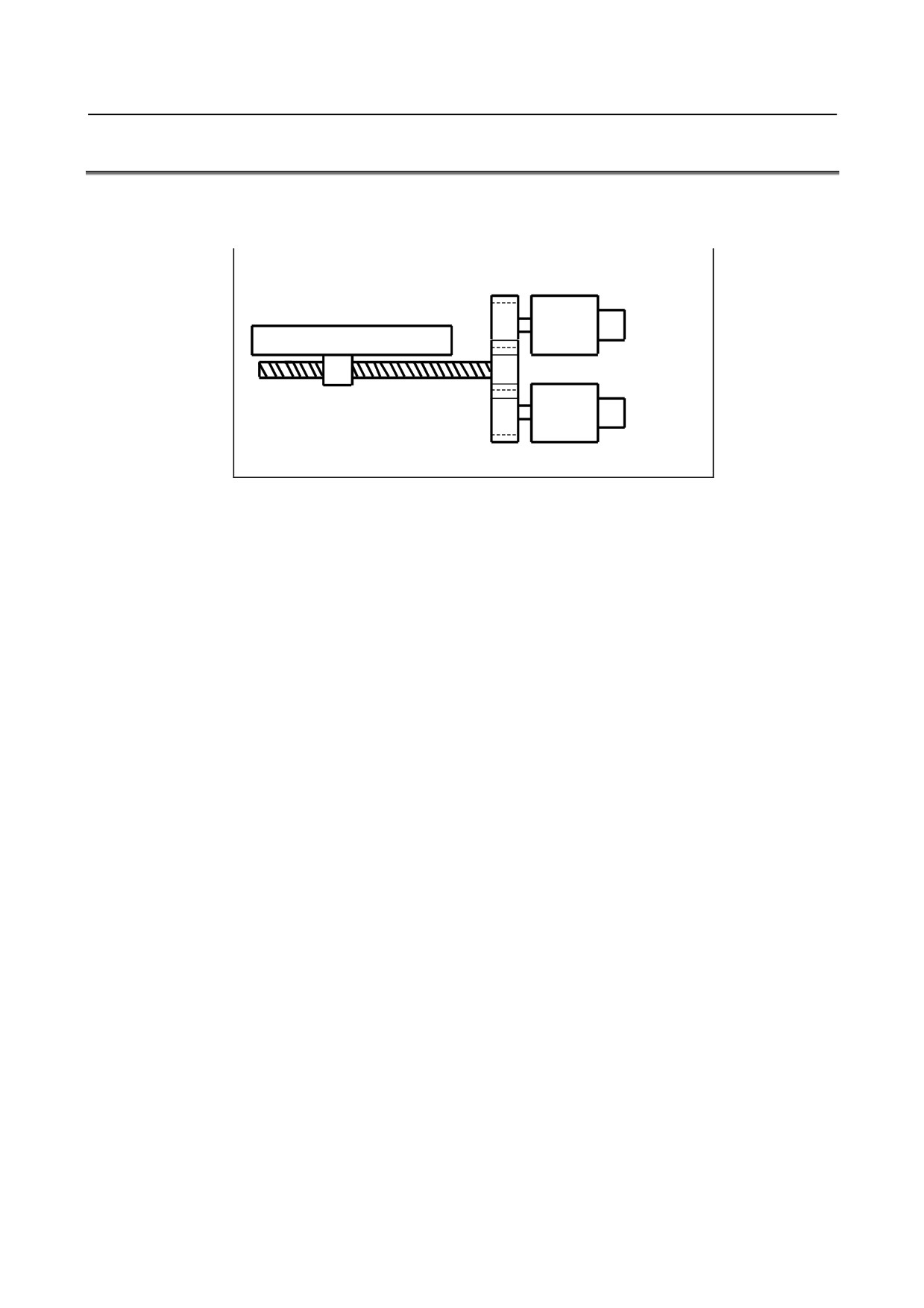
When enough torque for driving a large table cannot be produced by only one motor, two motors can be
used for movement along a single axis. Positioning is performed by the main motor only. The submotor is
used only to produce torque. With this tandem control function, the torque produced can be doubled.
Main motor
Table
Ball screw
Sub motor
Fig. 17.4 (a) Example of operation
In general, the NC regards tandem control as being performed for one axis. However, for servo parameter
management and servo alarm monitoring, tandem control is regarded as being performed for two axes.
For details, refer to the relevant manual published by the machine tool builder.
- 287 -
18.PATTERN DATA INPUT
PROGRAMMING
B-64304EN/02
18 PATTERN DATA INPUT
Chapter 18, "PATTERN DATA INPUT", consists of the following sections:
18.1 OVERVIEW
288
18.2 EXPLANATION
288
18.3 EXPLANATION OF OPERATION
290
18.4 DEFINITION OF THE SCREEN
291
18.1 OVERVIEW
In the program of the fixed form processing with the custom macro, the operator select the processing
pattern on the menu screen and specified the size, number and so on to the variable on the custom macro
screen. As above mentioned, this function enables users to perform programming simply without
programming using an existing NC language.
With the aid of this function, a machine tool builder can prepare the program of a hole machining cycle
(such as a boring cycle or tapping cycle) using the custom macro function, and can store it into the
program memory.
This cycle is assigned pattern names, such as BOR1, TAP3, and DRL2.
An operator can select a pattern from the menu of pattern names displayed on the screen.
Data (pattern data) which is to be specified by the operator should be created in advance with variables in
a drilling cycle.
The operator can identify these variables using names such as DEPTH, RETURN RELIEF, FEED,
MATERIAL or other pattern data names. The operator assigns values (pattern data) to these names.
The operator selects the pattern on the menu screen, and the selected pattern number is assigned to the
system variable. The custom macro of the selected pattern can be started by starting a program then
referring to the system variable in the program.
18.2 EXPLANATION
This function is consist of Pattern menu screen and Custom macro screen.
The process pattern is selected on the pattern menu screen.
Then the process pattern is selected, the custom macro screen is displayed.
On this custom macro screen, the variable with the name and comment is displayed according to the
selected process pattern.
The process data can be input by referring to the variable name with the numerical value on the drawing.
Bit 7 (NPD) of parameter No. 8135 can be set to enable or disable this function (0: enabled, 1: disabled).
When this function is disabled, the above screens are not displayed.
The following is the example for the pattern menu and the custom macro.
- 288 -
B-64304EN/02
PROGRAMMING
18.PATTERN DATA INPUT
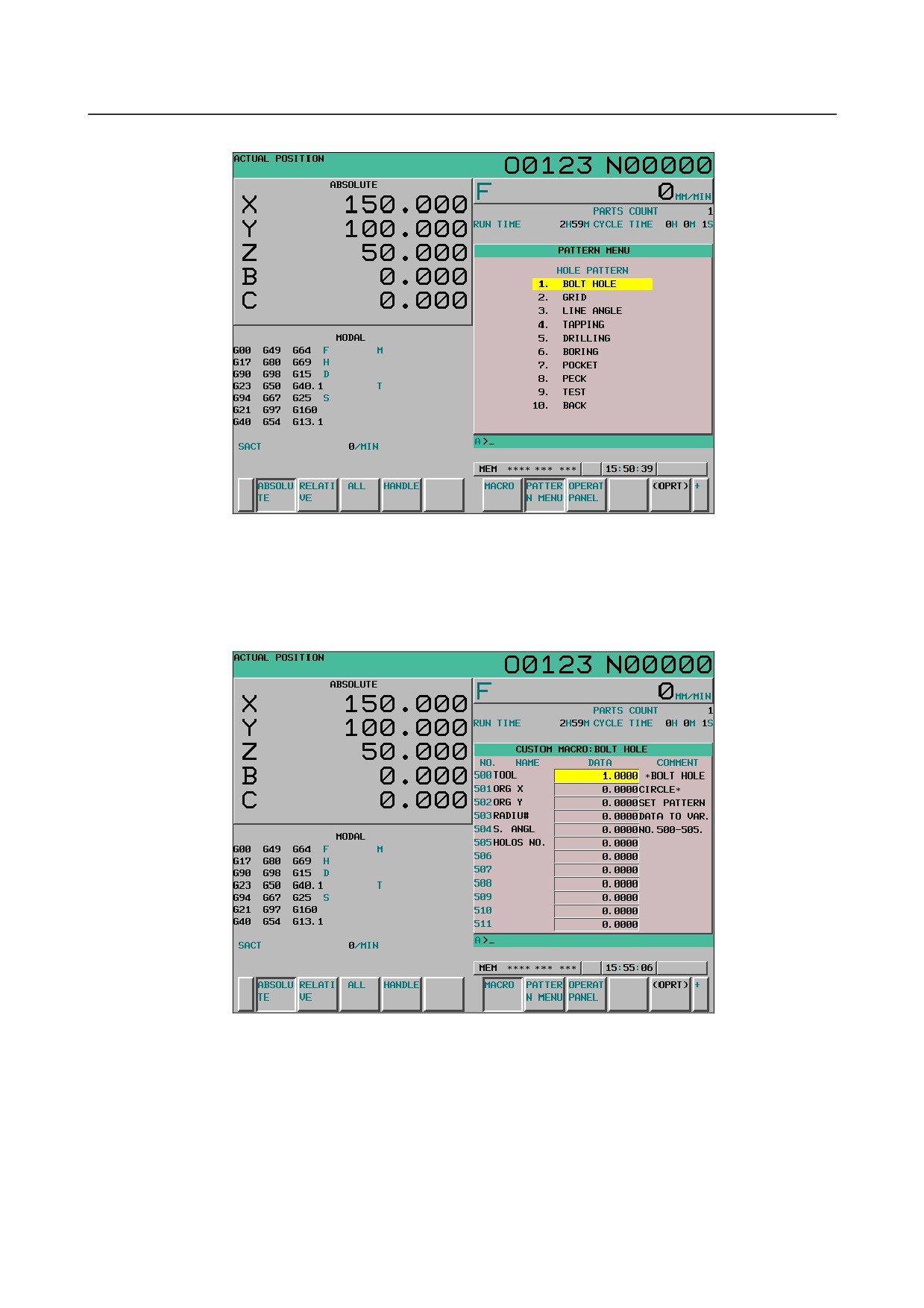
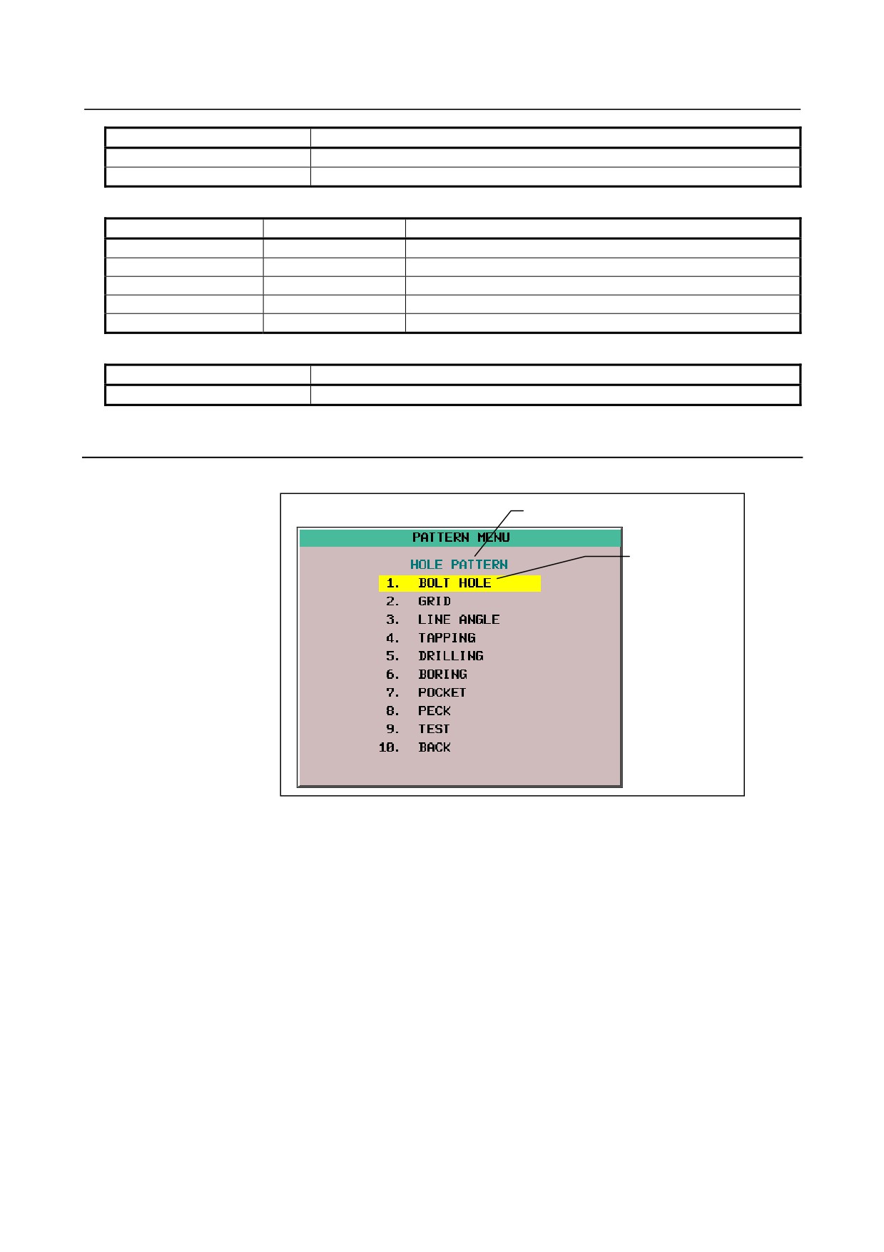
(1) Pattern menu screen
Fig. 18.2 (a) Pattern data menu screen (10.4-inch)
(2) Custom macro screen
The name of variable and comment can be displayed on the usual custom macro screen.
The menu title and pattern name on the pattern menu screen and the variable name on the custom
macro screen can be defined
Fig. 18.2 (b) Custom macro screen (10.4-inch)
- 289 -
18.PATTERN DATA INPUT
PROGRAMMING
B-64304EN/02
18.3 EXPLANATION OF OPERATION
The following explains how to display the pattern menu screen.
1
Press function key
2
Press continuous menu key
3
Press soft key [PATTERN MENU] ([MENU] for the 8.4-inch display unit).
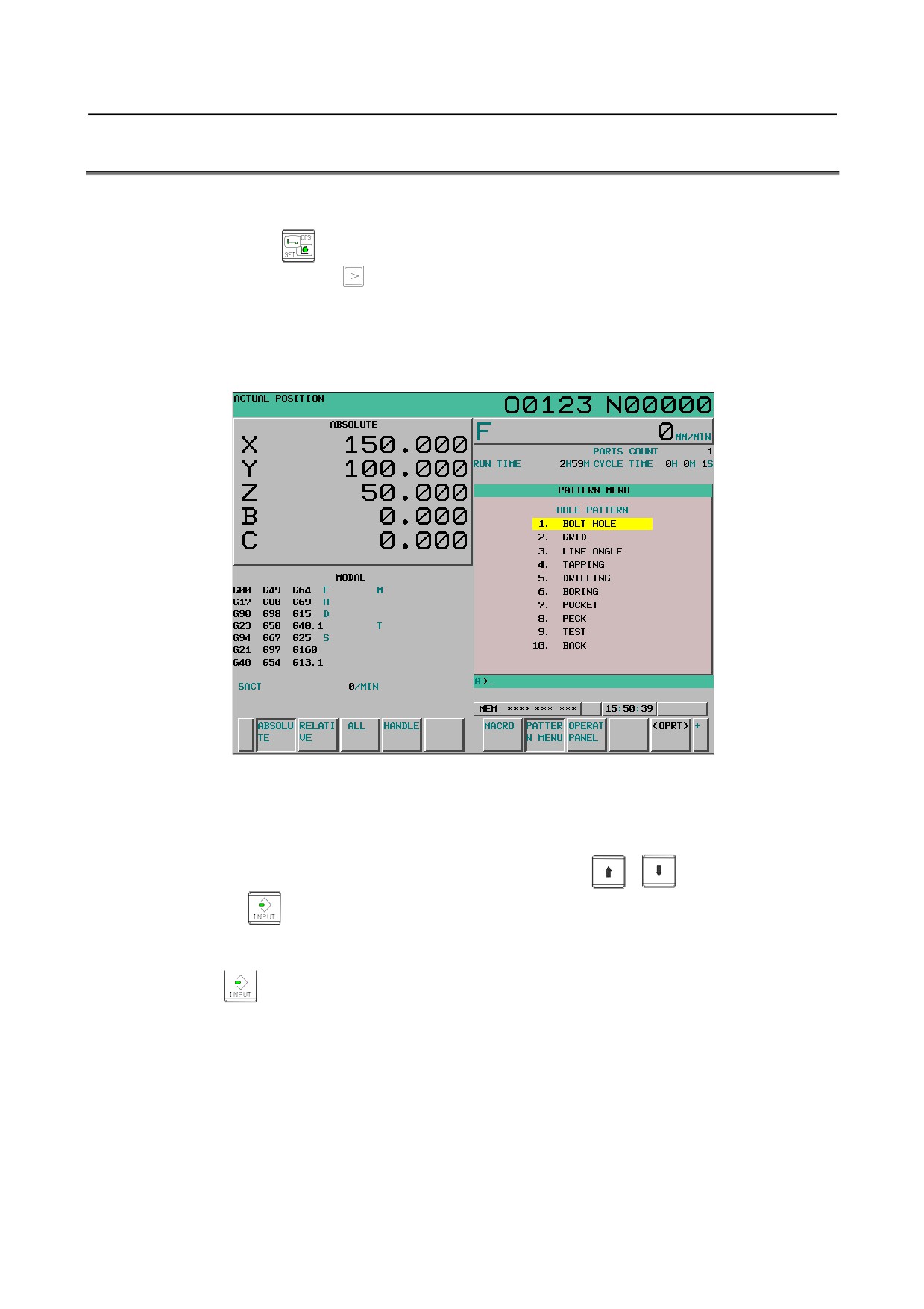
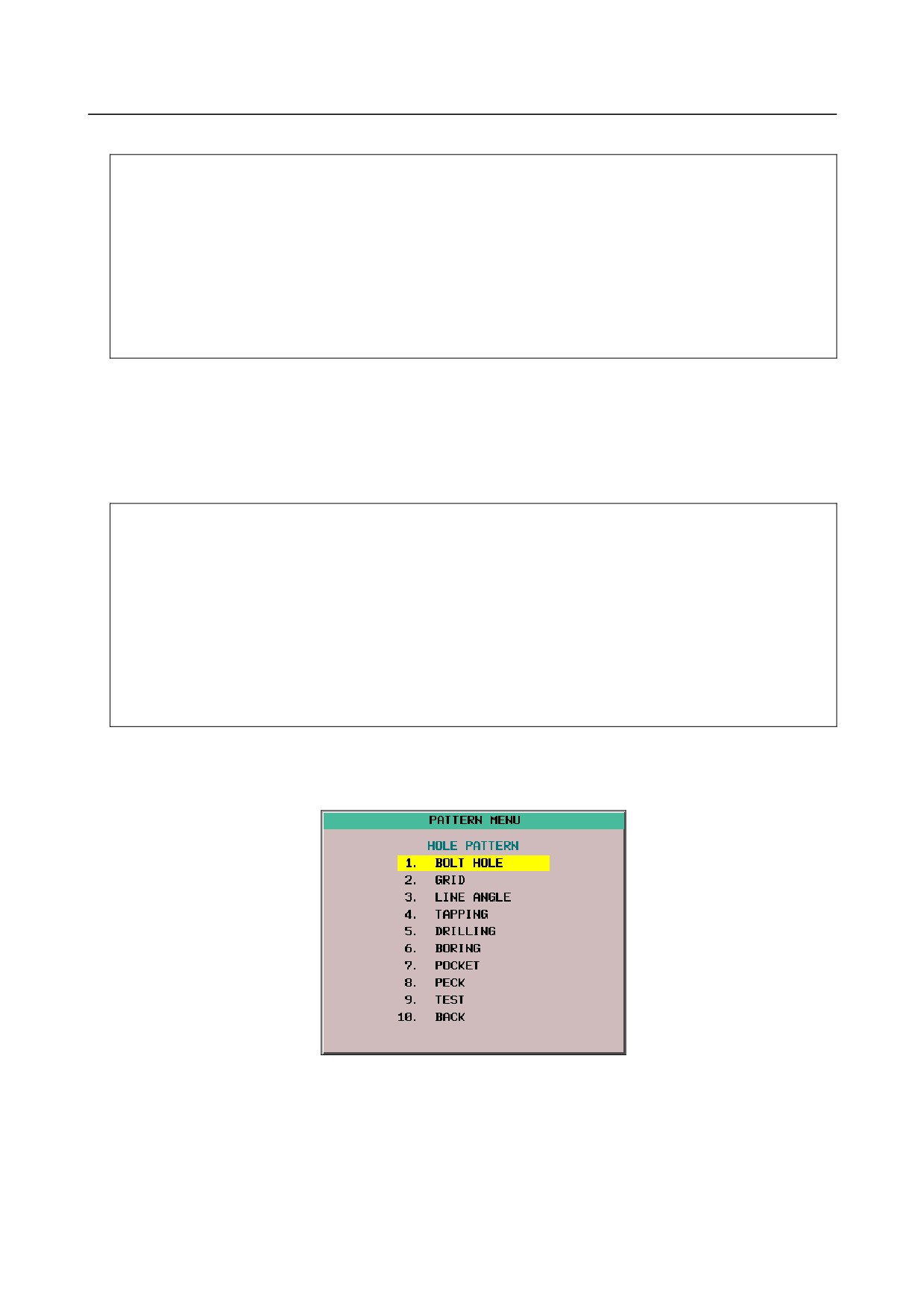
Pattern menu screen
The following pattern menu is displayed.
Fig. 18.3 (a) Pattern menu screen (10.4-inch)
Select the pattern on this screen
The following two methods are effective.
• Selection by cursor
Move the cursor to the pattern name with the cursor move keys
,
and press the soft key
[SELECT] or
key.
• Selection by setting of pattern number
The number that is displayed in the left side of the pattern name is input and press the soft key
[select] or
key.
The selected pattern number is registered to system variable #5900. The custom macro of the selected
pattern can be started by starting a fixed program (external program No. search) with an external signal.
This program refers to the system variable #5900 in the program. This system variable #5900 is kept after
power-off.
- 290 -
B-64304EN/02
PROGRAMMING
18.PATTERN DATA INPUT
Custom macro variable screen
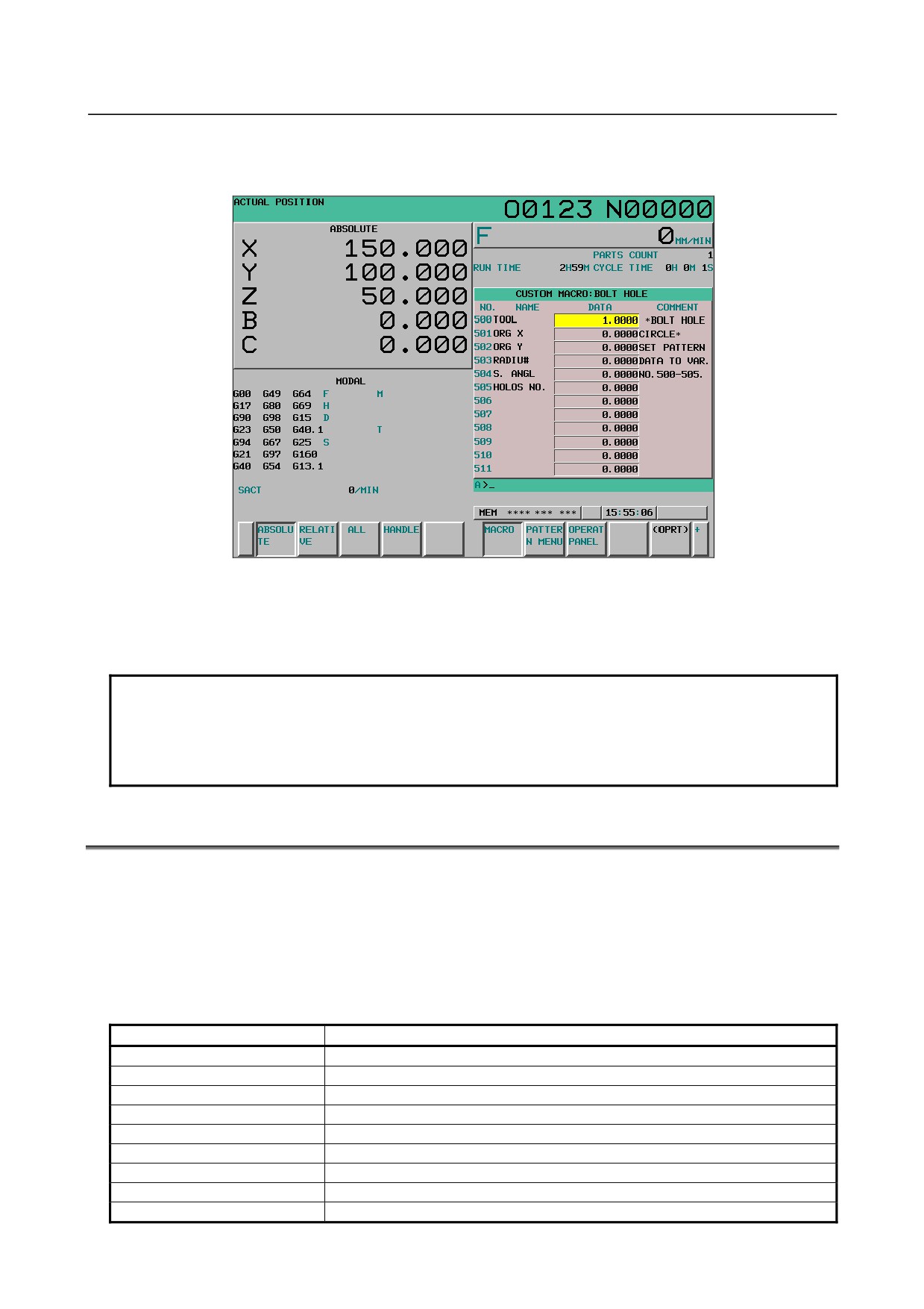
The following custom macro screen is displayed.
Fig. 18.3 (b) Custom macro screen when the pattern data is input (10.4-inch)
When the screen is changed to the custom macro screen, the macro variable number that is selected first is
specified with the parameters Nos.6101 to 6110. The macro variables that variable name is not defined
can be input, too.
NOTE
1 The variable name that is displayed cannot be used as the common variable
name of the NC program.
2 When the common variable name is defined by SETVN command, the variable
name defined by pattern data input function is given priority.
18.4 DEFINITION OF THE SCREEN
The definition of the screen is performed by NC program.
Program configuration
This function is consist of one program for the definition of pattern menu screen and maximum ten
programs for the definition of custom macro screen.
The program number is as follows
Table 18.4 (a) Numbers of subprograms employed in the pattern data input function
Sub program No.
Screen
O9500
Specifies character strings displayed on the pattern data menu.
O9501
Specifies a character string of the pattern data corresponding to pattern No.1
O9502
Specifies a character string of the pattern data corresponding to pattern No.2
O9503
Specifies a character string of the pattern data corresponding to pattern No.3
O9504
Specifies a character string of the pattern data corresponding to pattern No.4
O9505
Specifies a character string of the pattern data corresponding to pattern No.5
O9506
Specifies a character string of the pattern data corresponding to pattern No.6
O9507
Specifies a character string of the pattern data corresponding to pattern No.7
O9508
Specifies a character string of the pattern data corresponding to pattern No.8
- 291 -
18.PATTERN DATA INPUT
PROGRAMMING
B-64304EN/02
Sub program No.
Screen
O9509
Specifies a character string of the pattern data corresponding to pattern No.9
O9510
Specifies a character string of the pattern data corresponding to pattern No.10
Table 18.4 (b) Macro commands used in the pattern data input function
G code
H code
Function
G65
H90
Specifies the menu title.
G65
H91
Specifies the pattern name.
G65
H92
Specifies the pattern data title.
G65
H93
Specifies the variable name.
G65
H94
Specifies the comment.
Table 18.4 (c) System variables employed in the pattern data input function
System variable
Function
#5900
Pattern No. selected by user.
18.4.1 Definition of the Pattern Menu Screen
Menu title and pattern name are defined as follows.
Menu title
Pattern name
Fig. 18.4.1 (a) Pattern menu screen
Definition of menu title
The character string displayed in the menu title of the pattern menu screen is defined.
The menu title is specified up to 12 characters in a half size letter and up to 6 characters in a full size
letter such as kanji character.
- 292 -
B-64304EN/02
PROGRAMMING
18.PATTERN DATA INPUT
-
Format
G65 H90 P_ Q_ R_ I_ J_ K_ ;
H90 : Specifies the menu title
P_
: The code of 1st and 2nd characters of title
Q_
: The code of 3rd and 4th characters of title
R_
: The code of 5th and 6th characters of title
I_
: The code of 7th and 8th characters of title
J_
: The code of 9th and 10th characters of title
K_
: The code of 11th and 12th characters of title
As for the way of setting the character-code, refer to the Subsection 18.4.3, "Setting the
Character-codes" in the Part II, “Programming.”
Definition of pattern name
The character string displayed in the pattern name which becomes a menu item is defined.
The pattern name is specified up to 10 characters in a half size letter and up to 5 characters in a full size
letter.
-
Format
G65 H91 P_ Q_ R_ I_ J_ K_ ;
H91 : Specifies the pattern name
P_
: Specifies the menu number of the pattern name
The menu number = 1 to 10
Q_
: The code of 1st and 2nd characters of pattern name
R_
: The code of 3rd and 4th characters of pattern name
I_
: The code of 5th and 6th characters of pattern name
J_
: The code of 7th and 8th characters of pattern name
K_
: The code of 9thd and 10th characters of pattern name
As for the way of setting the character-code, refer to the Subsection 18.4.3, "Setting the
Character-codes" in the Part II, “Programming.”
Example
The following is example for pattern menu screen.
Fig. 18.4.1 (b) Pattern menu screen
- 293 -
18.PATTERN DATA INPUT
PROGRAMMING
B-64304EN/02
O9500 ;
N1 G65 H90 P072079 Q076069 R032080 I065084 J084069 K082078 ;.. "HOLE PATTERN"
N2 G65 H91 P1 Q066079 R076084 I032072 J079076 K069032 ;
"BOLT HOLE"
N3 G65 H91 P2 Q071082 R073068 ;
"GRID"
N4 G65 H91 P3 Q076073 R078069 I032065 J078071 K076069 ;
"LINE ANGLE"
N5 G65 H91 P4 Q084065 R080080 I073078 J071032 ;
"TAPPING"
N6 G65 H91 P5 Q068082 R073076 I076073 J078071 ;
"DORILLING"
N7 G65 H91 P6 Q066079 R082073 I078071 ;
"BORING"
N8 G65 H91 P7 Q080079 R067075 I069084 ;
"POCKET"
N9 G65 H91 P8 Q080069 R067075 ;
"PECK"
N10 G65 H91 P9 Q084069 R083084 ;
"TEST"
N11 G65 H91 P10 Q066065 R067075 ;
"BACK"
N12 M99 ;
18.4.2 Definition of the Custom Macro Screen
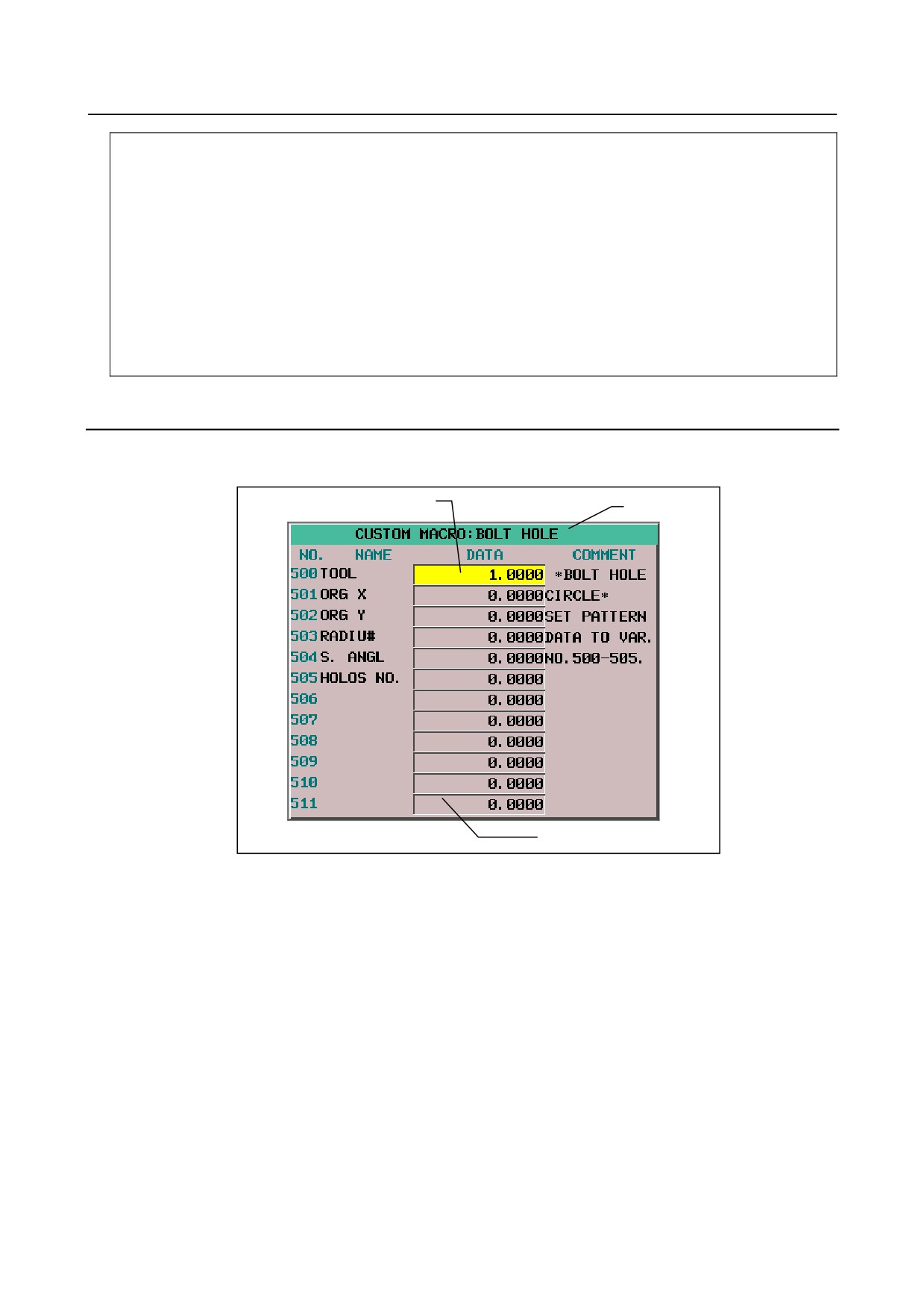
The title, variable name and comment are defined as follows.
Macro variable name
Title
Comment
Fig. 18.4.2 (a) Custom macro screen
Definition of title
The character string displayed in the title of the custom macro screen is defined.
The title is specified up to 12 characters in a half size letter and up to 6 characters in a full size letter.
- 294 -
B-64304EN/02
PROGRAMMING
18.PATTERN DATA INPUT
-
Format
G65 H92 P_ Q_ R_ I_ J_ K_ ;
H92 : Specifies the menu title
P_ : The code of 1st and 2nd characters of the menu title
Q_ : The code of 3rd and 4th characters of the menu title
R_ : The code of 5th and 6th characters of the menu title
I_
: The code of 7th and 8th characters of the menu title
J_
: The code of 9th and 10th characters of the menu title
K_ : The code of 11th and 12th characters of the menu title
As for the way of setting the character-code, refer to the Subsection 18.4.3, "Setting the
Character-codes" in the Part II, “Programming.”
Definition of macro variable
The character string displayed in the macro variable name is defined.
The macro variable is specified up to 10 characters in a half size letter and up to 5 characters in a full size
letter.
The variable which can be used is as follows
#100 to 199 (100 variables)
#500 to 999 (500 variables), 600 variables in total
-
Format
G65 H93 P_ Q_ R_ I_ J_ K_ ;
H93 : Specifies the variable name
P_ : Specifies the variable number
Specifies 100 to 199 or 500 to 999
Q_ : The code of 1st and 2nd characters of the variable name
R_ : The code of 3rd and 4th characters of the variable name
I_
: The code of 5th and 6th characters of the variable name
J_
: The code of 7th and 8th characters of the variable name
K_ : The code of 9th and 10th characters of the variable name
As for the way of setting the character-code, refer to the Subsection 18.4.3, "Setting the
Character-codes" in the Part II, “Programming.”
Definition of a comment
The character string of the comment displayed on the custom macro screen is defined.
The comment is specified by up to 12 characters in a half size letter and up to 6 characters in a full size
letter per one block.
1 line is composed by 1 blocks, the maximum number of lines is 8 on the 8.4-inch display unit or 12 on
the 10.4-inch display unit.
Blocks are displayed from the first comment line in the order specified in the program.
- 295 -
18.PATTERN DATA INPUT
PROGRAMMING
B-64304EN/02
-
Format
G65 H94 P_ Q_ R_ I_ J_ K_ ;
H94 : Specifies the comment
P_ : The code of 1st and 2nd characters of comment
Q_ : The code of 3rd and 4th characters of comment
R_ : The code of 5th and 6th characters of comment
I_
: The code of 7th and 8th characters of comment
J_
: The code of 9th and 10th characters of comment
K_ : The code of 11th and 12th characters of comment
As for the way of setting the character-code, refer to the Subsection 18.4.3, "Setting the
Character-codes" in the Part II, “Programming.”
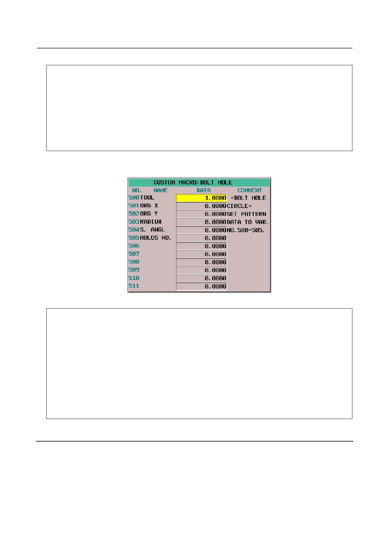
Example
The following is example of the custom macro screen.
Fig. 18.4.2 (c) Custom macro screen
O9501 ;
N1 G65 H92 P066079 Q076084 R032072 I079076 J069032 ;
"BOLT HOLE"
N2 G65 H93 P500 Q084079 R079076 ;
"TOOL"
N3 G65 H93 P501 Q079082 R071032 I08832 ;
"ORG X"
N4 G65 H93 P502 Q079082 R071032 I08932 ;
"ORG Y"
N5 G65 H93 P503 Q082065 R068073 I085803 ;
"RADIUS"
N6 G65 H93 P504 Q083046 R032065 I078071 J076032 ;
"S. ANGL"
N7 G65 H93 P505 Q072079 R076079 I083032 J078079 K046032 ;
"HOLES NO."
N8 G65 H94 P032042 Q066079 R076084 I032072 J079076 K069032 ;
" *BOLT HOLE"
N9 G65 H94 P067073 Q082067 R076069 I042032 ;
"CIRCLE*"
N10 G65 H94 P083069 Q084032 R080065 I084084 J069082 K078032 ;.."SET PATTERN"
N11 G65 H94 P068065 Q084065 R032084 I079032 J086065 K082046 ;.."DATA NO VAR."
N12 G65 H94 P078079 Q046053 R048048 I045053 J048053 K046032 ;.."NO500-505"
N13 M99 ;
18.4.3 Setting the Character-codes
The character cannot be used to specify the NC program.
Therefore, the code corresponding to the character is specified.
One character is consist of three figures in a half size letter and six figures in a full size letter.
The character code is specified for each address of the G65 instruction by six digits.
Refer to the table for the character code.
- 296 -

B-64304EN/02
PROGRAMMING
18.PATTERN DATA INPUT
Example)
When "ABCDEFGH" is specified, the description of the code is as follows.
Encoded character string : 065 066 067 068 069 070 071 072
P065066 Q067068 R069070 I071072 ;
AB
CD EF
GH
NOTE
1 Space (032) is added ahead of the character-code, when the character-code of
three digits or less is specified.
Example)
P065066 Q067 ; → " AB C "
032(space) is put at the end, when "ABC" is displayed.
P065066 Q067032 ; → " ABC "
2 It is assumed in that the space of two characters was defined in the address
when there is an address not defined.
Example)
P065066 I067068 ; → "AB
CD"
Characters and codes to be used for the pattern data input function
Character
Code
Comment
Character
Code
Comment
A
065
6
054
B
066
7
055
C
067
8
056
D
068
9
057
E
069
032
Space
F
070
!
033
Exclamation mark
G
071
”
034
Quotation mark
H
072
#
035
Hash sign
I
073
$
036
Dollar sign
J
074
%
037
Percent
K
075
&
038
Ampersand
L
076
’
039
Apostrophe
M
077
042
Asterisk
N
078
+
043
Plus sign
O
079
,
044
Comma
P
080
-
045
Minus sign
Q
081
046
Period
R
082
/
047
Slash
S
083
:
058
Colon
T
084
;
059
Semicolon
U
085
<
060
Left angle bracket
V
086
=
061
Equal sign
W
087
>
062
Right angle bracket
X
088
?
063
Question mark
Y
089
@
064
At mark
Z
090
[
091
Left square bracket
0
048
¥
092
Yen sign
1
049
]
093
Right square bracket
2
050
^
094
3
051
_
095
Underscore
4
052
5
053
- 297 -

18.PATTERN DATA INPUT
PROGRAMMING
B-64304EN/02
The characters and the codes of the katakana is as follows.
Character
Code
Comment
Character
Code
Comment
ア
177
ム
209
イ
178
メ
210
ウ
179
モ
211
エ
180
ヤ
212
オ
181
ユ
213
カ
182
ヨ
214
キ
183
ラ
215
ク
184
リ
216
ケ
185
ル
217
コ
186
レ
218
サ
187
ロ
219
シ
188
ワ
220
ス
189
ヲ
166
セ
190
ン
221
ソ
191
ァ
167
タ
192
ィ
168
チ
193
ゥ
169
ツ
194
ェ
170
テ
195
ォ
171
ト
196
ャ
172
ナ
197
ュ
173
ニ
198
ョ
174
ヌ
199
ッ
175
ネ
200
″
222
Diacritical mark
ノ
201
°
223
Diacritical mark
ハ
202
。
161
Punctuation
ヒ
203
「
162
Left quotation mark
フ
204
」
163
Right quotation mark
ヘ
205
、
164
Comma
ホ
206
・
165
Point
マ
207
000
Space
ミ
208
NOTE
Diacritical mark is one character.
The characters and the codes of the hiragana and the kanji are as follows. The following hiraganas and
kanjis use two characters of the alphanumeric character.
ぁ
あ
ぃ
い
う
う
ぇ
え
ぉ
お
002 000
002 002
002 004
002 006
002 008
002 010
002 012
002 014
002 016
002 018
か
が
き
ぎ
く
ぐ
け
げ
こ
ご
002 020
002 022
002 024
002 026
002 028
002 030
002 032
002 034
002 036
002 038
さ
ざ
し
じ
す
ず
せ
ぜ
そ
ぞ
002 040
002 042
002 044
002 046
002 048
002 050
002 052
002 054
002 056
002 058
た
だ
ち
ぢ
っ
つ
づ
て
で
と
002 060
002 062
002 064
002 066
002 068
002 070
002 072
002 074
002 076
002 078
ど
な
に
ぬ
ね
の
は
ば
ぱ
ひ
002 080
002 082
002 084
002 086
002 088
002 090
002 092
002 094
002 096
002 098
び
ぴ
ふ
ぶ
ぷ
へ
べ
ぺ
ほ
ぼ
002 100
002 102
002 104
002 106
002 108
002 110
002 112
002 114
002 116
002 118
- 298 -

B-64304EN/02
PROGRAMMING
18.PATTERN DATA INPUT
ぽ
ま
み
む
め
も
ゃ
や
ゅ
ゆ
002 120
002 122
002 124
002 126
002 128
002 130
002 132
002 134
002 136
002 138
ょ
よ
ら
り
る
れ
ろ
わ
わ
素
002 140
002 142
002 144
002 146
002 148
002 150
002 152
002 154
002 156
002 158
材
を
ん
種
類
棒
穴
成
形
質
002 160
002 162
002 164
002 166
002 168
002 170
002 172
002 174
002 176
002 178
寸
法
外
径
長
端
面
最
小
内
002 180
002 182
002 184
002 186
002 188
002 190
002 192
002 194
002 196
002 198
大
加
工
切
削
倣
正
途
中
荒
002 200
002 202
002 204
002 206
002 208
002 210
002 212
002 214
002 216
002 218
具
番
号
仕
上
込
点
方
向
速
002 220
002 222
002 224
002 226
002 228
002 230
002 232
002 234
002 236
002 238
度
送
量
開
始
深
主
軸
002 240
002 242
002 244
002 246
002 248
002 250
002 252
002 254
回
転
数
位
置
決
直
線
時
円
003 000
003 002
003 004
003 006
003 008
003 010
003 012
003 014
003 016
003 018
反
現
在
指
令
値
領
域
診
断
003 020
003 022
003 024
003 026
003 028
003 030
003 032
003 034
003 036
003 038
操
作
手
引
機
械
残
移
動
次
003 040
003 042
003 044
003 046
003 048
003 050
003 052
003 054
003 056
003 058
早
電
源
投
入
間
分
秒
自
運
003 060
003 062
003 064
003 066
003 068
003 070
003 072
003 074
003 076
003 078
負
荷
実
使
用
寿
命
新
規
除
003 080
003 082
003 084
003 086
003 088
003 090
003 092
003 094
003 096
003 098
隅
取
単
補
能
独
終
了
記
角
003 100
003 102
003 104
003 106
003 108
003 110
003 112
003 114
003 116
003 118
溝
刃
幅
広
設
定
一
覧
表
部
003 120
003 122
003 124
003 126
003 128
003 130
003 132
003 134
003 136
003 138
炭
合
金
鋼
超
硬
先
付
摩
耗
003 140
003 142
003 144
003 146
003 148
003 150
003 152
003 154
003 156
003 158
仮
想
副
行
挿
消
去
山
高
準
003 160
003 162
003 164
003 166
003 168
003 170
003 172
003 174
003 176
003 178
備
完
後
弧
助
択
無
視
器
原
003 180
003 182
003 184
003 186
003 188
003 190
003 192
003 194
003 196
003 198
登
録
再
処
理
描
画
過
容
編
003 200
003 202
003 204
003 206
003 208
003 210
003 212
003 214
003 216
003 218
集
未
対
相
座
標
示
名
歯
変
003 220
003 222
003 224
003 226
003 228
003 230
003 232
003 234
003 236
003 238
呼
推
馬
力
系
選
達
閉
003 240
003 242
003 244
003 246
003 248
003 250
003 252
003 254
禁
復
帰
書
個
桁
稼
由
両
半
004 000
004 002
004 004
004 006
004 008
004 010
004 012
004 014
004 016
004 018
逃
底
逆
下
空
四
触
平
代
辺
004 020
004 022
004 024
004 026
004 028
004 030
004 032
004 034
004 036
004 038
格
子
周
心
本
群
停
止
巾
微
004 040
004 042
004 044
004 046
004 048
004 050
004 052
004 054
004 056
004 058
状
路
範
囲
倍
率
注
側
特
殊
004 060
004 062
004 064
004 066
004 068
004 070
004 072
004 074
004 076
004 078
距
離
連
続
増
隔
件
初
期
条
004 080
004 082
004 084
004 086
004 088
004 090
004 092
004 094
004 096
004 098
経
握
圧
扱
陰
隠
右
押
横
黄
004 100
004 102
004 104
004 106
004 108
004 110
004 112
004 114
004 116
004 118
- 299 -

18.PATTERN DATA INPUT
PROGRAMMING
B-64304EN/02
億
屋
化
何
絵
階
概
該
巻
換
004 120
004 122
004 124
004 126
004 128
004 130
004 132
004 134
004 136
004 138
気
起
軌
技
疑
供
共
境
強
教
004 140
004 142
004 144
004 146
004 148
004 150
004 152
004 154
004 156
004 158
掘
繰
係
傾
型
検
権
研
肩
見
004 160
004 162
004 164
004 166
004 168
004 170
004 172
004 174
004 176
004 178
験
元
弦
減
孔
巧
控
更
校
構
004 180
004 182
004 184
004 186
004 188
004 190
004 192
004 194
004 196
004 198
根
左
差
雑
参
散
産
算
治
耳
004 200
004 202
004 204
004 206
004 208
004 210
004 212
004 214
004 216
004 218
式
失
修
十
従
勝
商
少
尚
昇
004 220
004 222
004 224
004 226
004 228
004 230
004 232
004 234
004 236
004 238
植
色
食
伸
信
侵
振
浸
004 240
004 242
004 244
004 246
004 248
004 250
004 252
004 254
真
暗
以
意
異
影
鋭
越
価
可
005 000
005 002
005 004
005 006
005 008
005 010
005 012
005 014
005 016
005 018
科
果
箇
課
各
拡
核
学
掛
漢
005 020
005 022
005 024
005 026
005 028
005 030
005 032
005 034
005 036
005 038
簡
観
関
含
却
客
休
急
業
曲
005 040
005 042
005 044
005 046
005 048
005 050
005 052
005 054
005 056
005 058
均
筋
継
計
軽
言
限
互
降
採
005 060
005 062
005 064
005 066
005 068
005 070
005 072
005 074
005 076
005 078
済
細
姿
思
写
射
斜
者
車
借
005 080
005 082
005 084
005 086
005 088
005 090
005 092
005 094
005 096
005 098
縦
重
出
述
術
渉
照
省
章
証
005 100
005 102
005 104
005 106
005 108
005 110
005 112
005 114
005 116
005 118
象
身
進
人
図
違
印
沿
遠
央
005 120
005 122
005 124
005 126
005 128
005 130
005 132
005 134
005 136
005 138
奥
往
応
会
解
改
割
活
願
基
005 140
005 142
005 144
005 146
005 148
005 150
005 152
005 154
005 156
005 158
奇
寄
岐
既
近
区
矩
駆
偶
旧
005 160
005 162
005 164
005 166
005 168
005 170
005 172
005 174
005 176
005 178
求
球
究
級
欠
結
口
語
誤
交
005 180
005 182
005 184
005 186
005 188
005 190
005 192
005 194
005 196
005 198
厚
項
刻
告
黒
財
策
糸
試
資
005 200
005 202
005 204
005 206
005 208
005 210
005 212
005 214
005 216
005 218
事
持
似
釈
弱
受
収
純
順
所
005 220
005 222
005 224
005 226
005 228
005 230
005 232
005 234
005 236
005 238
序
剰
場
常
飾
水
錐
据
005 240
005 242
005 244
005 246
005 248
005 250
005 252
005 254
制
整
製
前
全
然
則
属
即
他
006 000
006 002
006 004
006 006
006 008
006 010
006 012
006 014
006 016
006 018
多
存
谷
探
短
徴
鎮
調
頂
鉄
006 020
006 022
006 024
006 026
006 028
006 030
006 032
006 034
006 036
006 038
添
頭
同
導
道
熱
年
濃
箱
発
006 040
006 042
006 044
006 046
006 048
006 050
006 052
006 054
006 056
006 058
抜
伴
必
百
複
物
文
聞
併
忘
006 060
006 062
006 064
006 066
006 068
006 070
006 072
006 074
006 076
006 078
末
密
有
余
与
裏
立
略
青
席
006 080
006 082
006 084
006 086
006 088
006 090
006 092
006 094
006 096
006 098
石
積
赤
接
折
粗
創
双
捜
太
006 100
006 102
006 104
006 106
006 108
006 110
006 112
006 114
006 116
006 118
- 300 -
B-64304EN/02
PROGRAMMING
18.PATTERN DATA INPUT
打
体
待
態
替
段
知
地
致
遅
006 120
006 122
006 124
006 126
006 128
006 130
006 132
006 134
006 136
006 138
追
通
伝
得
読
凸
凹
突
鈍
敗
006 140
006 142
006 144
006 146
006 148
006 150
006 152
006 154
006 156
006 158
杯
背
配
品
不
布
並
頁
別
片
006 160
006 162
006 164
006 166
006 168
006 170
006 172
006 174
006 176
006 178
返
勉
弁
保
明
滅
木
目
歪
揺
006 180
006 182
006 184
006 186
006 188
006 190
006 192
006 194
006 196
006 198
様
溶
要
抑
良
輪
和
話
枠
節
006 200
006 202
006 204
006 206
006 208
006 210
006 212
006 214
006 216
006 218
説
絶
千
専
浅
旋
総
走
退
台
006 220
006 222
006 224
006 226
006 228
006 230
006 232
006 234
006 236
006 238
第
題
卓
室
着
柱
鋳
丁
006 240
006 242
006 244
006 246
006 248
006 250
006 252
006 254
低
訂
肉
日
白
薄
比
皮
被
非
007 000
007 002
007 004
007 006
007 008
007 010
007 012
007 014
007 016
007 018
美
普
伏
歩
包
門
問
絡
列
万
007 020
007 022
007 024
007 026
007 028
007 030
007 032
007 034
007 036
007 038
利
訳
礼
乱
放
枚
約
練
油
劣
007 040
007 042
007 044
007 046
007 048
007 050
007 052
007 054
007 056
007 058
例
郭
戻
冷
垂
緑
紫
許
測
精
007 060
007 062
007 064
007 066
007 068
007 070
007 072
007 074
007 076
007 078
効
→
↑
←
↓
007 080
007 082
007 084
007 086
007 088
007 090
007 092
007 094
007 096
007 098
板
予
〃
家
装
管
007 100
007 102
007 104
007 106
007 108
007 110
007 112
007 114
007 116
007 118
粉
等
貫
安
α
β
007 120
007 122
007 124
007 126
007 128
007 130
007 132
007 134
007 136
007 138
程
抗
張
任
破
損
御
足
守
般
007 140
007 142
007 144
007 146
007 148
007 150
007 152
007 154
007 156
007 158
納
義
丸
汎
固
毎
当
的
詳
鳥
007 160
007 162
007 164
007 166
007 168
007 170
007 172
007 174
007 176
007 178
適
論
額
縁
温
給
界
混
監
締
007 180
007 182
007 184
007 186
007 188
007 190
007 192
007 194
007 196
007 198
護
己
称
樹
脂
料
落
確
認
報
007 200
007 202
007 204
007 206
007 208
007 210
007 212
007 214
007 216
007 218
排
性
生
績
判
搬
砥
θ
島
壁
007 220
007 222
007 224
007 226
007 228
007 230
007 232
007 234
007 236
007 238
]
[
■
007 240
007 242
007 244
007 246
007 248
007 250
007 252
007 254
- 301 -
III. OPERATION
B-64304EN/02
OPERATION
1.GENERAL
1 GENERAL
Chapter 1, "GENERAL", consists of the following sections:
1.1 MANUAL OPERATION
305
1.2 TOOL MOVEMENT BY PROGRAMING - AUTOMATIC OPERATION
306
1.3 AUTOMATIC OPERATION
307
1.4 TESTING A PROGRAM
308
1.5 EDITING A PROGRAM
310
1.6 DISPLAYING AND SETTING DATA
310
1.7 DISPLAY
313
1.1
MANUAL OPERATION
Explanation
-
Manual reference position return
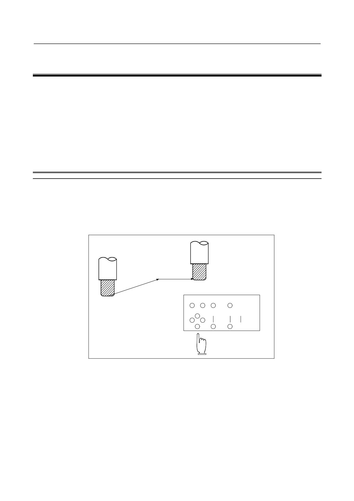
The CNC machine tool has a position used to determine the machine position.
This position is called the reference position, where the tool is replaced or the coordinate are set.
Ordinarily, after the power is turned on, the tool is moved to the reference position.
Manual reference position return is to move the tool to the reference position using switches and
pushbuttons located on the operator's panel. (See Section III-3.1)
Reference position
Tool
Machine operator's panel
Fig. 1.1 (a) Manual reference position return
The tool can be moved to the reference position also with program commands.
This operation is called automatic reference position return (See Section II-6.1).
-
The tool movement by manual operation
Using machine operator's panel switches, pushbuttons, or the manual handle, the tool can be moved along
each axis.
- 305 -