FANUC Series 0i-MODEL D, Series 0i Mate-MODEL D. OPERATOR'S MANUAL - page 10
16. HIGH-SPEED CUTTING
FUNCTIONS
PROGRAMMING
B-64304EN/02
* Look-ahead bell-shaped acceleration/deceleration before interpolation is an optional function.
-
Setting an acceleration
T
A permissible acceleration for the linear acceleration/deceleration of each axis is set in parameter No.
1660. The acceleration/deceleration is performed with the maximum tangential acceleration not
exceeding the permissible acceleration of each axis specified in parameter No. 1660.
M
A permissible acceleration for the linear acceleration/deceleration of each axis is set in parameter No.
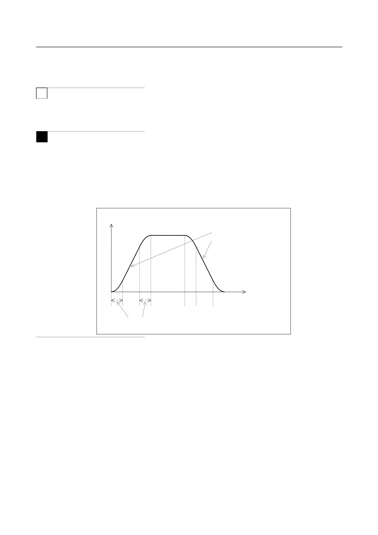
1660. For bell-shaped acceleration/deceleration, acceleration change time (B) (period of transition from
constant speed state (A) to constant acceleration/ deceleration state (C)) is set in parameter No. 1772. In
the constant acceleration/deceleration state (C), acceleration/deceleration is performed with the maximum
tangential acceleration not exceeding the permissible acceleration of each axis specified in parameter No.
1660.
The acceleration change time specified in parameter No.
1772 is held constant, regardless of the
tangential acceleration.
Tangential feedrate
An optimum gradient is
automatically calculated from the
setting made in parameter No.
1660.
(A)
(B)
(C)
(B)
(A)
(B)
(C)
(B)
(A)
Time set in parameter 1772
-
Method of determining the tangent acceleration
Acceleration/deceleration is performed with the largest tangent acceleration/deceleration that does not
exceed the permissible acceleration set for each axis.
(Example)
X-axis permissible acceleration:
1000 mm/sec2
Y-axis permissible acceleration:
1200 mm/sec2
Acceleration change time:
20 msec
Program:
N1 G01 G91 X20. F6000 ; (Move on the X-axis.)
G04 X0.01 ;
N2 Y20. ; (Move on the Y-axis.)
G04 X0.01 ;
N3 X20. Y20. ; (Move in the XY direction (at 45 degrees).)
- 246 -
16.HIGH-SPEED CUTTING
B-64304EN/02
PROGRAMMING
FUNCTIONS
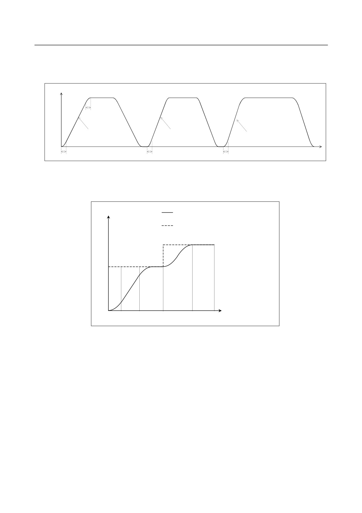
Since N3 performs interpolation for the X and Y axes in the 45-degree direction, the acceleration of the Y
axis is controlled according to the X axis to become 1000 mm/s2. Therefore, the combined acceleration
is 1414 mm/s2.
Tangent feedrate
20ms
1000mm/sec2
1200mm/sec2
1414mm/sec2
gradient
gradient
gradient
20ms
20ms
20ms
-
Acceleration
Acceleration is performed so that the feedrate programmed for a block is attained at the beginning of the
block. When look-ahead acceleration/deceleration before interpolation is valid for multiple blocks,
acceleration can be performed across more than one block.
Feedrate
Speed control by look-ahead
acceleration/deceleration before interpolation
Programmed speed
Time
N1 N2
N3
N4
N5
- 247 -
16. HIGH-SPEED CUTTING
FUNCTIONS
PROGRAMMING
B-64304EN/02
-
Deceleration
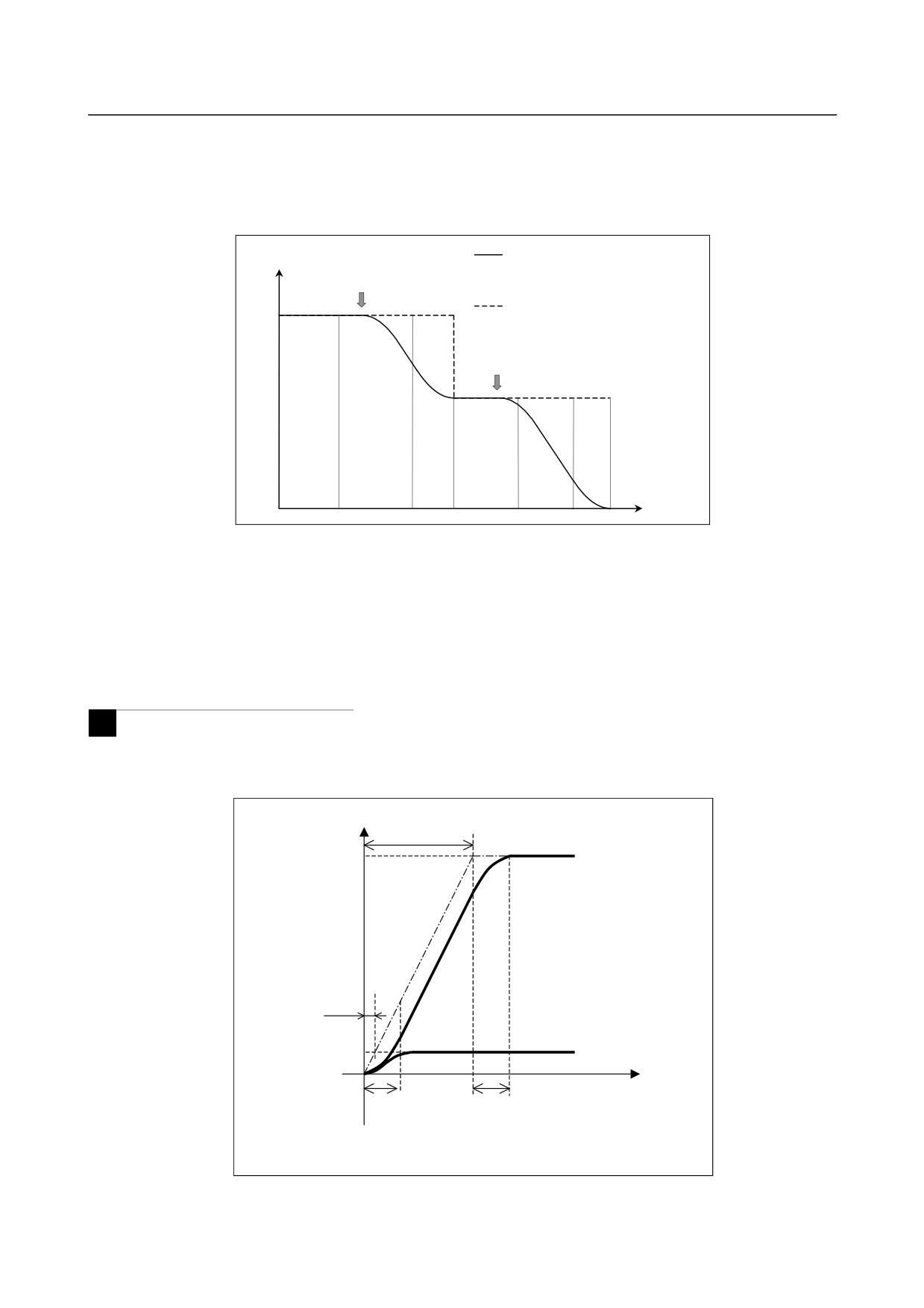
Deceleration starts in advance so that the feedrate programmed for a block is attained at the beginning of
the block.
When look-ahead acceleration/deceleration before interpolation is valid for multiple blocks, deceleration
can be performed across more than one block.
Feedrate
Speed control by look-ahead
Deceleration
acceleration/deceleration before
start point
interpolation
Programmed speed
Deceleration
start point
Time
-
Deceleration based on a distance
If the total distance of the blocks read ahead becomes shorter than or equal to the deceleration distance
obtained from the current feedrate, deceleration starts.
If the total distance of the blocks read ahead during deceleration increases, acceleration is performed.
If the blocks of a small amount of travel are successively specified, deceleration and acceleration may be
performed alternately, making the feedrate inconsistent.
To avoid this, decrease the programmed feedrate.
M
-
Function for changing time constant of bell-shaped acceleration/deceleration
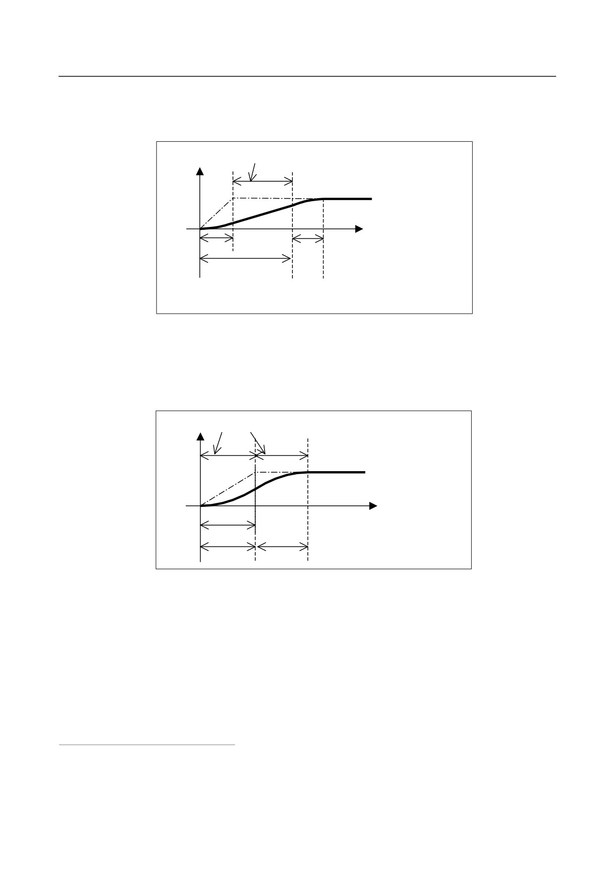
Bell-shaped acceleration/deceleration before interpolation is performed according to the acceleration and
acceleration change time set by the parameters, as shown in the figure below.
Feedrate
T1
Specified
feedrate
T1low
Low specified
feedrate
Time
T2
T2
T1 : Time obtained from specified feedrate and specified acceleration
(specified feedrate/acceleration (parameter No. 1660))
T2 : Acceleration change time
(parameter No. 1772)
- 248 -
16.HIGH-SPEED CUTTING
B-64304EN/02
PROGRAMMING
FUNCTIONS
Here, the acceleration change time (T2) remains constant regardless of the specified feedrate, while the
acceleration time for the linear section
(T1), which is determined by acceleration, varies with the
specified feedrate. If T1 becomes shorter than T2 when the specified feedrate is low, linear
acceleration/deceleration not achieving the specified acceleration results, as shown in the figure below.
Linear acceleration/deceleration not achieving
specified acceleration/deceleration
Feedrate
Specified
feedrate
Time
T1low
T1low
T2
T1 : Time obtained from specified feedrate and specified acceleration (specified
feedrate/acceleration (parameter No. 1660))
T2 : Acceleration change time
(parameter No. 1772)
In such a case, set bit 3 (BCG) of parameter No. 7055 to 1. Then, the internal acceleration and vector
time constant of acceleration/ deceleration before interpolation are changed to make the
acceleration/deceleration pattern as close as possible to the optimum bell-shaped acceleration/deceleration
before interpolation based on a specified acceleration/deceleration reference speed, and so
acceleration/deceleration time is reduced.
Feedrate Acceleration/deceleration curve
Specified
feedrate
T1'
: Acceleration time during
T1'
optimum acceleration
T2'
: Time of optimum acceleration
T2'
T2'
change
There are three methods for specifying the acceleration/deceleration reference speed.
(1) Specifying the speed using an F in a G05.1 Q1 block
(2) Setting the speed on parameter No. 7066
(3) Setting the speed specified with the F command issued at the start of cutting as the reference speed
When F is specified in a G05.1Q1 block, the specified feedrate is assumed to be the
acceleration/deceleration reference speed. This command can be used only in the feed per minute mode.
If no F command is specified in a G05.1Q1 block, the feedrate specified in parameter No. 7066 is
assumed to be the acceleration/deceleration reference speed. If 0 is set in parameter No. 7066, the F
command specified in the cutting start block is assumed to be the acceleration/deceleration reference
speed.
- 249 -
16. HIGH-SPEED CUTTING
FUNCTIONS
PROGRAMMING
B-64304EN/02
-
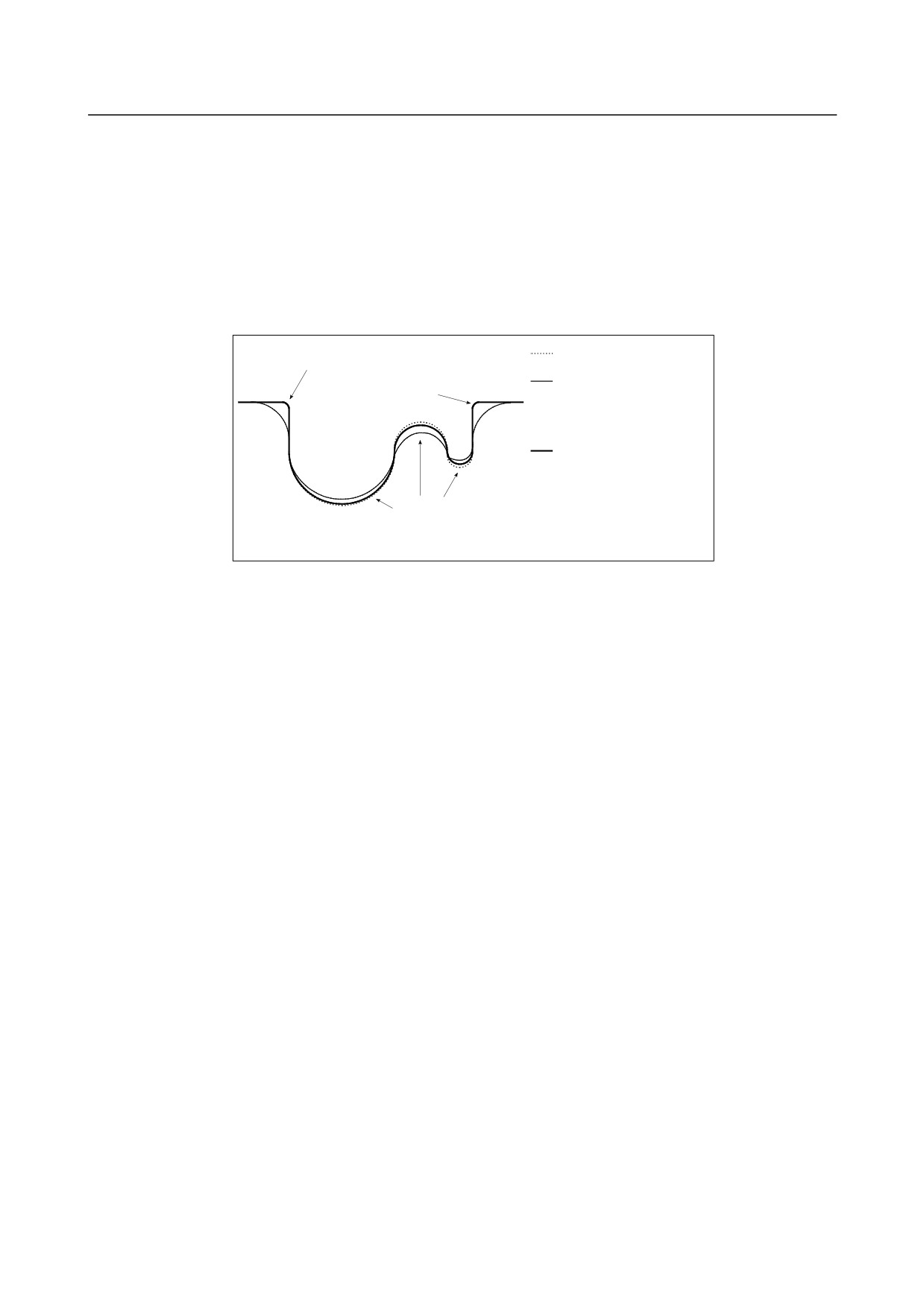
Automatic feedrate control function
During the advanced preview control, AI advanced preview control, or AI contour control (II) mode, the
feedrate is automatically controlled by reading blocks in advance.
The feedrate is determined using the following conditions. If the specified feedrate exceeds the
determined feedrate, acceleration/ deceleration before interpolation is performed to achieve the
determined feedrate.
<1> Feedrate changes on each axis at a corner and the permissible feedrate change that has been set
<2> Expected acceleration on each axis and the permissible acceleration that has been set
<3> Cutting load that is expected from the travel direction on the Z-axis
Specified tool path
The machining error is decreased
because of the deceleration by
Tool path when advanced
difference in feedrate.
preview control, AI
advanced preview control,
or AI contour control mode
is not used
Tool path when advanced
preview control, AI advanced
preview control, or AI
contour control mode is used
The machining error is decreased
because of the deceleration with
the acceleration.
-
Speed control based on the feedrate difference on each axis at a corner
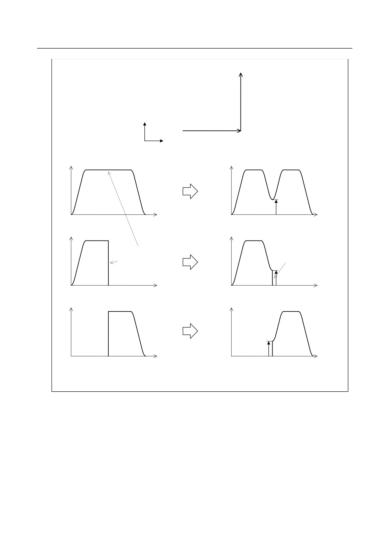
By using the speed control based on the feedrate difference on each axis at a corner, if a feedrate change
occurs on an axis on each axis at a corner, the feedrate is determined so that any feedrate difference
exceeding the permissible feedrate difference on that axis that has been set for parameter No. 1783 does
not occur, and deceleration is automatically performed.
- 250 -
16.HIGH-SPEED CUTTING
B-64304EN/02
PROGRAMMING
FUNCTIONS
(Example)
Program
N1 G01 G91 X100. F5000
N2 Y100.
N2
Y
N1
X
Tangent feedrate
Tangent feedrate
Time
The deceleration based
Parameter No.1783
on the feedrate difference
is used.
Time
X-axis feedrate
X-axis feedrate
The feedrate difference
becomes small, and the
The tangent feedrate is
feedrate on each axis
smooth, but the feedrate
becomes smooth.
on each axis is not.
Parameter No.1783
Time
Time
Y-axis feedrate
Y-axis feedrate
Parameter No.1783
Time
Time
When speed control based on the feedrate difference
When speed control based on the feedrate difference is
is invalid
valid
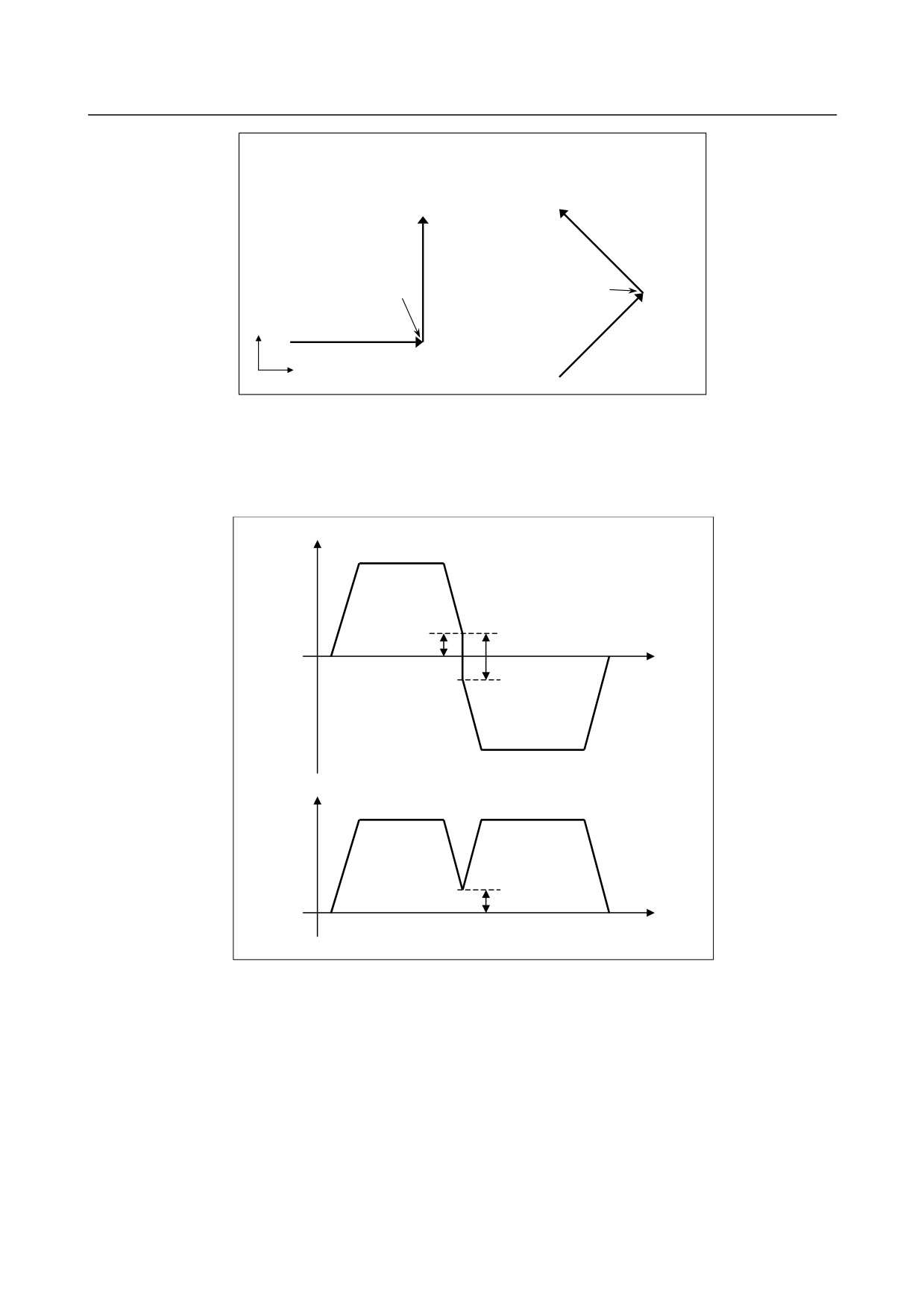
The method of deceleration based on the feedrate difference differs depending on the setting made for
parameter FNW (bit 6 of No. 19500).
If "0" is set, the largest feedrate that does not exceed the permissible feedrate difference set for parameter
No. 1783 is assumed to be the deceleration feedrate.
In this case, the deceleration feedrate differs if the travel direction differs, even if the shape is the same.
- 251 -
16. HIGH-SPEED CUTTING
FUNCTIONS
PROGRAMMING
B-64304EN/02
(Example)
If parameter FNW (bit 6 of No. 19500) = 0 and the
permissible feedrate difference = 500 mm/min (on all axes)
Decelerate the X/Y axis down to 250
mm/min
Decelerate the X axis
(The tangent direction feedrate is 354
down to 500 mm/min
mm/min.)
Y
X
In the left-side example in the figure above, the X axis is inverted at the corner from the position direction
to the negative direction, and deceleration is performed so that the feedrate difference becomes 500
mm/min. In other words, the feedrate is 250 mm/min both when the axis moves in the position direction
and when it moves in the negative direction. As a result, the tangent direction feedrate becomes 354
mm/min.
X-axis
feedrate
250mm/min
500mm/min
Time
Y-axis
feedrate
250mm/min
Time
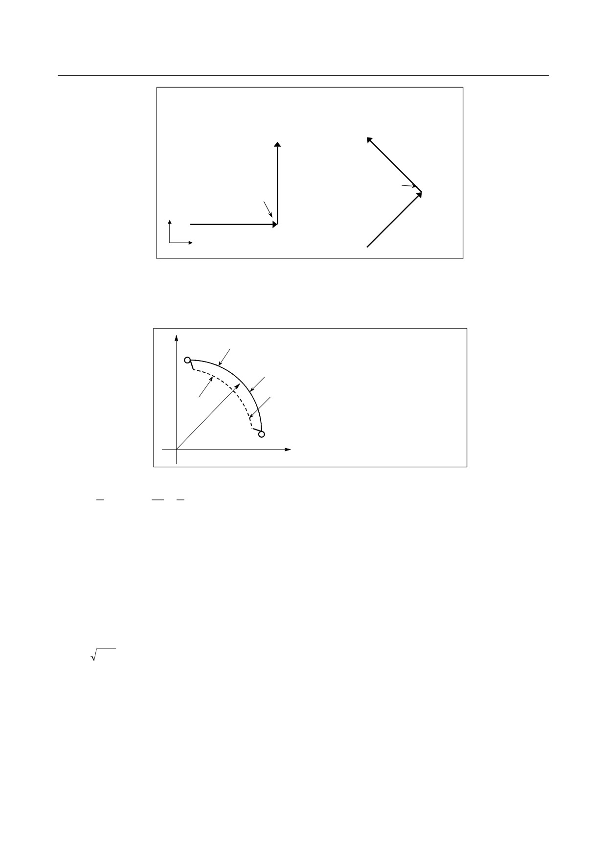
If "1" is set, the feedrate is determined not only with the condition that
the permissible feedrate difference and permissible acceleration on each axis are not exceeded, but also
that the deceleration feedrate is constant regardless of the travel direction if the shape is the same.
If 1 is set for this parameter, the deceleration feedrate determined with the feedrate difference may be up
to 30% lower than that determined if 0 is set.
- 252 -
16.HIGH-SPEED CUTTING
B-64304EN/02
PROGRAMMING
FUNCTIONS
(Example)
If parameter FNW (bit 6 of No. 19500) = 1 and
permissible feedrate difference = 500 mm/min (on all axes)
Decelerate the X/Y axis down to
250 mm/min
(The tangent direction feedrate is
Decelerate the X axis
354 mm/min.)
down to 354 mm/min
Y
X
-
Speed control with acceleration in circular interpolation
When high-speed cutting is performed in circular interpolation or helical interpolation, the actual tool
path has an error with respect to the programmed path. In circular interpolation, this error can be
approximated from the equation given below.
Y
Δr
: Error
Specified path Δr
: Maximum radius error (mm)
v
: Feedrate (mm/s)
r
: Arc radius (mm)
Actual path
a
: Acceleration (mm/s2)
T1
: Time constant of
acceleration/deceleration after
interpolation at cutting (s)
r
T2
: Time constant of servo motor (s)
0
X
2
1
2
2
v
1
2
2
Δr =
(T
+T
)
=
(T
+T
)⋅a
......................................................................................(Equation 1)
1
2
1
2
2
r
2
In actual machining, the permissible error Δr is given as the machining accuracy. Therefore, the
permissible acceleration a (mm/sec2) is determined by equation 1.
When a specified feedrate causes the radial error from an arc having a programmed radius to exceed the
permissible error, speed control with acceleration in circular interpolation automatically clamps the
arc-cutting feedrate by using parameter settings.
Let the permissible acceleration calculated from the permissible acceleration set for each axis be A.
Then, maximum permissible feedrate v with programmed radius r is expressed as follows:
v=
A⋅
r
...........................................................................................................................(Equation 2)
If a specified feedrate exceeds feedrate v obtained from equation 2, the feedrate is clamped at feedrate v
automatically.
The permissible acceleration is specified in parameter No. 1735. If there is a difference in permissible
acceleration between two axes for circular interpolation, the lower acceleration is regarded as the
permissible acceleration.
If the radius of an arc is small, too small value can be calculated as deceleration v. In such a case, the
lower feedrate limit can be set in parameter No. 1732 to prevent the feedrate from being decreased too
much.
- 253 -
16. HIGH-SPEED CUTTING
FUNCTIONS
PROGRAMMING
B-64304EN/02
M
-
Speed control with the acceleration on each axis
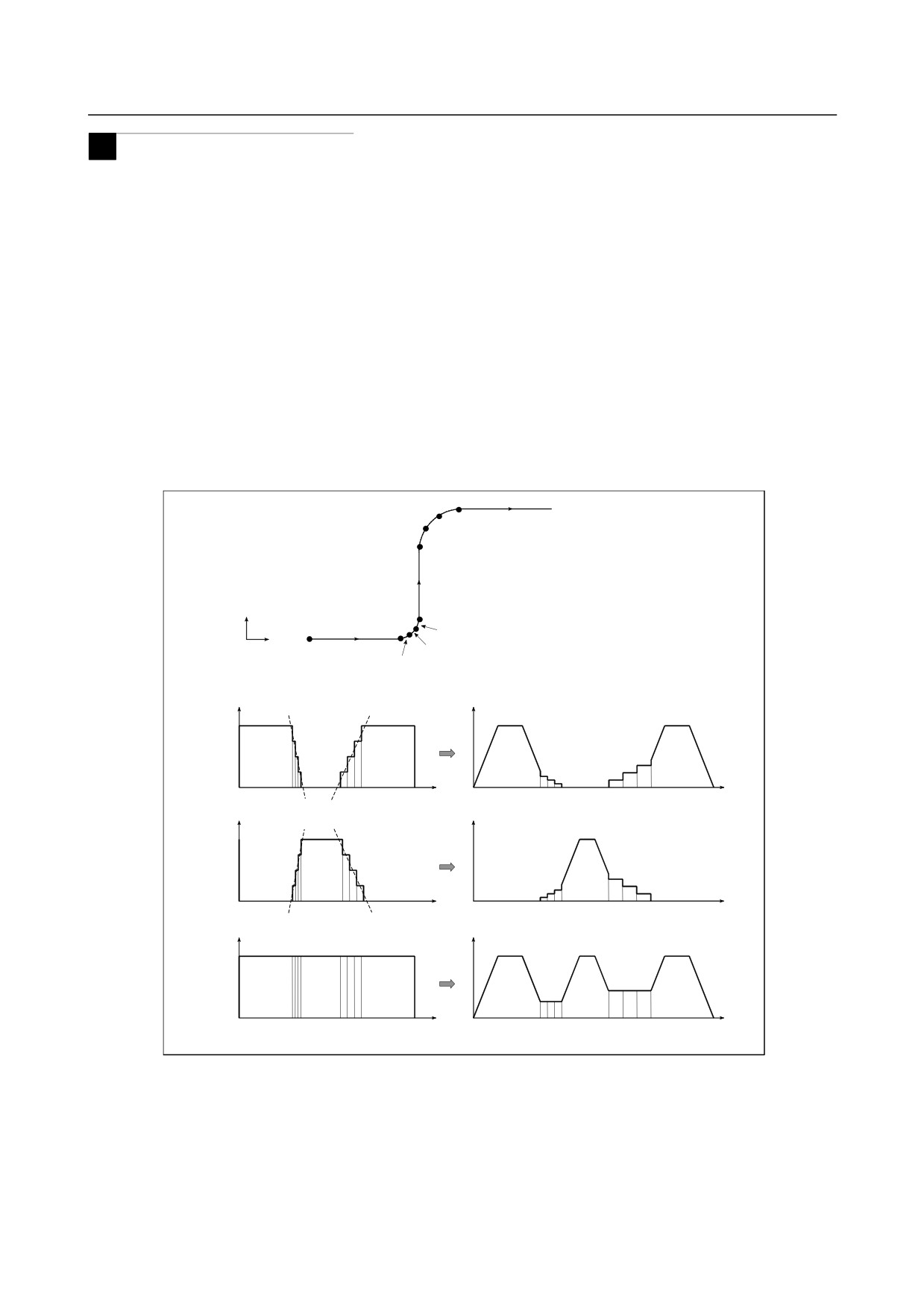
When consecutive small lines are used to form a curve, as in the example shown in the figure below, the
feedrate differences on each axis at the individual corners are not very large. Thus, deceleration with the
feedrate differences is not effective. Consecutive small feedrate differences, however, cause a large
acceleration on each axis, as a whole.
In such a case, deceleration can be performed to reduce the impact on the machine and the machining
error caused by too large an acceleration. The deceleration feedrate is determined to be the feedrate that
does not cause the acceleration on each axis to exceed the permissible acceleration set for parameter No.
1737.
The deceleration feedrate is determined for each corner. The actual feedrate is the smaller of the
deceleration feedrate determined at the start point of the block and that determined at the end point.
Depending on the specified figure, a very low deceleration feedrate may be calculated. In such a case,
the lower feedrate limit can be set in parameter No. 1738 to prevent the feedrate from being decreased too
much.
In the following example, the acceleration (gradient of the broken line in the feedrate graph) at too large
at corners N2 to N4 and N6 to N8 and, therefore, deceleration is performed.
N8
N7
N9
N6
N5
Y
N1
N4
X
N3
N2
X-axis
feedrate
Time
Time
Y-axis
feedrate
Time
Time
Tangent
feedrate
N1
N5
N9
N1
N5
N9
Time
Time
When speed control with the acceleration is invalid
When speed control with the acceleration is valid
The method of determining the feedrate with the acceleration differs depending on the setting of
parameter FNW (bit 6 of No. 19500).
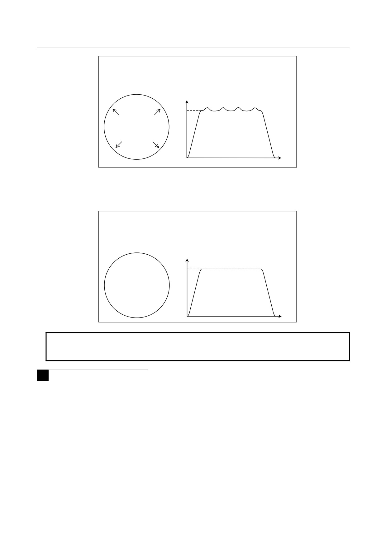
If "0" is set, the highest feedrate that does not cause the permissible acceleration set for parameter No.
1737 to be exceeded is assumed to be the deceleration feedrate. In this case, the deceleration feedrate
differs depending on the travel direction even if the shape is the same, as shown in the figure below.
- 254 -
16.HIGH-SPEED CUTTING
B-64304EN/02
PROGRAMMING
FUNCTIONS
(Example) If a circular shape with a radius of 10 mm is specified with small
line blocks
Parameter FNW (bit 6 of No. 19500) = 0
Permissible acceleration = 1000 mm/s2 (on all axes)
Tangent feedrate
F6000
The feedrate is
higher in these
directions.
Time
If "1" is set, the feedrate is determined with not only the condition that the permissible acceleration on
each axis is not exceeded but also the condition that the deceleration feedrate is constant regardless of the
travel direction if the shape is the same.
If
1 is set for this parameter, the deceleration feedrate determined with the feedrate difference or
acceleration may be up to 30% lower than that determined if 0 is set.
(Example) If a circular shape with a radius of 10 mm is specified with small
line blocks
Parameter FNW (bit 6 of No. 19500) = 1,
radius = 10 mm, permissible acceleration = 1000 mm/s2 (on all axes)
Tangent feedrate
F6000
The tangent
feedrate is
constant.
Time
NOTE
In circular interpolation, the tangent feedrate is constant regardless of the setting
of the parameter.
M
-
Smooth speed control
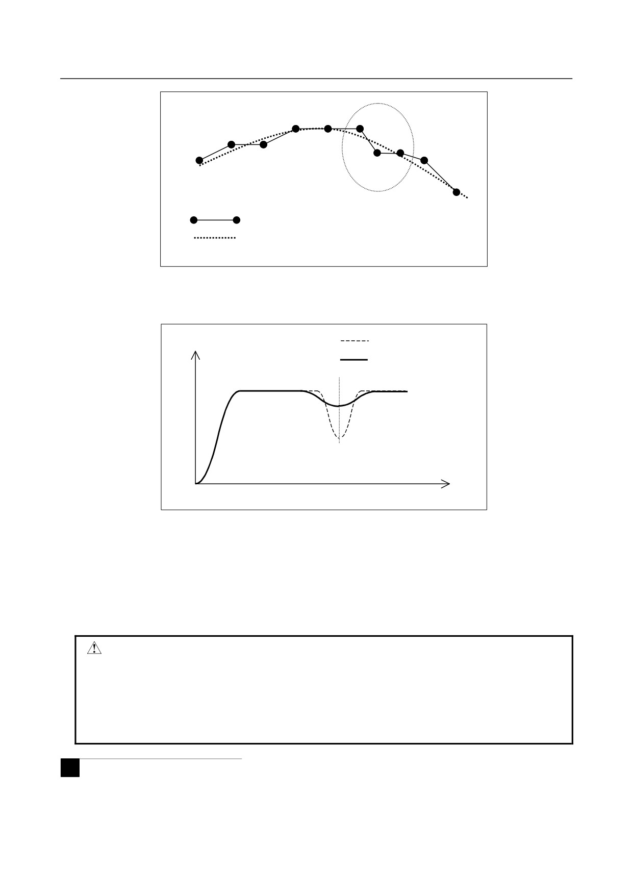
In speed control with acceleration, the smooth speed control function recognizes the entire figure from
preceding and following blocks including blocks read ahead to make a smooth feedrate determination.
When a curve is specified with successive minute straight lines, programmed values are rounded to the
least input increment before issued, so the machining profile is approximated with a broken line.
When the feedrate is determined with acceleration in an ordinary manner, an optimum feedrate is
automatically calculated exactly for a programmed figure, so a large acceleration may result depending on
the command, which can lead to deceleration.
In such a case, the use of smooth speed control enables speed control by recognizing the entire figure,
which provides smooth speed control while suppressing local deceleration, therefore increasing the
feedrate.
- 255 -
16. HIGH-SPEED CUTTING
FUNCTIONS
PROGRAMMING
B-64304EN/02
Large acceleration
: Programmed path
: Recognized figure
Also for a part of a programmed figure in which a large acceleration would be required, the acceleration
is obtained based on the figure recognized from multiple blocks, and the feedrate is determined so that the
acceleration is within the permissible acceleration set in parameter No. 1737.
Deceleration with acceleration
Tangential feedrate
in ordinary manner
Smooth speed control
Command with large acceleration
Time
Smooth speed control obtains the acceleration by using the figure recognized from the preceding and
following blocks including blocks read ahead, so smooth speed control is enabled even in parts in which
the acceleration increases.
Smooth speed control is enabled under the following conditions:
<1> Speed control with acceleration is enabled in the AI contour control II mode.
<2> Successive linear interpolation commands are specified.
<3> Bit 0 (HPF) of parameter No. 19503 is set to 1.
CAUTION
When smooth speed control is used, the feedrate in a certain figure such as a
corner may become larger than the feedrate obtained by ordinary speed control
with acceleration. For corners, set parameter No. 1783, which is the permissible
feedrate difference parameter for speed control with the feedrate difference at
corners, to perform appropriate deceleration by speed control with the corner
feedrate difference.
M
-
Speed control with the cutting load
Usually, the cutting resistance produced when machining is performed with the bottom of the cutter as the
tool lowers along the Z-axis is greater than the cutting resistance produced when machining is performed
with the side of the cutter as the tool rises along the Z-axis. Therefore, deceleration is required.
- 256 -
16.HIGH-SPEED CUTTING
B-64304EN/02
PROGRAMMING
FUNCTIONS
In AI contour control II, the tool travel direction on the Z-axis is used as a condition for calculating the
machining feedrate.
This function is enabled when bit 4 (ZAG) of parameter No. 8451 is set to 1.
During ascent on the Z-axis
θ
During descent on the Z-axis
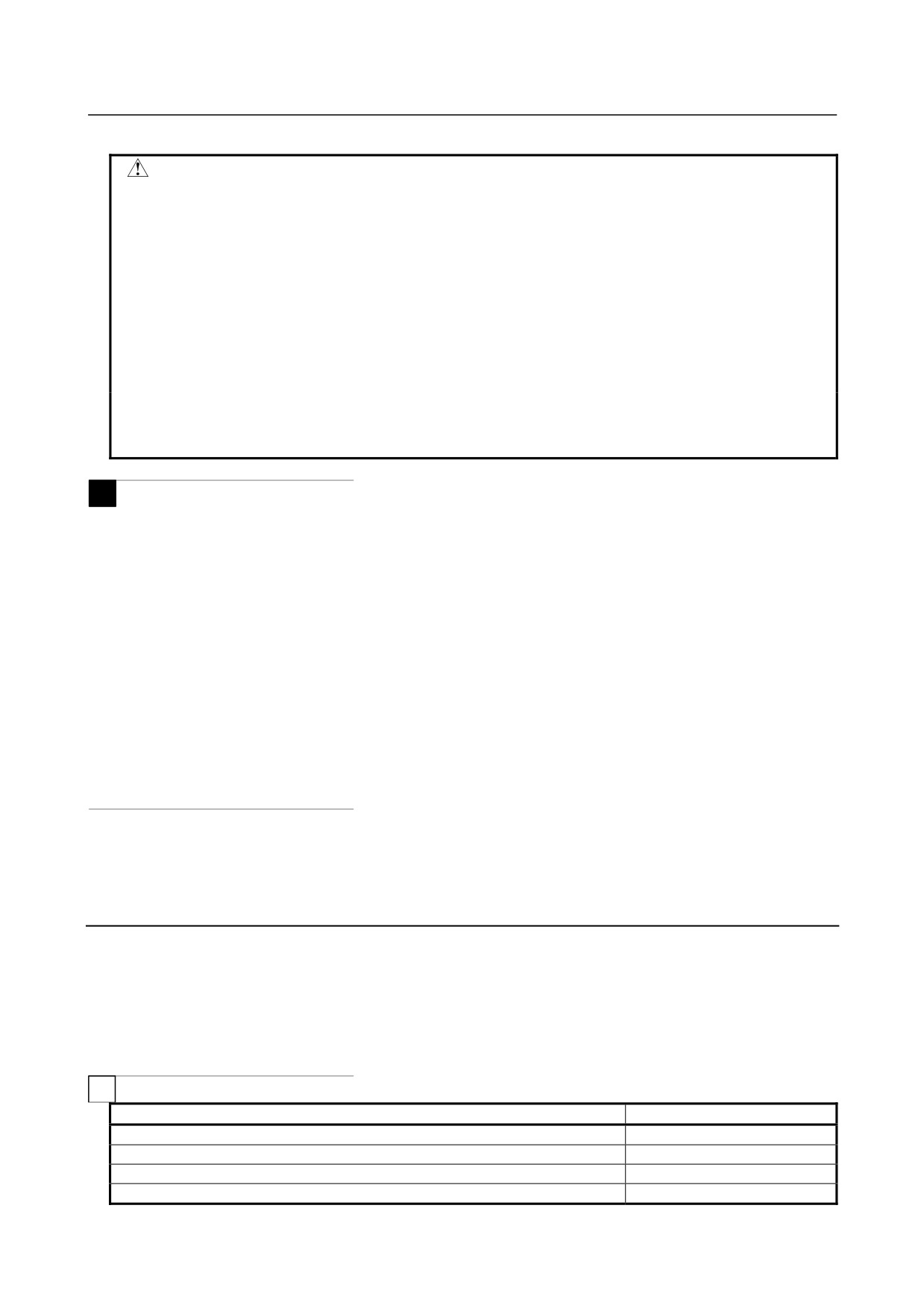
The descent angle θ during descent on the Z-axis (angle formed by the XY plane and the tool center path)
is as shown in the figure. The descent angle is divided into four areas, and the override values for the
individual areas are set for the following parameters:
Parameter No. 8456 for area 2
Parameter No. 8457 for area 3
Parameter No. 8458 for area 4
For area 1, however, no parameter is available, and an override of 100% is used at all times. The feedrate
obtained according to other feedrate control is multiplied by the override value of the area to which
descent angle θ belongs.
Area1
0º ≤ θ < 30º
Area2
30º ≤ θ < 45º
Area3
45º ≤ θ < 60º
Area4
60º ≤ θ < 90º
The feedrate can be overridden with an inclination by setting bit 1 (ZG2) of parameter No. 19515 to 1. In
this case, specify the override value for area 1 in parameter No. 19516.
Z
XY plane
30°
Area1
90°
60°
Area4
45°
Area2
Area3
- 257 -
16. HIGH-SPEED CUTTING
FUNCTIONS
PROGRAMMING
B-64304EN/02
CAUTION
1 The speed control with the cutting feed is effective only when the tool is parallel
with the Z-axis. Thus, it may not be possible to apply this function, depending on
the structure of the machine used.
2 In the speed control with the cutting feed, the travel direction on the Z-axis is
determined with the appropriate NC command. If, therefore, manual intervention
is performed on the Z-axis with manual absolute on, or if a mirror image is
applied on the Z-axis, the direction on the Z-axis cannot be determined. When
using the speed control with the cutting load, do not use these functions.
3 When performing 3-dimensional coordinate conversion, determine the descent
angle on the Z-axis using the converted coordinate system.
4 Speed control with the cutting load is enabled for all interpolations in the AI
contour control II mode. This function, however, can be made valid only for linear
interpolations by setting bit 4 (ZOL) of parameter No. 19503 to 1.
M
-
Ignoring feedrate commands
In a block in which AI contour control II is enabled, all feedrate commands (F commands) can be ignored
by setting bit 7 (NOF) of parameter No. 8451.
The term feedrate commands, as used here, refer to the following commands:
<1> Modal F commands before the block in which AI contour control II is enabled
<2> F commands and modal F commands in the block in which AI contour control II is enabled
When the feedrate commands are ignored, it is assumed that the upper feedrate limit specified for
parameter No. 8465 is specified.
Note, however, that any issued F commands and modal F commands are stored within the CNC.
Thus, in a block in which AI contour control II changes from the enabled state to the disabled state, the
modal values of the F commands described in <1> and <2> described above are used as modal F
commands, instead of the modal values of the F commands calculated by AI contour control II.
-
Another example of determining the feedrate
If a specified feedrate exceeds the upper feedrate limit of advanced preview control/AI advanced preview
control/AI contour control (II) (in parameter No. 8465), the feedrate is clamped at the upper feedrate.
The upper feedrate limit is clamped at the maximum cutting feedrate (parameter No. 1432).
Limitations
- Conditions for temporarily canceling the advanced preview control, AI advanced
preview control, or AI contour control (II) mode
If any of the commands listed below is executed during advanced preview control, AI advanced preview
control, or AI contour control (II) mode is temporarily canceled. Note that the advanced preview control,
AI advanced preview control, or AI contour control (II) mode resumes as soon as it becomes available.
T
Function name
G code
Positioning (rapid traverse) (NOTE 1)
G00
Spindle positioning
G00
Rigid tapping
G84,G88
Threading (NOTE 2)
G32
- 258 -
16.HIGH-SPEED CUTTING
B-64304EN/02
PROGRAMMING
FUNCTIONS
Function name
G code
Variable-lead threading (NOTE 2)
G34
Single threading cycle (NOTE 2)
G92
Multiple repetitive threading cycle (NOTE 2)
G76
When no move command is specified
-
G09
One-shot G code other than those shown at right (NOTE 1)
G38,G39
M
Function name
G code
Positioning (rapid traverse) (NOTE 1)
G00
Single direction positioning
G60
Rigid tapping
G74,G84
Threading (NOTE 2)
G33
Electronic gear box (EGB)
G81
When no move command is specified
-
G09
One-shot G code other than those shown at right (NOTE 1)
G38,G39
G45,G46,G47,G48
NOTE
1 If the first three conditions (1) to (3) below are all met, the mode is not canceled
even when the rapid traverse command is specified. If all the conditions (1) to
(5) are met, the mode is not canceled even when the G28, G30, or G53
command is specified.
(1) Bit 1 (LRP) of parameter No. 1401 is set to 1.
(Interpolation type positioning
is valid.)
(2) Parameter No. 1671 (maximum acceleration during rapid traverse) is set.
(3) Bit 5 (FRP) of parameter No. 19501 is set to 1 (acceleration/deceleration
before interpolation is valid for rapid traverse).
(4) Bit 4 (ZRL) of parameter No. 1015 is set to 1 (the G28, G30, and G53
commands are of the interpolation type).
(5) Bit 1 (AMP) of parameter No. 11240 is set to 1 (acceleration/deceleration
before interpolation is valid for the G28, G30, and G53 commands in the
high-speed, high-precision mode).
2 Acceleration/deceleration before interpolation is invalid for a threading
command. Therefore, if acceleration/deceleration before interpolation is
enabled by a command that precedes or follows a threading command, the tool
is decelerated and stopped temporarily when the block changes.
Since the state of acceleration/deceleration before interpolation does not change
during continuous threading, deceleration does not occur when the block
changes.
-
Parameter list
Positioning
Parameter No.
Parameter
Advanced
AI advanced
AI contour
preview control
preview control
control (II)
Positioning type (non-linear (0)/interpolation (1))
1401#1 LRP
- 259 -

16. HIGH-SPEED CUTTING
FUNCTIONS
PROGRAMMING
B-64304EN/02
Parameter No.
Parameter
Advanced
AI advanced
AI contour
preview control
preview control
control (II)
Acceleration/deceleration type (acceleration constant
1603#4 PRT
(0)/time constant (1))
Acceleration/deceleration type (after interpolation (0)/before
19501#5 FRP
interpolation (1))
Time constant of acceleration/deceleration after interpolation
1620
in rapid traverse
Time constant of bell-shaped acceleration/deceleration after
1621
interpolation in rapid traverse
Maximum permissible acceleration of
1671
acceleration/deceleration after interpolation in rapid traverse
Acceleration change time of bell-shaped
acceleration/deceleration before interpolation in rapid
1672
traverse
Acceleration/deceleration before interpolation
Parameter No.
Parameter
Advanced
AI advanced
AI contour
preview control
preview control
control (II)
Maximum permissible acceleration of
1660
acceleration/deceleration before interpolation
Acceleration change time of bell-shaped
None
1772
acceleration/deceleration before interpolation
Valid/invalid state of the function for changing time constant
7055#3
None
of bell-shaped acceleration/deceleration before interpolation
BCG
Reference acceleration/deceleration speed for the function
for changing time constant of bell-shaped
None
7066
acceleration/deceleration before interpolation
Acceleration/deceleration after interpolation
Parameter No.
Parameter
Advanced
AI advanced
AI contour
preview control
preview control
control (II)
Acceleration/deceleration type of acceleration/deceleration
1602#3 BS2, 1602#6 LS2
after interpolation in cutting feed
FL rate of acceleration/deceleration after interpolation in
1763
cutting feed
Time constant of acceleration/deceleration after interpolation
1769
in cutting feed
Speed control based on the feedrate difference on each axis
Parameter No.
Parameter
Advanced
AI advanced
AI contour
preview control
preview control
control (II)
Permissible feedrate difference when determining the
1783
feedrate based on the feedrate difference at a corner
Method of determining the feedrate based on the feedrate
19500#6 FNW
difference or based on the acceleration
- 260 -

16.HIGH-SPEED CUTTING
B-64304EN/02
PROGRAMMING
FUNCTIONS
Speed control with acceleration in circular interpolation
Parameter No.
Parameter
Advanced
AI advanced
AI contour
preview control
preview control
control (II)
Lower-limit feedrate for the deceleration function with the
1732
acceleration in circular interpolation
Permissible acceleration for the deceleration function with
1735
the acceleration in circular interpolation
M
Speed control with the acceleration on each axis
Parameter No.
Parameter
Advanced
AI advanced
AI contour
preview control
preview control
control (II)
Permissible acceleration for the deceleration function with
None
1737
the acceleration
Lower-limit feedrate for the deceleration function with the
None
1738
acceleration
Method of determining the feedrate based on the feedrate
None
19500#6 FNW
difference or based on the acceleration
Others
Parameter No.
Parameter
Advanced
AI advanced
AI contour
preview control
preview control
control (II)
Maximum cutting feedrate during the mode of
1432
acceleration/deceleration before interpolation
Upper-limit feedrate for advanced preview control, AI
8465
advanced preview control, or AI contour control (II)
Upper-limit feedrate for advanced preview control, AI
advanced preview control, or AI contour control (II) (when
8466
only the rotation axis is specified)
16.2 MACHINING CONDITION SELECTING FUNCTION
Overview
By setting a speed- or precision-focused parameter set in an advanced preview control (T series) / AI
advanced preview control (M series) / AI contour control (II) (M series) function and specifying a
precision level in accordance with the machining conditions during machining, parameters suitable to the
conditions can be automatically calculated so that machining can be performed.
This function is an optional one.
Format
-
Changing the precision level using a program
In addition to being switched on the precision level selection screen, the precision level can be changed
using a program in the format below.
- 261 -
16. HIGH-SPEED CUTTING
FUNCTIONS
PROGRAMMING
B-64304EN/02
T
For advanced preview control
G08 P1 Rx ;
x
Level (1 to 10)
CAUTION
Once specified, a level remains effective even if the advanced preview control
mode is canceled.
M
For AI advanced preview control/AI contour control (II)
G05.1 Q1 Rx ;
x
Level (1 to 10)
CAUTION
Once specified, a level remains effective even if the AI advanced preview control
/ AI contour control (II) mode is canceled.
16.3 MACHINING QUALITY LEVEL ADJUSTMENT (M Series)
M
Overview
In nano smoothing, if the “level 1” and “level 10” parameters of a precision level and smoothing level are
set in order to specify a precision level and smoothing level according to the machining condition during
machining, the parameter values corresponding to the condition can be automatically calculated for
machining.
On the machining quality level adjustment screen, the machining quality/precision/speed level in nano
smoothing can easily be adjusted.
This function is an optional function.
Format
-
Changing the smoothing level by a program
The smoothing level can be switched on the machining level selection screen or machining quality level
adjustment screen; it can also be changed by a program with the following format.
G05.1 Q3 Rx ;
x
Level (1 to 10)
CAUTION
Once a level is specified, it remains valid even after the nano smoothing mode is
canceled.
-
Changing the precision level by a program
For information on the changing the precision level by a program, see Section 16.2, "MACHINING
CONDITION SELECTION FUNCTION".
- 262 -
16.HIGH-SPEED CUTTING
B-64304EN/02
PROGRAMMING
FUNCTIONS
16.4 JERK CONTROL (M Series)
M
16.4.1 Speed Control with Change of Acceleration on Each Axis
Overview
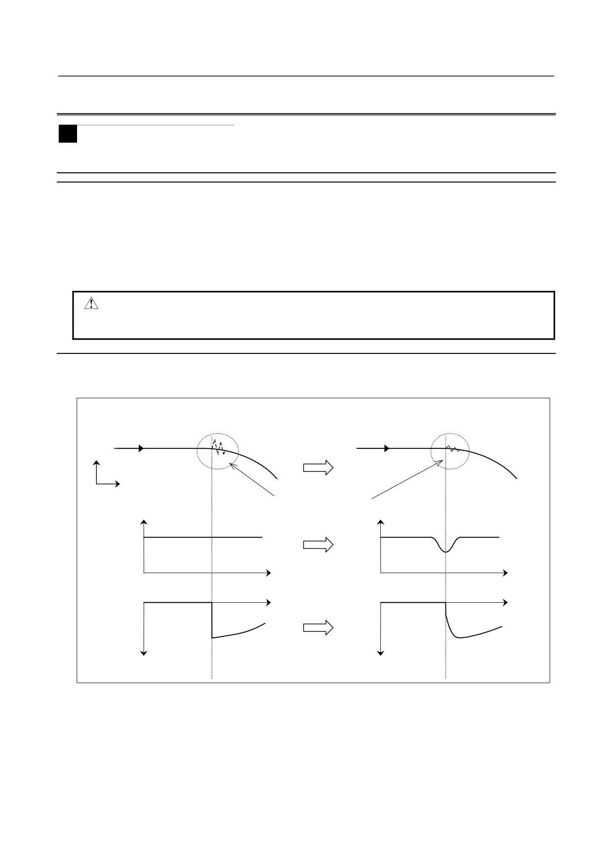
In portions in which acceleration changes largely, such as a portion where a programmed figure changes
from a straight line to curve, vibration or shock on the machine may occur. Speed control with change of
acceleration on each axis is a function to suppress machining errors due to vibration and machine shock
generated by change of acceleration. This function obtains a feedrate so that change of acceleration is
within the parameter-set permissible acceleration change amount for each axis, and performs deceleration
by using acceleration/deceleration before interpolation.
CAUTION
Before speed control with change of acceleration on each axis can be used, the
options for jerk control and AI contour control II are required.
Explanation
In the following example, the Y-axis acceleration changes largely at the contact point between a linear
interpolation and circular interpolation, so deceleration is performed.
From linear interpolation (N1) to circular interpolation (N2)
Y
N1
N1
N2
N2
X
Vibration due to change
of acceleration
Feedrate
Feedrate
Tangential
feedrate
Time
Time
Time
Time
Y-axis
acceleration
Acceleration
Acceleration
-
Setting the permissible acceleration change amount
The permissible acceleration change amount for each axis is set in parameter No. 1788. When 0 is set in
this parameter for a certain axis, speed control with change of acceleration is not performed for that axis.
• Parameter setting example
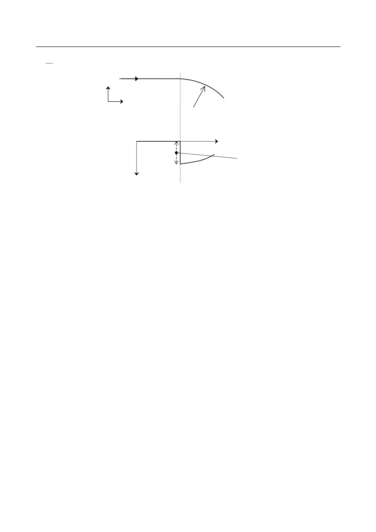
Suppose a figure shown below in which a straight line is followed by an arc. Let the specified feedrate
and the arc radius be 6000 mm/min and 10 mm, respectively. Then, the Y-axis acceleration change
amount at the contact point of the linear and arc portions is obtained as follows:
- 263 -
16. HIGH-SPEED CUTTING
FUNCTIONS
PROGRAMMING
B-64304EN/02
2
v
2
=1000mm
/
s
r
From straight line to arc
Y
Specified feedrate:
6000 mm/min
X
Arc radius:
10 mm
Time
Y-axis
Acceleration
acceleration
change amount:
1000 mm/s2
Acceleration
To suppress the change of acceleration to 300 mm/s2, set 300 mm/s2 for the Y-axis in parameter No. 1788.
Note that the change of acceleration is determined from the interpolation data of the CNC, so it may differ
from the theoretical value.
The actual machine is affected by acceleration/deceleration and other factors, so the value to be set in the
parameter should be determined after adjustments are made.
-
For successive linear interpolations
When there are successive linear interpolations, speed control with change of acceleration obtains the
deceleration feedrate from the change in acceleration between the start point and end point of a specified
block.
When a curve is specified using successive minute straight lines, programmed values are rounded to the
least input increment before issued, so the machining profile is approximated with a broken line. The
error due to rounding may increase change of acceleration, and especially when the line segments
specified by blocks are short, deceleration is performed frequently. As a result, the machining speed
cannot increase enough. In such a case, a relatively large value should be set in parameter No. 1789 as the
permissible acceleration change amount for each axis in successive linear interpolations to improve the
machining speed.
When a value other than 0 is set in parameter No. 1789 for an axis for which deceleration with change of
acceleration is enabled, this setting is regarded as the permissible acceleration change amount at corners
in which linear interpolations meet. (For portions where a linear interpolation and circular interpolation
meet and where circular interpolations meet, the setting in parameter No. 1788 is used.)
When 0 is set in parameter No. 1789 for an axis, the setting in parameter No. 1788 specifying the
ordinary permissible acceleration change amount is used even at a corner in which linear interpolations
meet.
When smooth speed control is used in speed control with permissible acceleration in AI contour control II,
the deceleration feedrate is obtained from the change of acceleration calculated by smooth speed control.
Therefore, the deceleration feedrate may be higher than the ordinary deceleration feedrate.
- 264 -
16.HIGH-SPEED CUTTING
B-64304EN/02
PROGRAMMING
FUNCTIONS
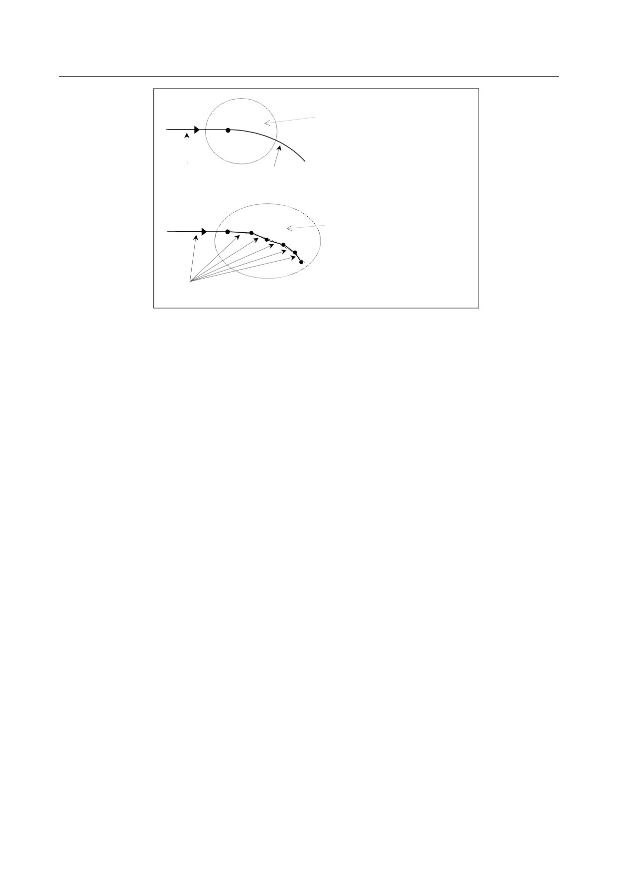
When linear interpolation is followed
by circular interpolation, speed
control is performed using the
permissible acceleration change
amount set in parameter No. 1788.
Linear
Circular
interpolation
interpolation
For successive linear interpolations,
speed control is performed using the
permissible acceleration change
amount set in parameter No. 1789.
Linear
interpolation
- 265 -
16. HIGH-SPEED CUTTING
FUNCTIONS
PROGRAMMING
B-64304EN/02
16.4.2 Look-Ahead Smooth Bell-Shaped Acceleration/Deceleration
before Interpolation
Overview
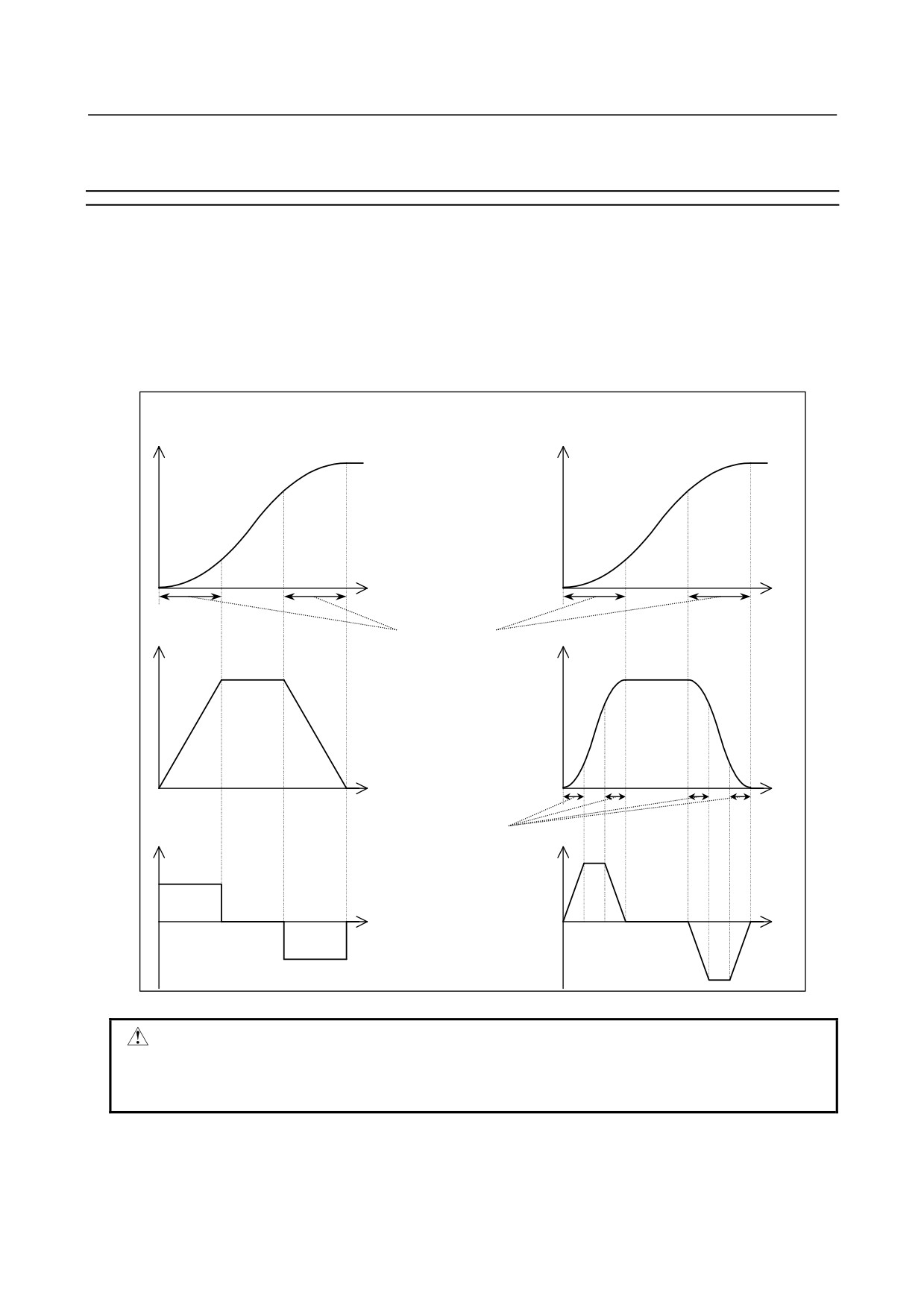
In look-ahead bell-shaped acceleration/deceleration before interpolation performs smooth
acceleration/deceleration by changing the acceleration at a constant rate in specified acceleration change
time.
In look-ahead smooth bell-shaped acceleration/deceleration before interpolation, the jerk change time is
specified in parameter No. 1790 by using the percentage to the acceleration change time for look-ahead
bell-shaped acceleration/deceleration before interpolation, and change of acceleration is also controlled so
that the change is bell-shaped. This enables smoother acceleration/deceleration, therefore reducing
machine vibration and shock due to acceleration/ deceleration.
(Look-ahead bell-shaped
(Look-ahead smooth bell-shaped
acceleration/deceleration before interpolation)
acceleration/deceleration before interpolation)
Tangential feedrate
Tangential feedrate
Time
Time
Acceleration
Acceleration
Acceleration change time
Time set in parameter No.
1772
Time
Time
Jerk
Jerk change time
Jerk
acceleration
Time set in parameter No.
acceleration
1790 by using the
percentage to the
acceleration change time
Time
Time
CAUTION
Before look-ahead smooth bell-shaped acceleration/deceleration before
interpolation can be used, the option for jerk control and AI contour control II is
required.
- 266 -
16.HIGH-SPEED CUTTING
B-64304EN/02
PROGRAMMING
FUNCTIONS
Explanation
-
Setting the jerk change time
The jerk change time is set in parameter No. 1790 by using the percentage to the acceleration change
time.
The actual jerk change time is represented by the percentage to the acceleration change time set in
parameter No. 1772.
The jerk change time must be within a half of the acceleration change time, so the value to be set in the
parameter ranges 0 to 50 (percent).
If
0 or a value beyond the specifiable range is specified in parameter No. 1790, look-ahead smooth
bell-shaped acceleration/deceleration before interpolation is not enabled.
-
Acceleration/deceleration before interpolation for linear type rapid traverse
When bell-shaped acceleration/deceleration is used in acceleration/
deceleration before interpolation for linear type rapid traverse, enabling look-ahead smooth bell-shaped
acceleration/deceleration before interpolation applies smooth bell-shaped acceleration/deceleration to
acceleration/deceleration before interpolation for linear type rapid traverse.
In this case, the jerk change time is represented by the percentage set in parameter No. 1790 to the
acceleration change time set in parameter No. 1672.
- 267 -
17.AXIS CONTROL FUNCTIONS PROGRAMMING
B-64304EN/02
17 AXIS CONTROL FUNCTIONS
Chapter 21, "AXIS CONTROL FUNCTIONS", consists of the following sections:
17.1 AXIS SYNCHRONOUS CONTROL
268
17.2 ROTARY AXIS ROLL-OVER
277
17.3 ARBITRARY ANGULAR AXIS CONTROL
278
17.4 TANDEM CONTROL
287
17.1 AXIS SYNCHRONOUS CONTROL
Overview
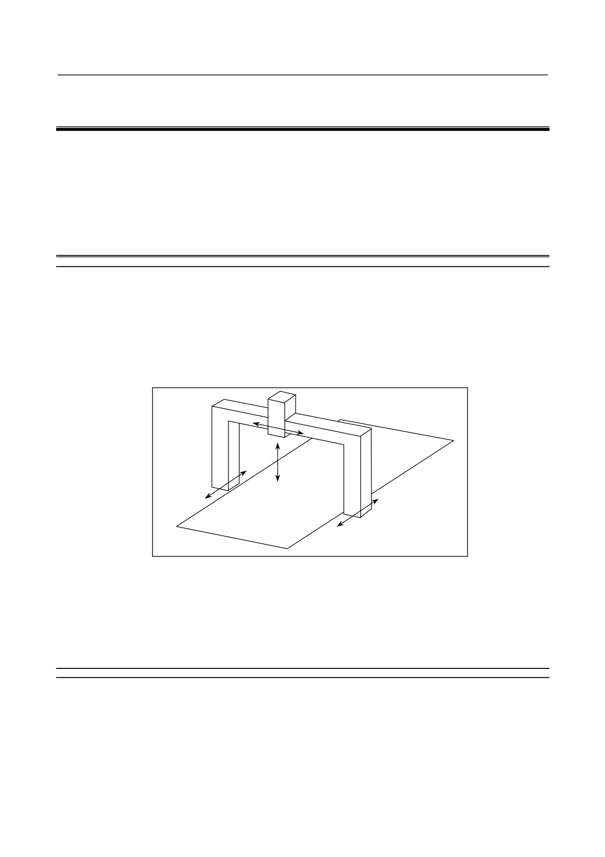
When a movement is made along one axis by using two servo motors as in the case of a large gantry
machine, a command for one axis can drive the two motors by synchronizing one motor with the other.
When a synchronous error exceeding a set value occurs, a synchronous error check can be made to issue
an alarm and stop a movement along the axis.
An axis used as the reference for axis synchronous control is referred to as a master axis (M-axis), and an
axis along which a movement is made in synchronism with the master axis is referred to as a slave axis
(S-axis).
Y
Z
A
(Slave axis)
X
(Master axis)
Fig. 17.1 (a) Example of machine with X and A being synchronous axes
The synchronous establishment function can be used for automatic compensation to eliminate a machine
coordinate error in cases such as emergency stop cancellation.
An external signal can be used to turn synchronization on and off.
17.1.1 Axis Configuration for Axis Synchronous Control
Explanation
-
Master axis and slave axis for axis synchronous control
An axis used as the reference for axis synchronous control is referred to as a master axis (M-axis), and an
axis along which a movement is made in synchronism with the master axis is referred to as a slave axis
(S-axis).
By setting the axis number of a master axis in the parameter No. 8311 of the slave axis, the axis
configuration for axis synchronous control is determined.
- 268 -
B-64304EN/02
PROGRAMMING
17.AXIS CONTROL FUNCTIONS
-
Synchronous operation and normal operation
Operation where axis synchronous control is turned on (enabled) to make a movement along the slave
axis in synchronism with the master axis is referred to as synchronous operation. Operation where axis
synchronous control is turned off (disabled) to make movements along the master axis and slave axis
independently of each other is referred to as normal operation.
(Example)
Automatic operation when the master axis is the X-axis and the slave axis is the A-axis
In synchronous operation, movements are made along the X-axis and A-axis according to the
programmed command Xxxxx for the master axis.
In normal operation, movements are made along the master axis and slave axis independently of
each other as in the case of normal CNC control. The programmed command Xxxxx makes a
movement along the X-axis. The programmed command Aaaaa makes a movement along the
A-axis. The programmed command Xxxxx Aaaaa makes movements along the X-axis and A-axis
at the same time.
The mode of operation can be switched between synchronous operation and normal operation by an input
signal, or synchronous operation can be performed at all times. Which mode to use can be set using bit
5 (SCA) of parameter No. 8304.
-
Switching between synchronous operation and normal operation by using an
input signal
When bit 5 (SCA) of parameter No. 8304 is set to 0 for the slave axis, the signal SYNCx/SYNCJx (with x
representing a slave axis number) is used to switch between synchronous operation and normal operation.
When SYNCx/SYNCJx = 1, synchronous operation is selected. When SYNCx/SYNCJx = 0, normal
operation is selected.
During feed axis synchronization control, the output signal SYNOx is set to "1".
-
Setting for using synchronous operation at all times
When bit 5 (SCA) of parameter No. 8304 for the slave axis is set to 1, synchronous operation is
performed at all times, regardless of the setting of the signal SYNCx/SYNCJx.
-
Synchronous control axis name
The name of a master axis and the name of a slave axis may be the same or may be different from each
other.
-
Restrictions on using the same name for the master axis and slave axis
If the same axis name is assigned to the master axis and slave axis, manual operation only is allowed in
normal operation. Automatic operation cannot be performed.
-
Setting of an axis name subscript
A subscript can be attached to an axis name like X1, X2, XM, and XS. If the same axis name is used for
multiple axes, and a unique subscript is assigned to each of those axes, the axes can be distinguished from
each other on the screen display, or which of those axes issued an alarm can be identified.
Set a subscript in parameter No. 3131.
-
Setting of multiple slave axes
One master axis can have multiple slave axes.
(Example)
In the example below, movements along the X1-axis and X2-axis are made in synchronism with the
XM-axis.
- 269 -

17.AXIS CONTROL FUNCTIONS PROGRAMMING
B-64304EN/02
Controlled
Axis name
Subscript
Axis name
Master axis number
axis
Parameter
Parameter
Operation
indication
Parameter (No.8311)
number
(No. 1020)
(No.3131)
XM
1
88
77
0
Y
2
89
0
0
A movement is made in
X1
3
88
49
1
synchronism with the XM-axis.
A movement is made in
X2
4
88
50
1
synchronism with the XM-axis.
When one master axis has multiple slave axes, synchronous establishment, and synchronous error check
are performed for each slave axis independently.
-
Combination with tandem control
Tandem control can be used with each of the master and slave axes. The same restriction on axis
arrangement as imposed in the case of normal tandem control is imposed. No particular restriction is
imposed on axis synchronous control.
-
Axis selection on the screen display
On a screen such as the current position display screen, a slave axis is also displayed. The display of a
slave axis can be disabled by setting bit 0 (NDP) of parameter No. 3115 to 1 and setting bit 1 (NDA) of
parameter No. 3115 to 1.
-
Axis selection in actual cutting feedrate display
By setting bit 2 (SAF) of parameter No. 8303 to 1 for a slave axis, the slave axis can be included in an
actual cutting feedrate display calculation during synchronous operation.
-
Axis synchronous control with an absolute-position detector
When bit 7 (SMA) of parameter No. 8302 is set to 1 to attach an absolute-position detector, and bit 4
(APZ) of parameter No. 1815 for an axis placed in synchronous operation is turned off, APZ for the axis
(axes) placed together in synchronous operation is also turned off.
-
Slave axis mirror image
By setting parameter No. 8312, a mirror image can be applied to a slave axis placed in synchronous
operation. When the mirror image function is enabled, the direction in which the absolute and relative
coordinates change is the same as for the machine coordinates.
At this time, synchronization establishment, synchronization error check, and correction mode cannot be
used.
The mirror image set by bit 0 (MIR) of parameter No. 0012 cannot be applied to the slave axis. Because
this mirror image differs from the mirror image set by parameter MIR, it does not affect input signal MIx
<G106> or output signal MMIx <F108>.
-
External machine coordinate system shift
Bit 7 (SYE) of parameter No. 8304 can be set to 1 for the slave axis to shift the slave axis by the same
amount as specified for the master axis when external machine coordinate system shift is specified by
external data input/output for the master axis in synchronous control.
-
Manual operation to slave axis
The move command cannot be performed to the slave axis in axis synchronous control with manual
operation (JOG feed, HANDLE feed, etc.).
- 270 -
B-64304EN/02
PROGRAMMING
17.AXIS CONTROL FUNCTIONS
17.1.2 Synchronous Establishment
Explanation
Upon power-up or after emergency stop cancellation, the machine positions on the master axis and slave
axis under axis synchronous control are not always the same. In such a case, the synchronous
establishment function matches the machine position on the master with that on the slave axis.
-
Synchronous establishment based on machine coordinates
Enable synchronous establishment based on machine coordinates by setting bit 7 (SOF) of parameter No.
8303 to 1. This method of synchronous establishment outputs the machine coordinate difference between
the master axis and slave axis as command pulses for the slave axis to establish synchronization. A
machine coordinate difference is output at a time as command pulses. So, if the compensation value is
large, the machine abruptly makes a large movement. Taking this into consideration, set a maximum
allowable compensation value to be used for synchronous establishment in parameter No. 8325. As a
maximum allowable compensation value, set a maximum allowable value by which the machine may
move abruptly. If a compensation value is larger than the value set in this parameter, an alarm SV0001
is issued, and synchronous establishment is not performed. Moreover, when parameter No. 8325 is set
to 0, synchronous establishment is not performed.
The result of comparing the positional difference between the master axis and slave axis with a maximum
allowable compensation value for synchronous establishment can be checked using the synchronous
establishment enable state output signal SYNOF <F0211>.
-
First synchronous establishment after power-up
Two methods of performing the first synchronous establishment after power-up are available. One
method is based on manual reference position return operation, and the other is based on absolute position
detection.
A synchronization error value is checked until this synchronous establishment is completed.
-
Synchronous establishment based on manual reference position return
operation
When manual reference position return operation is performed along axes under axis synchronous control,
the machine is placed at the reference position on the master axis and slave axis according to the same
sequence as for normal reference position return operation.
The sequence is the same as the grid method for one axis only. However, only the deceleration signal
for the master axis is used. When the deceleration signal is set to 0, the machine gradually stops along
the master axis and slave axis, then an FL feedrate is set. When the deceleration signal is set to 1, the
machine moves to a grid point along each of the master axis and slave axis, then stops.
- 271 -
17.AXIS CONTROL FUNCTIONS PROGRAMMING
B-64304EN/02
NOTE
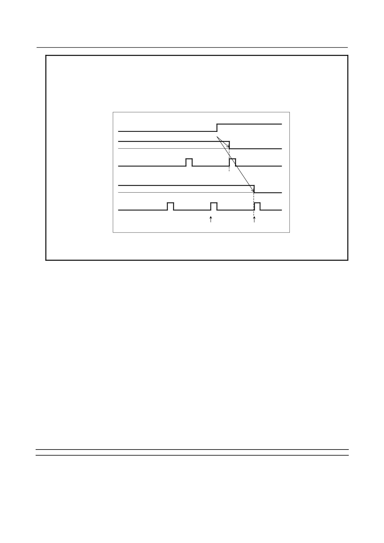
When the grid position difference between the master axis and slave axis is
large, a reference position shift can occur, depending on the timing of the *DEC
signal set to 1. In the example below, the shift along the slave axis is so large
that the position shifted one grid point from the actual reference position is
regarded as the reference position.
(Example) When the reference position on the slave axis is shifted one grid point
*DEC
Master axis feedrate
Master axis grid
Actual reference position
Slave axis feedrate
Slave axis grid
Actual reference position
Stop at position shifted one
grid point
In such a case, match the grid position according to Subsection 17.1.3,
"Automatic Setting for Grid Position Matching."
-
Synchronous establishment based on absolute position detection
When an absolute-position detector is used as the position detector, the machine positions on the master
axis and slave axis are found at power-up time for automatic establish synchronization.
-
Synchronous establishment after emergency stop cancellation, etc.
Synchronous establishment is also performed when servo position control is turned on, for example, at
emergency stop cancellation, servo alarm cancellation, or servo-off cancellation time.
However, synchronous establishment is not performed at the time of axis removal cancellation. So,
synchronous establishment based on manual reference position return operation is required as in the case
of power-up time.
-
One-direction synchronous establishment
Synchronous establishment can be performed by setting bit 0 (SSO) of parameter No. 8305 to 1 to move
the machine in one direction along the master axis and slave axis. The move direction depends on the
reference position setting based on bit 0 (SSA) of parameter No. 8304. When SSA = 0, for example, the
machine coordinate on the master axis or slave axis, whichever larger, is used as the reference point. So,
the machine moves in the + direction along the axes.
When bit 1 (SSE) of parameter No. 8305 is set to 1, normal synchronous establishment is performed
instead of one-direction synchronous establishment after an emergency stop.
17.1.3 Automatic Setting for Grid Position Matching
Explanation
Before axis synchronous control can be performed, the reference position on the master axis must be
matched with the reference position on the slave axis. With this function, the CNC automatically
matches the reference positions (grid positions) on the master axis and slave axis under axis synchronous
control.
- 272 -
B-64304EN/02
PROGRAMMING
17.AXIS CONTROL FUNCTIONS
[Operation procedure]
The procedure below is usable when bit 0 (ATE) of parameter No. 8303 is set to 1.
1.
Set bit 1 (ATS) of parameter No. 8303 to 1.
2.
Turn off the power then turn on the power.
3.
Set the REF mode (or JOG mode in the case of reference position setting without dogs) when
synchronous operation is ready, and make movements in the reference position return direction
along the master axis and slave axis.
4.
The movements along the master axis and slave axis automatically stop, and a grid difference value
is set in parameter No. 8326. At this time, bit 1 (ATS) of parameter No. 8303 is set to 0, and the
power-off request alarm PW0000 is issued.
5.
Turn off the power then turn on the power again.
6.
Perform normal reference position return operation.
NOTE
1 Parameter setting
When bit 1 (ATS) of parameter No. 8303 is set, bit 4 (APZ) of parameter No.
1815 and parameter No. 8326 for the master axis and slave axis are set to 0.
When the operator sets parameter No. 8326 (MDI, G10L50), bit 0 (ATE) of
parameter No. 8303 is set to 0.
2 This function cannot be used together with the reference position shift function.
17.1.4 Synchronous Error Check
Explanation
A synchronous error value is monitored at all times. If an error exceeding a certain limit is detected, an
alarm is issued and the movement along the axis is stopped.
A synchronous error check based on machine coordinates and a synchronous error check based on a
positional deviation value are performed.
-
Synchronous error check based on machine coordinates
A synchronous error check based on machine coordinates is made.
The machine coordinate on the master axis is compared with that on the slave axis. When the error
between the machine coordinates exceeds the value set in parameter No. 8314, the SV0005 alarm is
issued, and the motor is stopped immediately.
A check can be made even in the emergency stop, servo off, and servo alarm states.
A synchronous error check is performed during normal operation as well as during synchronous operation.
So, even if the axis synchronous control selection signal (SYNCx) or the axis synchronous control
manual feed selection signal (SYNCJx) is set to 0 by mistake during synchronous operation, damage to
the machine can be prevented.
The machine coordinates on the master axis and slave axis can be checked using the machine coordinate
match state output signal SYNMT <F0210>.
-
Synchronous error check based on a positional deviation value
The servo positional deviation value of the master axis and slave axis is monitored during axis
synchronous control. When the positional deviation value exceeds the limit value set in parameter No.
8323, the DS0001 alarm is issued, and the axis synchronous control positional deviation error alarm
signal <F403.0> is output.
The DS0001 alarm is issued to the master axis and slave axis.
When bit 4 (SYA) of parameter No. 8301 is set to 1, the positional deviation limit value of the master axis
and slave axis is checked even if a servo-off occurs during axis synchronous control.
- 273 -
17.AXIS CONTROL FUNCTIONS PROGRAMMING
B-64304EN/02
17.1.5 Methods of Alarm Recovery by Synchronous Error Check
Explanation
To recover from an alarm issued as a result of synchronous error check, two methods are available. One
method uses the correction mode, and the other uses normal operation.
If the mode of operation is switched between synchronous operation and normal operation by using an
input signal, only the method using normal operation can be used.
If synchronous operation is used at all times, only the method using the correction mode can be used.
-
Procedure for correcting a synchronous error by using the correction mode
Use this method if synchronous operation is used at all times without using an input signal (when bit 5
(SCA) of parameter No. 8304 is set to 1).
When the correction mode is used, synchronous error check can be temporarily disabled, and a movement
can be made along the master axis or slave axis to correct a synchronous error.
In the correction mode, error check are not performed, so that an alarm DS0003 is issued as a warning.
1.
Select the correction mode, and select an axis along which a movement is to be made by manual
master axis feed. Set bit 2 (ADJ) of parameter No. 8304 of the master axis or slave axis to 1 to set
the correction mode. Thus, by manual master axis feed, a movement can be made along the axis
with this parameter set to 1.
When this parameter is set to 1, the DS0003 (axis synchronous control correction mode) alarm is
issued.
2.
Reset the synchronous error excessive alarm.
In this state, error check are not performed. Be careful.
3.
Select the manual mode (jog, incremental feed, or handle).
4.
While checking the synchronous error value, make a movement along the master axis or slave axis
in the direction that reduces the error.
If one master axis has multiple slave axes, an attempt to reduce the synchronous error of one slave
axis by master axis movement may increase the synchronous error of another slave axis, thus
disabling a movement in any direction. In such a case, by setting bit 4 (MVB) of parameter No.
8304 to 1, a movement can be made in a direction that increases the synchronous error.
5.
When the synchronous error is reduced to within the allowable value for suppressing the alarm, reset
the value of bit 2 (ADJ) of parameter No. 8304 to the original value to switch from the correction
mode to the normal synchronization mode.
Synchronous error check are restarted.
6.
Reset the correction mode alarm.
-
Method of recovery using normal operation
Use this method when switching between synchronous operation and normal operation by using an input
signal.
Use the procedure below for recovery from alarm SV0005.
1.
Set SYNCx/SYNCJx (with x representing a slave axis number) to 0 to select normal operation.
2.
Set a value greater than the current value in the parameter No. 8314 for specifying a maximum
allowable synchronous error, then reset the alarm.
3.
Make a movement along the master axis or slave axis by using the manual handle so that the
machine coordinates of the master axis and slave axis match to a maximum possible extent.
4.
Return the value of parameter No. 8314 for specifying a maximum allowable synchronous error to
the original value.
- 274 -
B-64304EN/02
PROGRAMMING
17.AXIS CONTROL FUNCTIONS
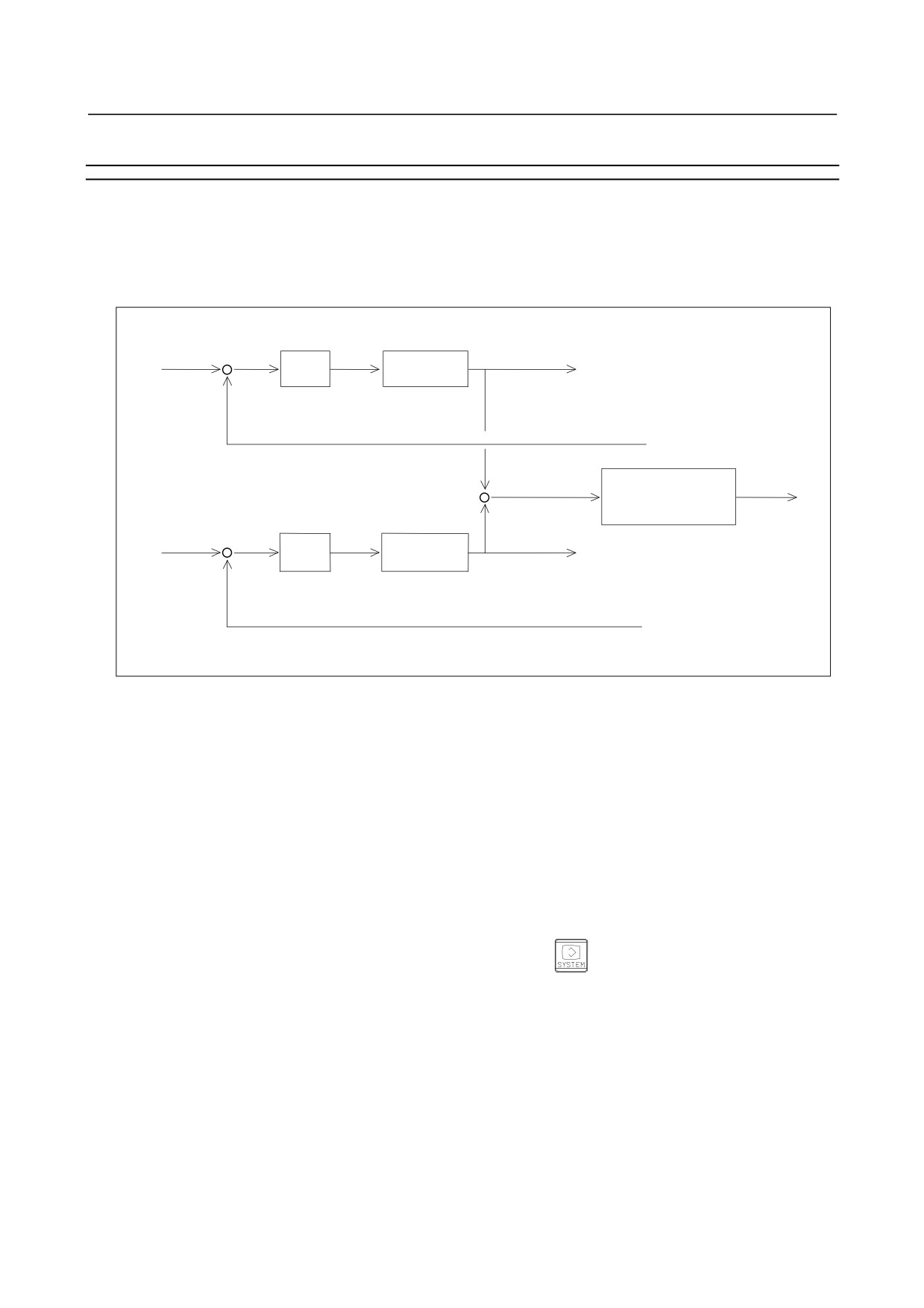
17.1.6 Axis Synchronous Control Torque Difference Alarm
Explanation
If a movement made along the master axis differs from a movement made along the slave axis during axis
synchronous control, the machine can be damaged. To prevent such damage, the torque command
difference between the two axes is observed. If the difference is abnormal, a servo alarm SV0420 can be
issued.
Position gain
Master axis
+
torque command
Feedrate
Kp
control
Master axis
-
position
command
Master axis
position feedback
Torque command
+
Compare absolute
difference
value with threshold
Alarm detection
Position gain
-
+
Feedrate
Kp
control
Slave axis torque
Slave axis
-
command
position
command
Slave axis
position feedback
Fig. 17.1.6 (a) System configuration
[Method of use]
Specify the threshold parameter No. 2031 according to the procedure below.
1.
Set 0 in parameter No. 2031, and disable the torque difference alarm detection function.
2.
To check the absolute value of the torque difference between the synchronous axes, set the
parameters below. Set the same value for the two axes placed under axis synchronous control.
Parameter No. 2115 = 0
Parameter No. 2151 is as described below.
• For the T series (2-path control system), set it to 434 if the setting of parameter No. 1023
is 1, 2, 5, 6, 9, 10… and to 6578 if it is 3, 4, 7, 8, 11, 12…
• For 1-path control system, set it to 434.
3.
Display the diagnostic screen by pressing the function key
then the [DGNOS] soft key.
Diagnose No. 0353 indicates the absolute value of the torque difference between the two axes.
4.
Read the absolute torque difference value presented when normal operation is being performed. In
the threshold parameter No. 2031, set a value obtained by adding some margin to the read absolute
value.
The absolute torque difference value can be observed with the Servo Guide.
-
Enabling/disabling of alarm detection
Alarm detection is enabled when the time set in parameter No. 8327 has elapsed after the servo ready
signal SA <F000.6> is set to 1. When the input signal NSYNCA <G059.7> is set to 1, alarm detection
is disabled.
- 275 -