FANUC Series 0i-MODEL D, Series 0i Mate-MODEL D. OPERATOR'S MANUAL - page 8

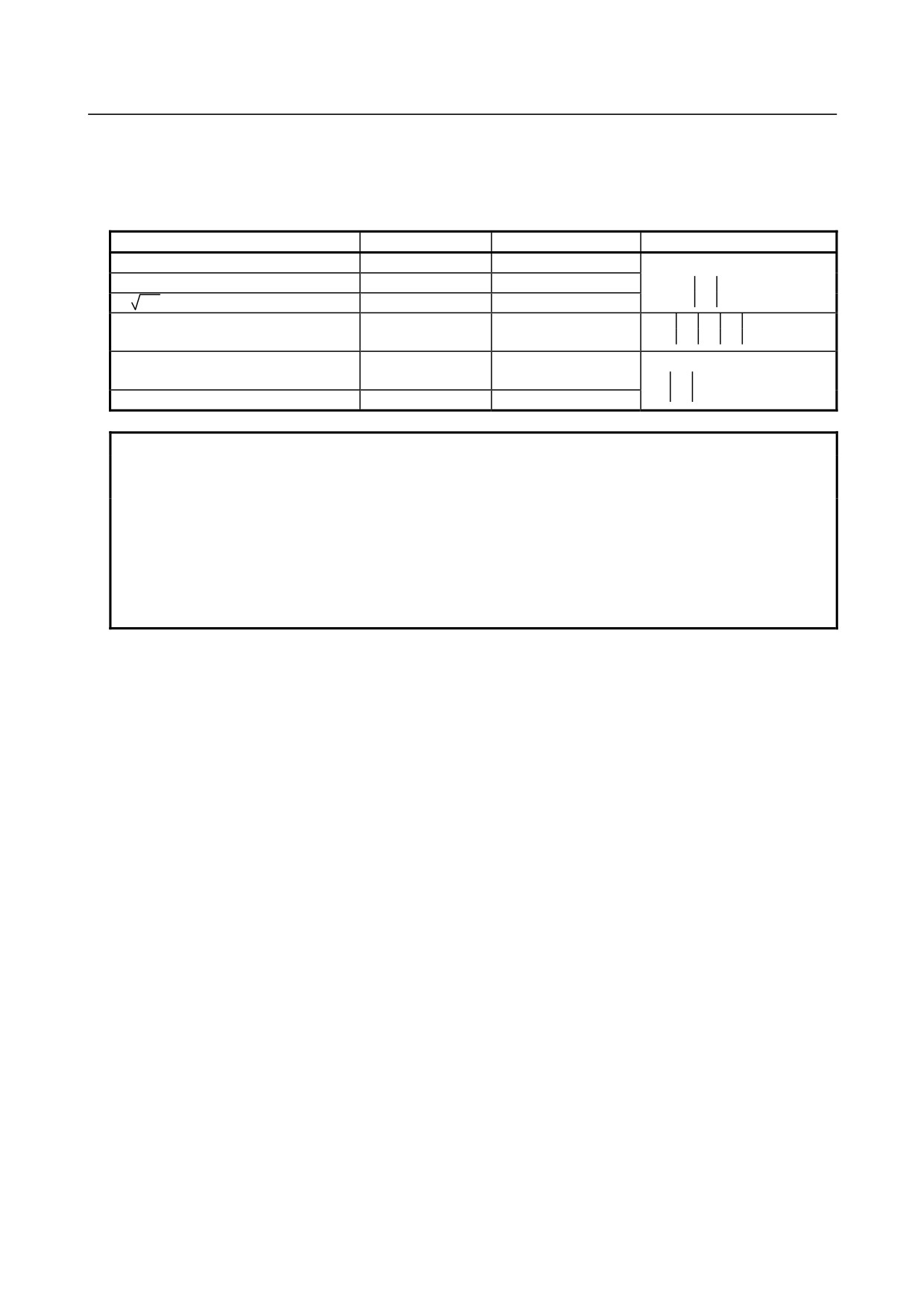
14.CUSTOM MACRO
PROGRAMMING
B-64304EN/02
Variable
Category
Variable name
Description
number
<1>
#4114
[#_BUFN]
Modal information
<2>
#4314
[#_ACTN]
(sequence number N)
<3>
#4514
[#_INTN]
<1>
#4115
[#_BUFO]
Modal information
<2>
#4315
[#_ACTO]
(program number O)
<3>
#4515
[#_INTO]
<1>
#4119
[#_BUFS]
<2>
#4319
[#_ACTS]
Modal information (S code)
<3>
#4519
[#_INTS]
<1>
#4120
[#_BUFT]
<2>
#4320
[#_ACTT]
Modal information (T code)
<3>
#4520
[#_INTT]
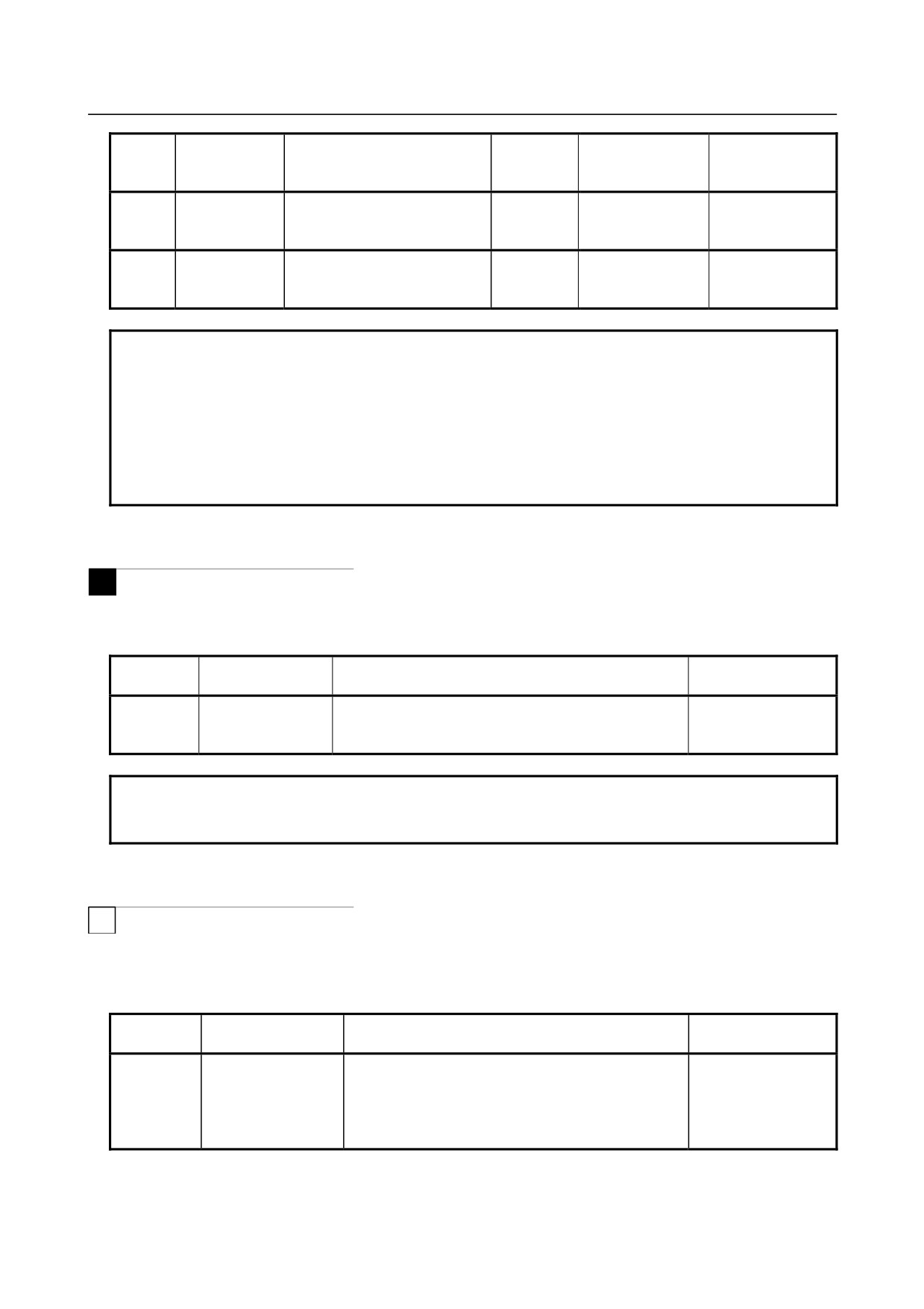
NOTE
Previous block and running block
Since the CNC reads the block that is ahead of the block currently being
executed by the machining program, the block being retrieved by the CNC is
normally different from that currently being executed. The previous block
indicates the block that is ahead of the block being retrieved by the CNC, that is,
the block that is ahead of the program block in which #4001 to #4130 are
specified.
[Example] O1234 ;
N10 G00 X200. Y200. ;
N20 G01 X1000. Y1000. F10. ;
:
:
N50 G00 X500. Y500. ;
N60 #1 = #4001 ;
Assume that the CNC is currently executing N20. If the CNC retrieved and processed the blocks up to N60 as
shown above, the running block is N20 and the previous block is N50. Therefore, group 1 modal information in the
running block is G01 and group 1 modal information in the previous block is G00.
When N60 #1 = #4201, #1 = 1.
When N60 #1 = #4001, #1 = 0.
-
Position information #5001-#5065 (Attribute: R)
The end position of the previous block, the specified current position (for the machine coordinate system
and workpiece coordinate system), and the skip signal position can be obtained by reading the values of
system variables #5001 to #5065.
Tool position/tool
Reading
Variable
Coordinate
Variable name
Position information
length/cutter
operation during
number
system
compensation
movement
#5001
[#_ABSIO[1]]
1st axis block end point position
Workpiece
:
:
:
coordinate
Not included
Enabled
#5005
[#_ABSIO[5]]
5th axis block end point position
system
#5021
[#_ABSMT[1]]
1st axis current position
Machine
:
:
:
coordinate
Included
Disabled
#5025
[#_ABSMT[5]]
5th axis current position
system
- 186 -
B-64304EN/02
PROGRAMMING
14.CUSTOM MACRO
Tool position/tool
Reading
Variable
Coordinate
Variable name
Position information
length/cutter
operation during
number
system
compensation
movement
#5041
[#_ABSOT[1]]
1st axis current position
Workpiece
:
:
:
coordinate
Included
Disabled
#5045
[#_ABSOT[5]]
5th axis current position
system
#5061
[#_ABSKP[1]]
1st axis skip position
Workpiece
:
:
:
coordinate
Included
Enabled
#5065
[#_ABSKP[5]]
5th axis skip position
system
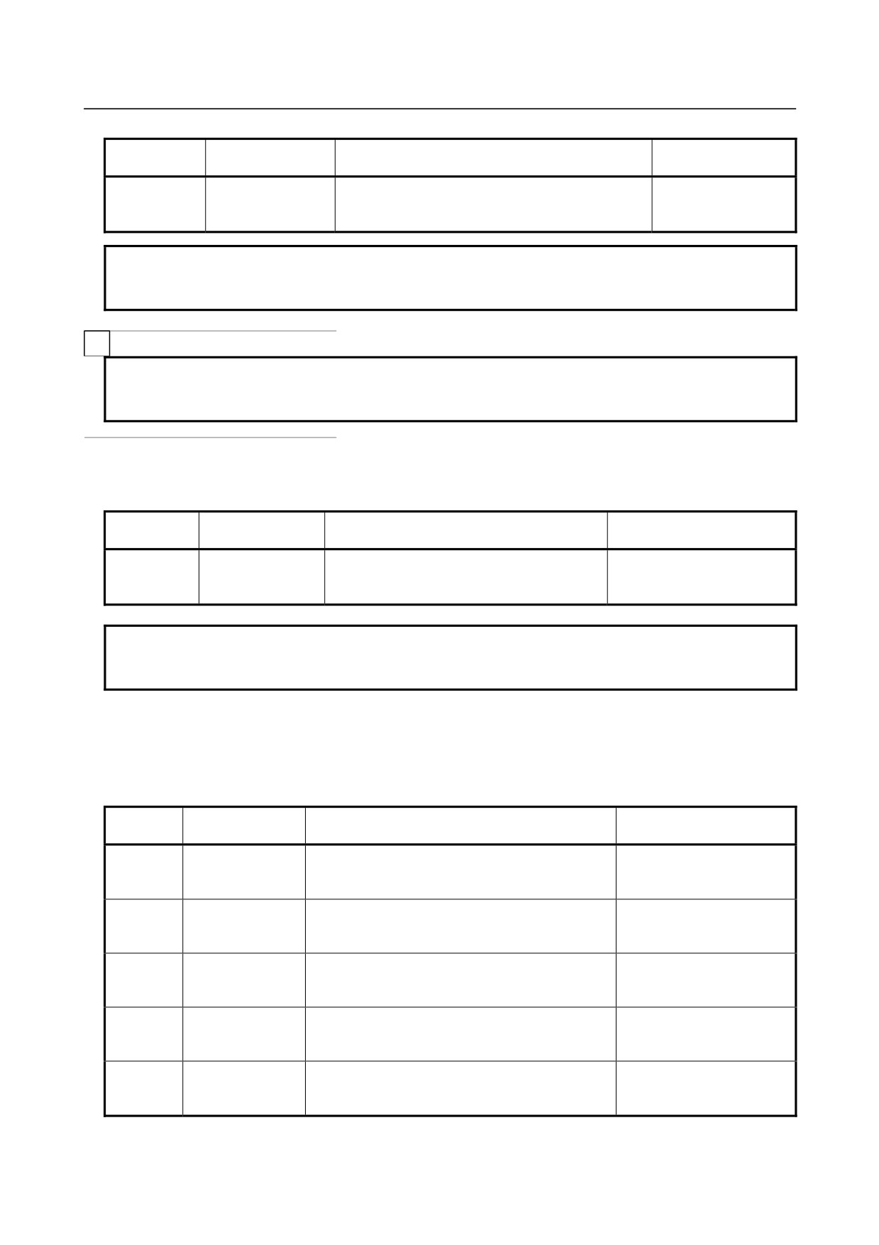
NOTE
1 When variables exceeding the number of control axes are specified, the alarm
PS0115, “VARIABLE NO. OUT OF RANGE” occurs.
2 The block end point position (ABSIO) of the skip (G31) is the position where the
skip signal is turned on. If the skip signal is not turned on, the position is the
end position of the block.
3 "Read operation during movement is disabled" means that the accurate reading
of values during movement is not guaranteed.
-
Tool length compensation value #5081#5085 (Attribute: R)
M
Tool length compensation in the block currently being executed can be obtained for each axis by reading
system variables #5081 to #5085.
Variable
Read operation
Variable name
Position information
number
during movement
#5081
[#_TOFS[1]]
1st axis tool length compensation value
:
:
:
Disabled
#5085
[#_TOFS[5]]
5th axis tool length compensation value
NOTE
When variables exceeding the number of control axes are specified, the alarm
PS0115, “VARIABLE NO. OUT OF RANGE” occurs.
-
Tool offset
#5081#5085, #5121-#5125 (Attribute: R)
T
Tool offset in the block currently being executed can be obtained for each axis by reading system
variables #5081 to #5085 or #5121 to #5125.
(X-axis: X-axis of basic three axes, Z-axis: Z-axis of basic
three axes, Y-axis: Y-axis of basic three axes)
<1> Without tool geometry/wear compensation memory (bit 6 (NGW) of parameter No.8136 = 1)
Variable
Read operation
Variable name
Position information
number
during movement
#5081
[#_TOFSWX]
X-axis tool offset value
#5082
[#_TOFSWZ]
Z-axis tool offset value
#5083
[#_TOFSWY]
Y-axis tool offset value
Disabled
#5084
[#_TOFS[4]]
4th axis tool offset value
#5085
[#_TOFS[5]]
5th axis tool offset value
- 187 -

14.CUSTOM MACRO
PROGRAMMING
B-64304EN/02
<2> With tool geometry/wear compensation memory (bit 6 (NGW) of parameter No.8136 = 0)
Variable
Read operation
Variable name
Position information
number
during movement
#5081
[#_TOFSWX]
X-axis tool offset value (wear)
#5082
[#_TOFSWZ]
Z-axis tool offset value (wear)
#5083
[#_TOFSWY]
Y-axis tool offset value (wear)
#5084
[#_TOFS[4]]
4th axis tool offset value (wear)
#5085
[#_TOFS[5]]
5th axis tool offset value (wear)
Disabled
#5121
[#_TOFSGX]
X-axis tool offset value (geometry)
#5122
[#_TOFSGZ]
Z-axis tool offset value (geometry)
#5123
[#_TOFSGY]
Y-axis tool offset value (geometry)
#5124
[#_TOFSG[4]]
4th axis tool offset value (geometry)
#5125
[#_TOFSG[5]]
5th axis tool offset value (geometry)
When the tool geometry/wear compensation memory is present (bit 6 (NGW) of parameter No. 8136 is 0),
the system variables depend on the settings of bit 2 (LWT) of parameter No. 5002 and bit 4 (LGT) of
parameter No. 5002, as shown below.
Variable
LWT=0
LWT=1
LWT=0
LWT=1
number
LGT=0
LGT=0
LGT=1
LGT=1
#5081
#5082
#5083
Wear compensation
0
Wear compensation
Wear compensation
#5084
#5085
#5121
#5122
Wear compensation +
#5123
Geometry compensation
Geometry compensation
Geometry compensation
Geometry compensation
#5124
#5125
NOTE
1 The set value is read as the tool offset regardless of bit 1 (ORC) of parameter
No.5004 and bit 0 (OWD) of parameter No.5040.
2 To read the tool offset (geometry) using #5121 to #5125, set bit 2 (VHD) of
parameter No.6004 to 0.
-
Servo position deviation #5101-#5105 (Attribute: R)
The servo position deviation for each axis can be obtained by reading system variables #5101 to #5105.
Variable
Read operation during
Variable name
Position information
number
movement
#5101
[#_SVERR[1]]
1st axis servo position deviation
:
:
:
Disabled
#5105
[#_SVERR[5]]
5th axis servo position deviation
NOTE
When variables exceeding the number of control axes are specified, the alarm
PS0115, “VARIABLE NO. OUT OF RANGE” occurs.
-
Manual handle interruption #5121-#5125 (Attribute: R)
The manual handle interruption for each axis can be obtained by reading system variables #5121 to
#5125.
- 188 -
B-64304EN/02
PROGRAMMING
14.CUSTOM MACRO
Variable
Read operation
Variable name
Position information
number
during movement
#5121
[#_MIRTP[1]]
1st axis manual handle interruption
:
:
:
Disabled
#5125
[#_MIRTP[5]]
5th axis manual handle interruption
NOTE
When variables exceeding the number of control axes are specified, the alarm
PS0115, “VARIABLE NO. OUT OF RANGE” occurs.
T
NOTE
#5121 to #5125 are enabled only when bit 2 (VHD) of parameter No.6004 is set
to 1.
-
Distance to go #5181-#5185 (Attribute: R)
The distance to go value for each axis can be obtained by reading system variables #5181 to #5185.
Variable
Read operation during
Variable name
Position information
number
movement
#5181
[#_DIST[1]]
1st axis distance to go value
:
:
:
Disabled
#5185
[#_DIST[5]]
5th axis distance to go value
NOTE
When variables exceeding the number of control axes are specified, the alarm
PS0115, “VARIABLE NO. OUT OF RANGE” occurs.
-
Workpiece origin offset value #5201-#5325 (Attribute: R/W)
The workpiece origin offset value can be obtained by reading system variables #5201 to #5325. The
offset value can also be changed by assigning values to the system variables.
Variable
Workpiece coordinate
Variable name
Controlled axis
number
system
#5201
[#_WZCMN[1]]
1st axis external workpiece origin offset value
External workpiece origin
:
:
:
offset value (applied to all
#5205
[#_WZCMN[5]]
5th axis external workpiece origin offset value
coordinate systems)
#5221
[#_WZG54[1]]
1st axis workpiece origin offset value
:
:
:
G54
#5225
[#_WZG54[5]]
5th axis workpiece origin offset value
#5241
[#_WZG55[1]]
1st axis workpiece origin offset value
:
:
:
G55
#5245
[#_WZG55[5]]
5th axis workpiece origin offset value
#5261
[#_WZG56[1]]
1st axis workpiece origin offset value
:
:
:
G56
#5265
[#_WZG56[5]]
5th axis workpiece origin offset value
#5281
[#_WZG57[1]]
1st axis workpiece origin offset value
:
:
:
G57
#5285
[#_WZG57[5]]
5th axis workpiece origin offset value
- 189 -

14.CUSTOM MACRO
PROGRAMMING
B-64304EN/02
Variable
Workpiece coordinate
Variable name
Controlled axis
number
system
#5301
[#_WZG58[1]]
1st axis workpiece origin offset value
:
:
:
G58
#5305
[#_WZG58[5]]
5th axis workpiece origin offset value
#5321
[#_WZG59[1]]
1st axis workpiece origin offset value
:
:
:
G59
#5325
[#_WZG59[5]]
5th axis workpiece origin offset value
M
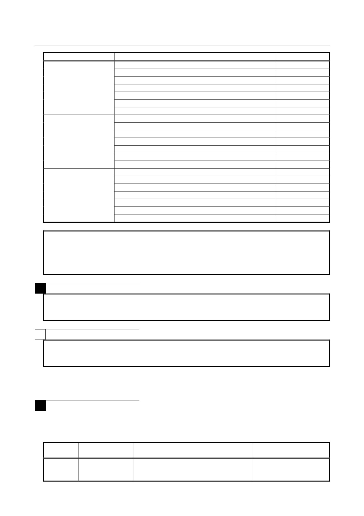
The following variables can also be used when bit 5 (D15) of parameter No. 6004 is set to 0:
Axis
Function
Variable number
1st axis
External workpiece origin offset value
#2500
G54 workpiece origin offset value
#2501
G55 workpiece origin offset value
#2502
G56 workpiece origin offset value
#2503
G57 workpiece origin offset value
#2504
G58 workpiece origin offset value
#2505
G59 workpiece origin offset value
#2506
2nd axis
External workpiece origin offset value
#2600
G54 workpiece origin offset value
#2601
G55 workpiece origin offset value
#2602
G56 workpiece origin offset value
#2603
G57 workpiece origin offset value
#2604
G58 workpiece origin offset value
#2605
G59 workpiece origin offset value
#2606
3rd axis
External workpiece origin offset value
#2700
G54 workpiece origin offset value
#2701
G55 workpiece origin offset value
#2702
G56 workpiece origin offset value
#2703
G57 workpiece origin offset value
#2704
G58 workpiece origin offset value
#2705
G59 workpiece origin offset value
#2706
4th axis
External workpiece origin offset value
#2800
G54 workpiece origin offset value
#2801
G55 workpiece origin offset value
#2802
G56 workpiece origin offset value
#2803
G57 workpiece origin offset value
#2804
G58 workpiece origin offset value
#2805
G59 workpiece origin offset value
#2806
T
The following variables can be used to maintain compatibility with conventional models.
Axis
Function
Variable number
1st axis
External workpiece origin offset value
#2550
G54 workpiece origin offset value
#2551
G55 workpiece origin offset value
#2552
G56 workpiece origin offset value
#2553
G57 workpiece origin offset value
#2554
G58 workpiece origin offset value
#2555
G59 workpiece origin offset value
#2556
- 190 -
B-64304EN/02
PROGRAMMING
14.CUSTOM MACRO
Axis
Function
Variable number
2nd axis
External workpiece origin offset value
#2650
G54 workpiece origin offset value
#2651
G55 workpiece origin offset value
#2652
G56 workpiece origin offset value
#2653
G57 workpiece origin offset value
#2654
G58 workpiece origin offset value
#2655
G59 workpiece origin offset value
#2656
3rd axis
External workpiece origin offset value
#2750
G54 workpiece origin offset value
#2751
G55 workpiece origin offset value
#2752
G56 workpiece origin offset value
#2753
G57 workpiece origin offset value
#2754
G58 workpiece origin offset value
#2755
G59 workpiece origin offset value
#2756
4th axis
External workpiece origin offset value
#2850
G54 workpiece origin offset value
#2851
G55 workpiece origin offset value
#2852
G56 workpiece origin offset value
#2853
G57 workpiece origin offset value
#2854
G58 workpiece origin offset value
#2855
G59 workpiece origin offset value
#2856
NOTE
1 When variables exceeding the number of control axes are specified, the alarm
PS0115, “VARIABLE NO. OUT OF RANGE” occurs.
2 For the workpiece origin offset values for up to the number (5) of control axes,
variables #5201 to #5325 can also be used.
M
NOTE
To use variables #2500 to #2806 and #5201 to #5325, enable the workpiece
coordinate system (bit 0 (NWZ) of parameter No. 8136 is 0).
T
NOTE
To use variables #2550 to #2856 and #5201 to #5325, enable the workpiece
coordinate system (bit 0 (NWZ) of parameter No. 8136 is 0).
-
Workpiece origin offset value of the additional workpiece coordinate system
#7001-#7945, #14001-#14945 (Attribute: R/W)
M
The workpiece origin offset value of the additional workpiece coordinate system can be obtained by
reading system variables #7001 to #7945, #14001 to #14945. The offset value can also be changed by
assigning values to the system variables.
Variable
Additional workpiece
Variable name
Controlled axis
number
system number
#7001
[#_WZP1[1]]
1st axis workpiece origin offset value
1
:
:
:
(G54.1 P1)
#7005
[#_WZP1[5]]
5th axis workpiece origin offset value
- 191 -

14.CUSTOM MACRO
PROGRAMMING
B-64304EN/02
Variable
Additional workpiece
Variable name
Controlled axis
number
system number
#7021
[#_WZP2[1]]
1st axis workpiece origin offset value
2
:
:
:
(G54.1 P2)
#7025
[#_WZP2[5]]
5th axis workpiece origin offset value
:
:
:
:
#7941
[#_WZP48[1]]
1st axis workpiece origin offset value
48
:
:
:
(G54.1 P48)
#7945
[#_WZP48[5]]
5th axis workpiece origin offset value
System variable number = 7000 + (Coordinate system number -1) × 20 + Axis number
Coordinate number: 1 to 48
Axis number:
1 to 5
Variable
Additional workpiece
Variable name
Controlled axis
number
system number
#14001
[#_WZP1[1]]
1st axis workpiece origin offset value
1
:
:
:
(G54.1 P1)
#14005
[#_WZP1[5]]
5th axis workpiece origin offset value
#14021
[#_WZP2[1]]
1st axis workpiece origin offset value
2
:
:
:
(G54.1 P2)
#14025
[#_WZP2[5]]
5th axis workpiece origin offset value
:
:
:
:
#14941
[#_WZP48[1]]
1st axis workpiece origin offset value
48
:
:
:
(G54.1 P48)
#14945
[#_WZP48[5]]
5th axis workpiece origin offset value
System variable number = 14000 + (Coordinate system number -1) × 20 + Axis number
Coordinate number: 1 to 48
Axis number:
1 to 5
NOTE
1 When variables exceeding the number of control axes are specified, the alarm
PS0115, “VARIABLE NO. OUT OF RANGE” occurs.
2 To use variables #7001 to #7945 and #14001 to #14945 (G54.1 P1 to G54.1
P48), enable the addition of workpiece coordinate system pairs (48 pairs) (bit 2
(NWN) of parameter No. 8136 is 0).
-
Switching between P-CODE variables and system variables (#10000 or later)
#8570 (Attribute: R/W)
This system variable allows read/write operations of P-CODE variables (#10000 to #89999) for the macro
executor function. For details on P-CODE variables, refer to the Macro Compiler / Macro Executor
Programming Manual (B-64303EN-2).
System variable #8570 can be used to make variables #10000 or later correspond to either P-CODE
variables or system variables.
#8570 setting
Specified variable
Corresponding variable
#10000
System variables (#10000)
#8570 = 0
:
:
#89999
System variables (#89999)
- 192 -

B-64304EN/02
PROGRAMMING
14.CUSTOM MACRO
#8570 setting
Specified variable
Corresponding variable
#10000
P-CODE variables (#10000)
#8570 = 1
:
:
#89999
P-CODE variables (#89999)
Example
#8570 = 0 ;
#10001 = 123 ; → Writing to system variable #10001 (tool compensation)
#8570 = 1 ;
#10001 = 456 ; → Writing to P-CODE variable #10001 (tool compensation)
NOTE
1 Variable #8570 can be used only when the macro executor function is enabled.
2 System variables (#10000 or later) always correspond to system variables
specified by their variable names even when #8570 is 1.
3 When an attempt is made to access a variable that cannot be used with
P-CODE variables (#10000 or later), an alarm PS0115 occurs.
14.3 ARITHMETIC AND LOGIC OPERATION
Various operations can be performed on variables. Program an arithmetic and logic operation in the same
way as for a general arithmetic expression.
#i=<expression>
<Expression>
The expression to the right of the arithmetic and logic operation contains constants and/or variables
combined by a function or operator. Variables #j and #k below can be replaced with a constant. If a
constant used in an expression has no decimal point, it is assumed to end with a decimal point.
Table 14.3 (a) Arithmetic and logic operation
Type of operation
Operation
Description
<1> Definition or
#i=#j
Definition or replacement of a variable
replacement
<2> Addition-type
#i=#j+#k
Addition
operations
#i=#j-#k
Subtraction
#i=#j OR #k
Logical OR (bit by bit of 32 bits)
#i=#j XOR #k
Exclusive OR (bit by bit of 32 bits)
<3> Multiplication-type
#i=#j*#k
Multiplication
operations
#i=#j/#k
Division
#i=#j AND #k
Logical AND (bit by bit of 32 bits)
#i=#j MOD #k
Remainder (A remainder is obtained after #j and #k are
rounded to their nearest whole numbers. When #j is a
negative value, #i is assumed to be a negative value.)
- 193 -

14.CUSTOM MACRO
PROGRAMMING
B-64304EN/02
Type of operation
Operation
Description
<4> Functions
#i=SIN[#j]
Sine (in degrees)
#i=COS[#j]
Cosine (in degrees)
#i=TAN[#j]
Tangent (in degrees)
#i=ASIN[#j]
Arc sine
#i=ACOS[#j]
Arc cosine
#i=ATAN[#j]
Arc tangent (one argument), ATN can also be used.
#i=ATAN[#j]/[#k]
Arc tangent (two arguments), ATN can also be used.
#i=ATAN[#j,#k]
Arc tangent (two arguments), ATN can also be used.
#i=SQRT[#j]
Square root, SQR can also be used.
#i=ABS[#j]
Absolute value
#i=BIN[#j]
Conversion from BCD to binary
#i=BCD[#j]
Conversion from binary to BCD
#i=ROUND[#j]
Rounding off, RND can also be used.
#i=FIX[#j]
Rounding down to an integer
#i=FUP[#j]
Rounding up to an integer
#i=LN[#j]
Natural logarithm
#i=EXP[#j]
Exponent using base e (2.718...)
#i=POW[#j,#k]
Power (#j to the #kth power)
#i=ADP[#j]
Addition of a decimal point
Explanation
-
Angle units
The units of angles used with the SIN, COS, ASIN, ACOS, TAN, and ATAN functions are degrees.
For
example, 90 degrees and 30 minutes is represented as 90.5 degrees.
-
ARCSIN #i = ASIN[#j];
•
The solution ranges are as indicated below:
When the bit 0 (NAT) of parameter No.6004 is set to 0: 270° to 90°
When the bit 0 (NAT) of parameter No.6004 is set to 1: -90° to 90°
•
When #j is beyond the range of -1 to 1, an alarm PS0119 is issued.
•
A constant can be used instead of the #j variable.
-
ARCCOS #i = ACOS[#j];
•
The solution ranges from 180° to 0°.
•
When #j is beyond the range of -1 to 1, an alarm PS0119 is issued.
•
A constant can be used instead of the #j variable.
-
ARCTAN #i = ATAN[#j]/[#k]; (two arguments)
•
ATAN[#j,#k] is equivalent to ATAN[#j]/[#k].
•
When point (#k,#j) on plane X-Y is given, this function returns the value of the arc tangent for the
angle made by the point.
•
A constant can be used instead of the #j variable.
•
The solution ranges are as follows:
When the bit 0 (NAT) of parameter No.6004 is set to 0: 0° to 360°
Example:
When #1 = ATAN[-1]/[-1]; is specified, #1 is 225.0.
When the bit 0 (NAT) of parameter No.6004 is set to 1: -180° to 180°
Example:
When #1 = ATAN[-1]/[-1]; is specified, #1 is -135.0.
- 194 -
B-64304EN/02
PROGRAMMING
14.CUSTOM MACRO
-
ARCTAN #i = ATAN[#j]; (one argument)
•
When ATAN is specified with one argument, this function returns the main value of arc tangent
(-90° ≤ ATAN[#j] ≤ 90°). In other word, this function returns the same value as ATAN in
calculator specifications.
•
To use this function as the dividend of a division, be sure to enclose it with brackets ([ ]). If this
function is not enclosed, ATAN[#j]/[#k] is assumed.
Example:
#100 = [ATAN[1]]/10 ; : Divides ATAN with one argument by 10.
#100 = ATAN[1]/[10] ; : Executes ATAN with two arguments.
#100 = ATAN[1]/10 ;
: Assumes ATAN with two arguments, but issues an alarm PS1131 because the X
coordinate specification is not enclosed with brackets ([ ]).
-
Natural logarithm #i = LN[#j];
•
When the antilogarithm (#j) is zero or smaller, an alarm PS0119 is issued.
•
A constant can be used instead of the #j variable.
-
Exponential function #i = EXP[#j];
•
When the result of the operation overflows, an alarm PS0119 is issued.
•
A constant can be used instead of the #j variable.
-
ROUND function
•
When the ROUND function is included in an arithmetic or logic operation command, IF statement,
or WHILE statement, the ROUND function rounds off at the first decimal place.
Example:
When #1=ROUND[#2]; is executed where #2 holds 1.2345, the value of variable #1 is 1.0.
•
When the ROUND function is used in NC statement addresses, the ROUND function rounds off the
specified value according to the least input increment of the address.
Example:
Creation of a drilling program that cuts according to the values of variables #1 and #2, then returns to the
original position
Suppose that the increment system is 1/1000 mm, variable #1 holds 1.2345, and variable #2 holds 2.3456.
Then,
G00 G91 X-#1 ; Moves 1.235 mm in negative direction.
G01 X-#2 F300 ; Moves 2.346 mm in negative direction.
G00 X[#1+#2] ; Since 1.2345 + 2.3456 = 3.5801 in positive direction, the travel distance is 3.580, which
does not return the tool to the original position.
This difference comes from whether addition is performed before or after rounding off.
G00X-[ROUND[#1]+ROUND[#2]] ; must be specified to return the tool to the original position.
-
Add decimal point (ADP) function
•
ADP[#n] (n = 1 to 33) can be executed to add a decimal point to an argument passed with no
decimal point, in the subprogram.
Example:
In the subprogram called with G65 P_X10;, the value of ADP[#24] is a value to which a decimal point is
added at its end (that is, 10.). Use this function when you do not want to consider the increment system in
the subprogram. When bit 4 (CVA) of parameter No. 6007 is set to 1, however, the ADP function cannot
be used because any argument is converted to 0.01 the moment it is passed.
NOTE
For compatibility among programs, it is recommended that the ADP function be
not used, and decimal points be added in the argument specification for a macro
call.
- 195 -
14.CUSTOM MACRO
PROGRAMMING
B-64304EN/02
-
Rounding up and down to an integer (FUP and FIX)
With CNC, when the absolute value of the integer produced by an operation on a number is greater than
the absolute value of the original number, such an operation is referred to as rounding up to an integer.
Conversely, when the absolute value of the integer produced by an operation on a number is less than the
absolute value of the original number, such an operation is referred to as rounding down to an integer.
Be particularly careful when handling negative numbers.
Example:
Suppose that #1=1.2 and #2=-1.2.
When #3=FUP[#1] ; is executed, 2.0 is assigned to #3.
When #3=FIX[#1] ; is executed, 1.0 is assigned to #3.
When #3=FUP[#2] ; is executed, -2.0 is assigned to #3.
When #3=FIX[#2] ; is executed, -1.0 is assigned to #3.
-
Abbreviations of arithmetic and logic operation commands
When a function is specified in a program, the first two characters of the function name can be used to
specify the function.
Example:
ROUND → RO
FIX → FI
NOTE
1 POW cannot be abbreviated.
2 When an operation command is entered in an abbreviated form, the abbreviated
form is displayed as is.
For example, when "RO" is entered, "RO" is displayed as is without being
converted to "ROUND".
-
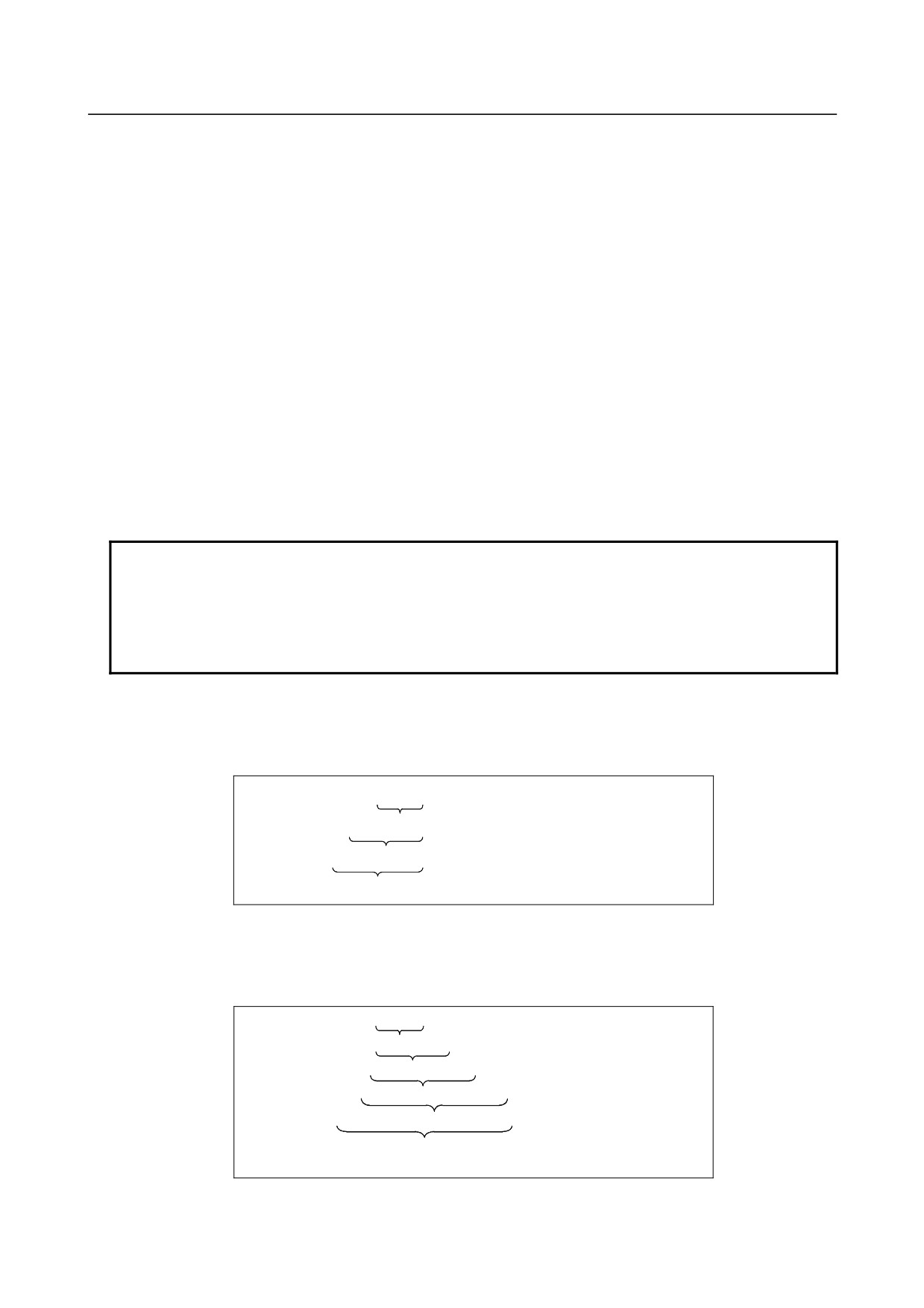
Priority of operations
<1> Functions
<2> Operations such as multiplication and division (*, /, AND)
<3> Operations such as addition and subtraction (+, -, OR, XOR)
Example) #1=#2+#3*SIN[#4];
<1>
<2>
<1>, <2> and <3> indicate the order of
<3>
operations.
-
Bracket nesting
Brackets are used to change the order of operations. Brackets can be used to a depth of five levels
including the brackets used to enclose a function. When a depth of five levels is exceeded, an alarm
PS0118 occurs.
Example) #1=SIN [ [ [#2+#3] *#4 +#5] *#6];
<1>
<2>
<3>
<4>
<5>
<1> to <5> indicate the order of operations.
- 196 -
B-64304EN/02
PROGRAMMING
14.CUSTOM MACRO
Limitation
•
Caution concerning decreased precision
When bit 0 (F0C) of parameter No. 6008 is set to 0
•
Addition and subtraction
Note that when an absolute value is subtracted from another absolute value in addition or subtraction,
the relative error may become 10-15 or greater.
For example, assume that #1 and #2 have the following true values in the process of operation.
(The following values are examples in the process of operation and cannot actually be specified from
any program.)
#1=9876543210.987654321
#2=9876543210.987657777
You cannot obtain the following result with operation #2-#1:
#2-#1=0.000003456
This is because the precision of custom macro variables is 15 decimal digits. With this precision,
the values of #1 and #2 become:
#1=9876543210.987650000
#2=9876543210.987660000
(Precisely, the actual values are slightly different from the above values because they are internally
processed in binary.) Therefore, the result is:
#2-#1=0.000010000
A large error occurs.
•
Logical expressions
Be aware of errors that can result from conditional expressions using EQ, NE, GT, LT, GE, and LE
because they are processed basically in the same way as addition and subtraction. For example, if
the following statement is used to decide whether #1 is equal to #2 in the above example, a correct
decision may not be resulted because errors may occur:
IF [#1 EQ #2]
Evaluate the difference between #1 and #2 with:
IF [ABS [#1-#2]LT 0.1]
Then, assume that the values are equal when the difference does not exceed the allowable error
range.
•
Trigonometric functions
The absolute error is guaranteed for trigonometric functions. However, the relative error is 10-15 or
greater. Carefully perform multiplication or division after executing a trigonometric function.
•
FIX function
When using the FIX function for the result of an operation, be careful with the precision. For
example, when the following operations are performed, the value of #3 may not always be 2.
N10 #1=0.002;
N20 #2=#1*1000;
N30 #3=FIX[#2];
This is because an error may occur in operation N20 and the result may not be
#2=2.0000000000000000
but a value a little smaller than 2 such as the following:
#2=1.9999999999999997
To prevent this, specify N30 as follows:
N30 #3=FIX[#2+0.001];
Generally, specify the FIX function as follows:
FIX[expression] → FIX[expression ±ε]
(Specify +ε when the value of the expression is positive or -ε when it is negative, and 0.1, 0.01,
0.001, ... for ε as required.)
NOTE
The operation result of exponential function
#i=EXP[#j]; overflows when
#j
exceeds about 790.
- 197 -
14.CUSTOM MACRO
PROGRAMMING
B-64304EN/02
When bit 0 (F0C) of parameter No. 6008 is set to 1
Errors may occur when operations are performed.
Table 14.3 (b) Errors involved in operations
Operation
Average error
Maximum error
Type of error
a = b*c
1.55×10⁻¹⁰
4.66×10⁻¹⁰
Relative error
a = b / c
4.66×10⁻¹⁰
1.88×10⁻⁹
ε
a
a = b
1.24×10⁻⁹
3.73×10⁻⁹
a = b + c
2.33×10⁻¹⁰
5.32×10⁻¹⁰
ε
ε
MIN
b
,
c
a = b - c
a = SIN [ b ]
5.0×10⁻⁹
1.0×10⁻⁸
Absolute error
a = COS [ b ]
degrees
ε
a = ATAN [ b ] / [ c ]
1.8×10⁻⁶
3.6×10⁻⁶
NOTE
1 The relative error depends on the result of the operation.
2 Smaller of the two types of errors is used.
3 The absolute error is constant, regardless of the result of the operation.
4 Function TAN performs SIN/COS.
5 Note that, in the case of natural logarithm #i=LN[#j]; and exponential function
#i=EXP[#j];, the relative error may become 10-8 or greater.
6 The operation result of exponential function
#i=EXP[#j]; overflows when
#j
exceeds about 110.
•
The precision of variable values is about 8 decimal digits. When very large numbers are handled in
an addition or subtraction, the expected results may not be obtained.
Example:
When an attempt is made to assign the following values to variables #1 and #2:
#1=9876543210123.456
#2=9876543277777.777
the values of the variables become:
#1=9876543200000.000
#2=9876543300000.000
In this case, when #3=#2-#1; is calculated, #3=100000.000 results.
(The actual result of this calculation is
slightly different because it is performed in binary.)
•
Also be aware of errors that can result from conditional expressions using EQ, NE, GE, GT, LE, and
LT.
Example:
IF[#1 EQ #2] is effected by errors in both #1 and #2, possibly resulting in an incorrect decision.
Therefore, instead find the difference between the two variables with IF[ABS[#1-#2]LT0.001].
Then, assume that the values of the two variables are equal when the difference does not exceed an
allowable limit (0.001 in this case).
•
Also, be careful when rounding down a value.
Example:
When #2=#1*1000; is calculated where #1=0.002;, the resulting value of variable #2 is not exactly 2 but
1.99999997.
Here, when #3=FIX[#2]; is specified, the resulting value of variable #3 is not 2.0 but 1.0.
In this case, round down the value after correcting the error so that the result is greater than the expected
number, or round it off as follows:
#3=FIX[#2+0.001]
#3=ROUND[#2]
- 198 -
B-64304EN/02
PROGRAMMING
14.CUSTOM MACRO
-
Brackets
Brackets ([ ]) are used to enclose an expression.
Note that parentheses ( ) are used for comments.
-
Divisor
When a divisor of zero is specified in a division, an alarm PS0112 occurs.
- 199 -

14.CUSTOM MACRO
PROGRAMMING
B-64304EN/02
14.4 READING PARAMETERS
Overview
By using the PRM function, it is possible to read parameters.
Format
Remarks
#i = PRM[ #j, #k ] ;
In the case of parameters other than axis type parameters
#i = PRM[ #j, #k ] / [ #l ] ;
In the case of axis type parameters
Explanation
-
Reading a parameter
#i=PRM[#j,#k]
#i=PRM[#j,#k]/[#l]
• For #j, enter a parameter number. If the number of a parameter that cannot be read, alarm PS0119,
"ARGUMENT VALUE OUT OF RANGE", is issued.
• To read a bit type parameter, specify, for #k, the bit number of the bit type parameter in the range of
0 to 7. If a bit number is specified, data with the specified bit is read. If none is specified, data with
all bits is read. For parameters other than bit type parameters, the bit number is ignored.
• For #l, set the axis number of an axis type parameter in the range of 1 to 5. If an axis type parameter
is to be read but #l is not specified, alarm PS0119 is issued. For parameters other than axis type
parameters, #1 may be omitted together with '/'.
Example
1.
Reading the value of the third axis of bit 0 (MIR) of bit axis type parameter No. 0012
If parameter No. 0012 (third axis) = 10000001
#2=12 ;
Parameter number setting
#3=0 ;
Bit number setting
#4=3 ;
Axis number setting
If reading data with all bits
#1=PRM[#2]/[#4] ;
#1=10000001
If reading data with a specified bit
#1=PRM[#2, #3]/[#4] ;
#1=1
2.
Reading the value of the fourth axis of axis type parameter No. 1322
#2=1322 ;
Parameter number setting
#4=4 ;
Axis number setting
#1=PRM[#2]/[#4] ;
3.
Reading bit 2 (SBP) of bit type parameter No. 3404
If parameter No. 3404 = 10010000
#2=3404 ;
Parameter number setting
#3=2 ;
Bit number setting
If reading data with all bits
#1=PRM[#2] ;
#1=10010000
If reading data with a specified bit
#1=PRM[#2,#3] ;
#1=0
- 200 -

B-64304EN/02
PROGRAMMING
14.CUSTOM MACRO
14.5 MACRO STATEMENTS AND NC STATEMENTS
The following blocks are referred to as macro statements:
• Blocks containing an arithmetic or logic operation (=)
• Blocks containing a control statement (such as GOTO, DO, END)
• Blocks containing a macro call command (such as macro calls by G65, G66, G67, or other G codes,
or by M codes)
Any block other than a macro statement is referred to as an NC statement.
Explanation
-
Differences from NC statements
• Even when single block mode is on, the machine does not stop. Note, however, that the machine
stops in the single block mode when bit 5 of parameter SBM No. 6000 is 1.
M
• Macro blocks are not regarded as blocks that involve no movement in the cutter compensation mode.
-
NC statements that have the same property as macro statements
• An NC statement has the same property as a macro statement when the NC statement is a
subprogram call command (subprogram call by an M98, M code or subprogram call by a T code)
and is also a block that does not include any command address other than O, N, P, and L.
• An NC statement has the same property as a macro statement when the NC statement is an M99
command and is also a block that does not include any command address other than O, N, P, and L.
14.6 BRANCH AND REPETITION
In a program, the flow of control can be changed using the GOTO statement and IF statement. Three
types of branch and repetition operations are used:
Branch and
GOTO
(unconditional branch)
repetition
IF
(conditional branch: if ..., then...)
WHILE
(repetition while ...)
14.6.1 Unconditional Branch (GOTO Statement)
A branch to sequence number n occurs. When a sequence number outside of the range 1 to 99999 is
specified, an alarm PS1128 occurs. A sequence number can also be specified using an expression.
GOTOn ; n: Sequence number (1 to 99999)
Example:
GOTO 1;
GOTO #10;
WARNING
Do not specify multiple blocks with the same sequence number in a single
program. It is very dangerous to specify such blocks because the destination of
a branch from the GOTO statement is undefined.
- 201 -
14.CUSTOM MACRO
PROGRAMMING
B-64304EN/02
NOTE
1 A backward branch takes more time as compared with a forward branch.
2 In the block with sequence number n, which is the branch destination of the
GOTO n command, sequence number n must be located at the beginning of the
block. Otherwise, the branch cannot be executed.
14.6.2 GOTO Statement Using Stored Sequence Numbers
When the GOTO statement is executed in a custom macro control command, a sequence number search is
made for sequence numbers stored at previous execution of the corresponding blocks at a high speed.
Sequence numbers stored at previous execution indicate the sequence numbers for a subprogram call and
the sequence numbers that are unique in the same program of the sequence numbers at previous execution,
and the CNC records these sequence numbers.
The storage type differs depending on the values of the following parameters.
(1) When bit 1 (MGO) of parameter No. 6000 is set to 1
•
Fixed type:
Up to 20 sequence numbers stored at execution of the corresponding blocks
from the start of operation
(2) When bit 4 (HGO) of parameter No. 6000 is set to 1
•
Variable type: Up to 30 sequence numbers stored at execution of the corresponding blocks
before execution of the GOTO statement
•
History type: Up to 10 sequence numbers stored by a sequence number search previously
made using the GOTO statement
The stored sequence numbers are canceled in the following cases:
•
Immediately after power-on
•
After a reset
•
Operation after program registration or editing (including background editing and MDI program
editing)
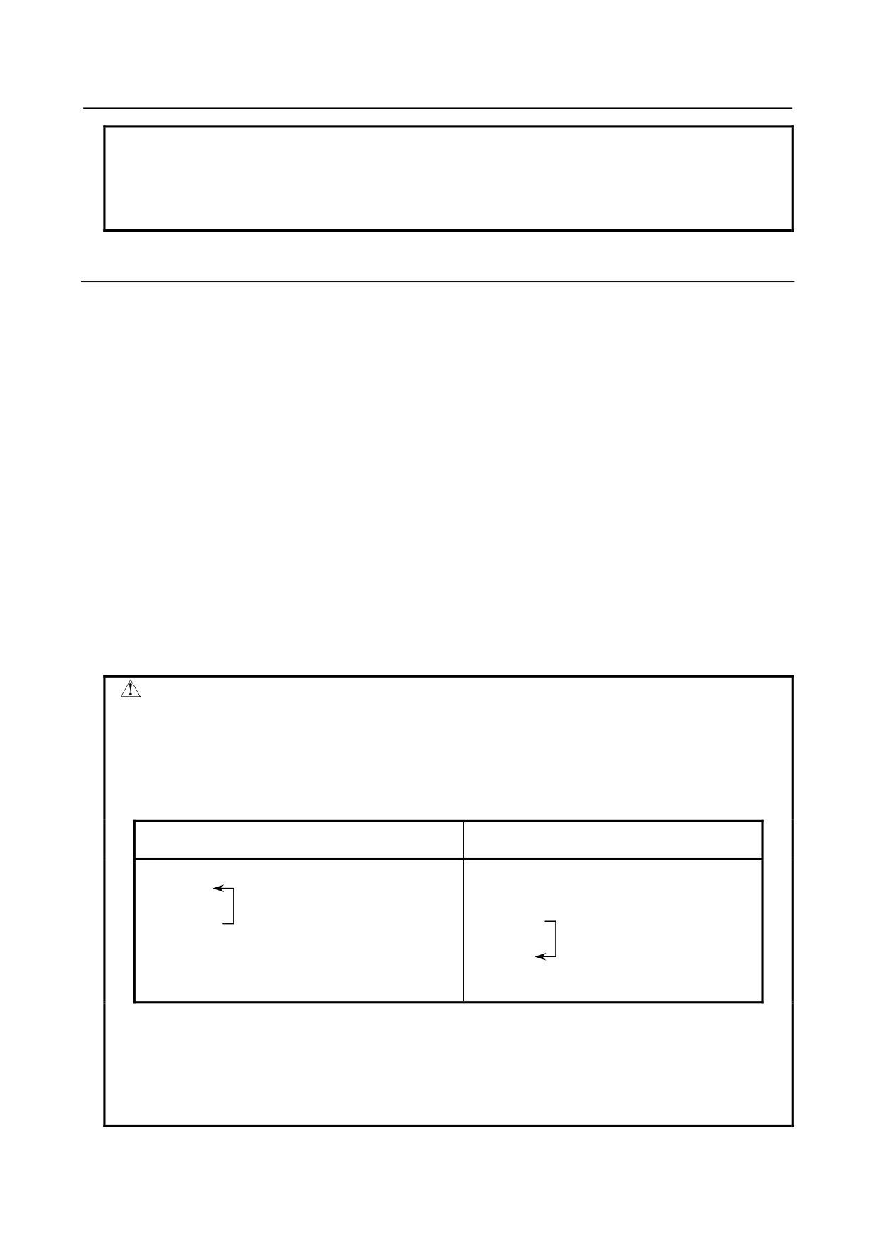
WARNING
Do not specify multiple blocks with the same sequence number in a single
program.
It is very dangerous to specify the sequence number of the branch destination
before and after the GOTO statement and execute the GOTO statement
because the branch destination changes according to the values of the
parameters as shown below:
When bit 1 (MGO) or 4 (HGO) of parameter No.
When both bits 1 (MGO) and 4 (HGO) of
6000 is set to 1
parameter No. 6000 are set to 0
:
:
A branch to
N10;
N10;
N10 before
:
:
A branch to
the GOTO
GOTO10;
GOTO10;
N10 after the
statement
:
:
GOTO
occurs.
N10;
N10;
statement
occurs.
When bit 1 (MGO) or 4 (HGO) of parameter No. 6000 is set to 1 and the GOTO
statement is executed, the sequence number of the branch destination may not
be contained in the sequence numbers stored at previous execution of the
corresponding blocks. In this case, a branch to the sequence number in a block
following the GOTO statement occurs (the destination is the same as when both
bits are set to 0).
- 202 -
B-64304EN/02
PROGRAMMING
14.CUSTOM MACRO
NOTE
When an external program is read and executed by DNC operation, the
executed sequence numbers are not stored.
When a program registered in memory is executed by a subprogram call, the
sequence numbers are stored.
CAUTION
According to the restrictions on the GOTO statement, no branch to a sequence
number within a DO-END loop cannot be made. If a program in which a branch
to a sequence number within a loop occurs is executed, operation may differ
depending on whether the GOTO statement using stored sequence numbers is
used.
14.6.3 Conditional Branch (IF Statement)
Specify a <conditional expression> after IF.
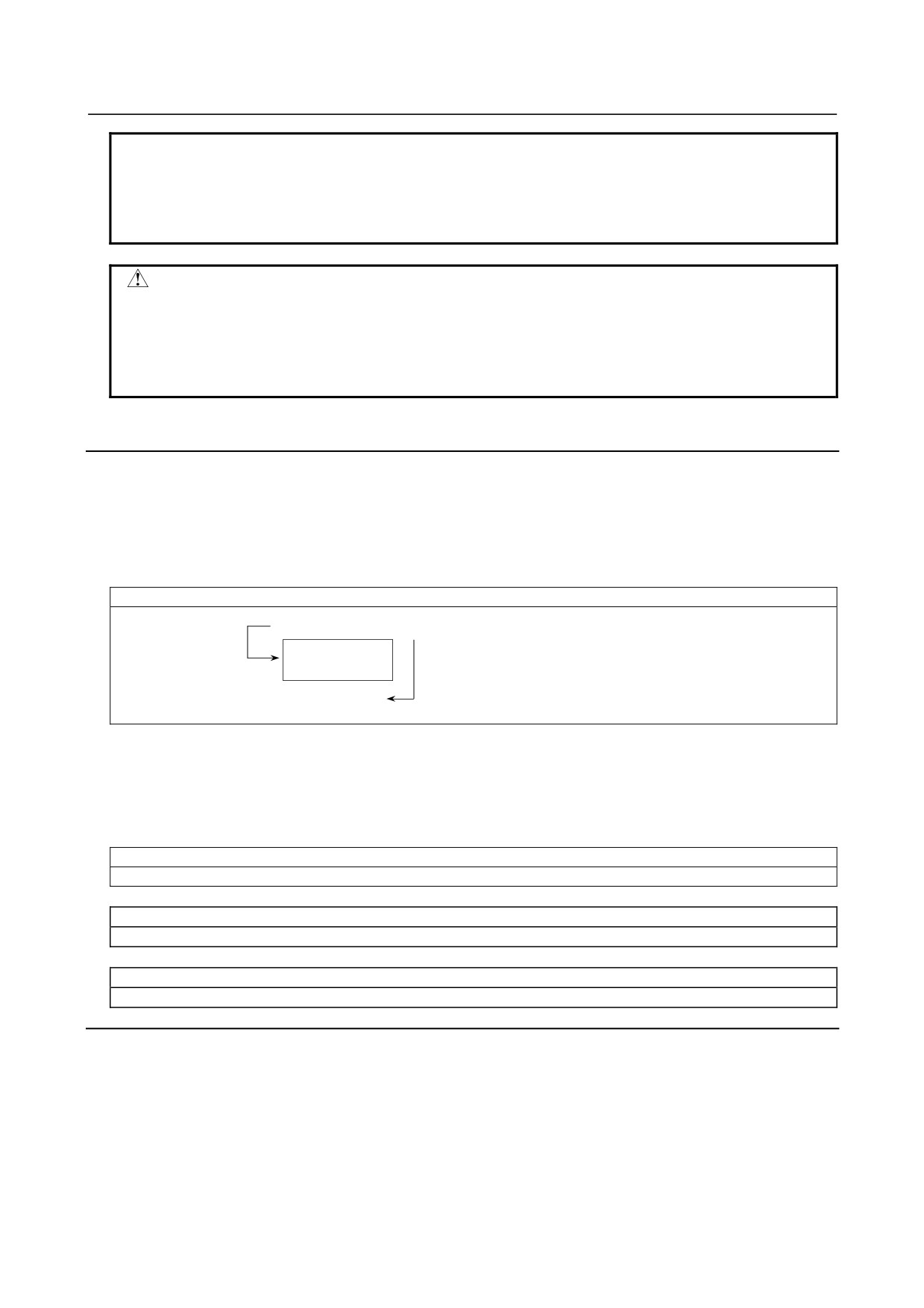
IF[<conditional expression>]GOTOn
If the specified <conditional expression> is satisfied (true), a branch to sequence number n occurs. If the
specified condition is not satisfied, the next block is executed.
If the value of variable #1 is greater than 10, a branch to sequence number N2 occurs.
IF [#1 GT 10] GOTO 2 ;
If the condition
is not satisfied
Processing
If the condition is satisfied
N2 G00 G91 X10.0
;
:
IF[<conditional expression>]THEN
If the specified <conditional expression> is satisfied (true), a macro statement specified after THEN is
executed.
Only a single macro statement is executed.
If the values of #1 and #2 are the same, 0 is assigned to #3.
IF[#1 EQ #2] THEN #3=0 ;
If the values of #1 and #2 are the same and those of #3 and #4 are also the same, 0 is assigned to #5.
IF[[#1 EQ #2] AND [#3 EQ #4]] THEN #5 = 0 ;
If the values of #1 and #2 are the same or those of #3 and #4 are the same, 0 is assigned to #5.
IF[[#1 EQ #2] OR [#3 EQ #4]] THEN #5 = 0 ;
Explanation
-
<Conditional expression>
<Conditional expressions> are divided into <simple conditional expressions> and <complex conditional
expressions>. In a <simple conditional expression>, a relational operator described in Table 14.5 (a) is
specified between two variables or between a variable and constant to be compared. An <expression>
can be used instead of a variable. With a <complex conditional expression>, an AND (logical AND),
OR (logical OR), or XOR (exclusive OR) operation is performed for the results (true or false) of multiple
<simple conditional expressions>.
- 203 -
14.CUSTOM MACRO
PROGRAMMING
B-64304EN/02
-
Relational operators
Relational operators each consist of two letters and are used to compare two values to determine whether
they are equal or one value is smaller or greater than the other value. Note that the equal sign (=) and
inequality sign (>, <) cannot be used as a relational operator.
Table 14.6 (a) Relational operators
Operator
Meaning
EQ
Equal to(=)
NE
Not equal to(≠)
GT
Greater than(>)
GE
Greater than or equal to(≥)
LT
Less than(<)
LE
Less than or equal to(≤)
Sample program
The sample program below finds the total of numbers 1 to 10.
O9500 ;
#1=0 ;
Initial value of the variable to hold the sum
#2=1 ;
Initial value of the variable as an addend
N1 IF[#2 GT 10] GOTO 2 ; Branch to N2 when the addend is greater than 10
#1=#1+#2 ;
Calculation to find the sum
#2=#2+1 ;
Next addend
GOTO 1 ;
Branch to N1
N2 M30 ;
End of program
14.6.4 Repetition (WHILE Statement)
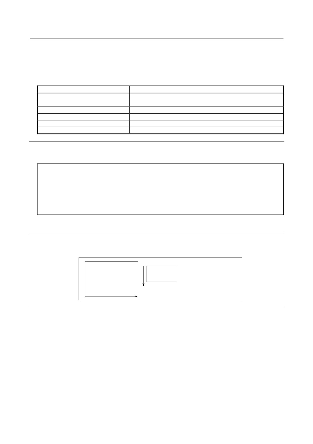
Specify a conditional expression after WHILE. While the specified condition is satisfied, the program
from DO to END is executed. If the specified condition is not satisfied, program execution proceeds to
the block after END.
WHILE [conditional expression] DO m ; (m=1,2,3)
If the
If the
Processing
condition
condition
is not
is satisfied
satisfied
END m
;
:
Explanation
While the specified condition is satisfied, the program from DO to END after WHILE is executed. If the
specified condition is not satisfied, program execution proceeds to the block after END. The same
format as for the IF statement applies. A number after DO and a number after END are identification
numbers for specifying the range of execution. The numbers 1, 2, and 3 can be used. When a number
other than 1, 2, and 3 is used, an alarm PS0126 occurs.
-
Nesting
The identification numbers (1 to 3) in a DO-END loop can be used as many times as desired. Note,
however, when a program includes crossing repetition loops (overlapped DO ranges), an alarm PS0124
occurs.
- 204 -
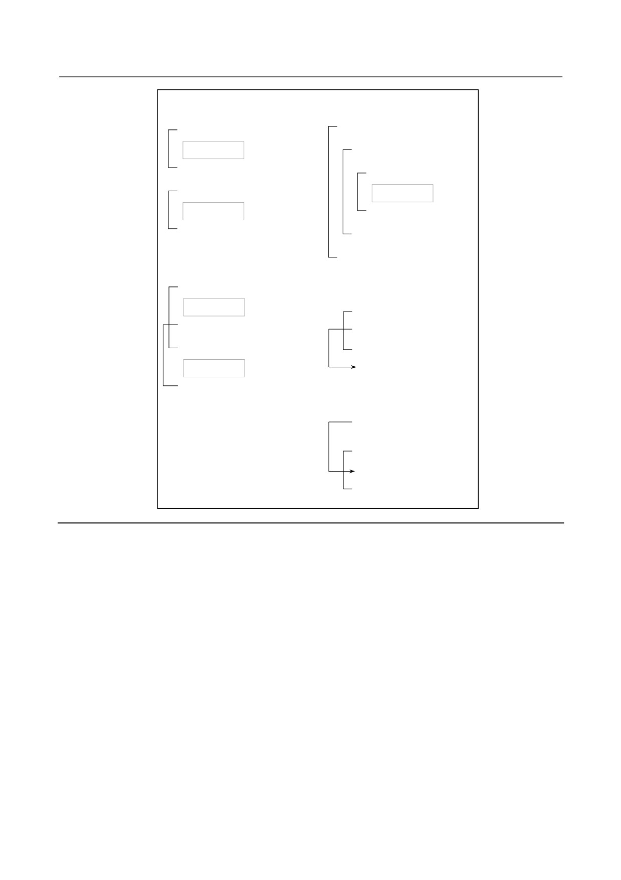
B-64304EN/02
PROGRAMMING
14.CUSTOM MACRO
1. The identification numbers (1 to
3. DO loops can be nested to a
3) can be used as many times
maximum depth of three levels.
as required.
WHILE [ … ] DO 1 ;
WHILE [ … ] DO 1 ;
:
Processing
WHILE [ … ] DO 2 ;
:
END 1 ;
WHILE [ … ] DO 3 ;
:
WHILE [ … ] DO 1 ;
Processing
Processing
END 3 ;
:
END 1 ;
END 2 ;
:
:
2. DO ranges cannot
END 1 ;
overlap.
4. Control can be transferred
WHILE [ … ] DO 1 ;
to the outside of a loop.
Processing
WHILE [ … ] DO 1 ;
WHILE [ … ] DO 2 ;
IF [ … ] GOTO n ;
:
END 1 ;
END 1 ;
Processing
Nn
END 2 ;
5. Branches cannot be made to a
location within a loop.
IF [ … ] GOTO n ;
:
WHILE [ … ] DO 1 ;
:
Nn … ;
END 1 ;
Limitation
-
Infinite loops
When DO m is specified without specifying the WHILE statement, an infinite loop ranging from DO to
END is produced.
-
Processing time
When a branch to the sequence number specified in a GOTO statement occurs, the sequence number is
searched for. For this reason, processing in the reverse direction takes a longer time than processing in
the forward direction. Therefore, in the case of processing in the reverse direction, use the WHILE
statement for repetition to reduce processing time.
-
Undefined variable
In a conditional expression that uses EQ or NE, a <null> and zero have different effects. In other types
of conditional expressions, a <null> is regarded as zero.
- 205 -
14.CUSTOM MACRO
PROGRAMMING
B-64304EN/02
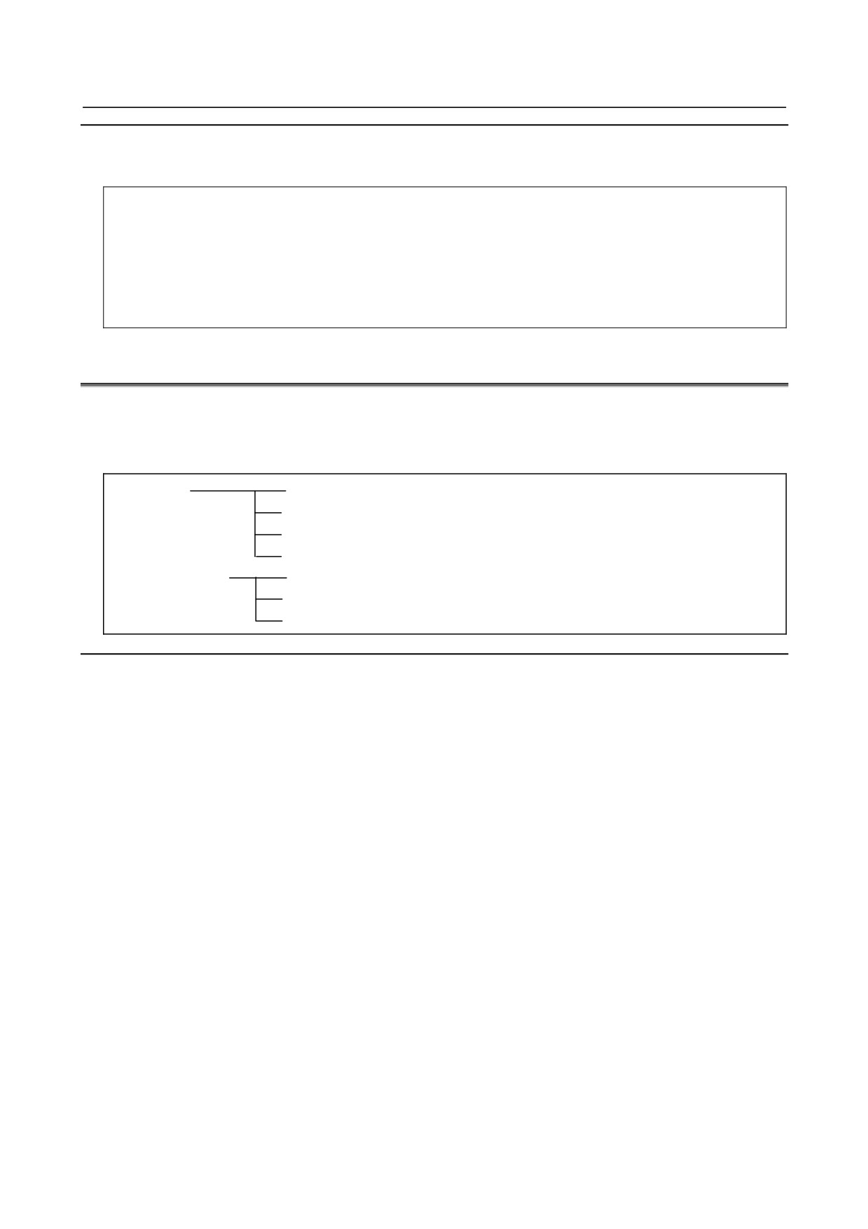
Sample program
The sample program below finds the total of numbers 1 to 10.
O0001;
#1=0;
#2=1;
WHILE[#2 LE 10] DO 1;
#1=#1+#2;
#2=#2+1;
END 1;
M30;
14.7 MACRO CALL
A macro program can be called using the following methods. The calling methods can roughly be divided
into two types: macro calls and subprogram calls.
A macro program can also be called during MDI operation in the same way.
Macro call
Simple call (G65)
Modal call (G66, G67)
Macro call using a G code
Macro call using an M code
Subprogram call
Subprogram call using an M code
Subprogram call using a T code
Subprogram call using a specific code
Limitation
-
Call nesting
Macro calls can be nested to a depth of up to five levels and subprogram calls can be nested to a depth of
up to ten levels; calls can be nested to a depth of up to 15 levels in total.
-
Differences between macro calls and subprogram calls
Macro call (G65, G66, Ggg, or Mmm) differs from subprogram call (M98, Mmm, or Ttt) as described
below.
• With a macro call, an argument (data passed to a macro) can be specified. A subprogram call does
not have this capability.
• If a macro call block contains another NC command (such as G01 X100.0 G65 Pp), an alarm
PS0127 occurs.
• If a subprogram call block contains another NC command (such as G01 X100.0 M98 Pp), the
subprogram is called after the command is executed.
• In any macro call block, the machine does not stop in the single block mode.
If a subprogram call block contains another NC command (such as G01 X100.0 M98 Pp), the
machine stops in the single block mode.
• With a macro call, the level of local variables changes. With a subprogram call, the level of local
variables does not change.
(See "Local variable levels" in Limitation of Subsection 14.6.1.)
- 206 -
B-64304EN/02
PROGRAMMING
14.CUSTOM MACRO
14.7.1 Simple Call (G65)
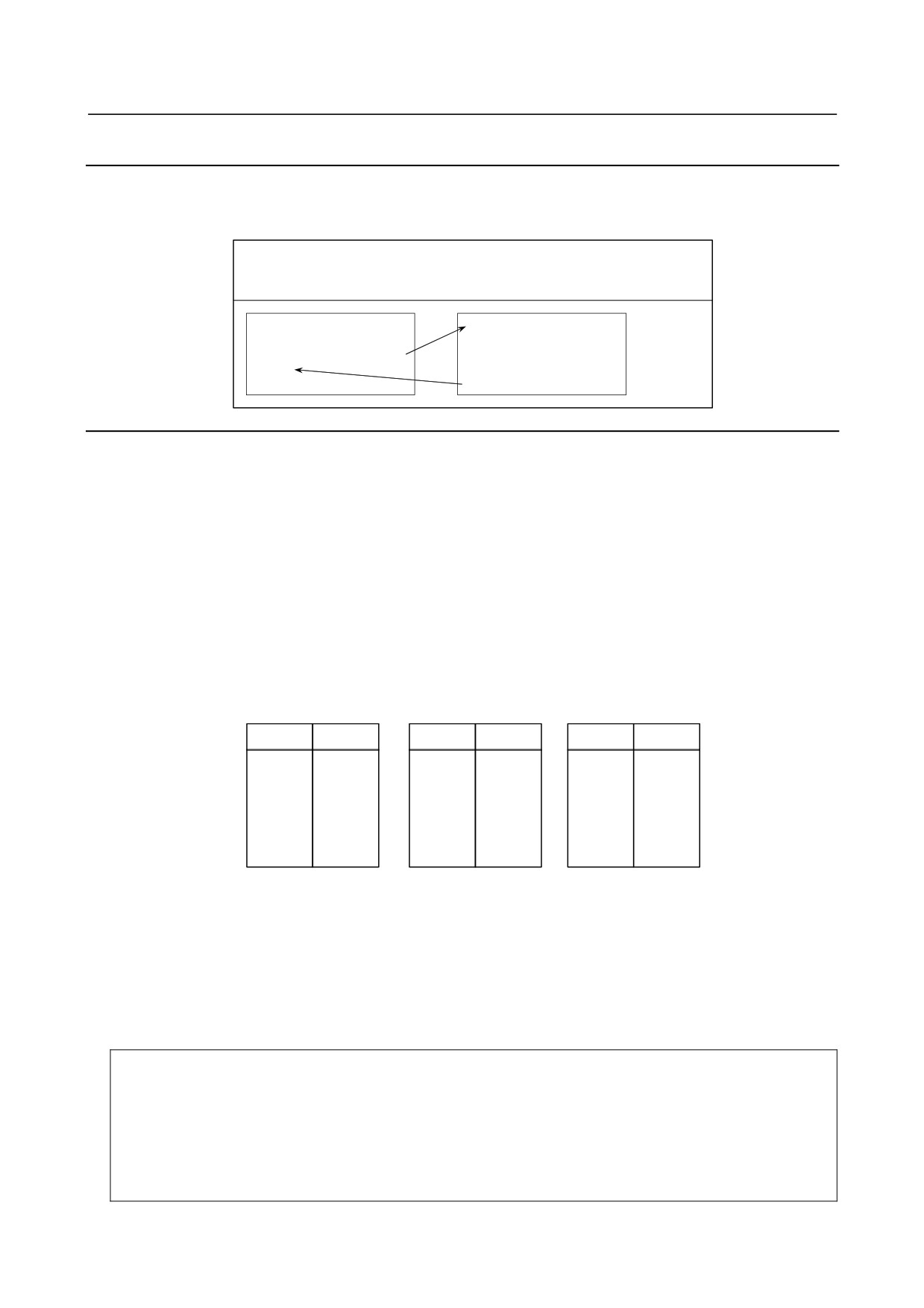
When G65 is specified, the custom macro specified at address P is called. Data (argument) can be
passed to the custom macro program.
G65 P p L l
<argument-
P : Number of the program to call
specification> ;
l
: Repetition count (1 by default)
Argument
:
Data passed to the macro
O0001 ;
O9010 ;
:
#3=#1+#2 ;
G65 P9010 L2 A1.0 B2.0 ;
IF [#3 GT 360] GOTO 9 ;
:
G00 G91 X#3 ;
M30 ;
N9 M99 ;
Explanation
-
Call
• After G65, specify at address P the program number of the custom macro to call.
• When a number of repetitions is required, specify a number from 1 to 999999999 after address L.
When L is omitted, 1 is assumed.
• By using argument specification, values are assigned to corresponding local variables.
-
Argument specification
Two types of argument specification are available. Argument specification I uses letters other than G, L,
O, N, and P once each. Argument specification II uses A, B, and C once each and also uses I, J, and K
up to ten times. The type of argument specification is determined automatically according to the letters
used.
•
Argument specification I
Address
Variable
Address
Variable
Address
Variable
number
number
number
A
#1
I
#4
T
#20
B
#2
J
#5
U
#21
C
#3
K
#6
V
#22
D
#7
M
#13
W
#23
E
#8
Q
#17
X
#24
F
#9
R
#18
Y
#25
H
#11
S
#19
Z
#26
• Addresses G, L, N, O, and P cannot be used in arguments.
• Addresses that need not be specified can be omitted. Local variables corresponding to an omitted
address are set to null.
• Addresses do not need to be specified alphabetically. They conform to word address format.
I, J, and K need to be specified alphabetically, however.
Argument specification I is always used for I, J, and K by setting bit 7 (IJK) of parameter No. 6008
to 1
Example
- When bit 7 (IJK) of parameter No. 6008 is 0, I_ J_ K_ means that I = #4, J = #5,
and K = #6 while K_ J_ I_ means K = #6, J = #8, and I= #10 because argument
specification II is used.
- When bit 7 (IJK) of parameter No. 6008 is 1, K_ J_ I_ means that I = #4, J = #5,
and K = #6, which is the same as with I_ J_ K_, because argument specification
I is used.
- 207 -
14.CUSTOM MACRO
PROGRAMMING
B-64304EN/02
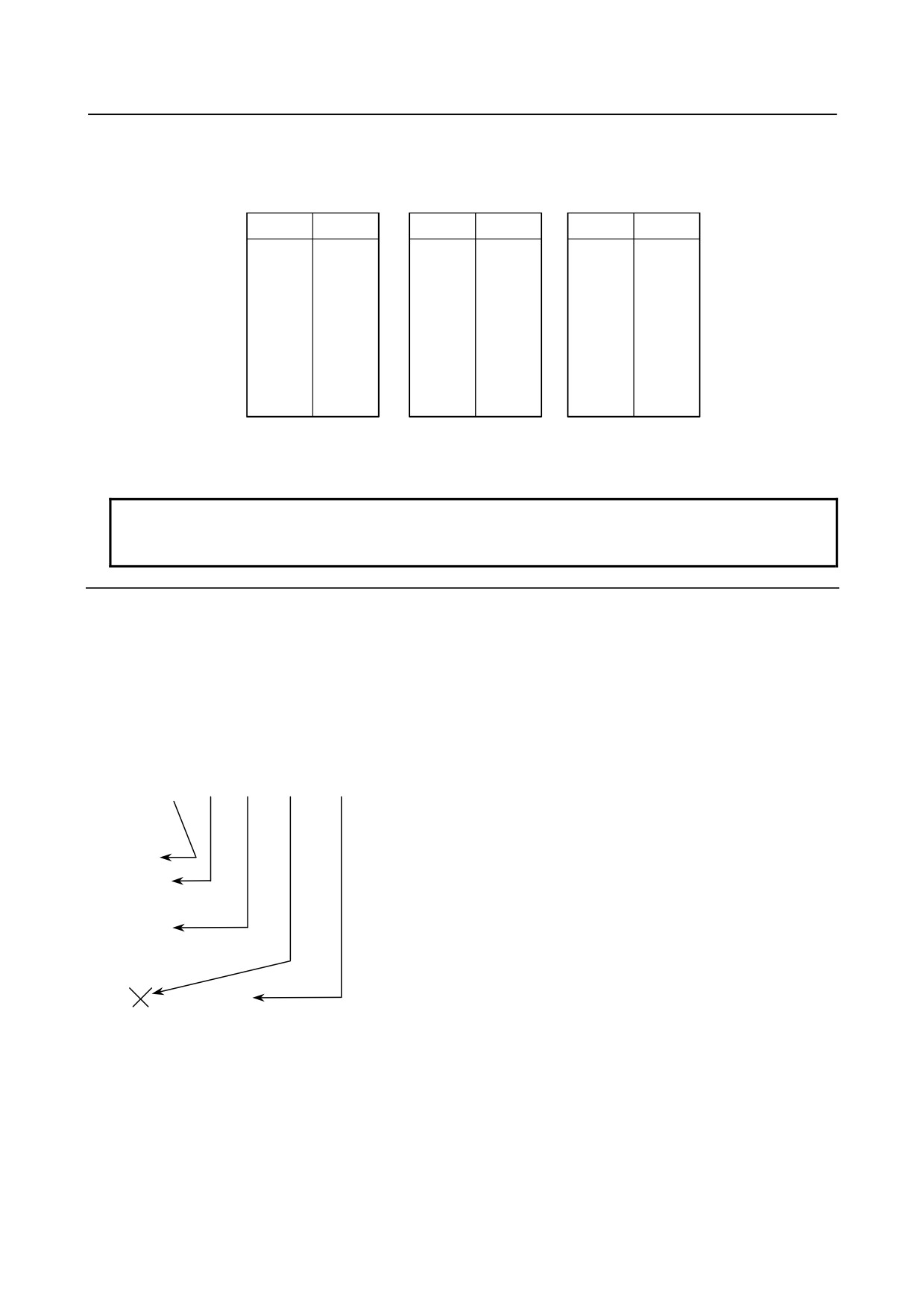
• Argument specification II
Argument specification II uses A, B, and C once each and uses I, J, and K up to ten times.
Argument specification II is used to pass values such as three-dimensional coordinates as arguments.
Address
Variable
Address
Variable
Address
Variable
number
number
number
A
#1
IK3
#12
J7
#23
B
#2
I4
#13
K7
#24
C
#3
J4
#14
I8
#25
I1
#4
K4
#15
J8
#26
J1
#5
I5
#16
K8
#27
K1
#6
J5
#17
I9
#28
I2
#7
K5
#18
J9
#29
J2
#8
I6
#19
K9
#30
K2
#9
J6
#20
I10
#31
I3
#10
K6
#21
J10
#32
J3
#11
I7
#22
K10
#33
• Subscripts of I, J, and K for indicating the order of argument specification are not written in the
actual program.
NOTE
When bit 7 (IJK) of parameter No. 6008 is 1, argument specification II cannot be
used.
Limitation
-
Format
G65 must be specified before any argument.
-
Mixture of argument specifications I and II
The CNC internally identifies argument specification I and argument specification II. If a mixture of
argument specification I and argument specification II is specified, the type of argument specification
specified later takes precedence.
[Example]
G65 A1.0 B2.0 I-3.0 I4.0 D5.0 P1000 ;
(Variables)
#1:1.0
#2:2.0
#3:
#4:-3.0
#5:
#6:
#7:4.0
5.0
When both the I4.0 and D5.0 arguments are commanded for variable #7 in this example, the latter, D5.0,
is valid.
-
Position of the decimal point
The units used for argument data passed without a decimal point correspond to the least input increment
of each address.
- 208 -
B-64304EN/02
PROGRAMMING
14.CUSTOM MACRO
CAUTION
The value of an argument passed without a decimal point may vary according to
the system configuration of the machine. It is good practice to use decimal
points in macro call arguments to maintain program compatibility.
M
When a value is specified with no decimal point, the number of decimal places is determined as follows.
Address
For a non-axis address
For an axis address
D, E, H, M, S, or T
0
Q or R
α (NOTE 2)
A, C, I, J, K, X, Y, or Z
α (NOTE 2)
β (NOTE 3)
B, U, V(NOTE 1), or W
0
β (NOTE 3)
Second auxiliary function
γ (NOTE 4)
Address
Metric input
Inch input
F (G93 mode)
3
F (G94 mode)
0
2
F (G95 mode)
2 (NOTE 5)
4 (NOTE 5)
NOTE
1 When V is used in a call using a specific address, the number of decimal places
is determined according to the setting for the reference axis.
2 α is determined according to the increment system for the reference axis (axis
specified with parameter No. 1031) as listed in the table in NOTE 4.
3 β is determined according to the increment system for the corresponding axis
address as listed in the following table.
Increment system
Linear axis (metric input)
Linear axis (inch input)
Rotation axis
IS-A
2
3
2
IS-B
3
4
3
IS-C
4
5
4
When bit 7 (IPR) of parameter No. 1004 is set to 1, the above values from which
1 is subtracted are used. When the increment system for an axis is IS-A,
however, the setting of bit 7 (IPR) of parameter No. 1004 is not effective.
When calculator-type decimal notation for each axis is used (bit 0 (ADX) of
parameter No. 3455 is set to 1), the number of decimal places is 0. When bit 7
(EAP) of parameter No. 3452 is set to 1, however, calculator-type decimal
notation is not effective and the number of decimal places is determined as listed
in the above table.
4
γ is determined according to the increment system for the reference axis (axis
specified with parameter No. 1031) as listed in the following table.
(When bit 7
(BDX) of parameter No. 3450 is set to 1, γ is also determined in the same way.)
AUP
AUP(3450#0) = 1
Increment system for
(No.3450#0)
AUX (No.3405#0) = 0
AUX (No.3405#0) = 1
the reference axis
= 0
Metric
Inch
Metric
Inch
IS-A
2
2
3
IS-B
0
3
3
4
IS-C
4
4
5
- 209 -
14.CUSTOM MACRO
PROGRAMMING
B-64304EN/02
NOTE
5 When bit 1 (FR3) of parameter No. 1405 is 1, the values in the table need to be
incremented by 1.
6 When calculator-type decimal notation is used (bit 0 (DPI) of parameter No. 3401
is set to 1), the number of decimal places is 0.
T
When a value is specified with no decimal point, the number of decimal places is determined as follows.
Address
For a non-axis address
For an axis address
H, M, Q, S, or T
0
R
α (NOTE 1)
D
0/α (NOTE 6)
A, B, C, I, J, K, U, V, W, X, Y, or Z
α (NOTE 1)
β (NOTE 2)
Second auxiliary function
γ (NOTE 3)
Address
Metric input
Inch input
E, F (G98 mode)
0 (NOTE 4)
2 (NOTE 4)
E, F (G99 mode)
4
6
NOTE
1 α is determined according to the increment system for the reference axis (axis
specified with parameter No. 1031) as listed in the table in NOTE 2.
2 β is determined according to the increment system for the corresponding axis
address as listed in the following table.
Increment system
Linear axis (metric input)
Linear axis (inch input)
Rotation axis
IS-A
2
3
2
IS-B
3
4
3
IS-C
4
5
4
When bit 7 (IPR) of parameter No. 1004 is set to 1, the above values from which
1 is subtracted are used. When the increment system for an axis is IS-A,
however, the setting of bit 7 (IPR) of parameter No. 1004 is not effective.
When calculator-type decimal notation for each axis is used (bit 0 (ADX) of
parameter No. 3455 is set to 1), the number of decimal places is 0. When bit 7
(EAP) of parameter No. 3452 is set to 1, however, calculator-type decimal
notation is not effective and the number of decimal places is determined as listed
in the above table.
3 γ is determined according to the increment system for the reference axis (axis
specified with parameter No. 1031) as listed in the following table.
(When bit 7
(BDX) of parameter No. 3450 is set to 1, γ is also determined in the same way.)
AUP(3450#0) = 1
Increment system for
AUP (No.3450#0)
AUX (No.3405#0) = 0
AUX (No.3405#0) = 1
the reference axis
= 0
Metric
Inch
Metric
Inch
IS-A
2
2
3
IS-B
0
3
3
4
IS-C
4
4
5
- 210 -
B-64304EN/02
PROGRAMMING
14.CUSTOM MACRO
NOTE
4 When bit 2 (FM3) of parameter No. 1404 is 1, the values in the table need to be
incremented by 3.
5 When calculator-type decimal notation is used (bit 0 (DPI) of parameter No. 3401
is set to 1), the number of decimal places is 0.
6 When bit 2 (DPD) of parameter No. 6019 is set to 0, the number of decimal places
is 0.
When bit 2 (DPD) of parameter No. 6019 is set to 1, the number of decimal places
is α.
-
Call nesting
Macro calls can be nested to a depth of up to five levels including simple calls (G65) and modal calls
(G66). Subprogram calls can be nested to a depth of up to 15 levels including macro calls.
A macro program can also be called during MDI operation in the same way.
-
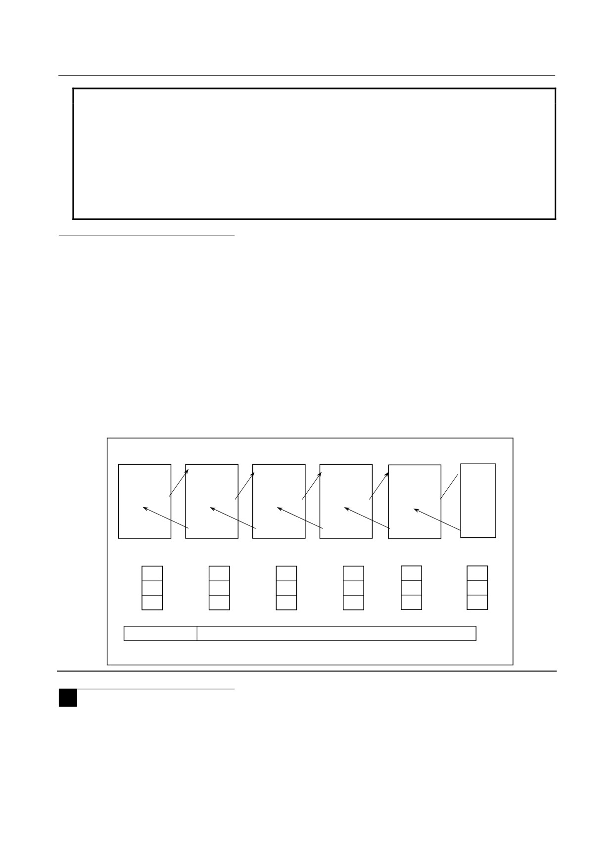
Local variable levels
• Local variables from level 0 to 5 are provided for nesting.
• The level of the main program is 0.
• Each time a macro is called (with G65, G66, Ggg, or Mmm), the local variable level is incremented
by one. The values of the local variables at the previous level are saved in the CNC.
• When M99 is executed in a macro program, control returns to the calling program. At that time,
the local variable level is decremented by one; the values of the local variables saved when the
macro was called are restored.
Main program
Macro
Macro
Macro
Macro
Macro
(level 0)
(level 1)
(level 2)
(level 3)
(level 4)
(level 5)
O0001 ;
O0002 ;
O0003 ;
O0004 ;
O0005 ;
O0006
:
:
:
:
:
:
#1=1 ;
:
:
:
:
:
G65 P2 A2 ;
G65 P3 A 3;
G65 P4 A4 ;
G65 P5 A5 ;
G65 P6 A6 ;
:
:
:
:
:
:
:
:
:
:
:
:
:
M30 ;
M99 ;
M99 ;
M99 ;
M99 ;
M99 ;
Local variables
(Level 1)
(Level 2)
(Level 3)
(Level 4)
(Level 5)
(level 0)
1
2
3
4
5
6
#1
#1
#1
#1
#1
#1
:
:
:
:
:
:
:
:
:
:
:
:
:
:
:
:
:
:
#33
#33
#33
#33
#33
#33
Common variables
and written to by macros at different levels
#100-, #500-
Variables that can be read from
Sample program (bolt hole circle)
M
A macro is created which drills H holes at intervals of B degrees after a start angle of A degrees along the
periphery of a circle with radius I.
The center of the circle is (X,Y). Commands can be specified in either the absolute or incremental
programming.
To drill in the clockwise direction, specify a negative value for B.
- 211 -

14.CUSTOM MACRO
PROGRAMMING
B-64304EN/02
H=2
H=3
H=1
H=4
B
B
A
Center (X,Y)
Radius I
-
Calling format
G65 P9100 Xx Yy Zz Rr Ff Ii Aa Bb Hh ;
X
:
X coordinate of the center of the circle
(absolute or incremental programming)
(#24)
Y
:
Y coordinate of the center of the circle
(absolute or incremental programming)
(#25)
Z
:
Hole depth
(#26)
R
:
Coordinates of an approach point
(#18)
F
:
Cutting feedrate
(#9)
I
:
Radius of the circle
(#4)
A
:
Drilling start angle
(#1)
B
:
Incremental angle
(clockwise when a negative value is specified)
(#2)
H
:
Number of holes
(#11)
-
Program calling a macro program
O0002 ;
G90 G92 X0 Y0 Z100.0 ;
G65 P9100 X100.0 Y50.0 R30.0 Z-50.0 F500 I100.0 A0 B45.0 H5 ;
M30 ;
-
Macro program (called program)
O9100 ;
#3=#4003 ;
Stores G code of group 3.
G81 Z#26 R#18 F#9 K0 ; (Note).. Drilling cycle.
Note: L0 can also be used.
IF[#3 EQ 90]GOTO 1 ;
Branches to N1 in the G90 mode.
#24=#5001+#24 ;
Calculates the X coordinate of the center.
#25=#5002+#25 ;
Calculates the Y coordinate of the center.
N1 WHILE[#11 GT 0]DO 1 ;
Until the number of remaining holes reaches 0
#5=#24+#4*COS[#1] ;
Calculates a drilling position on the X-axis.
#6=#25+#4*SIN[#1] ;
Calculates a drilling position on the Y-axis.
G90 X#5 Y#6;
Performs drilling after moving to the target position.
#1=#1+#2 ;
Updates the angle.
#11=#11-1 ;
Decrements the number of holes.
END 1 ;
G#3 G80 ;
Returns the G code to the original state.
M99 ;
- 212 -
B-64304EN/02
PROGRAMMING
14.CUSTOM MACRO
Meaning of variables:
Stores the G code of group 3.
#5: X coordinate of the next hole to drill
#6: Y coordinate of the next hole to drill
Sample program (Drill cycle)
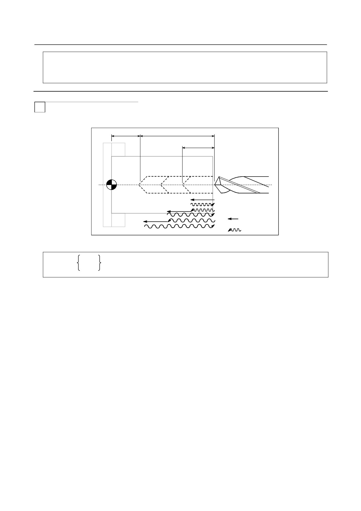
T
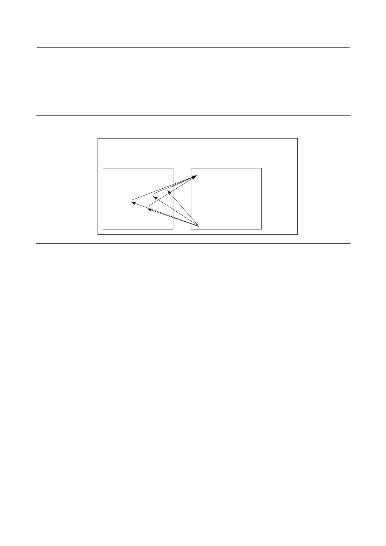
Move the tool beforehand along the X- and Z-axes to the position where a drilling cycle starts. Specify
Z or W for the depth of a hole, K for the depth of a cut, and F for the cutting feedrate to drill the hole.
Z
W
K
Cutting
Rapid traverse
-
Calling format
Zz
G65 P9100
Kk Ff ;
Ww
Z
:
Hole depth (absolute programming)
W
:
Hole depth (incremental programming)
K
:
Cutting amount per cycle
F
:
Cutting feedrate
-
Program calling a macro program
O0002 ;
G50 X100.0 Z200.0 ;
G00 X0 Z102.0 S1000 M03 ;
G65 P9100 Z50.0 K20.0 F0.3 ;
G00 X100.0 Z200.0 M05 ;
M30 ;
-
Macro program (called program)
O9100;
#1=0 ;
Clear the data for the depth of the current hole.
#2=0 ;
Clear the data for the depth of the preceding hole.
IF [#23 NE #0] GOTO 1 ;
If incremental programming, specifies the jump to N1.
IF [#26 EQ #0] GOTO 8 ;
If neither Z nor W is specified, an error occurs.
#23=#5002-#26 ;
Calculates the depth of a hole.
N1
#1=#1+#6 ;
Calculates the depth of the current hole.
IF [#1 LE #23] GOTO 2 ;
Determines whether the hole to be cut is too deep?
#1=#23 ;
Clamps at the depth of the current hole.
N2 G00 W-#2 ;
Moves the tool to the depth of the preceding hole at the cutting feedrate.
G01 W- [#1-#2] F#9 ;
Drills the hole.
G00 W#1 ;
Moves the tool to the drilling start point.
- 213 -
14.CUSTOM MACRO
PROGRAMMING
B-64304EN/02
IF [#1 GE #23] GOTO 9 ;
Checks whether drilling is completed.
#2=#1 ;
Stores the depth of the current hole.
GOTO 1 ;
N9 M99 ;
N8
#3000=1 (NOT Z OR W COMMAND) ;
Issues an alarm.
14.7.2 Modal Call: Call After the Move Command (G66)
Once G66 is issued to specify a modal call a macro is called after a block specifying movement along
axes is executed. This continues until G67 is issued to cancel a modal call.
G66 P p L l <argument-specification> ; P : Number of the program to call
l
: Repetition count (1 by default)
Argument : Data passed to the macro
O0001 ;
O9100 ;
:
:
G66 P9100 L2 A1.0 B2.0 ;
G00 Z-#1 ;
G00 G90 X100.0 ;
G01 Z-#2 F300 ;
Y200.0 ;
:
X150.0 Y300.0 ;
:
G67 ;
:
:
:
M30 ;
M99 ;
Explanation
-
Call
• After G66, specify at address P a program number subject to a modal call.
• When a number of repetitions is required, a number from 1 to 999999999 can be specified at address
L.
• As with a simple call (G65), data passed to a macro program is specified in arguments.
• In the G66 mode, a macro can be called.
-
Cancellation
When a G67 code is specified, modal macro calls are no longer performed in subsequent blocks.
-
Call nesting
Macro calls can be nested to a depth of up to five levels including simple calls (G65) and modal calls
(G66). Subprogram calls can be nested to a depth of up to 15 levels including macro calls.
-
Modal call nesting
For a single modal call (when G66 is specified only once), each time the move command is executed, the
specified macro is called. When nested modal macro calls are specified, the macro at the next higher
level is called each time the move command for a macro call is executed.
Macros are called in reverse order in which they are specified. Each time G67 is issued, the macros are
canceled one by one in reverse order in which they are specified.
[Example]
G66 P9100 ;
O9100 ;
O9200 ;
X10.0 ;
(1-1)
Z50.0 ;
(2-1)
X60.0 ;
(3-1)
G66 P9200 ;
M99 ;
Y70.0 ;
(3-2)
X15.0 ;
(1-2)
M99;
G67 ;
Cancels P9200.
G67 ;
Cancels P9100.
X-25.0 ;
(1-3)
- 214 -
B-64304EN/02
PROGRAMMING
14.CUSTOM MACRO
Execution order of the above program (blocks not containing the move command omitted)
(1-1)
(1-2)
(1-3)
(2-1)
(3-1)
(3-2)
(2-1)
(2-1)
* No modal call is performed after (1-3) because the mode is not the macro call mode.
Limitation
• G66 and G67 blocks are specified in pairs in the same program. If a G67 code is specified not in
the G66 mode, an alarm PS1100 occurs. Bit 0 (G67) of parameter No. 6000 can be set to 1 to
specify that the alarm does not occur in this case.
• In a G66 block, no macros can be called. Local variables (arguments) are set, however.
• G66 needs to be specified before any arguments.
• No macros can be called in a block which contains a code such as a auxiliary function that does not
involve movement along an axis.
• Local variables (arguments) can only be set in G66 blocks. Note that local variables are not set
each time a modal call is performed.
NOTE
If M99 is specified in a block in which a call is performed, it is executed after the
call is performed.
Sample program
M
The same operation as the drilling canned cycle G81 is created using a custom macro and the machining
program makes a modal macro call. For program simplicity, all drilling data is specified using absolute
values.
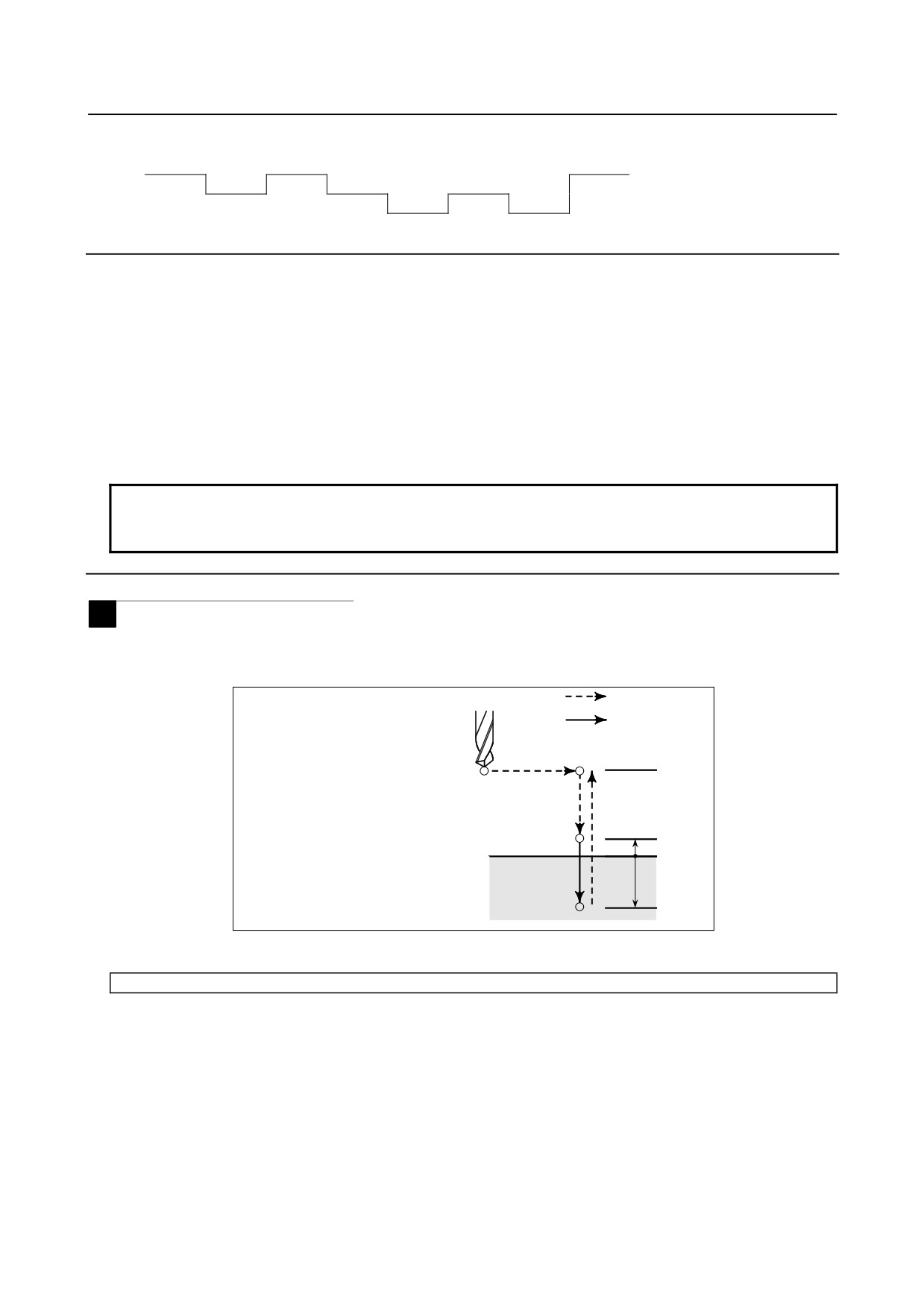
Rapid traverse
The canned cycle consists of the following
basic operations:
Cutting feed
Operation 1: Positioning along the X-axis
Operation 1
Point I
and Y-axis
Operation 2: Rapid traverse to point R
Operation 2
Operation 4
Operation 3: Cutting feed to point Z
R
Point R
Operation 4: Rapid traverse to point R or I
Z=0
Operation 3
Point Z
Z
-
Calling format
G66 P9110 Zz Rr Ff Ll
;
Z
: Coordinates of position Z (absolute programming only)
(#26)
R
: Coordinates of position R (absolute programming only)
(#18)
F
: Cutting feedrate
(#9)
L
: Repetition count
-
Program that calls a macro program
O0001 ;
G28 G91 X0 Y0 Z0 ;
G92 X0 Y0 Z50.0 ;
G00 G90 X100.0 Y50.0 ;
- 215 -