FANUC Series 0i-MODEL D, Series 0i Mate-MODEL D. OPERATOR'S MANUAL - page 6
10.TOOL FUNCTION (T FUNCTION) PROGRAMMING
B-64304EN/02
- Codes for specifying a tool offset value
M
Codes for specifying a tool offset value include an H code (for tool length offset) and a D code (for cutter
compensation). Numbers up to 400 (up to three digits long) can be registered as codes for specifying
tool offset values.
NOTE
If codes for specifying tool offset values are not used, the registration of these
codes can be omitted.
T
Neither H code nor D code is used as a code for specifying tool offset values. The T code includes a
compensation code.
- Tool life value
A tool life value can be registered in terms of use duration or use count. The maximum value is as
follows:
Up to 4300 minutes can be registered if duration specification is selected, or up to 65535 times can be
registered if use count specification is selected.
- Remaining life setting
Parameters Nos. 6844 and 6845 are used to set the life remaining until a new tool is selected.
10.2.2 Registering, Changing, and Deleting Tool Life Management
Data
By programming, tool life management data can be registered in the CNC, and registered tool life
management data can be changed or deleted.
Explanation
The program format varies depending on the following four types of operation:
- Registration after deletion of all groups
After all registered tool life management data is deleted, programmed tool life management data is
registered.
- Change of tool life management data
Tool life management data can be set for a group for which no tool life management data is registered,
and already registered tool life management data can be changed.
- Deletion of tool life management data
Tool life management data can be deleted.
- Setting of tool life count type
A count type (use duration or use count) can be set for each group separately.
Format
- Registration after deletion of all groups
- 126 -
B-64304EN/02
PROGRAMMING 10.TOOL FUNCTION (T FUNCTION)
M
Format
Meaning
G10 L3 ;
G10L3: Register data after deleting data of all groups.
P- L- ;
P-: Group number
T- H- D- ;
L-: Tool life value
T- H- D- ;
T-: Tool number
:
H-: Code for specifying tool offset value (H code)
P- L- ;
D-: Code for specifying tool offset value (D code)
T- H- D- ;
G11: End of registration
T- H- D- ;
:
G11 ;
M02(M30) ;
T
Format
Meaning
G10 L3 ;
G10L3: Register data after deleting data of all groups.
P- L- ;
P-: Group number
T- ;
L-: Tool life value
T- ;
T-: Tool number and tool offset number
:
G11: End of registration
P- L- ;
T- ;
T- ;
:
G11 ;
M02(M30) ;
If more than one offset value is to be used for the same tool within one process, specify the command as
shown below (on the assumption that tool offset numbers are two digits long).
Format
Meaning
G10 L3 ;
P- L- ;
T0101 ;
Tool number 01, tool offset number 01
T0102 ;
Tool number 01, tool offset number 02
T0103 ;
Tool number 01, tool offset number 03
:
G11 ;
M02(M30) ;
- Change of tool life management data
M
Format
Meaning
G10 L3 P1 ;
G10L3P1: Start changing group data.
P- L- ;
P-: Group number
T- H- D- ;
L-: Tool life value
T- H- D- ;
T-: Tool number
:
H-: Code for specifying tool offset value (H code)
P- L- ;
D-: Code for specifying tool offset value (D code)
T- H- D- ;
G11: End of change of group
T- H- D- ;
:
G11 ;
M02(M30) ;
- 127 -
10.TOOL FUNCTION (T FUNCTION) PROGRAMMING
B-64304EN/02
T
Format
Meaning
G10 L3 P1 ;
G10L3P1: Start changing group data.
P- L- ;
P-: Group number
T- ;
L-: Tool life value
T- ;
T-: Tool number and tool offset number
:
G11: End of registration
P- L- ;
T- ;
T- ;
:
G11 ;
M02(M30) ;
-
Deletion of tool life management data
Format
Meaning
G10 L3 P2 ;
G10L3P2: Start deleting group data.
P- ;
P-: Group number
P- ;
G11: End of deletion
P- ;
P- ;
:
G11 ;
M02(M30) ;
-
Setting of tool life count type
Format
Meaning
G10 L3 ;
(or G10 L3 P1) ;
P- L- Q- ;
T- H- D- ;
Q:
Life count type
T- H- D- ;
(1: Use count.
2: Duration.)
:
G11 ;
M02(M30) ;
CAUTION
If the Q command is omitted, the life count type is set according to the setting of
bit 2 (LTM) of parameter No. 6800.
Tool life value
A tool life value is registered as a duration or a use count according to the setting of bit 2 (LTM) of
parameter No. 6800 or the setting of a count type (Q command). The maximum values are listed below.
Table 10.2.2 (a) Life count types and maximum life values
LFB
LTM
Life count type
Maximum life value
(No.6805#4)
(No.6800#2)
0
Use count specification
65535 times
0
1
Duration specification
4300 minutes
If the count type is duration specification, the unit of a life value specified with address L in a program
may be one minute or 0.1 second, which is determined by the setting of bit 1 (FGL) of parameter No.
6805.
- 128 -
B-64304EN/02
PROGRAMMING 10.TOOL FUNCTION (T FUNCTION)
Table 10.2.2 (b) Life value unit and maximum value in L command
LFB
FGL
Maximum value in
Life value unit
Example
(No.6805#4)
(No.6805#1)
L command
L100:
0
1 minute
4300
Life value is 100 minutes.
0
L1000:
1
0.1 second
2580000
Life value is 100 seconds.
10.2.3 Tool Life Management Commands in Machining Program
Explanation
M
- Commands
The following commands are used for tool life management:
T○○○○○○○○ ;
Specifies a tool group number.
The tool life management function selects, from a specified group, a tool whose life has not expired, and
outputs its T code signal.
In {{{{{{{{
, specify the sum of the tool life management ignore number specified in parameter
No. 6810 and a desired group number.
Example:
To specify tool group number 1 when the tool life management ignore number is 100, specify
“T101;”.
NOTE
If {{{{{{{{
is not greater than a tool life management ignore number, the
T code is treated as an ordinary T code.
M06;
Terminates tool life management for the previously used tools, and begins counting the life of a new tool
selected with the T code.
NOTE
1 M06 is treated as an M code not involving buffering.
2 If more than one M code is to be specified within the same block, specify M06
first among these M codes.
H99;
Selects the H code registered in tool life management data for the currently used tool to enable tool length
offset. Parameter No. 13265 can be used to enable compensation according to an H code other than
H99.
H00;
Cancels tool length offset.
D99;
Selects the D code registered in tool life management data for the currently used tool to perform cutter
compensation.
Parameter No. 13266 can be used to enable compensation according to a D code other than D99.
- 129 -
10.TOOL FUNCTION (T FUNCTION) PROGRAMMING
B-64304EN/02
D00;
Cancels cutter compensation.
NOTE
H99 and D99 must be specified after the M06 command. If a code other than
the H/D code set in H99/D99 or parameters Nos. 13265 and 13266 is specified
after M06, the H code or D code of tool life management data is not selected.
-
Types
For tool life management, the four tool change types (types A to D) listed below are used. Which type
to use varies from one machine to another. For details, refer to the relevant manual of each machine tool
builder.
Table 10.2.3 Differences among tool change types
Tool change type
A
B
C
D
Parameters M6T and
M6T
M6E
M6T
M6E
M6T
M6E
M6T
M6E
M6E
M6T (No.6800#7)
0
0
1
0
1
0
1
M6E (No.6801#7)
Tool group number
specified in the same
Tool group already
Tool group to be used next
block as the tool change
used
command (M06)
Life counting is
performed if a tool
Time when tool life is
Life counting is performed for a tool in the specified tool group if M06
in the tool group
counted
is specified next.
specified in the
same block as M06
is specified.
If the T command (retract tool
Normally, if a tool group number
group) following the M06
command is specified alone, type B is
command is not the currently
used. However, even if a tool group
If M06 is specified
Remarks
used tool group, alarm
number command is specified alone
alone, alarm
PS0155 is issued (if bit 6
with type C, no alarm is issued.
(This
PS0153 is raised.
(IGI) of parameter No. 6800 =
means that there is no difference in
0).
operation between types B and C.)
NOTE
If a tool group number is specified and a new tool is selected, the new tool
selection signal is output.
T
- Commands
T{{{{{{
99;
The tool life management function ends counting the life of the tool used so far, selects, from the group
specified by {{{{{{
, a tool whose life has not expired, outputs the T code signal for the tool, and
starts counting the life of the tool.
Example:
Suppose that a T199 command (with a tool offset specified with the lower two digits) is issued to
cause the tool life management function to select T10001 of tool group 1. Then, T code 100 is
output, and the tool offset number 1 is selected.
- 130 -
B-64304EN/02
PROGRAMMING 10.TOOL FUNCTION (T FUNCTION)
If the condition that a new tool be selected is not met, and the second or subsequent selection of the same
group is made since the entry of the control unit into the automatic operation start state from the reset
state, the next to the currently selected T code is selected if more than one offset is registered.
If the third selection is made, for example, the third offset is selected from among multiple offsets
registered for the same tool.
Example:
As shown below, suppose that two T codes (with a tool offset specified in the lower two digits)
having the same tool number and multiple offset numbers are set in group 1.
T10001 T10002
The first T199 command issued since the entry of the control unit into the automatic operation start
state from the reset state selects the first T code, T10001. Then, if T199 is issued again before the
control unit is reset, the second T code, T10002, is selected. Furthermore, if T199 is issued again
before the control unit is reset, the second T code, T10002, is selected because no third offset is
present.
Setting bit 1 (TSM) of parameter No. 6801 set to 1 enables life counting to be performed for each T
code separately even if T codes specifying multiple offsets for the same number are registered.
T{{{{{{
88;
The offset of the tool whose life is currently counted by tool life management is canceled. The tool
offset code is set to 00, and the tool number is output as a T code signal.
Example:
Suppose that the tool number of the tool currently used by the tool life management function is 100.
Then, issuing a T188 command (with a tool offset specified with the lower two digits) outputs T
code 100 and selects offset number 0, canceling the offset.
NOTE
If life counting is not performed, or if the specified tool does not belong to the
group for which life counting is being performed, alarm PS0155 is issued.
The numbers of digits in {{{{{{
and 99/88 vary as follows:
No.5028
99
88
1
T{{{{{{{
9
T{{{{{{{
8
↑
↑
↑
↑
Select group Start life counting
Select group Cancel tool offset
2
T{{{{{{
99
T{{{{{{
88
↑
↑
↑
↑
Select group Start life counting
Select group Cancel tool offset
3
T{{{{{
999
T{{{{{
888
↑
↑
↑
↑
Select group Start life counting
Select group Cancel tool offset
The maximum number of digits in T codes is set in parameter No. 3032.
The number of digits used for specifying an offset number is selected by parameter No. 5028. If 0 is
selected, the number of digits depends on the number of tool offsets.
Example:
If there are one to nine tool offsets: Lowest digit
If there are 10 to 99 tool offsets:
Lower two digits
If there are 100 to 200 tool offsets:
Lower three digits
- 131 -

10.TOOL FUNCTION (T FUNCTION) PROGRAMMING
B-64304EN/02
NOTE
Offset start and cancel operations involve compensation by moving a tool or by
shifting the coordinate system. Using bit 6 (LWM) of parameter No. 5002 can
select whether to perform a compensation operation if a T code is specified or if
an axis move command is specified.
For details, refer to Subsection 5.1.5, “Offset Operation,” of the lathe system
OPERATOR’S MANUAL (B-63944EN-1).
T{{{{{{
ΔΔ;
If the tool offset number in ΔΔ is neither 99 nor 88, the T code is treated as an ordinary T code. If life
counting is being currently performed, it is ended.
Examples
M
- Tool change type A
If a block specifying a tool change command (M06) also contains a tool group command (T code), the T
code is used as a command for returning the tool to its cartridge. By specifying a tool group number
with a T code, the number of the tool used so far is output as a T code signal. If the specified tool
number is not a tool number of the tool group of the tool being used, alarm PS0155 is issued. The alarm,
however, can be suppressed by setting bit 6 (IGI) of parameter No. 6800 to 1.
Example: Suppose that the tool life management ignore number is 100.
T101 ;
A tool whose life has not expired is selected from group 1.
:
(Suppose that tool number 010 is selected.)
M06 ;
Tool life counting is performed for the tool in group 1.
:
(The life of tool number 010 is counted.)
T102 ;
A tool whose life has not expired is selected from group 2.
:
(Suppose that tool number 100 is selected.)
M06 ;
Tool life counting is performed for the tool in group 2.
:
(The life of tool number 100 is counted.)
T101 ;
The number of the tool currently used (in group 1) is output with a T code signal.
(Tool
:
number 010 is output.)
T103 ;
A tool whose life has not expired is selected from group 3.
:
(Suppose that tool number 200 is selected.)
M06 ;
The number of the tool currently used (in group 3) is output with a T code signal.
(Tool
:
number 200 is output.)
T102 ;
Tool life counting is performed for the tool in group 2.
:
(The life of tool number 100 is counted.)
G43 H99 ;
Tool length offset value for the tool selected from group 3 is used.
:
Cutter compensation value for the tool selected from group 3 is used.
G41 D99 ;
Cutter compensation is canceled.
:
D00 ;
Tool length offset is canceled.
:
H00 ;
- Tool change types B and C
If a block specifying a tool change command (M06) also contains a tool group command (T code), the T
code is used to specify a tool group number for which life counting is to be performed by the next tool
change command.
- 132 -

B-64304EN/02
PROGRAMMING 10.TOOL FUNCTION (T FUNCTION)
Example: Suppose that the tool life management ignore number is 100.
T101 ;
A tool whose life has not expired is selected from group 1.
:
(Suppose that tool number 010 is selected.)
M06 T102 ;
Tool life counting is performed for the tool in group 1.
:
(The life of tool number 010 is counted.)
:
A tool whose life has not expired is selected from group 2.
:
(Suppose that tool number 100 is selected.)
M06 T103 ;
Tool life counting is performed for the tool in group 2.
:
(The life of tool number 100 is counted.)
:
A tool whose life has not expired is selected from group 3.
:
(Suppose that tool number 200 is selected.)
G43 H99 ;
Tool length offset value for the tool selected from group 2 is used.
:
Cutter compensation value for the tool selected from group 2 is used.
G41 D99 ;
Cutter compensation is canceled.
:
D00 ;
Tool length offset is canceled.
:
H00 ;
Tool life counting is performed for the tool in group 3.
:
(The life of tool number 200 is counted.)
M06 T104 ;
A tool whose life has not expired is selected from group 4.
:
:
- Tool change type D
For a tool selected by a tool group command (T code), life counting is performed by a tool change
command (M06) specified in the same block as the tool group command. Specifying a T code alone
does not results in an alarm; however, specifying an M06 command alone results in alarm PS0153.
However, the alarm can be suppressed by setting bit 7 (TAD) of parameter No. 6805 to 1.
Example: Suppose that the tool life management ignore number is 100.
T101 M06 ;
A tool whose life has not expired is selected from group 1.
:
(Suppose that tool number 010 is selected.)
:
Tool life counting is performed for the tool in group 1.
:
(The life of tool number 010 is counted.)
T102 M06 ;
A tool whose life has not expired is selected from group 2.
:
(Suppose that tool number 100 is selected.)
:
Tool life counting is performed for the tool in group 2.
:
(The life of tool number 100 is counted.)
G43 H99 ;
Tool length offset value for the tool selected from group 2 is used.
:
Cutter compensation value for the tool selected from group 2 is used.
G41 D99 ;
Cutter compensation value is canceled.
:
D00 ;
Tool length offset is canceled.
:
H00 ;
A tool whose life has not expired is selected from group 3.
:
(Suppose that tool number 200 is selected.)
T103 M06 ;
Tool life counting is performed for the tool in group 3.
:
(The life of tool number 200 is counted.)
:
:
- 133 -
10.TOOL FUNCTION (T FUNCTION) PROGRAMMING
B-64304EN/02
T
Example: Suppose that offset numbers are two digits long.
T0199 ;
A tool whose life has not expired is selected from group 1.
:
(Suppose that T1001 is selected. The tool number is 10, and the offset number is 01.)
:
:
Tool life counting is performed for the tool in group 1.
:
(The life of tool number 10 is counted.)
:
:
The offset of the tool being used in group 1 is canceled.
T0188 ;
(Since the tool being used is T1001, the tool number is 10, and the offset number is 00.)
:
:
:
A tool whose life has not expired is selected from group 2.
:
(Suppose that T2002 is selected. The tool number is 20, and the offset number is 02.)
T0299 ;
Tool life counting is performed for the tool in group 2.
:
(The life of tool number 20 is counted.)
:
:
If more than one offset number is specified for the currently used tool in group 2, the next
:
offset number is selected.
:
(Suppose that T2002 and T2003 are registered with tool number 20. In this case, T2003
T0299 ;
is selected. The tool number is 20, and the offset number is 03.)
:
:
:
Life counting for the tool in group 2 ends, and this command is treated as an ordinary T
:
code.
:
(The tool number is 03, and the offset number is 01.)
:
T0301 ;
:
:
10.2.4 Tool Life Counting and Tool Selection
Either use count specification or duration specification is selected as the tool life count type according to
the state of bit 2 (LTM) of parameter No. 6800. Life counting is performed for each group separately,
and the life counter contents are preserved even after the power is turned off.
Table 10.2.4 Tool life management count types and intervals
Tool life count type
Use count specification
Time specification
Bit 2 (LTM) of parameter No. 6800
0
1
Incremented by one for tools used in one
Bit 0 (FCO) of parameter No. 6805
program
0: Every second
Life count interval
1: Every 0.1 second
Counting can be resumed by using tool life
count restart M code (parameter No. 6811).
Can be changed by override.
Explanation
M
- Use count specification (LTM=0)
If a tool group (T code) is specified, a tool whose life has not expired is selected from the specified tool
group. The life counter for the selected tool is then incremented by one by a tool change command
(M06). Unless a tool life count restart M code is specified, selection of a new tool and the increment
operation can be performed only if a tool group number command and a tool change command are issued
- 134 -
B-64304EN/02
PROGRAMMING 10.TOOL FUNCTION (T FUNCTION)
for the first time since the entry of the control unit into the automatic operation start state from the reset
state.
CAUTION
No matter how many times the same tool group number is specified in a
program, the use count is not incremented, and no new tool is selected.
- Duration specification (LTM=1)
After all registered tool life management data is deleted, programmed tool life management data is
registered.
If a tool group command (T code) is specified, a tool whose life has not expired is selected from the
specified tool group. Then, life management for the selected tool is started by a tool change command
(M06). Tool life management (counting) is performed by measuring the time during which the tool is
actually used in the cutting mode at regular intervals (every second or 0.1 second). The tool life count
interval is specified by bit 0 (FCO) of parameter No. 6805. The time required for single block stop, feed
hold, rapid traverse, dwell, machine lock, and interlock operations is not counted.
Setting bit 2 (LFV) of parameter No. 6801 enables the life count to be overridden as directed by tool life
count override signals. An override from 0 times to 99.9 times can be applied. If 0 times is specified,
counting is not performed.
T
- Use count specification (LTM=0)
If a tool group command (T○○99 code) is issued, a tool whose life has not expired is selected from the
specified tool group, and the life counter for the selected tool is incremented by one. Unless a tool life
count restart M code is specified, selection of a new tool and the increment operation can be performed
only if a tool group number command and a tool change command are issued for the first time since the
entry of the control unit into the automatic operation start state from the reset state.
CAUTION
No matter how many times the same tool group number is specified in a
program, the use count is not incremented, and no new tool is selected.
- Duration specification (LTM=1)
If a tool group command (T○○99 code) is specified, a tool whose life has not expired is selected from the
specified tool group, and tool life management for the selected tool starts.
Life management (counting) is performed by measuring the time during which the tool is actually used in
the cutting mode at regular intervals (every second or 0.1 second). The life count interval is specified by
bit 0 (FCO) of parameter No. 6805. The time required for single block stop, feed hold, rapid traverse,
dwell, machine lock, and interlock operations is not counted.
Setting bit 2 (LFV) of parameter No. 6801 enables the life count to be overridden according tool life
count override signals. An override from 0 times to 99.9 times can be applied. If 0 times is specified,
counting is not performed.
NOTE
1 When a tool is selected, tools are searched starting from the current tool toward
the last tool to find a tool whose life has not expired. When the last tool is
reached during this search, the search restarts from the first tool. If the search
does find any tool whose life has not expired, the last tool is selected.
When the tool currently used is changed by the tool skip signal, the next new tool
is selected using the method described here.
- 135 -
10.TOOL FUNCTION (T FUNCTION) PROGRAMMING
B-64304EN/02
NOTE
2 If tool life counting indicates that the life of the last tool in a group has expired,
the tool change signal is output. If the life count type is duration specification,
the signal is output as soon as the life of the last tool in the group has expired.
If the life count type is use count specification, the signal is output when the CNC
is reset by a command such as M02 or M30 or when the tool life count restart M
code is specified after the life of the last tool in the group has expired.
3 If a T command is specified, a group and a tool in the group are selected while
the T command is buffered. This means that if a block to be buffered contains
a T command specifying a group while machining is being performed with that
group selected, the next T command is already buffered even if the tool life
expires during machining, so the next tool is not selected. To prevent this, if the
life count type is duration specification and a T command is to be specified to
select the same group successively, insert an M code for suppressing buffering
into a place immediately before the T command.
4 When the tool life is counted, the remaining life of a group (the life value minus
the life counter value) is compared with the remaining life setting, and the status
of the tool life expiration prior notice signal is changed according to the result of
the comparison.
-
M99
If the life count is specified by use count and bit 0 (T99) of parameter No. 6802 is 1, the tool change
signal TLCH<Fn064.0> is output and the automatic operation is stopped if the life of at least one tool
group has expired when the M99 command is executed. If the life count type is duration specification,
the tool change signal is output immediately when the life of at least one tool group has expired; when the
M99 command is specified, the automatic operation is stopped, but no more tool change signal is output.
M
If the life count is specified by use count, a tool group command (T code) issued after the M99
command selects, from a specified group, a tool whose life has not expired, and the next tool change
command (M06) increments the tool life counter by one.
T
If the life count is specified by use count, when a tool group command (T code) is specified after the M99
command is specified, a tool whose life has not expired is selected from a specified group, and the tool
life counter is incremented by one.
10.2.5 Tool Life Count Restart M Code
Explanation
M
If the life count is specified by use count, the tool change signal is output if the life of at least one tool
group has expired when a tool life count restart M code is issued. A tool group command (T code)
issued after the tool life count restart M code selects, from a specified group, a tool whose life has not
expired, and the next tool change command (M06) increments the tool life counter by one. This enables
the tool life to be counted by a tool change command (M06) even if the command is not the first tool
change command (M06) issued since the entry of the CNC into the automatic operation start state from
the reset state. The tool life count restart M code is specified in parameter No. 6811.
- 136 -

B-64304EN/02
PROGRAMMING 10.TOOL FUNCTION (T FUNCTION)
Example:
Suppose that M16 is a tool life count restart M code and that the tool life
management ignore number is 100.
Also suppose that the life count is specified by use count.
T101 ; A tool whose life has not expired is selected from group 1.
:
M06 ; Tool life management is performed for group 1.
:
(The tool life counter is incremented by one.)
T102 ; A tool whose life has not expired is selected from group 2.
:
M06 ; Tool life management is performed for group 2.
:
(The tool life counter is incremented by one.)
M16 ; Tool life counting is restarted.
T101 ; A tool whose life has not expired is selected from group 1.
:
M06 ; Tool life management is performed for group 1.
:
(The tool life counter is incremented by one.)
T
If the life count is specified by use count, the tool change signal is output if the life of at least one tool
group has expired when a tool life count restart M code is specified. A tool group command (T code)
issued after the tool life count restart M code selects a tool whose life has not expired from a specified
group, and the tool life counter is incremented by one. This enables the tool life to be counted by a tool
group command (T code) even if the command is not the first tool group command issued since the entry
of the CNC into the automatic operation start state from the reset state. The tool life count restart M
code is specified in parameter No. 6811.
Example:
Suppose that M16 is a tool life count restart M code.
Also suppose that the life count is specified by use count.
T199 ; A tool whose life has not expired is selected from group 1.
:
Tool life management is performed for group 1.
:
(The tool life counter is incremented by one.)
:
T299 ; A tool whose life has not expired is selected from group 2.
:
Tool life management is performed for group 2.
:
(The tool life counter is incremented by one.)
:
M16 ; Tool life counting is restarted.
T199 ; A tool whose life has not expired is selected from group 1.
:
Tool life management is performed for group 1.
:
(The tool life counter is incremented by one.)
NOTE
1 The tool life count restart M code is treated as an M code not involved in
buffering.
2 If the life count type is use count specification, the tool change signal is output if
the life of at least one tool group has expired when the tool life count restart M
code is specified. If the life count type is duration specification, specifying the
tool life count restart M code causes nothing.
- 137 -
10.TOOL FUNCTION (T FUNCTION) PROGRAMMING
B-64304EN/02
10.2.6 Disabling Life Count
Explanation
If bit 6 (LFI) of parameter No. 6804 is 1, the tool life count disable signal LFCIV can be used to select
whether to cancel the tool life count.
If the tool life count disable signal LFCIV is 1, the tool life count disabled signal LFCIF becomes 1, and
the tool life count is disabled.
If the tool life count disable signal LFCIV is 0, the tool life count disabled signal LFCIF becomes 0, and
the tool life count is enabled.
NOTE
No buffering should occur when the state of the tool life count disable signal
LFCIV is changed. So, use, for example, M codes not involved in buffering to
change the signal state. If M06 (for the M series) or a tool change T code (for
the T series) is issued in a block that follows directly a block in which an auxiliary
function code with buffering enabled is used to turn on or off the tool life count
disable signal LFCIV, it is likely that a command for specifying whether to count
may become incorrect.
- 138 -

B-64304EN/02
PROGRAMMING
11.AUXILIARY FUNCTION
11 AUXILIARY FUNCTION
Overview
There are two types of auxiliary functions: the auxiliary function (M codes), which specifies the start and
end of the spindle or the end of a program, and the second auxiliary function (B codes), which specifies
the positioning or other operation of the indexing table.
When a move command and auxiliary function are specified in the same block, the commands are
executed in one of the following two ways:
(1) Simultaneous execution of the move command and auxiliary function commands.
(2) Executing auxiliary function commands upon completion of move command execution.
The selection of either sequence depends on the machine tool builder's specification. Refer to the manual
issued by the machine tool builder for details.
Chapter 11, "AUXILIARY FUNCTION", consists of the following sections:
11.1 AUXILIARY FUNCTION (M FUNCTION)
139
11.2 MULTIPLE M COMMANDS IN A SINGLE BLOCK
140
11.3 SECOND AUXILIARY FUNCTIONS (B CODES)
141
11.1 AUXILIARY FUNCTION (M FUNCTION)
When a numeral is specified following address M, code signal and a strobe signal are sent to the machine.
The machine uses these signals to turn on or off its functions.
Usually, only one M code can be specified in one block. Depending on the setting of bit 7 (M3B) of
parameter No. 3404, up to three M codes can be specified.
Which M code corresponds to which machine function is determined by the machine tool builder. The
machine processes all operations specified by M codes except those specified by M98, M99,M198 or
called subprogram(Parameter No.6071 to 6079), or called custom macro (Parameter No.6080 to 6089).
Refer to the machine tool builder's instruction manual for details.
Explanation
The following M codes have special meanings.
-
M02,M30 (End of program)
This indicates the end of the main program.
Automatic operation is stopped and the CNC unit is reset. (This differs with the machine tool builder.)
After a block specifying the end of the program is executed, control returns to the start of the program.
Bits 5 (M02) and 4 (M30) of parameter No. 3404 can be used to disable M02, M30 from returning control
to the start of the program.
-
M00 (Program stop)
Automatic operation is stopped after a block containing M00 is executed. When the program is stopped,
all existing modal information remains unchanged. The automatic operation can be restarted by actuating
the cycle operation. (This differs with the machine tool builder.)
-
M01 (Optional stop)
Similarly to M00, automatic operation is stopped after a block containing M01 is executed. This code is
only effective when the Optional Stop switch on the machine operator's panel has been pressed.
- 139 -

11.AUXILIARY FUNCTION
PROGRAMMING
B-64304EN/02
-
M98 (Calling of subprogram)
This code is used to call a subprogram. The code and strobe signals are not sent. See the subprogram
II-13.3 for details.
-
M99 (End of subprogram)
This code indicates the end of a subprogram.
M99 execution returns control to the main program. The code and strobe signals are not sent. See the
subprogram section II-13.3 for details.
-
M198 (Calling of external subprogram)
This code is used to call a subprogram in a file in an external input/output device. For details, refer to
Section 4.5 "EXTERNAL SUBPROGRAM CALL (M198)" in Part III.
NOTE
The block next to M00, M01, M02, or M30 is not looked-ahead (not buffered).
Parameters Nos. 3411 to 3420 and Nos. 3421 to 3432 can be used to set the M
codes that are not buffered similarly.
For the M codes that are not buffered, refer to the manual provided by the
machine tool builder.
11.2 MULTIPLE M COMMANDS IN A SINGLE BLOCK
Usually, only one M code can be specified in one block. By setting bit 7 (M3B) of parameter No. 3404
to 1, however, up to three M codes can be specified simultaneously in one block.
Up to three M codes specified in one block are output to the machine at the same time. So, when
compared with a case where a single M code is specified in one block, a reduced machining cycle time
can be achieved.
Explanation
CNC allows up to three M codes to be specified in one block. However, some M codes cannot be
specified at the same time due to mechanical operation restrictions. For detailed information about the
mechanical operation restrictions on simultaneous specification of multiple M codes in one block, refer to
the manual of each machine tool builder.
M00, M01, M02, M30, M98, M99, or M198 must not be specified together with another M code.
Some M codes other than M00, M01, M02, M30, M98, M99, and M198 cannot be specified together with
other M codes; each of those M codes must be specified in a single block.
Such M codes include these which direct the CNC to perform internal operations in addition to sending
the M codes themselves to the machine. To be specified, such M codes are M codes for calling program
numbers 9001 to 9009 and M codes for disabling advance reading (buffering) of subsequent blocks.
Meanwhile, multiple of M codes that direct the CNC only to send the M codes themselves (without
performing internal operations ) can be specified in a single block.
However, it is possible to specify multiple M codes that are sent to the machine in the same block unless
they direct the CNC to perform internal operations.
(Since the processing method depends on the
machine, refer to the manual of the machine tool builder.)
Example
One M command in a single block
Multiple M commands in a single block
M40 ;
M40 M50 M60 ;
M50 ;
G28 G91 X0 Y0 Z0 ;
M60 ;
:
G28 G91 X0 Y0 Z0 ;
:
:
:
- 140 -

B-64304EN/02
PROGRAMMING
11.AUXILIARY FUNCTION
11.3 SECOND AUXILIARY FUNCTIONS (B CODES)
Overview
If a value with a maximum of eight digits is specified after address B, the code signal and strobe signal
are transferred for calculation of the rotation axis. The code signal is retained until the next B code is
specified.
Only one B code can be specified for each block. When the maximum number of digits are specified by
parameter No.3033, an alarm is issued if the number of digits of a command exceeds the specified
number.
In addition, the address used for specifying the second auxiliary function can be changed to an address
other than address B (address A, C, U, V, or W) by setting parameter No.3460.
However, the address used for the second auxiliary function cannot also be used as the address of the
controlled axis. For details, refer to the manual available from the machine tool builder.
Explanation
-
Range of specification
-99999999 to 99999999 (8 digits)
-
Output value
The value specified after the address of the second auxiliary function is output on the code signals B00 to
B31. Note the following about a output value.
1.
When a command with a decimal point or a negative command is disabled
(When bit 0 (AUP) of parameter No.3450 is set to 0)
When the second auxiliary function with no decimal point is specified, the specified value is output
on the code signals as is, regardless of the desktop calculator decimal point setting (bit 0 (DPI) of
parameter No.3401).
Example:
Specified value Output value
B10
10
When the second auxiliary function with a decimal point is specified, alarm PS0007 is issued.
When the second auxiliary function is specified with a negative value, alarm PS0006 is issued.
2.
When a command with a decimal point or a negative command is enabled
(When bit 0 (AUP) of parameter No.3450 is set to 1)
When the desktop calculator decimal point setting is not specified (when bit 0 (DPI) of parameter
No.3401 is set to 0), if the second auxiliary function with no decimal point is specified, the specified
value is output on the code signals as is.
Example:
Specified value Output value
B10
10
When desktop calculator decimal point input is specified (when bit 0 (DPI) of parameter No.3401 is
set to 1), if the second auxiliary function with no decimal point is specified, the specified value
multiplied by a magnification is output on the code signals.
(Magnifications are shown in Table
11.3 (a).)
Example:
Specified value Output value
- 141 -
11.AUXILIARY FUNCTION
PROGRAMMING
B-64304EN/02
B10
10000
(When metric input is used and the reference axis is IS-B. The
magnification is 1000.)
When the second auxiliary function with a decimal point is specified, the specified value multiplied
by a magnification is output to the code signals.
(Magnifications are shown in Table 11.3 (a).)
Example:
Specified value Output value
B10.
10000
(When metric input is used and the reference axis is IS-B. The
magnification is 1000.)
B0.123
1230
(When inch input is used, the reference axis is IS-B, and parameter AUX is
set to 1. The magnification is 10000.)
The magnification is determined as shown below according to the setting unit of the reference axis
(specified by parameter No.1031) and bit 0 (AUX) of parameter No.3405.
Table 11.3 (a) Magnifications for an output value when the second auxiliary function with a decimal point is
specified for desktop calculator decimal point input
Setting unit
Parameter AUX = 0
Parameter AUX = 1
Reference axis: IS-A
100×
100×
Metric input system
Reference axis: IS-B
1000×
1000×
Reference axis: IS-C
10000×
10000×
Reference axis: IS-A
100×
1000×
Inch input system
Reference axis: IS-B
1000×
10000×
Reference axis: IS-C
10000×
100000×
CAUTION
If a decimal fraction remains after multiplying the specified value with a decimal
point by a magnitude in Table 11.3 (a), the fraction is truncated.
Example:
Specified value Output value
B0.12345
1234 (When inch input is used, the reference axis is IS-B, and
parameter AUX is set to 1. The magnification is 10000.)
NOTE
If the number of digits of the specified value exceeds the allowable number of
digits (set by parameter No.3033), alarm PS0003 is issued.
When the specified value is multiplied by a magnitude in Table 11.3 (a), the
allowable number of digits must be set for the resultant value.
Limitation
Addresses used for the second auxiliary functions (addresses specified with B or parameter No. 3460)
cannot be used as the addresses used for controlled axis names.
- 142 -

B-64304EN/02
PROGRAMMING
12.PROGRAM MANAGEMENT
12 PROGRAM MANAGEMENT
Chapter 12, "PROGRAM MANAGEMENT", consists of the following sections:
12.1 PROGRAM ATTRIBUTES
143
12.2 RELATED PARAMETERS
143
12.3 PART PROGRAM STORAGE SIZE / NUMBER OF REGISTERABLE PROGRAMS
144
12.1 PROGRAM ATTRIBUTES
The following attributes can be set for programs:
• Change protection level/output protection level
-
Change protection level/output protection level
With the 8-level data protection function, change and output protection can be provided for a specified
program.
For details of the 8-level data protection function, see the description of the “Protection of data at eight
levels” function.
12.2 RELATED PARAMETERS
This subsection lists the meanings of parameters related to program numbers and the folders and
programs to be manipulated or executed.
Parameter No.
Bit No.
Description
0 (NE8)
Disables or enables editing of programs O8000 to O8999.
3202
4 (NE9)
Disables or enables editing of programs O9000 to O9999.
3210/3211
-
Password/keyword for protecting programs in the nine thousands
In the subprogram call function, address P in the M198 block specifies a
3404
2 (SBP)
file/program number.
6001
5 (TCS)
Calls or does not call a custom macro by T code.
6050㨪6059
-
G code for calling a custom macro with program No. 9010 to 9019
6071㨪6079
-
M code for calling a subprogram with program No. 9001 to 9009
6080㨪6089
-
M code for calling a custom macro with program No. 9020 to 9029
6090/6091
-
ASCII code for calling a subprogram with program No. 9004/9005
Target program number and sequence number for sequence number
8341/8343
-
comparison and stop
- 143 -
12.PROGRAM MANAGEMENT
PROGRAMMING
B-64304EN/02
12.3 PART PROGRAM STORAGE SIZE / NUMBER OF
REGISTERABLE PROGRAMS
The following table lists the combinations of program storage sizes and the total number of registrable
programs.
Part program storage
Number of
0i-D
0i Mate-D
size
registerable programs
M
T
M
T
320Kbyte
400
٤2
٤2
㧙
㧙
512Kbyte
400
٤1
٤1
٤
٤
1Mbyte
800
㧙
*2
㧙
㧙
2Mbyte
400
ڏ
㧙
㧙
㧙
○: Standard package (1/2)
*2: 2-path system
☆: Optional
NOTE
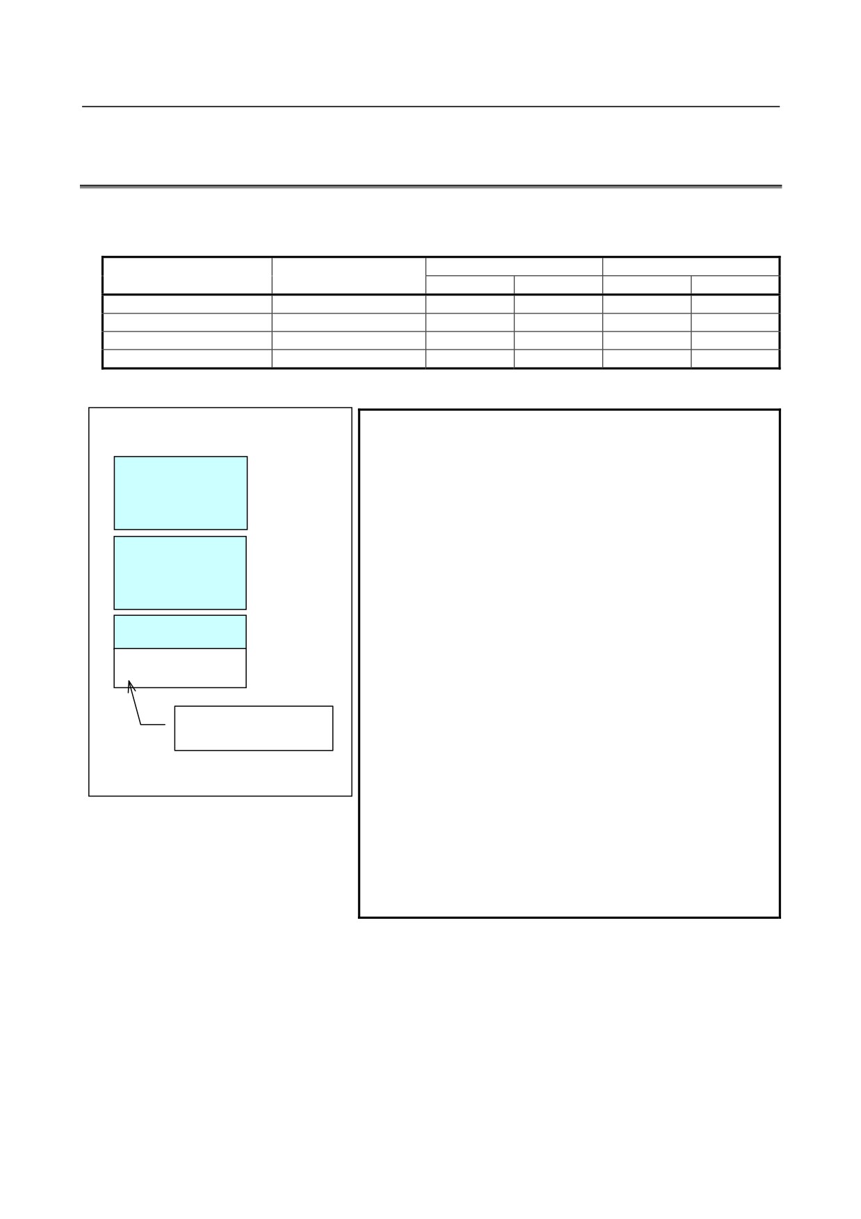
Program O0001
1
The program storage size means the maximum
size of a program if the program is the one and
O0001 ;
First page
N1 G01
;
only program registered.
(Area in use)
2
If more than one program is registered, the
total size of registerable programs reduces for
the following reason.
N100 … ;
Second page
The Series 0i-D/0i Mate-D manage programs
(Area in use)
in page units. The unit of program storage is
managed also in page units. When a program
M30 ;
is created, as many pages as necessary to
Last page
(Area in use)
store the program are secured, and the
program is stored on these pages. Generally,
(Unused area)
the last program storage page has an unused
area (left figure). This unused area cannot be
Unusable for any other
used to store any other program. For the
program
sake of program management, it is regarded as
an area in use.
Example of creating program O0001
The Series 0i-C uses a similar way of
management, but the unit of pages in it differs
from that in the Series 0i-D/0i Mate-D. So, if
more than one program is registered in the
Series 0i-D/0i Mate-D, the total program size of
registerable programs in the Series 0i-D/0i
Mate-D differs from that in the Series 0i-C.
- 144 -
B-64304EN/02
PROGRAMMING
13.PROGRAM CONFIGURATION
13 PROGRAM CONFIGURATION
Overview
-
Main program and subprogram
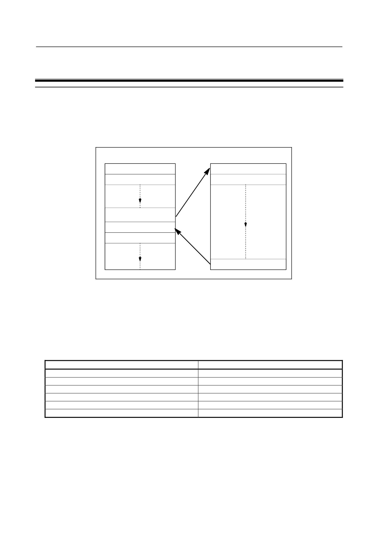
There are two program types, main program and subprogram. Normally, the CNC operates according to
the main program. However, when a command calling a subprogram is encountered in the main
program, control is passed to the subprogram. When a command specifying a return to the main program
is encountered in a subprogram, control is returned to the main program.
Main program
Subprogram
Instruction 1
Instruction 1’
Instruction 2
Instruction 2’
Follow the direction of the
subprogram
Instruction n
Instruction n+1
Return to the main program
Fig. 13 (a) Main program and Subprogram
The CNC memory can hold 400 main programs and subprograms (800 main programs and subprograms
for T series 2-path systems). A main program can be selected from the stored main programs to operate
the machine. See III-9 or III-10.4 for the methods of registering and selecting programs.
-
Program components
A program consists of the following components:
Table 13 (a) Program components
Components
Descriptions
Program code start
Symbol indicating the start of a program file
Leader section
Used for the title of a program file, etc.
Program start
Symbol indicating the start of a program
Program section
Commands for machining
Comment section
Comments or directions for the operator
Program code end
Symbol indicating the end of a program file
- 145 -
13.PROGRAM CONFIGURATION PROGRAMMING
B-64304EN/02
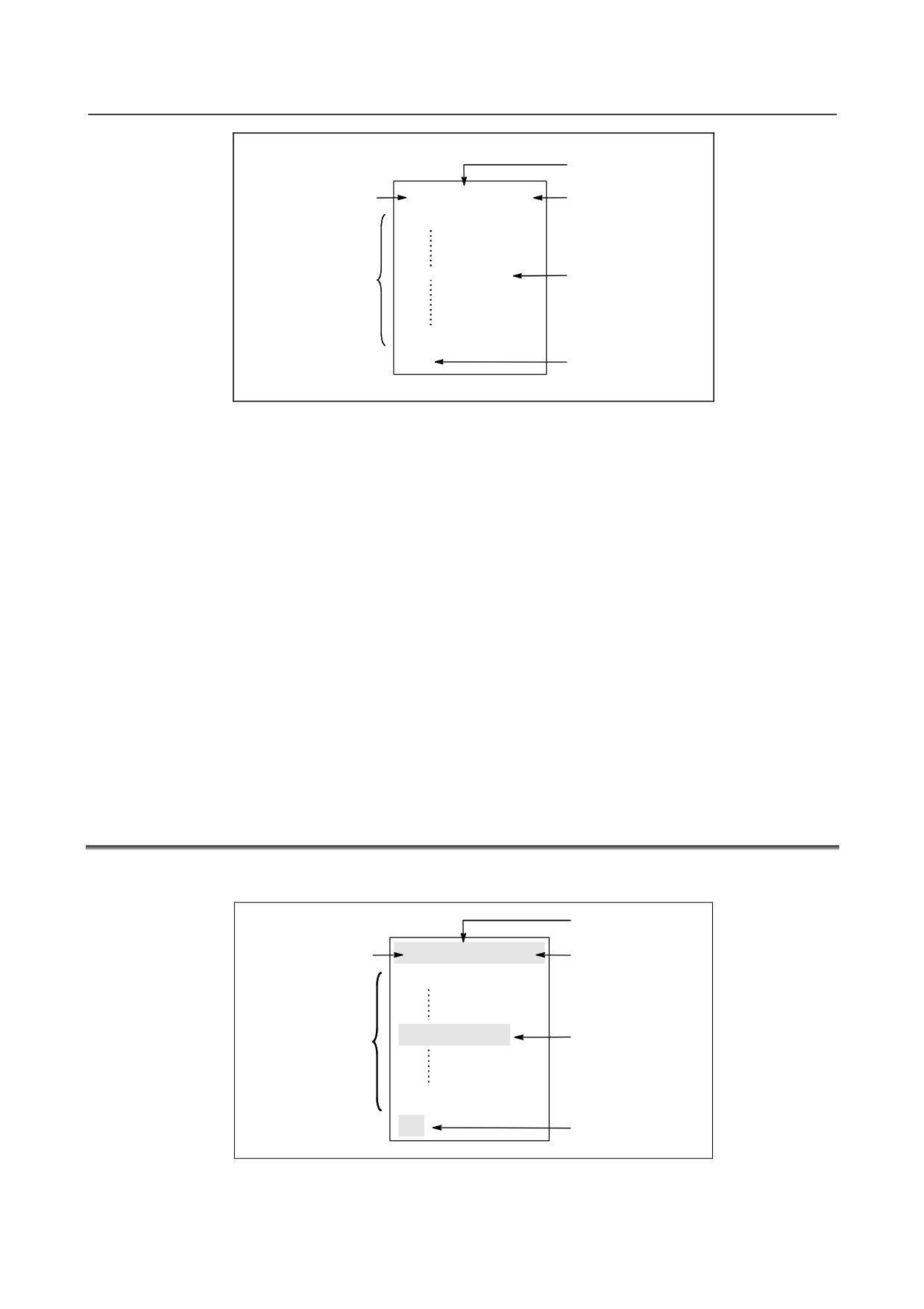
Leader section
Program code start
% TITLE
;
Program start
O0001 ;
(COMMENT)
Program section
Comment section
M30 ;
%
Program code end
Fig. 13 (b) Program configuration
-
Program section configuration
A program section consists of several blocks. A program section starts with a program number and ends
with a program end code.
Program section configuration Program section
Program number
O0001 ;
Block 1
N1 G91 G00 X120.0 Y80.0 ;
Block 2
N2 G43 Z-32.0 H01 ;
:
:
Block n
Nn Z0 ;
Program end
M30 ;
A block contains information necessary for machining, such as a move command or coolant on/off
command. Specifying a slash (/) at the start of a block disables the execution of some blocks (see
"optional block skip" in II-13.2).
13.1 PROGRAM COMPONENTS OTHER THAN PROGRAM
SECTIONS
This section describes program components other than program sections. See II-13.2 for a program
section.
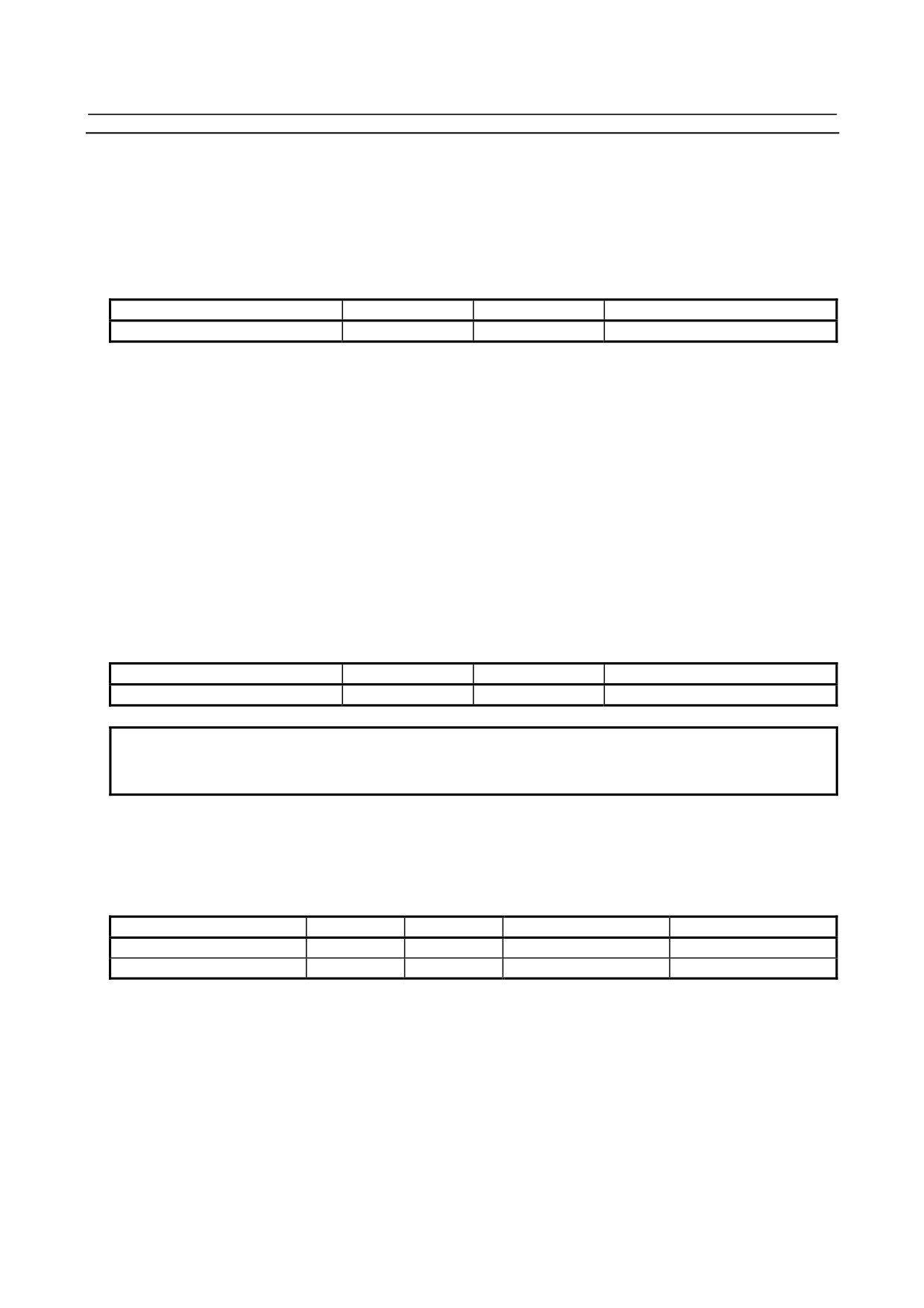
Leader section
Program code start
% TITLE
;
Program start
O0001 ;
(COMMENT)
Comment section
Program section
M30 ;
%
Program code end
Fig. 13.1 (a) Program configuration
- 146 -
B-64304EN/02
PROGRAMMING
13.PROGRAM CONFIGURATION
Explanation
-
Program code start
The program code start indicates the start of a file that contains NC programs.
The mark is not required when programs are entered using ordinary personal computers. The mark is not
displayed on the screen. However, if the file is output, the mark is automatically output at the start of the
file.
Table 13.1 (a) Code of a program code start
Name
ISO code
EIA code
Notation in this manual
Program code start
%
ER
%
-
Leader section
Data entered before the programs in a file constitutes a leader section.
When machining is started, the label skip state is usually set by turning on the power or resetting the
system. In the label skip state, all information is ignored until the first end-of-block code is read. When
a file is read into the CNC unit from an I/O device, leader sections are skipped by the label skip function.
A leader section generally contains information such as a file header. When skipping the leader section, it
is possible to enter any code other than EOB because a TV parity check is not performed.
-
Program start
The program start code is to be entered immediately after a leader section, that is, immediately before a
program section.
This code indicates the start of a program, and is always required to disable the label skip function.
With ordinary personal computers, this code can be entered by pressing the return key.
Table 13.1 (b) Code of a program start
Name
ISO code
EIA code
Notation in this manual
Program start
LF
CR
;
NOTE
If one file contains multiple programs, the EOB code for label skip operation
must not appear before a second or subsequent program number.
-
Comment section
Any information enclosed by the control-out and control-in codes is regarded as a comment.
The user can enter a header, comments, directions to the operator, etc. in a comment section.
Table 13.1 (c) Codes of a control-in and a control-out
Name
ISO code
EIA code
Notation in this manual
Meaning
Control-out
(
2-4-5
(
Start of comment section
Control-in
)
2-4-7
)
End of comment section
When a program is read into memory for memory operation, comment sections, if any, are not ignored
but are also read into memory. Note, however, that codes other than those listed in the code table in
Appendix A are ignored, and thus are not read into memory.
When data in memory is output on external I/O device (See III-8), the comment sections are also output.
When a program is displayed on the screen, its comment sections are also displayed. However, those
codes that were ignored when read into memory are not output or displayed.
During memory operation or DNC operation, all comment sections are ignored.
The TV check function can be used for a comment section by setting bit 1 (CTV) of parameter No. 0100.
- 147 -
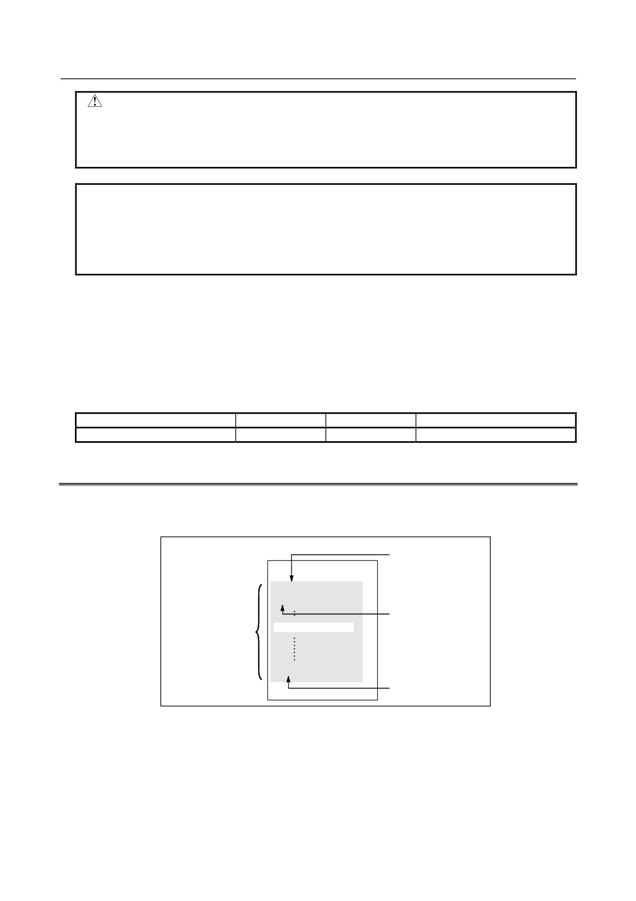
13.PROGRAM CONFIGURATION PROGRAMMING
B-64304EN/02
CAUTION
If a long comment section appears in the middle of a program section, a move
along an axis may be suspended for a long time because of such a comment
section. So a comment section should be placed where movement suspension
may occur or no movement is involved.
NOTE
1 If only a control-in code is read with no matching control-out code, the read
control-in code is ignored.
2 The following codes cannot be used in the comment section:
- EOB
- % (ER for EIA)
-
Program code end
A program code end is to be placed at the end of a file containing NC programs.
If programs are entered using the automatic programming system, the mark need not be entered.
The mark is not displayed on the screen. However, when a file is output, the mark is automatically output
at the end of the file.
If an attempt is made to execute % when M02 or M30 is not placed at the end of the program, the alarm
PS5010 is occurred.
Table 13.1 (d) Code of a program code end
Name
ISO code
EIA code
Notation in this manual
Program code end
%
ER
%
13.2 PROGRAM SECTION CONFIGURATION
This section describes elements of a program section. See II-13.1 for program components other than
program sections.
Program number
%
TITLE ;
O0001 ;
N1 ... ;
Sequence number
(COMMENT)
Program section
M30 ;
%
Program end
Fig. 13.2 (a) Program configuration
-
Program number
A program number consisting of address O followed by a four-digit number is assigned to each program
at the beginning registered in memory to identify the program. When the 8-digit number function is
selected, the program number consists of eight digits.
In ISO code, the colon ( : ) can be used instead of O.
When no program number is specified at the start of a program, the sequence number (N
) at the start of
the program is regarded as its program number.
- 148 -
B-64304EN/02
PROGRAMMING
13.PROGRAM CONFIGURATION
If a five-digit sequence number is used, the lower four digits are registered as a program number. If the
lower four digits are all 0, the program number registered immediately before added to 1 is registered as a
program number. Note, however, that N0 cannot be used for a program number.
If there is no program number or sequence number at the start of a program, a program number must be
specified using the MDI panel when the program is stored in memory (See III-8.2 or III-9.1)
NOTE
Program numbers 8000 to 9999 may be used by machine tool builders, and the
user may not be able to use these numbers.
-
Sequence number and block
A program consists of several commands. One command unit is called a block. One block is separated
from another with an EOB of end of block code.
Table 13.2 (a) EOB code
Name
ISO code
EIA code
Notation in this manual
End of block (EOB)
LF
CR
;
At the head of a block, a sequence number consisting of address N followed by a number not longer than
five digits (1 to 99999) can be placed. Sequence numbers can be specified in a random order, and any
numbers can be skipped. Sequence numbers may be specified for all blocks or only for desired blocks
of the program. In general, however, it is convenient to assign sequence numbers in ascending order in
phase with the machining steps (for example, when a new tool is used by tool replacement, and
machining proceeds to a new surface with table indexing.)
N300 X200.0 Z300.0 ; A sequence number is underlined.
Fig. 13.2 (b) Sequence number and block (example)
NOTE
N0 must not be used for the reason of file compatibility with other CNC systems.
Program number 0 cannot be used. So 0 must not be used for a sequence
number regarded as a program number.
-
TV check (Vertical parity check)
A parity check is made for each block of input data. If the number of characters in one block (starting
with the code immediately after an EOB and ending with the next EOB) is odd, a P/S alarm (No.002) is
output.
No TV check is made only for those parts that are skipped by the label skip function. Bit 1 (CTV) of
parameter No. 0100 is used to specify whether comments enclosed in parentheses are counted as
characters during TV check. The TV check function can be enabled or disabled by setting on the MDI
unit (See III-12.3.1.).
-
Block configuration (word and address)
A block consists of one or more words. A word consists of an address followed by a number some
digits long. (The plus sign (+) or minus sign (-) may be prefixed to a number.)
For an address, one of the letters (A to Z) is used ; an address defines the meaning of a number that
follows the address.
Word = Address + number (Example : X-1000)
Table 13.2 (b) indicates the usable addresses and their meanings.
The same address may have different meanings, depending on the preparatory function specification.
- 149 -
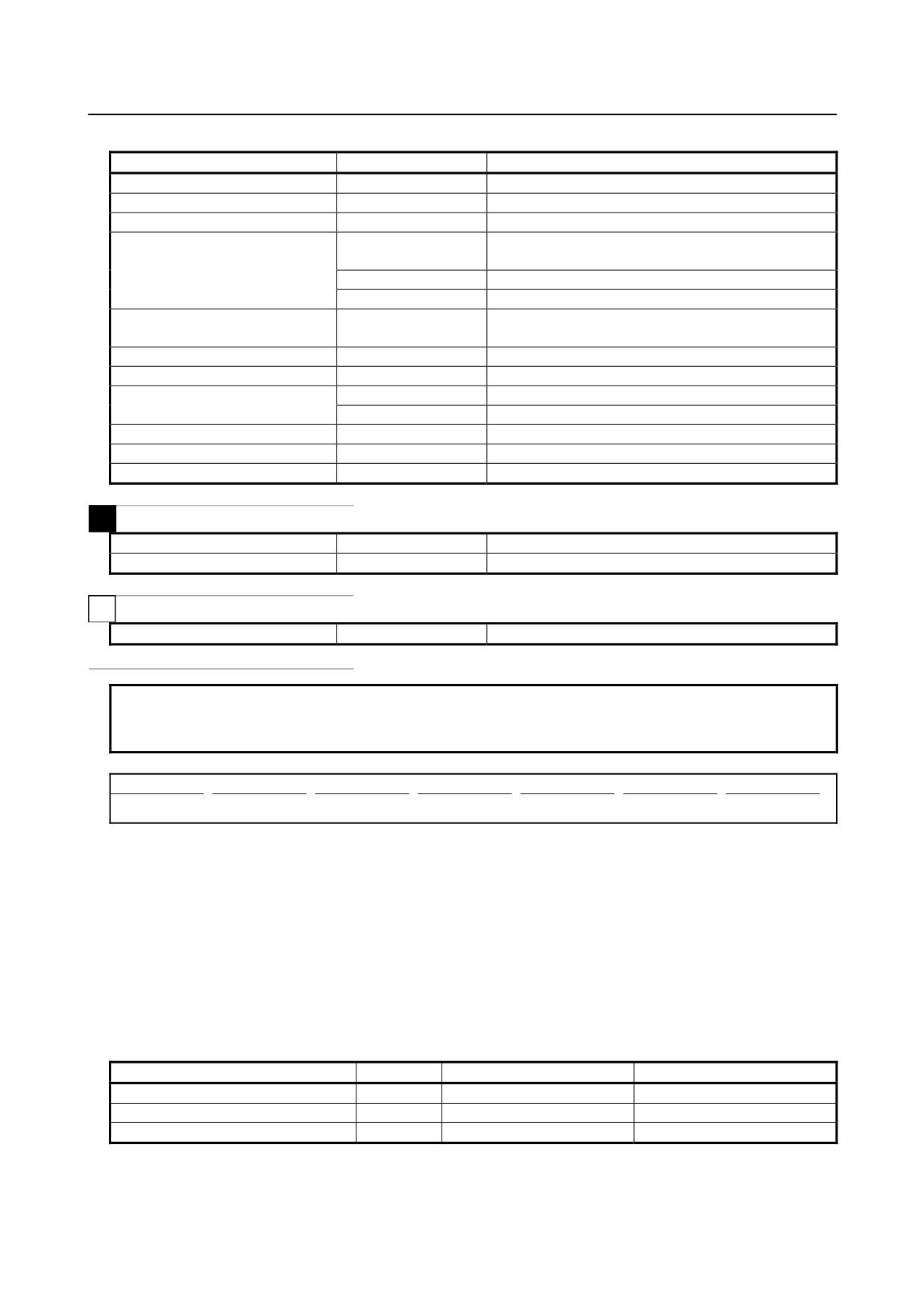
13.PROGRAM CONFIGURATION PROGRAMMING
B-64304EN/02
Table 13.2 (b) Major functions and addresses
Function
Address
Meaning
Program number
O(*)
Program number
Sequence number
N
Sequence number
Preparatory function
G
Specifies a motion mode (linear, arc, etc.)
X, Y, Z, U, V, W, A, B,
Coordinate axis move command
C
Dimension word
I, J, K
Coordinate of the arc center
R
Arc radius
Rate of feed per minute,
Feed function
F
Rate of feed per revolution
Spindle speed function
S
Spindle speed
Tool function
T
Tool number
M
On/off control on the machine tool
Auxiliary function
B
Table indexing, etc.
Program number designation
P
Subprogram number
Number of repetitions
P, L
Number of subprogram repetitions
Parameter
P, Q
Canned cycle parameter
M
Offset number
D, H
Offset number
Dwell
P, X
Dwell time
T
Dwell
P, X, U
Dwell time
NOTE
(*) In ISO code, the colon ( : ) can also be used as the address of a program
number.
N_
G_
X_ Y_
F_
S_
T_
M_
;
Sequence number
Preparatory
Dimension word
Feed-function
Spindle speed
Tool function
Auxiliary function
function
function
Fig. 13.2 (c)
1 block (example)
-
Major addresses and ranges of command values
Major addresses and the ranges of values specified for the addresses are shown below. Note that these
figures represent limits on the CNC side, which are totally different from limits on the machine tool side.
For example, the CNC allows a tool to traverse up to about 100 m (in millimeter input) along the X axis.
However, an actual stroke along the X axis may be limited to 2 m for a specific machine tool.
Similarly, the CNC may be able to control a cutting feedrate of up to 240 m/min, but the machine tool
may not allow more than 3 m/min. When developing a program, the user should carefully read the
manuals of the machine tool as well as this manual to be familiar with the restrictions on programming.
Table 13.2 (c) Major addresses and ranges of command values
Function
Address
Input in mm
Input in inch
Program number
O (*1)
1 to 9999
1 to 9999
Sequence number
N
1 to 99999
1 to 99999
Preparatory function
G
0 to 9999
0 to 9999
- 150 -
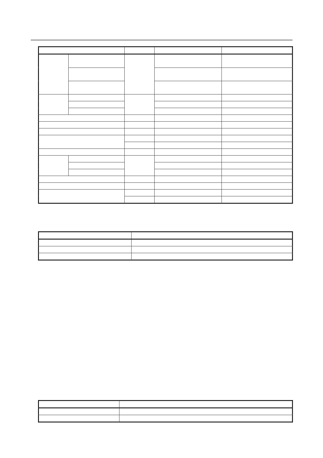
B-64304EN/02
PROGRAMMING
13.PROGRAM CONFIGURATION
Function
Address
Input in mm
Input in inch
±999999.99 mm
±99999.999 inch(*2)
Increment system IS-A
±999999.99 deg
±999999.99 deg
X,Y,Z,U,V,
Dimension
±999999.999 mm
±99999.9999 inch(*2)
Increment system IS-B
W,A,B,C,I,
word
±999999.999 deg
±999999.999 deg
J,K,R
±99999.9999 mm
±9999.99999 inch(*2)
Increment system IS-C
±99999.9999 deg
±99999.9999 deg
Increment system IS-A
0.01 to 999000.00 mm/min
0.001 to 96000.000 inch/min
Feed per
Increment system IS-B
F
0.001 to 999000.000 mm/min
0.0001 to 9600.0000 inch/min
minute
Increment system IS-C
0.0001 to 99999.9999 mm/min
0.00001 to 4000.00000 inch/min
Feed per revolution
F
0.0001 to 500.0000 mm/rev
0.000001 to 9.999999 inch/rev
Spindle speed function
S (*3)
0 to 99999
0 to 99999
Tool function
T (*3)
0 to 99999999
0 to 99999999
M (*3)
0 to 99999999
0 to 99999999
Auxiliary function
B (*3)
0 to 99999999
0 to 99999999
Offset number (M series only)
H, D
0 to 400
0 to 400
Increment system IS-A
X,
0 to 999999.99 sec
0 to 999999.99 sec
Dwell
Increment system IS-B
U (T series
0 to 99999.999 sec
0 to 99999.999 sec
Increment system IS-C
only)
0 to 9999.9999 sec
0 to 9999.9999 sec
Dwell
P
1 to 99999999
1 to 99999999
Designation of a program number
P
1 to 9999
1 to 9999
L
1 to 99999999
1 to 99999999
Number of subprogram repetitions
P
0 to 9999
0 to 9999
*1 In ISO code, the colon ( : ) can also be used as the address of a program number.
*2 For inch input/millimeter machines, the maximum specifiable range of dimension words is as
follows:
Increment system
Maximum specifiable range
IS-A
±39370.078 inch
IS-B
±39370.0787 inch
IS-C
±3937.00787 inch
*3 The maximum value of addresses M, T, and B is 99999999(8 digits). The maximum value of address
S is 99999(5 digits). Note that, however, values longer than the permissible number of digits set in
parameter No. 3030 to 3033 cannot be specified. The values and uses for some codes are limited by
parameter setting. (For example, some M codes are not buffered.) For details, refer to the parameter
manual.
-
Optional block skip
When a slash followed by a number (/n (n=1 to 9)) is specified at the head of a block, and optional block
skip signals BDT1 to BDT9 are set to 1 during automatic operation, the information (/n to the end of the
block (EOB)) contained in the block for which /n corresponding to signal BDTn is specified is ignored.
Example 1)
/2 N123 X100.0 Y200.0 ;
Example 2)
//3 N123 X100.0 Y200.0 ;
→ Incorrect
/1 /3 N123 X100.0 Y200.0 ; → Correct
Input signal and program code
Input signal
Start code to be ignored
BDT1
/ or /1(NOTE)
BDT2
/2
- 151 -
13.PROGRAM CONFIGURATION PROGRAMMING
B-64304EN/02
Input signal
Start code to be ignored
BDT3
/3
BDT4
/4
BDT5
/5
BDT6
/6
BDT7
/7
BDT8
/8
BDT9
/9
NOTE
1 Number 1 for /1 can be omitted. However, when two or more optional block
skips are specified for one block, number 1 for /1 cannot be omitted.
2 Depending on the machine tool, all optional block skip signals (1 to 9) may not
be usable. Refer to manuals of the machine tool builder to find which switches
are usable.
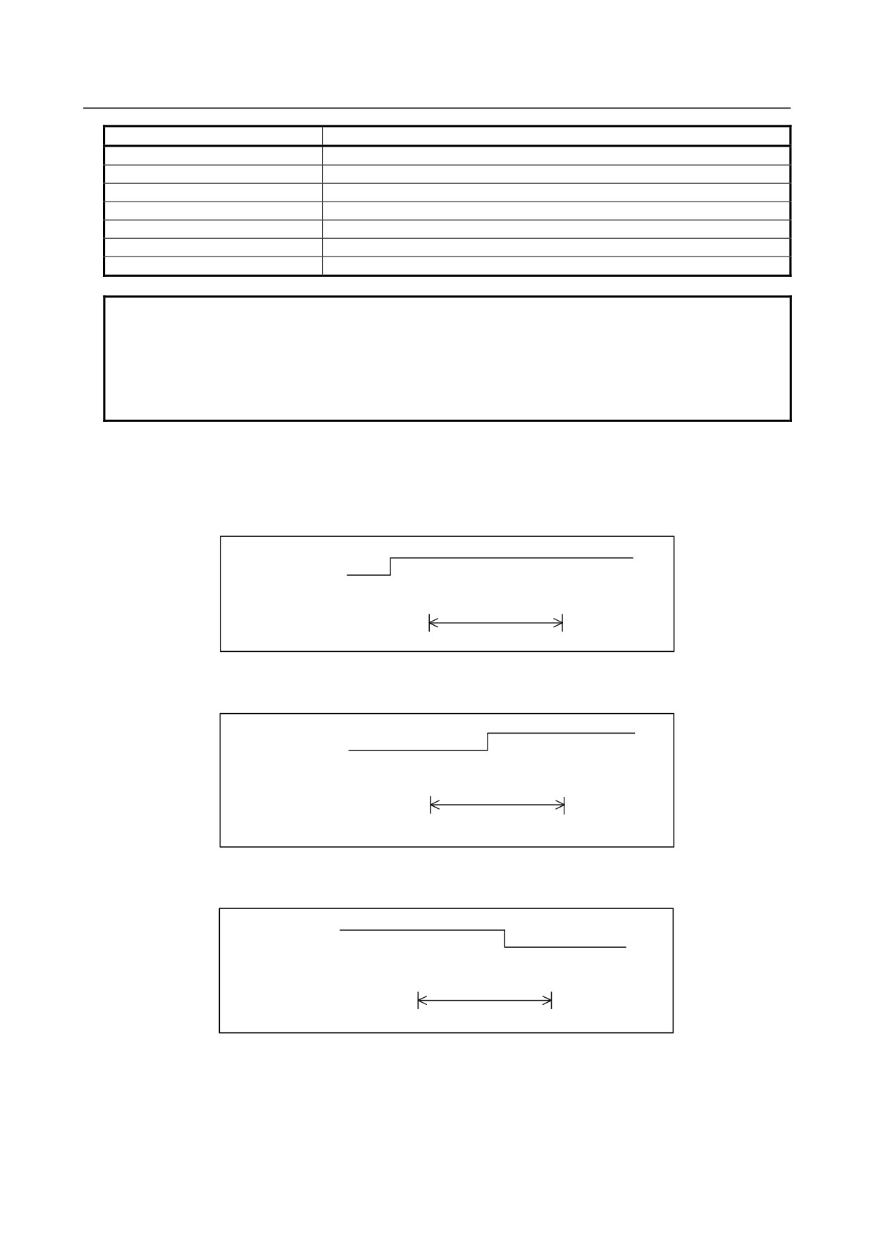
The following shows the relationship between the timing at which optional block skip signals BDT1 to
BDT9 are set to 1 and the range of information to be ignored.
1.
When the signal BDTn is set to 1 before the CNC starts reading a block that contains /n, the block is
ignored.
BDTn "1"
"0"
Read by CNC → . . .
; /n N123 X100. Y200. ;N234
This range of information is ignored.
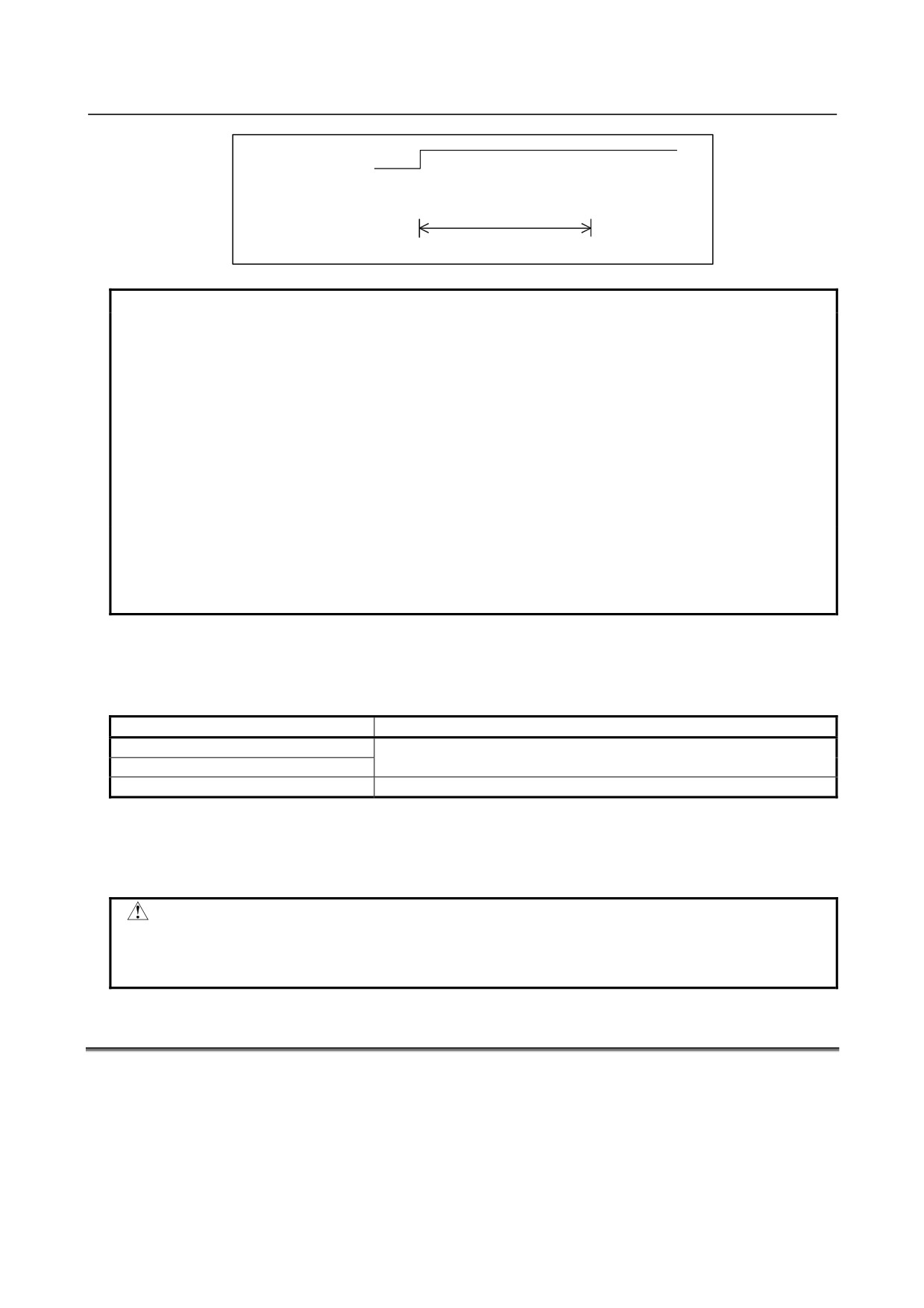
2.
When the signal BDTn is set to 1 while the CNC is reading a block that contains /n, the block is not
ignored.
BDTn "1"
"0"
Read by CNC → . . .
; /n N123 X100. Y200. ; N234
This range of information is not ignored.
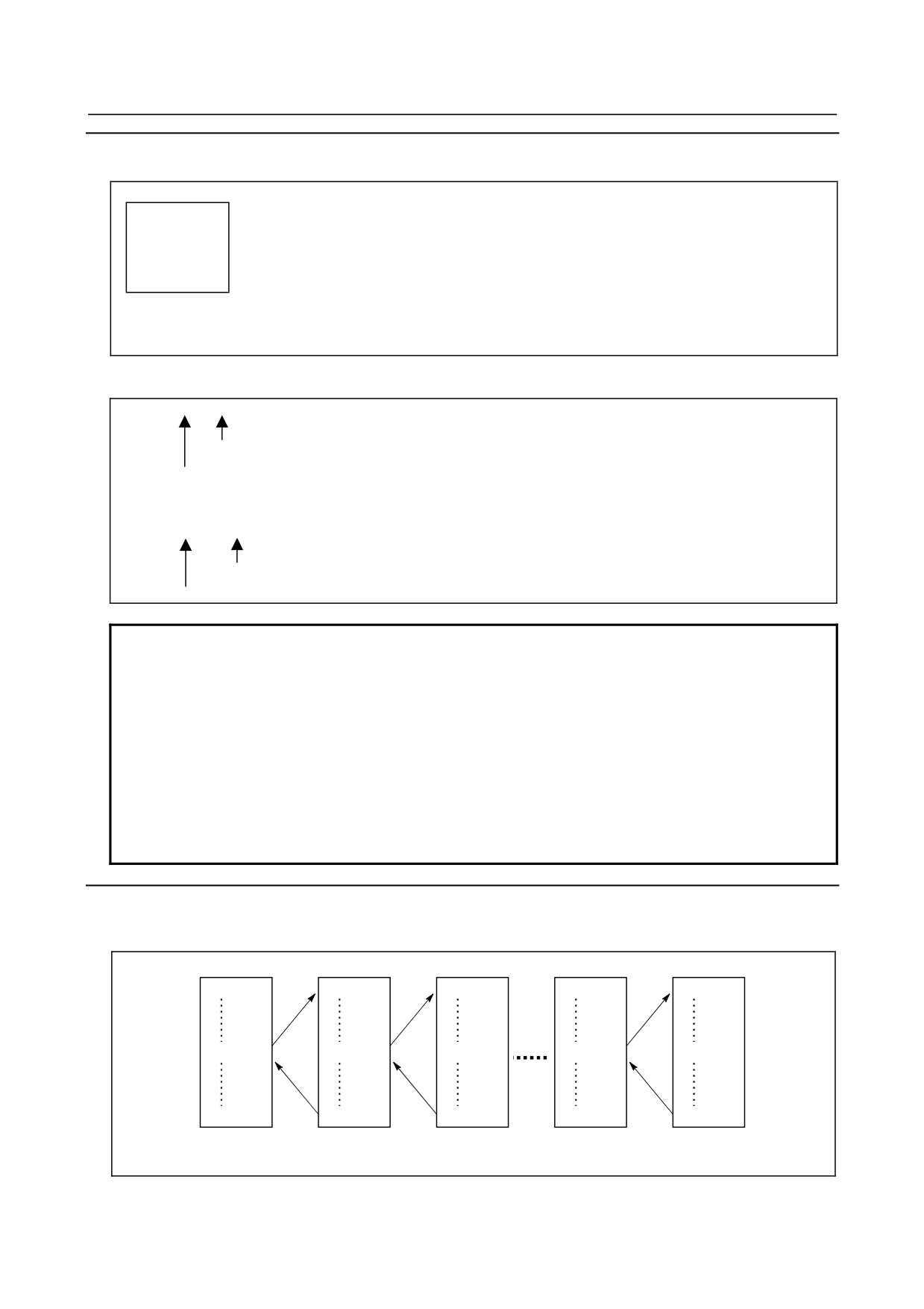
3.
When the signal BDTn is set to 0 while the CNC is reading a block that contains /n, the block is
ignored.
BDTn "1"
"0"
Read by CNC → . . .
; /n N123 X100. Y200.; N234
This range of information is ignored.
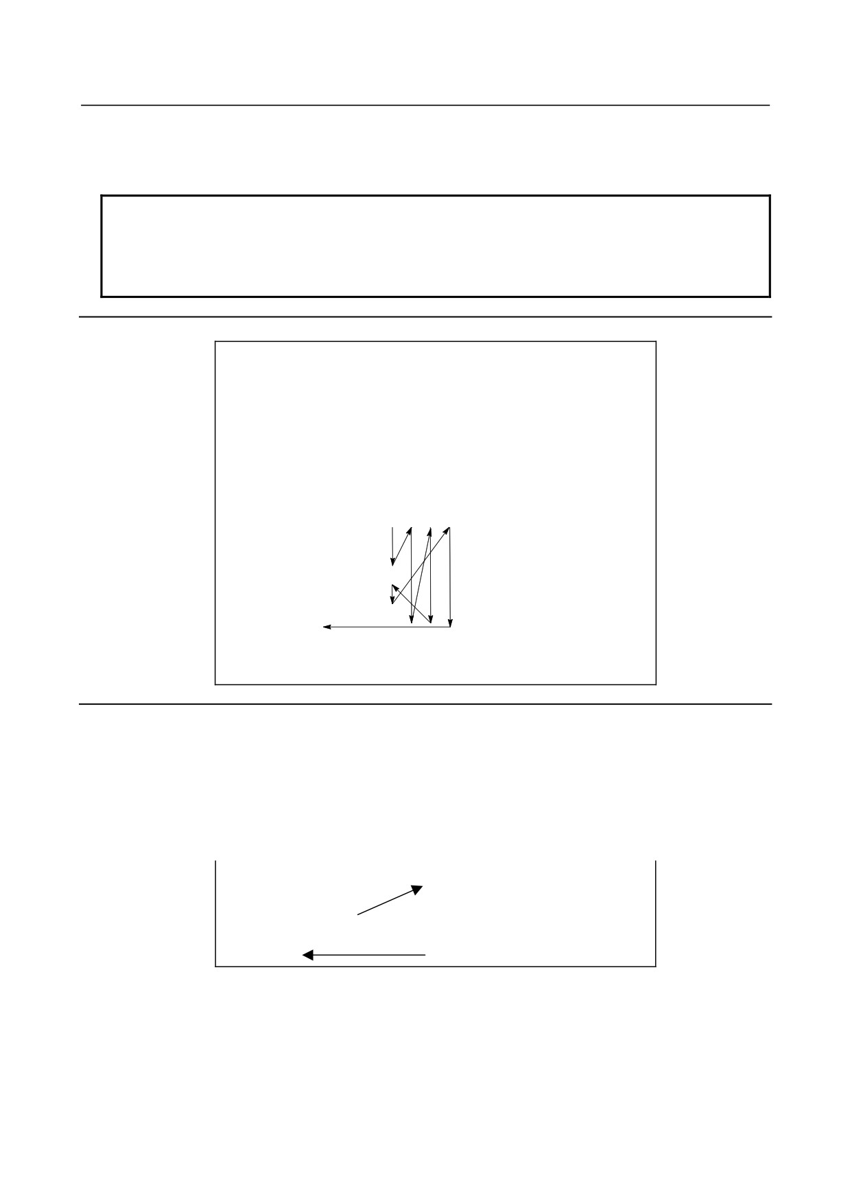
4.
Two or more optional block skips can be specified in one block. When the signal corresponding to
any of the specified skips is set to 1, the block is ignored.
- 152 -
B-64304EN/02
PROGRAMMING
13.PROGRAM CONFIGURATION
BDT3
"1"
"0"
Read by CNC → . . . ; /1 /3 /5 N123 X100. Y200. ; N234
This range of information is ignored.
NOTE
1 This function is not used when a program is registered in memory. A block
containing / is registered in memory regardless of the statuses of optional block
skip signals. When a program in memory is also output regardless of the
statuses of optional block skip signals.
In addition, the optional block skip function is enabled during a search for a
sequence number.
2 Position of a slash
A slash (/) must be specified at the head of a block. If a slash is placed
elsewhere, the information from the slash to immediately before the EOB code is
ignored.
3 TV and TH check
When the optional block skip signal is set to 1, TH and TV checks are made for
the skipped portions in the same way as when the optional block skip signal is
set to 0.
-
Program end
The end of a program is indicated by programming one of the following codes at the end of the program:
Table 13.2 (d) Code of a program end
Code
Meaning usage
M02
For main program
M30
M99
For subprogram
If one of the program end codes is executed in program execution, the CNC terminates the execution of
the program, and the reset state is set. When the subprogram end code is executed, control returns to the
program that called the subprogram.
CAUTION
A block containing an optional block skip code such as /M02 ; , /M30 ; , or /M99 ;
is not regarded as the end of a program.
(see "Optional block skip".)
13.3 SUBPROGRAM (M98, M99)
If a program contains a fixed sequence or frequently repeated pattern, such a sequence or pattern can be
stored as a subprogram in memory to simplify the program.
A subprogram can be called from the main program.
A called subprogram can also call another subprogram.
- 153 -
13.PROGRAM CONFIGURATION PROGRAMMING
B-64304EN/02
Format
-
Subprogram configuration
One subprogram
Oxxxx ;
Subprogram number (or the colon (:) optionally in the case of ISO)
:
Program end
M99;
M99 need not constitute a separate block as indicated below.
Example) X100.0 Y100.0 M99 ;
-
Subprogram call
M98 Pxxxx xxxx ;
Subprogram number
Number of times the subprogram is called repeatedly
or
M98 Pxxxx Lxxxxxxxx ;
Number of times the subprogram is called repeatedly
Subprogram number
NOTE
1 When a subprogram is call repeatedly (P8-digit number), the number of digits of
the subprogram number is less than 4, pad the upper digit(s) with 0.
Example)
P100100:
Call subprogram No. 100 ten times.
P50001:
Call subprogram No. 1 five times.
2 When the repeat count is omitted, a repeat count of 1 is assumed.
In this case, it is not necessary to adjust the subprogram number length to 4
digits as described in Item 1 above.
3 When a subprogram is call repeatedly (P8-digit number), do not specify address
L in the same block.
Explanation
When the main program calls a subprogram, it is regarded as a one-level subprogram call. Thus,
subprogram calls can be nested up to ten levels as shown below.
Main program
Subprogram
Subprogram
Subprogram
Subprogram
O0001 ;
O0010 ;
O0020 ;
O0090 ;
O0100 ;
M98P0010 ;
M98P0020 ;
M98P0030 ;
M98P0100 ;
M30 ;
M99 ;
M99 ;
M99 ;
M99 ;
(One-level
(Two-level
(Nine-level
(Ten-level
nesting)
nesting)
nesting)
nesting)
- 154 -
B-64304EN/02
PROGRAMMING
13.PROGRAM CONFIGURATION
A single call command can repeatedly call a subprogram up to 99999999 times. For compatibility with
automatic programming systems, in the first block, Nxxxxx can be used instead of a subprogram number
that follows O (or :). A sequence number after N is registered as a subprogram number.
NOTE
1 The M98 and M99 code signal and strobe signal are not output to the machine
tool.
2 If the subprogram number specified by address P cannot be found, an alarm
PS0078 is output.
Example
-
M98 P51002 ;
This command specifies "Call the subprogram (number 1002) five times in
succession." A subprogram call command (M98P_) can be specified in the
same block as a move command.
-
X1000.0 M98 P1200 ;
This example calls the subprogram (number 1200) after an X axis
movement.
-
Execution sequence of subprograms called from a main program
Main program
Subprogram
1
2
3
N0010 . . . ;
O1010 . . . ;
N0020 . . . ;
N1020 . . . ;
N0030 M98 P21010 ;
N1030 . . . ;
N0040 . . . ;
N1040 . . . ;
N0050 M98 P1010 ;
N1050 . . . ;
N0060 . . . ;
N1060 . . . M99 ;
A subprogram can call another subprogram in the same way as a main
program calls a subprogram.
Special usage
-
Specifying the sequence number for the return destination in the main
program
If P is used to specify a sequence number when a subprogram is terminated, control does not return to the
block after the calling block, but returns to the block with the sequence number specified by P. When
P0 is specified, however, P is ignored. In addition, when the main program is running in a mode other
than memory operation mode, P is ignored.
This method consumes a much longer time than the normal return method to return to the main program.
Main program
Subprogram
N0010 . . . ;
O1010
;
N0020 . . . ;
N1020 . . . ;
N0030 M98 P1010 ;
N1030 . . . ;
N0040 . . . ;
N1040 . . . ;
N0050 . . . ;
N1050 . . . ;
N0060 . . . ;
N1060 . . . M99 P0060 ;
-
Using M99 in the main program
If M99 is executed in a main program, control returns to the start of the main program. For example, M99
can be executed by placing /M99 ; at an appropriate location of the main program and setting the optional
block skip function to off when executing the main program. When M99 is executed, control returns to
the start of the main program, then execution is repeated starting at the head of the main program.
Execution is repeated while the optional block skip function is set to off.
- 155 -