FANUC Series 0i-MODEL D, Series 0i Mate-MODEL D. OPERATOR'S MANUAL - page 7
13.PROGRAM CONFIGURATION PROGRAMMING
B-64304EN/02
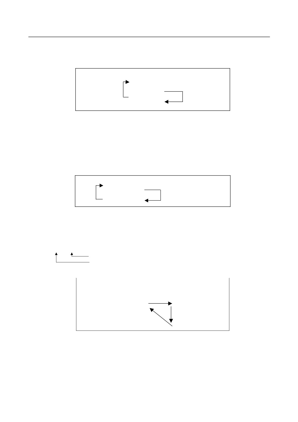
If the optional block skip function is set to on, the /M99 ; block is skipped ; control is passed to the next
block for continued execution.
If/M99Pn ; is specified, control returns not to the start of the main program, but to sequence number n. In
this case, a longer time is required to return to sequence number n.
N0010 . . . ;
N0020 . . . ;
N0030 . . . ;
Optional block skip
N0040 . . . ;
OFF
N0050 . . . ;
Optional block skip
/
N0060 . . . M99 P0030 ;
N0070 . . . ;
ON
N0080 M02 ;
-
Using a subprogram only
A subprogram can be executed just like a main program by searching for the start of the subprogram with
the MDI.
(See III-10.4 for information about search operation.)
In this case, if a block containing M99 is executed, control returns to the start of the subprogram for
repeated execution. If a block containing M99Pn is executed, control returns to the block with sequence
number n in the subprogram for repeated execution. To terminate this program, a block containing /M02 ;
or /M30 ; must be placed at an appropriate location, and the optional block switch must be set to off ; this
switch is to be set to on first.
N1010 . . . ;
N1020 . . . ;
N1030 . . . ;
/
N1040 . . . M02 ;
Optional block skip ON
N1050 M99 P1020 ;
-
Subprogram call with sequence number
Setting bit 0 (SQC) of parameter No. 6005 to 1 can call a specified sequence number in the subprogram
for execution.
In a subprogram call command, specify the letter Q followed by a sequence number to be called after the
letter P for specifying a program number.
M98 Pxxxx Qxxxxx ;
Sequence number
Program number
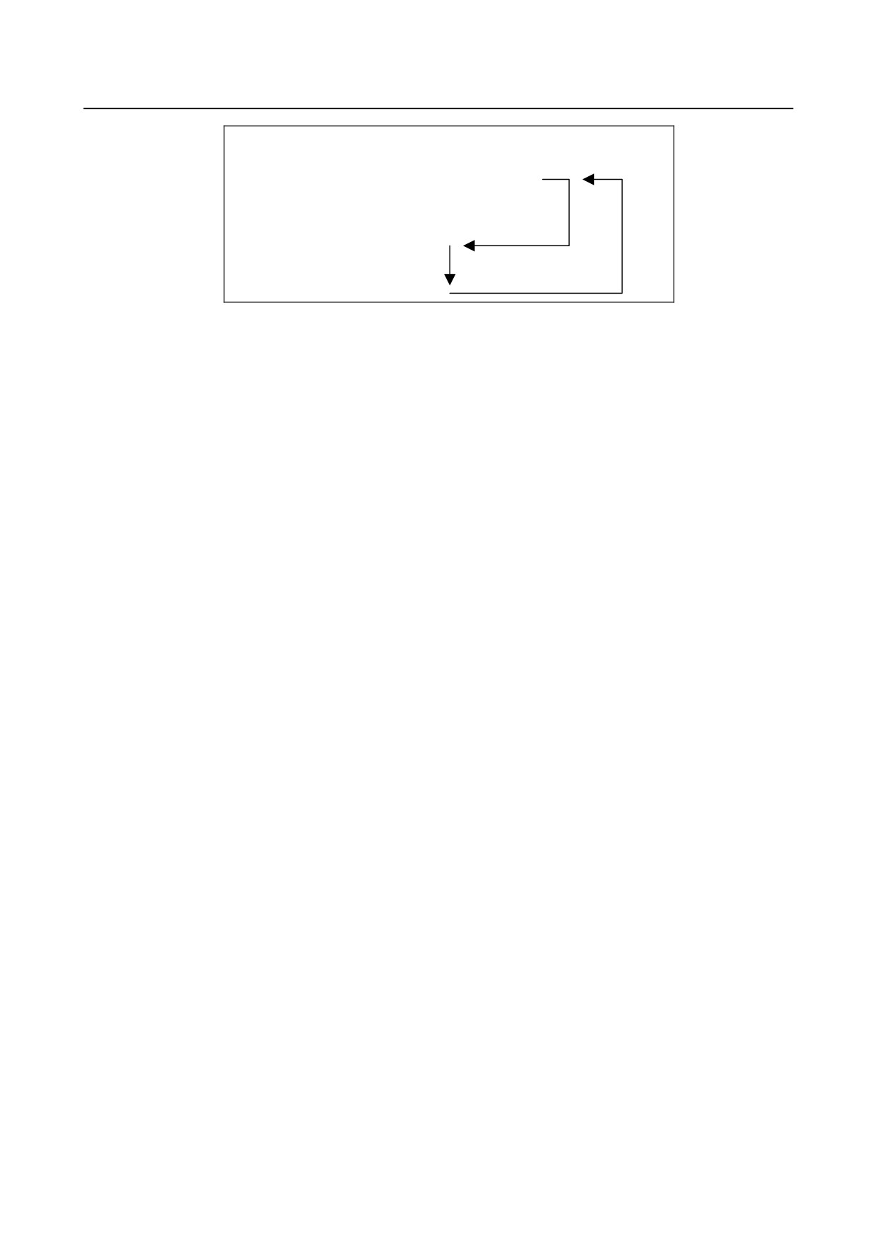
This command causes program execution to start at the called sequence number in the subprogram. If a
repetition count is specified, program execution is repeated from the specified sequence number.
Main program
Sub program
N0010…;
O1010…;
N0020…;
N1020…;
N0030 M98 P1010 Q1030 ;
N1030…;
N0040…;
N1040…;
N0050…;
N1050…;
N0060…;
N1060…M99 ;
This function enables a sequence number in the same program to be called for execution as shown below.
This method, however, requests the programmer to be aware of an allowable call nesting level. If an
attempt is made to exceed the allowable nesting level, alarm PS0077 meaning
“TOO MANY
SUB,MACRO NESTING” is issued.
- 156 -
B-64304EN/02
PROGRAMMING
13.PROGRAM CONFIGURATION
O0001 ;
N0010…;
N0020 M98 (P0001) Q0050 ;
N0030…;
N0040…;
N0050…;
N0060…;
N0070…M99;
For a call within the same program, specification of Pxxxx in a block can be omitted when the block
includes M98.
This function is usable only for subprogram calls by M98; it is unusable for non-M98 calls, such as macro
calls or external subprogram calls based on M198.
- 157 -
14.CUSTOM MACRO
PROGRAMMING
B-64304EN/02
14 CUSTOM MACRO
Although subprograms are useful for repeating the same operation, the custom macro function also allows
use of variables, arithmetic and logic operations, and conditional branches for easy development of
general programs such as pocketing and user-defined canned cycles.
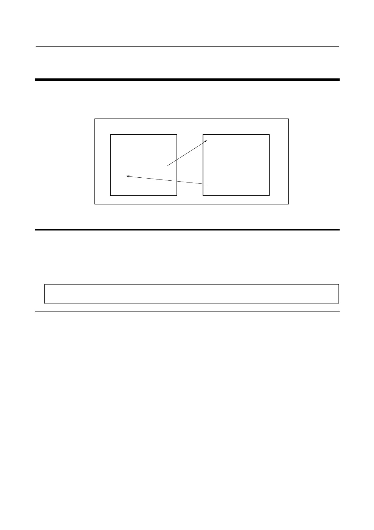
A machining program can call a custom macro with a simple command, just like a subprogram.
Machining program
Custom macro
O0001 ;
O9010 ;
:
#1=#18/2 ;
:
G01 G42 X#1 Y#1 F300 ;
:
02 X#1 Y-#1 R#1 ;
G65 P9010 R50.0 L2 ;
:
:
:
:
:
M30 ;
M99 ;
14.1 VARIABLES
An ordinary machining program specifies a G code and the travel distance directly with a numeric value;
examples are G100 and X100.0.
With a custom macro, numeric values can be specified directly or using a variable number. When a
variable number is used, the variable value can be changed by a program or using operations on the MDI
panel.
#1=#2+100 ;
G01 X#1 F300 ;
Explanation
-
Variable representation
When specifying a variable, specify a number sign (#) followed by a variable number.
#i (i = 1, 2, 3, 4,
)
[Example] #5
#109
#1005
A variable can also be represented as follows using
<expression> described in the section about
arithmetic and logic operation commands.
#[<expression>]
[Example] #[#100]
#[#1001-1]
#[#6/2]
Variable #i shown in the following can be replaced with a variable of #[<expression>].
-
Types of variables
Variables can be classified as local variables, common variables, and system variables according to the
variable number. Each of those variables has its own usage and characteristics. Read-only system
constants are also provided.
- 158 -
B-64304EN/02
PROGRAMMING
14.CUSTOM MACRO
-
Range of variable values
Local and common variables can have a value in the following ranges. If the result of calculation
exceeds the range, an alarm PS0111 is issued.
When bit 0 (F0C) of parameter No.6008 = 0
Maximum value: approx. ±10308
Minimum value: approx. ±10-308
Numeric data handled by a custom macro conforms to the IEEE standard and is handled as a
double-precision real number. An error resulting from operation depends on the precision.
When bit 0 (F0C) of parameter No.6008 = 1
Maximum value: approx. ±1047
Minimum value: approx. ±10-29
-
Local variable (#1-#33)
A local variable is a variable that is used locally in a macro. That is, local variable #i used by a macro
called at a certain time is different from that used by a macro called at another time, regardless of whether
the two macros are the same. Therefore, for example, when macro A calls macro B during multiple calls
or the like, it is impossible for macro B to corrupt a local variable used by macro A by erroneously using
the variable.
A local variable is used to pass arguments. For information on correspondence between arguments and
addresses, see the section about macro calling commands. The initial state of a local variable to which
no arguments are passed is <null> and the user can freely use the variable. The attribute of a local
variable is READ/WRITE enabled.
-
Common variable (#100-#199, #500-#999)
A common variable is shared among the main program, subprograms called by the main program, and
macros while a local variable is used locally in a macro. That is, #i used by a macro is the same as that
used by another macro. Therefore, a resultant common variable obtained by using a macro can be used
by another macro. The attribute of a common variable is basically READ/WRITE enabled. However,
the common variable can be protected (its attribute is set to READ only) by specifying its variable
number using parameters No.6031 and No.6032. A common variable can be freely used by the user
even when its usage is not defined by the system. A total of 600 common variables (#100 to #199 and
#500 to #999) can be used. Common variables #100 to #199 are cleared during power-off, but common
variables #500 to #999 are not cleared during power-off.
-
Write protection of a common variable
Multiple common variables (#500 to #999) can be protected (their attributes are set to READ only) by
setting variable numbers in parameters No.6031 and No.6032. This protection is enabled for both
Input/All Clear by MDI on the macro screen and write operation by a macro program. If the NC
program specifies WRITE operation (used in the left side) for a common program in the set range, an
alarm PS0116 is issued.
-
System variable
A variable whose usage does not vary in the system. The attribute of a system variable is READ only,
WRITE only, or READ/WRITE enabled depending on the nature of a system variable.
-
System constant
A system constant can be referenced as with a variable even though its value is fixed. The attribute of a
system constant is READ only.
-
Omission of the decimal point
When a variable value is defined in a program, the decimal point can be omitted.
[Example]
When #1 = 123; is defined, the actual value of variable #1 is 123.000.
- 159 -
14.CUSTOM MACRO
PROGRAMMING
B-64304EN/02
-
Referencing variables
The value following an address can be replaced with a variable. When programming as <address>#i or
<address>-#i, the variable value or the complement of it is used as the specified value of the address.
[Example] F#33 is the same as F1.5 when #33 = 1.5.
Z-#18 is the same as Z-20.0 when #18 = 20.0.
G#130 is the same as G3 when #130 = 3.0.
A variable cannot be referenced using address/, :, or O and N.
[Example] Programming such as O#27, N#1, or N[#1] is not allowed.
n (n = 1 to 9) in the optional block skip /n cannot be a variable.
A variable number cannot be specified by a direct variable.
[Example] When replacing 5 in #5 with #30, specify #[#30] instead of ##30. No values exceeding the maximum
allowable value for each address can be specified.
[Example] When #140 = 120, G#140 exceeds the maximum allowable value.
When a variable is used as address data, the variable is automatically rounded off to the number of
significant figures of each address or less.
[Example] For a machine with an increment system of 1/1000 mm (IS-B), when #1 = 12.3456, G00 X#1; becomes
G00 X12.346;.
If
<expression>, described later, is used, the value following an address can be replaced with
<expression>.
<address>[<expression>] or <address>-[<expression>]
The program code shown above indicates the value of <expression> or the complement of the value is
used as an address value. Note that a constant with no decimal point, enclosed in brackets ([ ]), is
assumed to have a decimal point at the end.
[Example] X[#24+#18*COS[#1]]
Z-[#18+#26]
-
Undefined variable
When the value of a variable is not defined, such a variable is referred to as a "null" variable. Variables
#0 and #3100 are always null variables. They cannot be written to, but they can be read.
(a) Quotation
When an undefined variable is quotated, the address itself is also ignored.
Original command
G90 X100 Y#1
Equivalent command when #1 = <null>
G90 X100
Equivalent command when #1 = 0
G90 X100 Y0
(b) Definition/replacement, addition, multiplication
When a local variable or common variable is directly replaced with <null>, the result is <null>.
When a system variable is directly replaced with <null> or the result of calculation including <null>
is replaced, a variable value of 0 is assumed.
Original expression (local variable)
#2=#1
#2=#1*5
#2=#1+#1
Replacement result (when #1 = <null>)
<null>
0
0
Replacement result (when #1 = 0)
0
0
0
Original expression (common variable)
#100=#1
#100=#1*5
#100=#1+#1
Replacement result (when #1 = <null>)
<null>
0
0
Replacement result (when #1 = 0)
0
0
0
Original expression (system variable)
#2001=#1
#2001=#1*5
#2001=#1+#1
Replacement result (when #1 = <null>)
0
0
0
Replacement result (when #1 = 0)
0
0
0
- 160 -
B-64304EN/02
PROGRAMMING
14.CUSTOM MACRO
(c) Comparison
<null> differs from 0 only for EQ and NE.
<null> is equal to 0 for GE, GT, LE, and LT.
•
When <null> is assigned to #1
Conditional
#1 EQ #0
#1 NE 0
#1 GE #0
#1 GT 0
#1 LE #0
#1 LT 0
expression
Not
Not
Evaluation
Established
Established
Established
Established
established
established
result
(true)
(true)
(true)
(true)
(false)
(false)
•
When 0 is assigned to #1
Conditional
#1 EQ #0
#1 NE 0
#1 GE #0
#1 GT 0
#1 LE #0
#1 LT 0
expression
Not
Not
Not
Not
Evaluation
Established
Established
established
established
established
established
result
(true)
(true)
(false)
(false)
(false)
(false)
-
Specifying a system variable (constant) by its name
A system variable (constant) is specified by its variable number, but it can also be specified by its
predetermined system variable (constant) name. A system variable (constant) name begins with an
underscore (_), followed by up to seven uppercase letters, numerics, or underscores. For axis-dependent
variables
(such as coordinates) or variables having a lot of data of similar types
(such as tool
compensation), subscript [n] (n: integer) can be used to specify values. In this case, n can be specified in
<expression> format (calculation format).
The command format must be specified in [#system-variable-name] format, as shown below.
[#_DATE]
[Example]
#101= [#_DATE] ;
:
#3011 (year/month/date) is read off and assigned to #101.
#102= [#_TIME] ;
:
#3012 (hour/minute/second) is read off and assigned to #102.
#103=[#_ABSMT[1]] ;
:
#5021 (machine coordinate value of the 1st axis) is read off and assigned to #103.
#104=[#_ABSKP[#500*2]] ; : #506x (skip position of [#500*2]th axis) is read off and assigned to #104.
If a value other than an integer is specified for subscript n, a variable value is referenced, assuming that
the fractional portion is rounded off.
[Example]
[#_ABSIO[1.4999999]]
: This value is assumed to be [#_ABSIO[1]], that is, #5001.
[#_ABSIO[1.5000000]]
: This value is assumed to be [#_ABSIO[2]], that is, #5002.
NOTE
1 When the specified variable name is not registered, an alarm PS1098 is issued.
2 When a negative or other invalid subscript is specified, an alarm PS1099 is
issued.
-
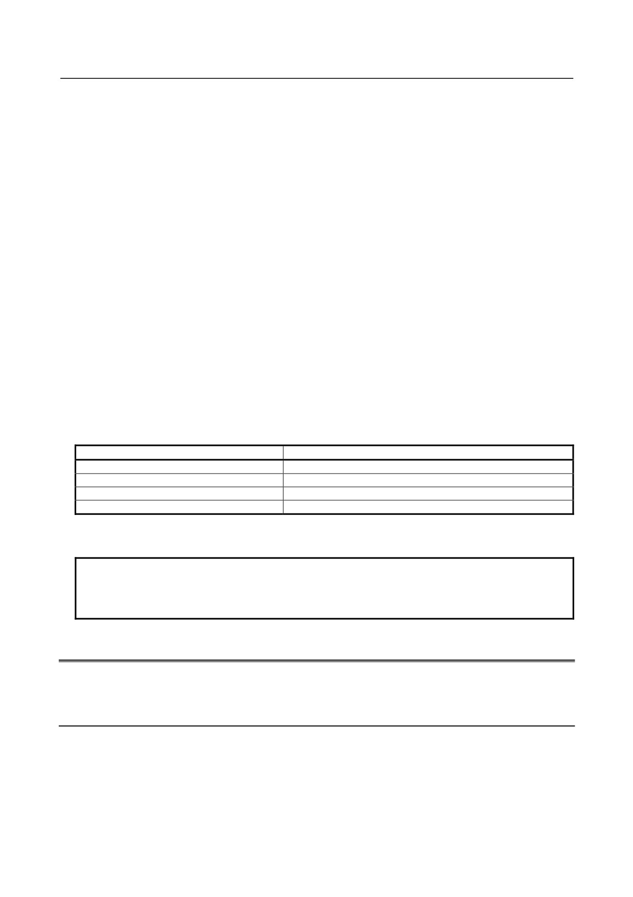
System constant #0, #3100-#3102 (Attribute: R)
Constants used as fixed values in the system can be used as system variables. Such constants are called
system constants. The system constants provided are shown below.
Constant number
Constant name
Description
#0, #3100
[#_EMPTY]
Null
#3101
[#_PI]
Circular constant π= 3.14159265358979323846
#3102
[#_E]
Base of natural logarithm e= 2.71828182845904523536
- 161 -
14.CUSTOM MACRO
PROGRAMMING
B-64304EN/02
-
Specifying a common variable by its name
Specifying a variable name set by the SETVN command described later allows reading from or writing to
a common variable.
The command must be specified in the form [#common-variable-name] such as [#VAR500].
[Example]
X[#POS1] Y[#POS2] ;
: Specifying a position by the variable name
[#POS1] = #100+#101 ;
: Executing a assignment statement by the variable name
#[100+[#ABS]] = 500 ;
: Same as above (by a variable number)
#500 = [1000+[#POS2]*10] ;
: Reading a variable by a variable name
-
Setting and specifying the name of a common variable (SETVN)
For the 50 common variables, #500 to #549, a name of up to eight characters can be specified by using a
command as shown below.
SETVN n [VAR500, VAR501, VAR502,
] ;
n represents the starting number of a common variable for which the name is specified.
VAR500 is the variable name of variable n, VAR501 is the variable name of variable n+1, and VAR502
is the variable name of variable number n+2, and so on. Each string is delimited by a comma (,). All
codes that can be used as meaningful information in a program except control in, control out, [, ], EOB,
EOR, and : (colon in a program number) can be used. However, each name must begin with an
alphabetical character. Variable names are not cleared on switch-off.
Specifying a set variable name allows reading from or writing to the common variable. The command
must be specified in the form [#common-variable-name] such as [#VAR500].
[Example] SETVN 510[TOOL_NO, WORK_NO, COUNTER1, COUNTER2];
The command above names the variables as follows.
Variable
Name
#510
#TOOL_NO
#511
#WORK_NO
#512
#COUNTER1
#513
#COUNTER2
The names specified by the command can be used in a program. For example, when 10 is assigned to
#510, the expression [#TOOL_NO]=10; can be used instead #510=10;.
NOTE
If the same name was specified for different common variables, only the variable
which has the smaller variable number can be referenced with the specified
name.
14.2 SYSTEM VARIABLES
System variables can be used to read and write internal CNC data such as tool compensation values and
current position data. System variables are essential for automation and general-purpose program
development.
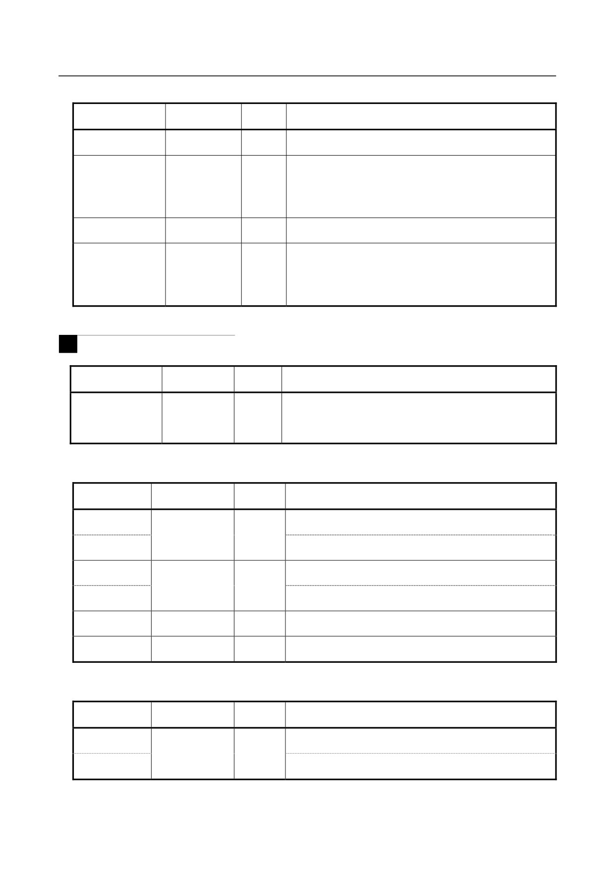
List of system variables and constants
n represents a subscript.
R, W, and R/W are attributes of a variable and indicate read-only, write-only, and read/write enabled,
respectively.
- 162 -
B-64304EN/02
PROGRAMMING
14.CUSTOM MACRO
-
Interface signals
System variable
System variable
Attribute
Description
number
name
#1000-#1031
[#_UI[n]]
R
Interface input signals (BIT), UI000-UI031
NOTE) Subscript n represents a BIT position (0-31).
#1032-#1035
[#_UIL[n]]
R
Interface input signals (LONG), UI000-UI031/ UI100-UI131/
UI200-UI231/UI300-UI331
NOTE) Subscript n (0-3):
0 = UI000-UI031, 1 =
UI100-UI131,
2 = UI200-231, 3 = UI300-UI331
#1100-#1131
[#_UO[n]]
R/W
Interface output signals (BIT), UO000-UO031
NOTE) Subscript n represents a BIT position (0-31).
#1132-#1135
[#_UOL[n]]
R/W
Interface output signals (LONG), UO000-UO031/
UO100-UO131/UO200-UO231/UO300-UO331
NOTE) Subscript n (0-3):
0 = UO000-UO031,
1 = UO100-UO131,
2 = UO200-231, 3 = UO300-UO331
-
Tool compensation value
M
For tool compensation memory A (bit 6 (NGW) of parameter No. 8136 is 1)
System variable
System
Attribute
Description
number
variable name
#2001-#2200
[#_OFS[n]]
R/W
Tool compensation value
Note)Subscript n represents a compensation number (1 to 200).
#10001-#10400
The numbers on the left are also allowed.
Note)Subscript n represents a compensation number (1 to 400).
For tool compensation memory C (bit 6 (NGW) of parameter No. 8136 is 0)
when bit 3 (V10) of parameter No. 6000 is 0
System variable
System variable
Attribute
Description
number
name
#2001-#2200
[#_OFSHW[n]]
R/W
Tool compensation value (H code, wear)
Note)Subscript n represents a compensation number (1 to 200).
#10001-#10400
The numbers on the left are also allowed.
Note)Subscript n represents a compensation number (1 to 400).
#2201-#2400
[#_OFSHG[n]]
R/W
Tool compensation value (H code, geometry)
Note)Subscript n represents a compensation number (1 to 200).
#11001-#11400
The numbers on the left are also allowed.
Note)Subscript n represents a compensation number (1 to 400).
#12001-#12400
[#_OFSDW[n]]
R/W
Tool compensation value (D code, wear)
Note)Subscript n represents a compensation number (1 to 400).
#13001-#13400
[#_OFSDG[n]]
R/W
Tool compensation value (D code, geometry)
Note)Subscript n represents a compensation number (1 to 400).
For tool compensation memory C (bit 6 (NGW) of parameter No. 8136 is 0)
when bit 3 (V10) of parameter No. 6000 is 1
System variable
System variable
Attribute
Description
number
name
#2001-#2200
[#_OFSHG[n]]
R/W
Tool compensation value (H code, geometry)
Note)Subscript n represents a compensation number (1 to 200).
#10001-#10400
The numbers on the left are also allowed.
Note)Subscript n represents a compensation number (1 to 400).
- 163 -
14.CUSTOM MACRO
PROGRAMMING
B-64304EN/02
System variable
System variable
Attribute
Description
number
name
#2201-#2400
[#_OFSHW[n]]
R/W
Tool compensation value (H code, wear)
Note)Subscript n represents a compensation number (1 to 200).
#11001-#11400
The numbers on the left are also allowed.
Note)Subscript n represents a compensation number (1 to 400).
#2401-#2600
[#_OFSDG[n]]
R/W
Tool compensation value (D code, geometry)(Note 1)
Subscript n represents a compensation number (1 to 200).
Note 1) Enabled when bit 5 (D10) of parameter No.6004 = 1.
#12001-#12400
The numbers on the left are also allowed.
Note)Subscript n represents a compensation number (1 to 400).
#2601-#2800
[#_OFSDW[n]]
R/W
Tool compensation value (D code, wear)(Note 1)
Subscript n represents a compensation number (1 to 200).
Note 1) Enabled when bit 5 (D10) of parameter No.6004 = 1.
#13001-#13400
The numbers on the left are also allowed.
Note)Subscript n represents a compensation number (1 to 400).
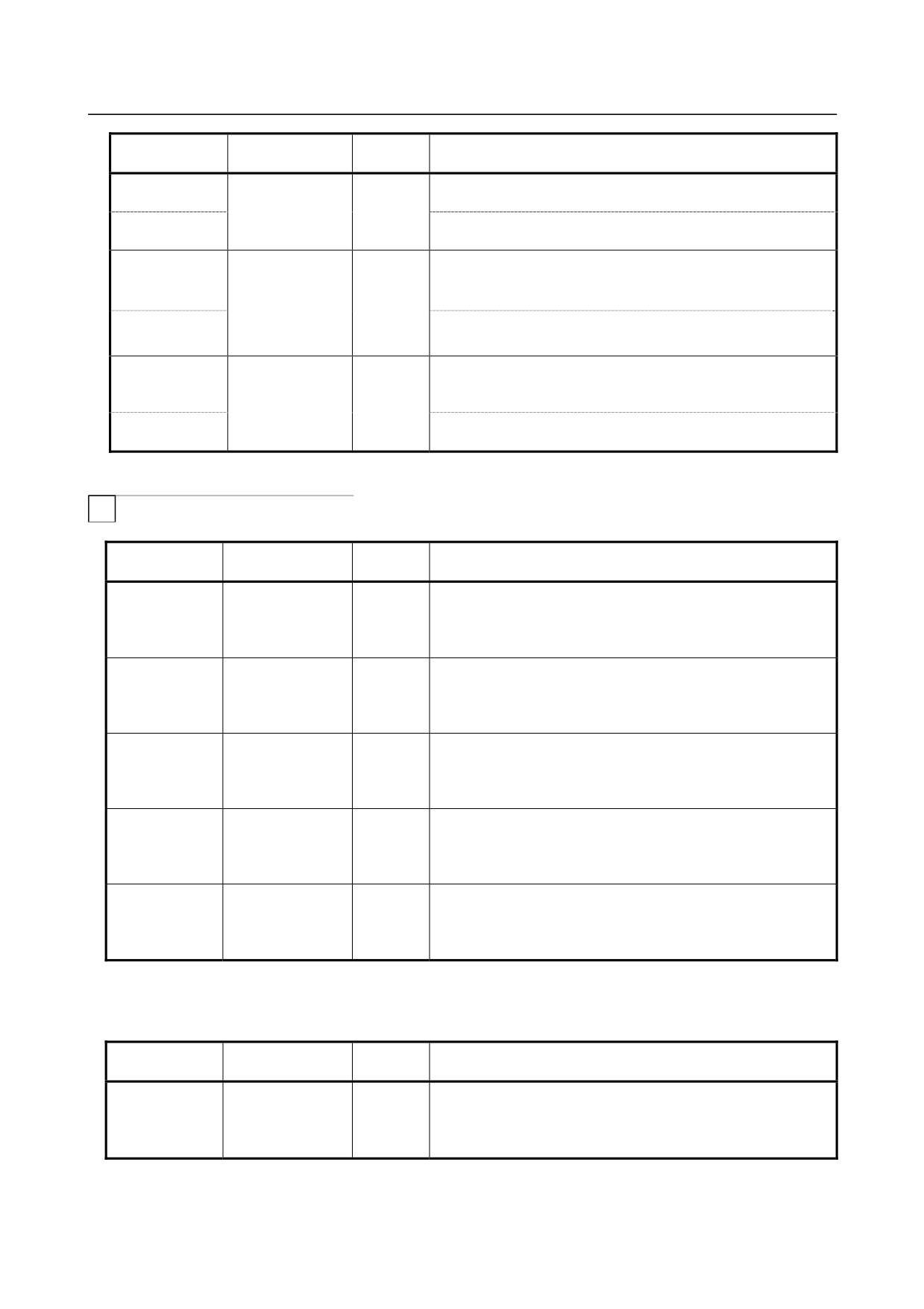
-
Tool compensation value
T
Without tool geometry/wear compensation memory (bit 6 (NGW) of parameter No. 8136 is 1)
System variable
System variable
Attribute
Description
number
name
#2001-#2064
[#_OFSX[n]]
R/W
X-axis compensation value (*1)
Note)Subscript n represents a compensation number (1 to 64).
#10001-#10200
The numbers on the left are also allowed.
Note)Subscript n represents a compensation number (1 to 200).
#2101-#2164
[#_OFSZ[n]]
R/W
Z-axis compensation value (*1)
Note)Subscript n represents a compensation number (1 to 64).
#11001-#11200
The numbers on the left are also allowed.
Note)Subscript n represents a compensation number (1 to 200).
#2201-#2264
[#_OFSR[n]]
R/W
Tool nose radius compensation value
Note)Subscript n represents a compensation number (1 to 64).
#12001-#12200
The numbers on the left are also allowed.
Note)Subscript n represents a compensation number (1 to 200).
#2301-#2364
[#_OFST[n]]
R/W
Virtual tool tip T position
Note)Subscript n represents a compensation number (1 to 64).
#13001-#13200
The numbers on the left are also allowed.
Note)Subscript n represents a compensation number (1 to 200).
#2401-#2449
[#_OFSY[n]]
R/W
Y-axis compensation value (*1)
Note)Subscript n represents a compensation number(1 to 49)
#14001-#14200
The numbers on the left are also allowed.
Note)Subscript n represents a compensation number (1 to 200).
(*1) X-axis: X-axis of basic three axes, Z-axis: Z-axis of basic three axes, Y-axis: Y-axis of basic three
axes
With tool geometry/wear compensation memory (bit 6 (NGW) of parameter No. 8136 is 0)
System variable
System variable
Attribute
Description
number
name
#2001-#2064
[#_OFSXW[n]]
R/W
X-axis compensation value(wear)(※1)
Note)Subscript n represents a compensation number (1 to 64).
#10001-#10200
The numbers on the left are also allowed.
Note)Subscript n represents a compensation number (1 to 200).
- 164 -
B-64304EN/02
PROGRAMMING
14.CUSTOM MACRO
System variable
System variable
Attribute
Description
number
name
#2101-#2164
[#_OFSZW[n]]
R/W
Z-axis compensation value(wear)(※1)
Note)Subscript n represents a compensation number (1 to 64).
#11001-#11200
The numbers on the left are also allowed.
Note)Subscript n represents a compensation number (1 to 200).
#2201-#2264
[#_OFSRW[n]]
R/W
Tool nose radius compensation value(wear)
Note)Subscript n represents a compensation number (1 to 64).
#12001-#12200
The numbers on the left are also allowed.
Note)Subscript n represents a compensation number (1 to 200).
#2301-#2364
[#_OFST[n]]
R/W
Virtual tool tip T position
Note)Subscript n represents a compensation number (1 to 64).
#13001-#13200
The numbers on the left are also allowed.
Note)Subscript n represents a compensation number (1 to 200).
#2401-#2449
[#_OFSYW[n]]
R/W
Y-axis compensation value(wear)(※1)
Note)Subscript n represents a compensation number(1 to 49)
#14001-#14200
The numbers on the left are also allowed.
Note)Subscript n represents a compensation number (1 to 200).
#2451-#2499
[#_OFSYG[n]]
R/W
Y-axis compensation value(geometry)(※1)
Note)Subscript n represents a compensation number(1 to 49)
#19001-#19200
The numbers on the left are also allowed.
Note)Subscript n represents a compensation number (1 to 200).
#2701-#2749
[#_OFSXG[n]]
R/W
X-axis compensation value(geometry)(※1)
Note)Subscript n represents a compensation number(1 to 49)
#15001-#15200
The numbers on the left are also allowed.
Note)Subscript n represents a compensation number (1 to 200).
#2801-#2849
[#_OFSZG[n]]
R/W
Z-axis compensation value(geometry)(※1)
Note)Subscript n represents a compensation number(1 to 49)
#16001-#16200
The numbers on the left are also allowed.
Note)Subscript n represents a compensation number (1 to 200).
#2901-#2964
[#_OFSRG[n]]
R/W
Tool nose radius compensation value(geometry)
Note)Subscript n represents a compensation number (1 to 64).
#17001-#17200
The numbers on the left are also allowed.
Note)Subscript n represents a compensation number (1 to 200).
(*1) X-axis: X-axis of basic three axes, Z-axis: Z-axis of basic three axes, Y-axis: Y-axis of basic three
axes
-
Workpiece coordinate system shift amount
T
System variable
System variable
Attribute
Description
number
name
#2501
[#_WKSFTX]
R/W
X-axis workpiece shift amount
#2601
[#_WKSFTZ]
R/W
Z-axis workpiece shift amount
X-axis: X-axis of basic three axes, Z-axis: Z-axis of basic three axes
-
Automatic operation or the like
System variable
System
Attribute
Description
number
variable name
#3000
[#_ALM]
W
Macro alarm
#3001
[#_CLOCK1]
R/W
Clock 1 (ms)
#3002
[#_CLOCK2]
R/W
Clock 2 (hr)
- 165 -
14.CUSTOM MACRO
PROGRAMMING
B-64304EN/02
System variable
System
Attribute
Description
number
variable name
#3003
[#_CNTL1]
R/W
Enable or disable the suppression of single block stop.
Enable or disable the waiting of the auxiliary function completion
signal.
#3003 bit0
[#_M_SBK]
R/W
Enable or disable the suppression of single block stop.
#3003 bit1
[#_M_FIN]
R/W
Enable or disable waiting for the auxiliary function completion signal.
#3004
[#_CNTL2]
R/W
Enable or disable feed hold.
Enable or disable feedrate override.
Enable or disable exact stop check.
#3004 bit0
[#_M_FHD]
R/W
Enable or disable feed hold.
#3004 bit1
[#_M_OV]
R/W
Enable or disable feedrate override.
#3004 bit2
[#_M_EST]
R/W
Enable or disable exact stop check.
#3005
[#_SETDT]
R/W
Read/write setting data.
#3006
[#_MSGSTP]
W
Stop with a message.
#3007
[#_MRIMG]
R
Status of a mirror image (DI and setting)
#3008
[#_PRSTR]
R
Restarting/not restarting a program
-
Time
System variable
System variable
Attribute
Description
number
name
#3011
[#_DATE]
R
Year/Month/Date
#3012
[#_TIME]
R
Hour/Minute/Second
-
Number of parts
System variable
System variable
Attribute
Description
number
name
#3901
[#_PRTSA]
R/W
Total number of parts
#3902
[#_PRTSN]
R/W
Number of required parts
-
Tool compensation memory
M
System variable
System variable
Attribute
Description
number
name
#3980
[#_OFSMEM]
R
Tool compensation memory information
-
Main program number
System variable
System variable
Attribute
Description
number
name
#4000
[#_MAINO]
R
Main program number
-
Modal information
M
System variable
System variable
Attribute
Description
number
name
#4001-#4030
[#_BUFG[n]]
R
Modal information on blocks that have been specified by last
minute (G code)
Note)Subscript n represents a G code group number.
#4102
[#_BUFB]
R
Modal information on blocks that have been specified by last
minute (B code)
- 166 -
B-64304EN/02
PROGRAMMING
14.CUSTOM MACRO
System variable
System variable
Attribute
Description
number
name
#4107
[#_BUFD]
R
Modal information on blocks that have been specified by last
minute (D code)
#4108
[#_BUFE]
R
Modal information on blocks that have been specified by last
minute (E code)
#4109
[#_BUFF]
R
Modal information on blocks that have been specified by last
minute (F code)
#4111
[#_BUFH]
R
Modal information on blocks that have been specified by last
minute (H code)
#4113
[#_BUFM]
R
Modal information on blocks that have been specified by last
minute (M code)
#4114
[#_BUFN]
R
Modal information on blocks that have been specified by last
minute (sequence number)
#4115
[#_BUFO]
R
Modal information on blocks that have been specified by last
minute (program number)
#4119
[#_BUFS]
R
Modal information on blocks that have been specified by last
minute (S code)
#4120
[#_BUFT]
R
Modal information on blocks that have been specified by last
minute (T code)
#4130
[#_BUFWZP]
R
Modal information on blocks that have been specified by last
minute (additional workpiece coordinate system number)
#4201-#4230
[#_ACTG[n]]
R
Modal information on the block currently being executed (G code)
Note)Subscript n represents a G code group number.
#4302
[#_ACTB]
R
Modal information on the block currently being executed (B code)
#4307
[#_ACTD]
R
Modal information on the block currently being executed (D code)
#4308
[#_ACTE]
R
Modal information on the block currently being executed (E code)
#4309
[#_ACTF]
R
Modal information on the block currently being executed (F code)
#4311
[#_ACTH]
R
Modal information on the block currently being executed (H code)
#4313
[#_ACTM]
R
Modal information on the block currently being executed (M code)
#4314
[#_ACTN]
R
Modal information on the block currently being executed
(sequence number)
#4315
[#_ACTO]
R
Modal information on the block currently being executed
(program number)
#4319
[#_ACTS]
R
Modal information on the block currently being executed (S code)
#4320
[#_ACTT]
R
Modal information on the block currently being executed (T code)
#4330
[#_ACTWZP]
R
Modal information on the block currently being executed
(additional workpiece coordinate system number)
#4401-#4430
[#_INTG[n]]
R
Modal information on interrupted blocks (G code)
Note)Subscript n represents a G code group number.
#4502
[#_INTB]
R
Modal information on interrupted blocks (B code)
#4507
[#_INTD]
R
Modal information on interrupted blocks (D code)
#4508
[#_INTE]
R
Modal information on interrupted blocks (E code)
#4509
[#_INTF]
R
Modal information on interrupted blocks (F code)
#4511
[#_INTH]
R
Modal information on interrupted blocks (H code)
#4513
[#_INTM]
R
Modal information on interrupted blocks (M code)
#4514
[#_INTN]
R
Modal information on interrupted blocks
(sequence number)
#4515
[#_INTO]
R
Modal information on interrupted blocks
(program number)
#4519
[#_INTS]
R
Modal information on interrupted blocks (S code)
#4520
[#_INTT]
R
Modal information on interrupted blocks (T code)
#4530
[#_INTWZP]
R
Modal information on interrupted blocks
(additional workpiece coordinate system number)
- 167 -
14.CUSTOM MACRO
PROGRAMMING
B-64304EN/02
T
System variable
System variable
Attribute
Description
number
name
#4001-#4030
[#_BUFG[n]]
R
Modal information on blocks that have been specified by last
minute (G code)
Note)Subscript n represents a G code group number.
#4108
[#_BUFE]
R
Modal information on blocks that have been specified by last
minute (E code)
#4109
[#_BUFF]
R
Modal information on blocks that have been specified by last
minute
(F code)
#4113
[#_BUFM]
R
Modal information on blocks that have been specified by last
minute (M code)
#4114
[#_BUFN]
R
Modal information on blocks that have been specified by last
minute (sequence number)
#4115
[#_BUFO]
R
Modal information on blocks that have been specified by last
minute (program number)
#4119
[#_BUFS]
R
Modal information on blocks that have been specified by last
minute (S code)
#4120
[#_BUFT]
R
Modal information on blocks that have been specified by last
minute (T code)
#4201-#4230
[#_ACTG[n]]
R
Modal information on the block currently being executed (G code)
Note)Subscript n represents a G code group number.
#4308
[#_ACTE]
R
Modal information on the block currently being executed (E code)
#4309
[#_ACTF]
R
Modal information on the block currently being executed (F code)
#4313
[#_ACTM]
R
Modal information on the block currently being executed (M code)
#4314
[#_ACTN]
R
Modal information on the block currently being executed
(sequence number)
#4315
[#_ACTO]
R
Modal information on the block currently being executed
(program number)
#4319
[#_ACTS]
R
Modal information on the block currently being executed (S code)
#4320
[#_ACTT]
R
Modal information on the block currently being executed (T code)
#4401-#4430
[#_INTG[n]]
R
Modal information on interrupted blocks (G code)
Note)Subscript n represents a G code group number.
#4508
[#_INTE]
R
Modal information on interrupted blocks (E code)
#4509
[#_INTF]
R
Modal information on interrupted blocks (F code)
#4513
[#_INTM]
R
Modal information on interrupted blocks (M code)
#4514
[#_INTN]
R
Modal information on interrupted blocks
(sequence number)
#4515
[#_INTO]
R
Modal information on interrupted blocks
(program number)
#4519
[#_INTS]
R
Modal information on interrupted blocks (S code)
#4520
[#_INTT]
R
Modal information on interrupted blocks (T code)
-
Position information
System variable
System variable
Attribute
Description
number
name
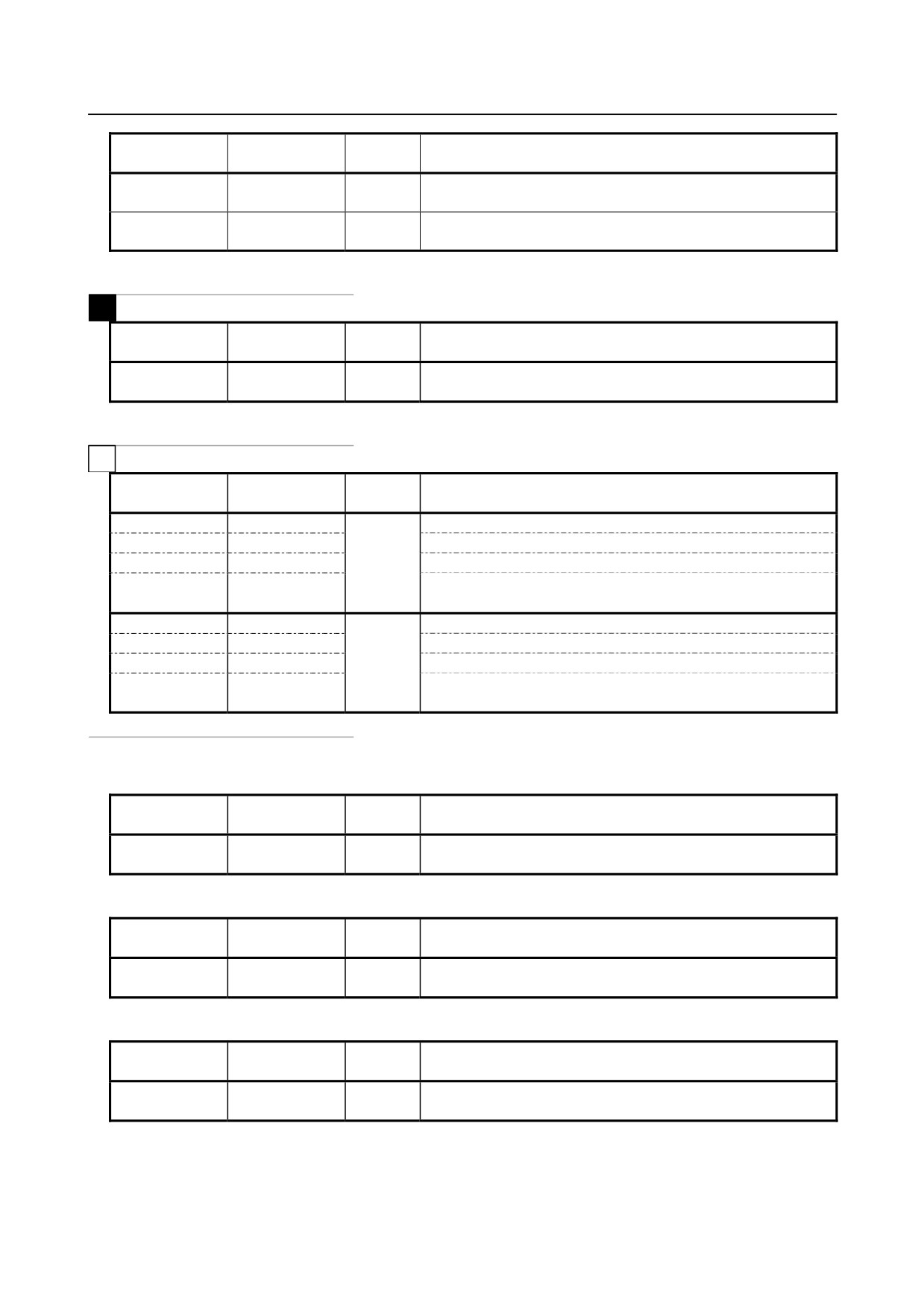
#5001-#5005
[#_ABSIO[n]]
R
End point position of the previous block (workpiece coordinate
system)
Note) Subscript n represents an axis number (1 to 5)
#5021-#5025
[#_ABSMT[n]]
R
Specified current position (machine coordinate system)
Note) Subscript n represents an axis number (1 to 5).
- 168 -
B-64304EN/02
PROGRAMMING
14.CUSTOM MACRO
System variable
System variable
Attribute
Description
number
name
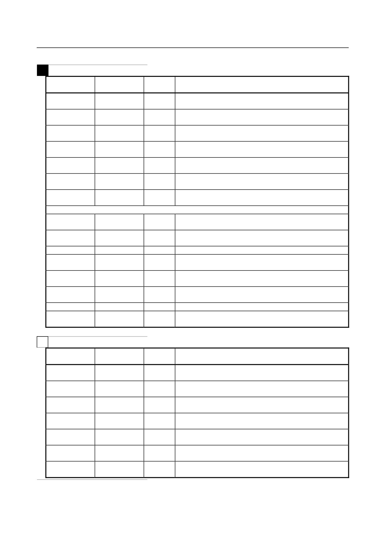
#5041-#5045
[#_ABSOT[n]]
R
Specified current position (workpiece coordinate system)
Note) Subscript n represents an axis number (1 to 5).
#5061-#5065
[#_ABSKP[n]]
R
Skip position (workpiece coordinate system)
Note) Subscript n represents an axis number (1 to 5).
-
Tool length compensation value
M
System variable
System variable
Attribute
Description
number
name
#5081-#5085
[#_TOFS[n]]
R
Tool length compensation value
Note) Subscript n represents an axis number (1 to 5).
-
Tool offset value
T
System variable
System variable
Attribute
Description
number
name
#5081
[#_TOFSWX]
R
X-axis tool offset (wear)
#5082
[#_TOFSWZ]
Z-axis tool offset (wear)
#5083
[#_TOFSWY]
Y-axis tool offset (wear)
#5084
[#_TOFS[n]]
Tool offset (wear) for an arbitrary axis
#5085
Note) Subscript n represents an axis number (4 or 5).
#5121
[#_TOFSGX]
R
X-axis tool offset (geometry)
#5122
[#_TOFSGZ]
Y-axis tool offset (geometry)
#5123
[#_TOFSGY]
Z-axis tool offset (geometry)
#5124
[#_TOFSG[n]]
Tool offset (geometry) for an arbitrary axis
#5125
Note) Subscript n represents an axis number (4 or 5).
X-axis: X-axis of basic three axes, Z-axis: Z-axis of basic three axes, Y-axis: Y-axis of basic three axes
-
Servo position deviation
System variable
System variable
Attribute
Description
number
name
#5101-#5105
[#_SVERR[n]]
R
Servo positional deviation
Note) Subscript n represents an axis number (1 to 5).
-
Manual handle interruption
System variable
System variable
Attribute
Description
number
name
#5121-#5125
[#_MIRTP[n]]
R
Manual handle interruption
Note) Subscript n represents an axis number (1 to 5).
-
Distance to go
System variable
System variable
Attribute
Description
number
name
#5181-#5185
[#_DIST[n]]
R
Distance to go
Note) Subscript n represents an axis number (1 to 5).
- 169 -
14.CUSTOM MACRO
PROGRAMMING
B-64304EN/02
-
Workpiece origin offset value, extended workpiece origin offset value
M
System variable
System variable
Attribute
Description
number
name
#5201-#5205
[#_WZCMN[n]]
R/W
External workpiece origin offset value
Note)Subscript n represents an axis number (1 to 5).
#5221-#5225
[#_WZG54[n]]
R/W
G54 workpiece origin offset value
Note)Subscript n represents an axis number (1 to 5).
#5241-#5245
[#_WZG55[n]]
R/W
G55 workpiece origin offset value
Note)Subscript n represents an axis number (1 to 5).
#5261-#5265
[#_WZG56[n]]
R/W
G56 workpiece origin offset value
Note)Subscript n represents an axis number (1 to 5).
#5281-#5285
[#_WZG57[n]]
R/W
G57 workpiece origin offset value
Note)Subscript n represents an axis number (1 to 5).
#5301-#5305
[#_WZG58[n]]
R/W
G58 workpiece origin offset value
Note)Subscript n represents an axis number (1 to 5).
#5321-#5325
[#_WZG59[n]]
R/W
G59 workpiece origin offset value
Note)Subscript n represents an axis number (1 to 5).
Listed below are extended workpiece origin offset values.
#7001-#7005
[#_WZP1[n]]
R/W
G54.1P1 workpiece origin offset value
Note)Subscript n represents an axis number (1 to 5).
#7021-#7025
[#_WZP2[n]]
R/W
G54.1P2 workpiece origin offset value
Note)Subscript n represents an axis number (1 to 5).
:
:
:
:
#7941-#7945
[#_WZP48[n]]
R/W
G54.1P48 workpiece origin offset value
Note)Subscript n represents an axis number (1 to 5).
#14001-#14005
[#_WZP1[n]]
R/W
G54.1P1 workpiece origin offset value
Note)Subscript n represents an axis number (1 to 5).
#14021-#14025
[#_WZP2[n]]
R/W
G54.1P2 workpiece origin offset value
Note)Subscript n represents an axis number (1 to 5).
:
:
:
:
#14941-#14945
[#_WZP48[n]]
R/W
G54.1P48 workpiece origin offset value
Note)Subscript n represents an axis number (1 to 5).
T
System variable
System variable
Attribute
Description
number
name
#5201-#5205
[#_WZCMN[n]]
R/W
External workpiece origin offset value
Note)Subscript n represents an axis number (1 to 5).
#5221-#5225
[#_WZG54[n]]
R/W
G54 workpiece origin offset value
Note)Subscript n represents an axis number (1 to 5).
#5241-#5245
[#_WZG55[n]]
R/W
G55 workpiece origin offset value
Note)Subscript n represents an axis number (1 to 5).
#5261-#5265
[#_WZG56[n]]
R/W
G56 workpiece origin offset value
Note)Subscript n represents an axis number (1 to 5).
#5281-#5285
[#_WZG57[n]]
R/W
G57 workpiece origin offset value
Note)Subscript n represents an axis number (1 to 5).
#5301-#5305
[#_WZG58[n]]
R/W
G58 workpiece origin offset value
Note)Subscript n represents an axis number (1 to 5).
#5321-#5325
[#_WZG59[n]]
R/W
G59 workpiece origin offset value
Note)Subscript n represents an axis number (1 to 5).
- 170 -
B-64304EN/02
PROGRAMMING
14.CUSTOM MACRO
-
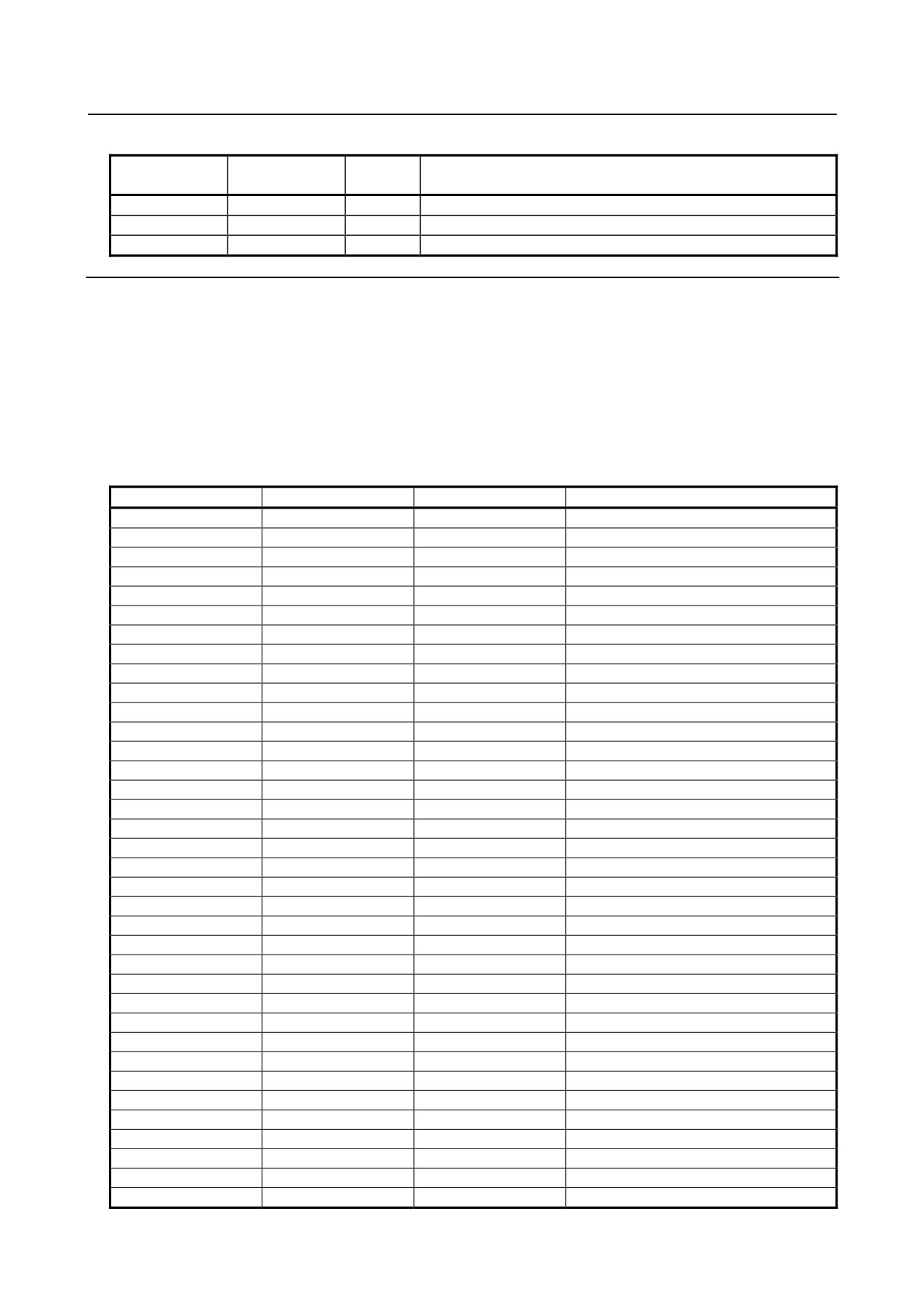
System constant
System constant
System constant
Attribute
Description
number
name
#0,#3100
[#_EMPTY]
R
Null
#3101
[#_PI]
R
Circular constant π = 3.14159265358979323846
#3102
[#_E]
R
Base of natural logarithm e = 2.71828182845904523536
Explanation
R, W, and R/W are attributes of a variable and represents read-only, write-only, and read/write enabled,
respectively.
-
Interface signal #1000-#1031, #1032, #1033-#1035 (Attribute: R)
#1100-#1115, #1132, #1133-#1135 (Attribute: R/W)
[Input signal]
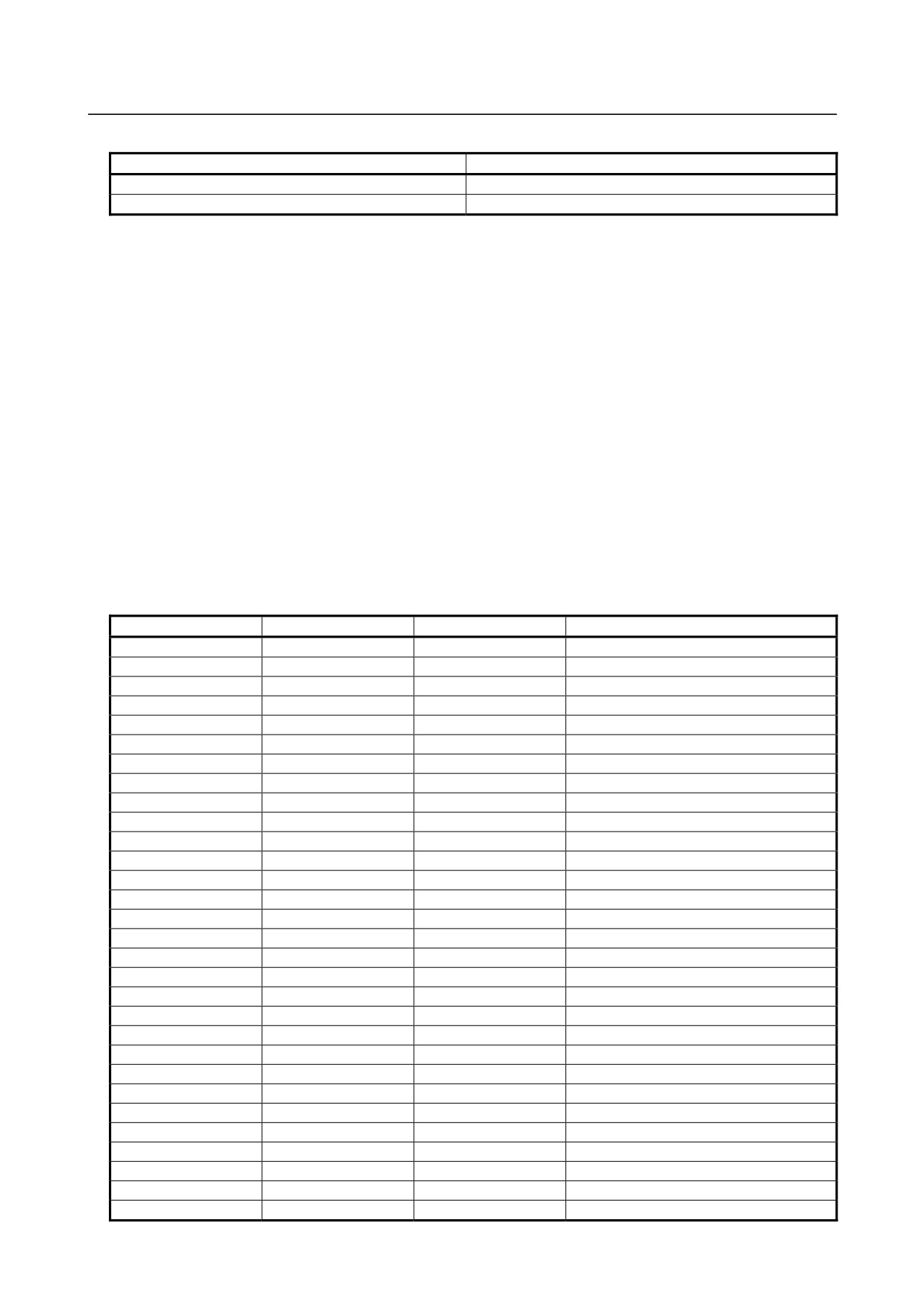
The status of interface input signals can be obtained by reading the value of system variables #1000 to
#1032.
Variable number
Variable name
Point
Interface input signal
#1000
[#_UI[0]]
1
UI000
(20)
#1001
[#_UI[1]]
1
UI001
(21)
#1002
[#_UI[2]]
1
UI002
(22)
#1003
[#_UI[3]]
1
UI003
(23)
#1004
[#_UI[4]]
1
UI004
(24)
#1005
[#_UI[5]]
1
UI005
(25)
#1006
[#_UI[6]]
1
UI006
(26)
#1007
[#_UI[7]]
1
UI007
(27)
#1008
[#_UI[8]]
1
UI008
(28)
#1009
[#_UI[9]]
1
UI009
(29)
#1010
[#_UI[10]]
1
UI010
(210)
#1011
[#_UI[11]]
1
UI011
(211)
#1012
[#_UI[12]]
1
UI012
(212)
#1013
[#_UI[13]]
1
UI013
(213)
#1014
[#_UI[14]]
1
UI014
(214)
#1015
[#_UI[15]]
1
UI015
(215)
#1016
[#_UI[16]]
1
UI016
(216)
#1017
[#_UI[17]]
1
UI017
(217)
#1018
[#_UI[18]]
1
UI018
(218)
#1019
[#_UI[19]]
1
UI019
(219)
#1020
[#_UI[20]]
1
UI020
(220)
#1021
[#_UI[21]]
1
UI021
(221)
#1022
[#_UI[22]]
1
UI022
(222)
#1023
[#_UI[23]]
1
UI023
(223)
#1024
[#_UI[24]]
1
UI024
(224)
#1025
[#_UI[25]]
1
UI025
(225)
#1026
[#_UI[26]]
1
UI026
(226)
#1027
[#_UI[27]]
1
UI027
(227)
#1028
[#_UI[28]]
1
UI028
(228)
#1029
[#_UI[29]]
1
UI029
(229)
#1030
[#_UI[30]]
1
UI030
(230)
#1031
[#_UI[31]]
1
UI031
(231)
#1032
[#_UIL[0]]
32
UI000-UI031
#1033
[#_UIL[1]]
32
UI100-UI131
#1034
[#_UIL[2]]
32
UI200-UI231
#1035
[#_UIL[3]]
32
UI300-UI331
- 171 -
14.CUSTOM MACRO
PROGRAMMING
B-64304EN/02
Variable value
Input signal
1.0
Contact closed
0.0
Contact opened
Since the read value is 1.0 or 0.0 regardless of the unit system, the unit system must be considered when a
macro is created.
The input signals at 32 points can be read at a time by reading from system variables #1032 to #1035.
30
31
#1032 =
#[1000 +i] × 2i−#
1031
×
2
∑
i
=0
30
i
31
#[1032+n]=
{
2
×V
}
−2
×V
∑
i
31
i
=0
When UIni = 0, Vi = 0.
When
UIni = 1, Vi = 1.
n = 0-3
[Output signal]
Interface output signals can be sent by assigning values to system variables #1100 to #1132 for sending
interface signals.
Variable number
Variable name
Point
Interface input signal
#1100
[#_UO[0]]
1
UO000
(20)
#1101
[#_UO[1]]
1
UO001
(21)
#1102
[#_UO[2]]
1
UO002
(22)
#1103
[#_UO[3]]
1
UO003
(23)
#1104
[#_UO[4]]
1
UO004
(24)
#1105
[#_UO[5]]
1
UO005
(25)
#1106
[#_UO[6]]
1
UO006
(26)
#1107
[#_UO[7]]
1
UO007
(27)
#1108
[#_UO[8]]
1
UO008
(28)
#1109
[#_UO[9]]
1
UO009
(29)
#1110
[#_UO[10]]
1
UO010
(210)
#1111
[#_UO[11]]
1
UO011
(211)
#1112
[#_UO[12]]
1
UO012
(212)
#1113
[#_UO[13]]
1
UO013
(213)
#1114
[#_UO[14]]
1
UO014
(214)
#1115
[#_UO[15]]
1
UO015
(215)
#1116
[#_UO[16]]
1
UO016
(216)
#1117
[#_UO[17]]
1
UO017
(217)
#1118
[#_UO[18]]
1
UO018
(218)
#1119
[#_UO[19]]
1
UO019
(219)
#1120
[#_UO[20]]
1
UO020
(220)
#1121
[#_UO[21]]
1
UO021
(221)
#1122
[#_UO[22]]
1
UO022
(222)
#1123
[#_UO[23]]
1
UO023
(223)
#1124
[#_UO[24]]
1
UO024
(224)
#1125
[#_UO[25]]
1
UO025
(225)
#1126
[#_UO[26]]
1
UO026
(226)
#1127
[#_UO[27]]
1
UO027
(227)
#1128
[#_UO[28]]
1
UO028
(228)
#1129
[#_UO[29]]
1
UO029
(229)
- 172 -
B-64304EN/02
PROGRAMMING
14.CUSTOM MACRO
Variable number
Variable name
Point
Interface input signal
#1130
[#_UO[30]]
1
UO030
(230)
#1131
[#_UO[31]]
1
UO031
(231)
#1132
[#_UOL[0]]
32
UO000-UO031
#1133
[#_UOL[1]]
32
UO100-UO131
#1134
[#_UOL[2]]
32
UO200-UO231
#1135
[#_UOL[3]]
32
UO300-UO331
Variable value
Input signal
1.0
Contact closed
0.0
Contact opened
The output signals at 32 points can be written at a time by writing to system variables #1132 to #1135.
The signals can also be read.
30
31
#1132 =
#[1100 +i] × 2i−#
1131
×
2
∑
i
=0
30
i
31
#[1132+n]=
{
2
×V
}
−2
×V
∑
i
31
i=0
When UIni = 0, Vi = 0.
When
UIni = 1, Vi = 1.
n = 0-3
NOTE
1 When a value other than 1.0 or 0.0 is assigned to variables #1100 to #1131, it is
assumed as follows.
<null> is assumed to be 0.
A value other than <null> or 0 is assumed to be 1.
Where, a value less than 0.00000001 is undefined.
2 When any of UI016 to UI031, UI100 to UI131, UI200 to UI231, UI300 to UI331,
UO016 to UO031, UO200 to UO231, and UO300 to UO331 are used, parameter
MIF (No.6001#0) must be set to 1.
Example
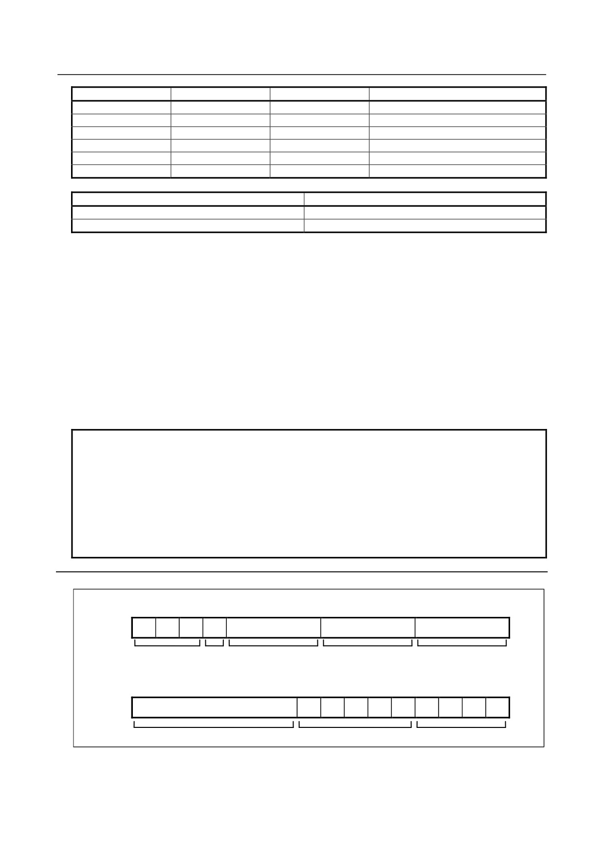
Structure of DI
215
214
213
212
211
210
29
28
27
26
25
24
23
22
21
20
Used for other
101
Sign
102
100
purposes
Structure of DO
28
27
26
25
24
23
22
21
20
Not used
Used for other purposes
Address
- 173 -
14.CUSTOM MACRO
PROGRAMMING
B-64304EN/02
<1> Address switching signed BCD 3 digits are read.
Macro calling instruction
G65 P9100 D (address);
A custom macro body is created as follows.
O9100 ;
#1132 = #1132 AND 496 OR #7 ; : Address sending
G65 P9101 T60 ;
:
Timer macro
#100 = BIN[#1032 AND 4095] ;
:
BCD 3 digits are read.
IF [#1012 EQ
0] GOTO
9100 ;
:
A sign is attached.
#100 = -#100
N9100 M99 ;
<2> Eight types of address switching signed BCD 6 digits (3-digit integer part + 3-digit fractional part)
are read into #101.
Structure on the machine side
When DO 20 = 0:
Data with 3 decimal places
When DO 20 = 1:
Data with 3-digit integer part
When DO 23 to 21 = 000:
No1 data when #1 = 0
When DO 23 to 21 = 001:
No2 data when #2 = 0
:
When DO 23 to 21 = 111: No8 data when #8 = 0
Macro calling instruction
G65 P9101 D (data number);
A custom macro body is created as follows.
O9101 ;
G65 P9101 D[#1*2+1] ;
#101 = #100
;
G65 P9100 D[#1*2] ;
#101 = #101 + #100 / 1000 ;
M99 ;
-
Tool compensation value #2001-#2800, #10001-#13400 (Attribute: R/W)
M
The compensation values can be obtained by reading system variables #2001 to #2800 or #10001 to
#13400 for tool compensation. The compensation values can also be changed by assigning values to the
system variables.
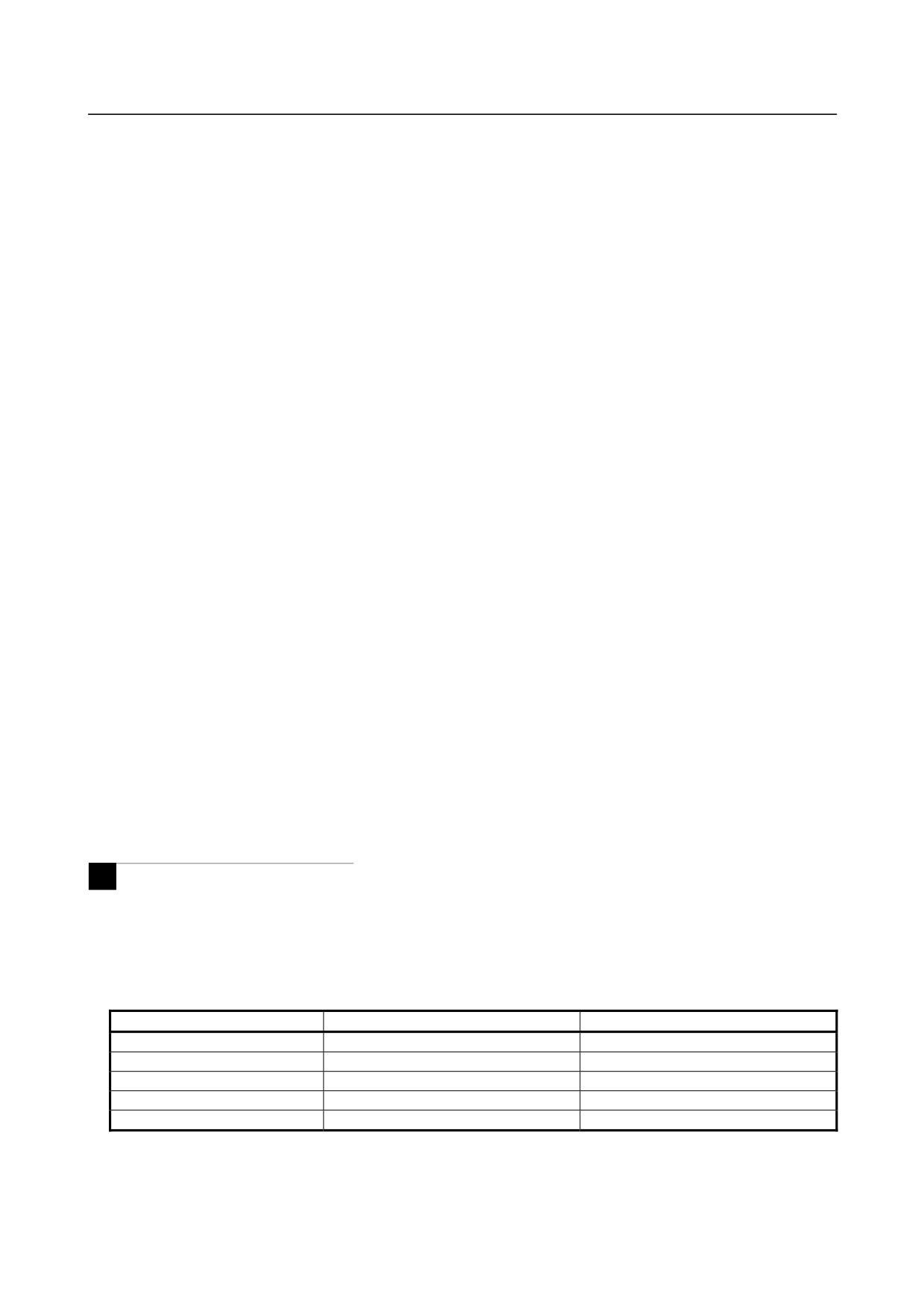
<1> Tool compensation memory A (bit 6 (NGW) of parameter No.8136 = 1)
•
When the number of compensations is 200 or less
Compensation number
Variable number
Variable name
1
#2001
[#_OFS[1]]
2
#2002
[#_OFS[2]]
:
:
:
199
#2199
[#_OFS[199]]
200
#2200
[#_OFS[200]]
- 174 -
B-64304EN/02
PROGRAMMING
14.CUSTOM MACRO
•
When the number of compensations is 400 (For compensation with a compensation number of
200 or less, #2001 to #2200 can also be used.)
Compensation number
Variable number
Variable name
1
#10001
[#_OFS[1]]
2
#10002
[#_OFS[2]]
:
:
:
399
#10399
[#_OFS[399]]
400
#10400
[#_OFS[400]]
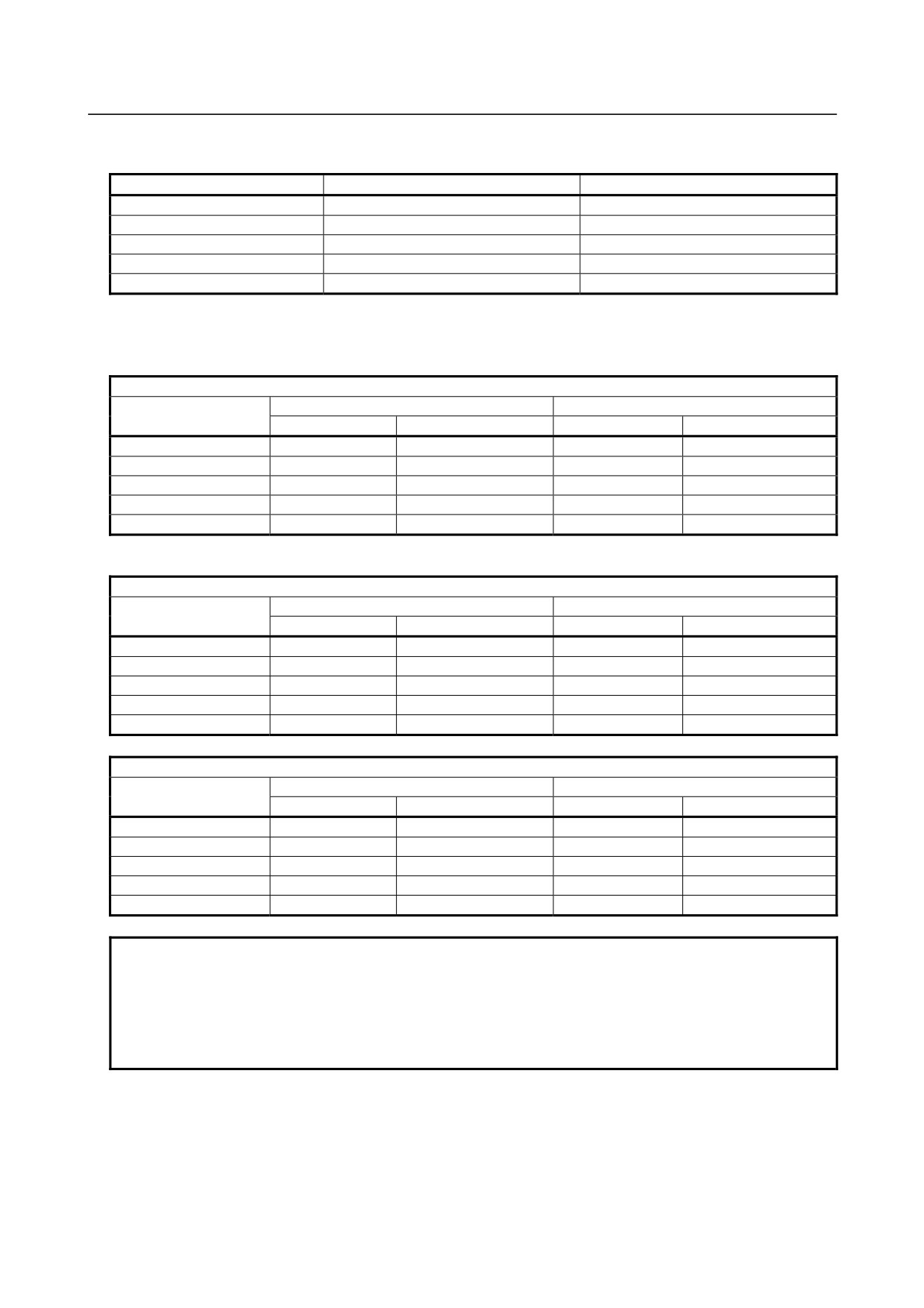
<2> Tool compensation memory C (bit 6 (NGW) of parameter No.8136 = 0)
•
When the number of compensations is 200 or less
When bit 3 (V10) of parameter No.6000 = 0
H code
Geometry
Wear
Compensation number
Variable number
Variable name
Variable number
Variable name
1
#2201
[#_OFSHG[1]]
#2001
[#_OFSHW[1]]
2
#2202
[#_OFSHG[2]]
#2002
[#_OFSHW[2]]
:
:
:
:
:
199
#2399
[#_OFSHG[199]]
#2199
[#_OFSHW[199]]
200
#2400
[#_OFSHG[200]]
#2200
[#_OFSHW[200]]
When bit 3 (V10) of parameter No.6000 = 1
H code
Geometry
Wear
Compensation number
Variable number
Variable name
Variable number
Variable name
1
#2001
[#_OFSHG[1]]
#2201
[#_OFSHW[1]]
2
#2002
[#_OFSHG[2]]
#2202
[#_OFSHW[2]]
:
:
:
:
:
199
#2199
[#_OFSHG[199]]
#2399
[#_OFSHW[199]]
200
#2200
[#_OFSHG[200]]
#2400
[#_OFSHW[200]]
D code
Geometry
Wear
Compensation number
Variable number
Variable name
Variable number
Variable name
1
#2401
[#_OFSDG[1]]
#2601
[#_OFSDW[1]]
2
#2402
[#_OFSDG[2]]
#2602
[#_OFSDW[2]]
:
:
:
:
:
199
#2599
[#_OFSDG[199]]
#2799
[#_OFSDW[199]]
200
#2600
[#_OFSDG[200]]
#2800
[#_OFSDW[200]]
NOTE
1 When #2401 to #2800 are used for reading or writing of D codes, bit 5 (D10) of
parameter No.6004 must be set to 1.
2 When bit 5 (D10) of parameter No.6004 is set to 1, system variables #2500 to
#2806 for workpiece origin offset cannot be used. Use system variables #5201
to #5324.
•
When the number of compensations is 400 (For compensation with a compensation number of
200 or less, #2001 to #2800 can also be used.)
- 175 -
14.CUSTOM MACRO
PROGRAMMING
B-64304EN/02
When bit 3 (V10) of parameter No.6000 = 0
H code
Geometry
Wear
Compensation number
Variable number
Variable name
Variable number
Variable name
1
#11001
[#_OFSHG[1]]
#10001
[#_OFSHW[1]]
2
#11002
[#_OFSHG[2]]
#10002
[#_OFSHW[2]]
:
:
:
:
:
399
#11399
[#_OFSHG[399]]
#10399
[#_OFSHW[399]]
400
#11400
[#_OFSHG[400]]
#10400
[#_OFSHW[400]]
D code
Geometry
Wear
Compensation number
Variable number
Variable name
Variable number
Variable name
1
#13001
[#_OFSDG[1]]
#12001
[#_OFSDW[1]]
2
#13002
[#_OFSDG[2]]
#12002
[#_OFSDW[2]]
:
:
:
:
:
399
#13399
[#_OFSDG[399]]
#12399
[#_OFSDW[399]]
400
#13400
[#_OFSDG[400]]
#12400
[#_OFSDW[400]]
When bit 3 (V10) of parameter No.6000 = 1
H code
Geometry
Wear
Compensation number
Variable number
Variable name
Variable number
Variable name
1
#10001
[#_OFSHG[1]]
#11001
[#_OFSHW[1]]
2
#10002
[#_OFSHG[2]]
#11002
[#_OFSHW[2]]
:
:
:
:
:
399
#10399
[#_OFSHG[399]]
#11399
[#_OFSHW[399]]
400
#10400
[#_OFSHG[400]]
#11400
[#_OFSHW[400]]
D code
Geometry
Wear
Compensation number
Variable number
Variable name
Variable number
Variable name
1
#12001
[#_OFSDG[1]]
#13001
[#_OFSDW[1]]
2
#12002
[#_OFSDG[2]]
#13002
[#_OFSDW[2]]
:
:
:
:
399
#12399
[#_OFSDG[399]]
#13399
[#_OFSDW[399]]
400
#12400
[#_OFSDG[400]]
#13400
[#_OFSDW[400]]
-
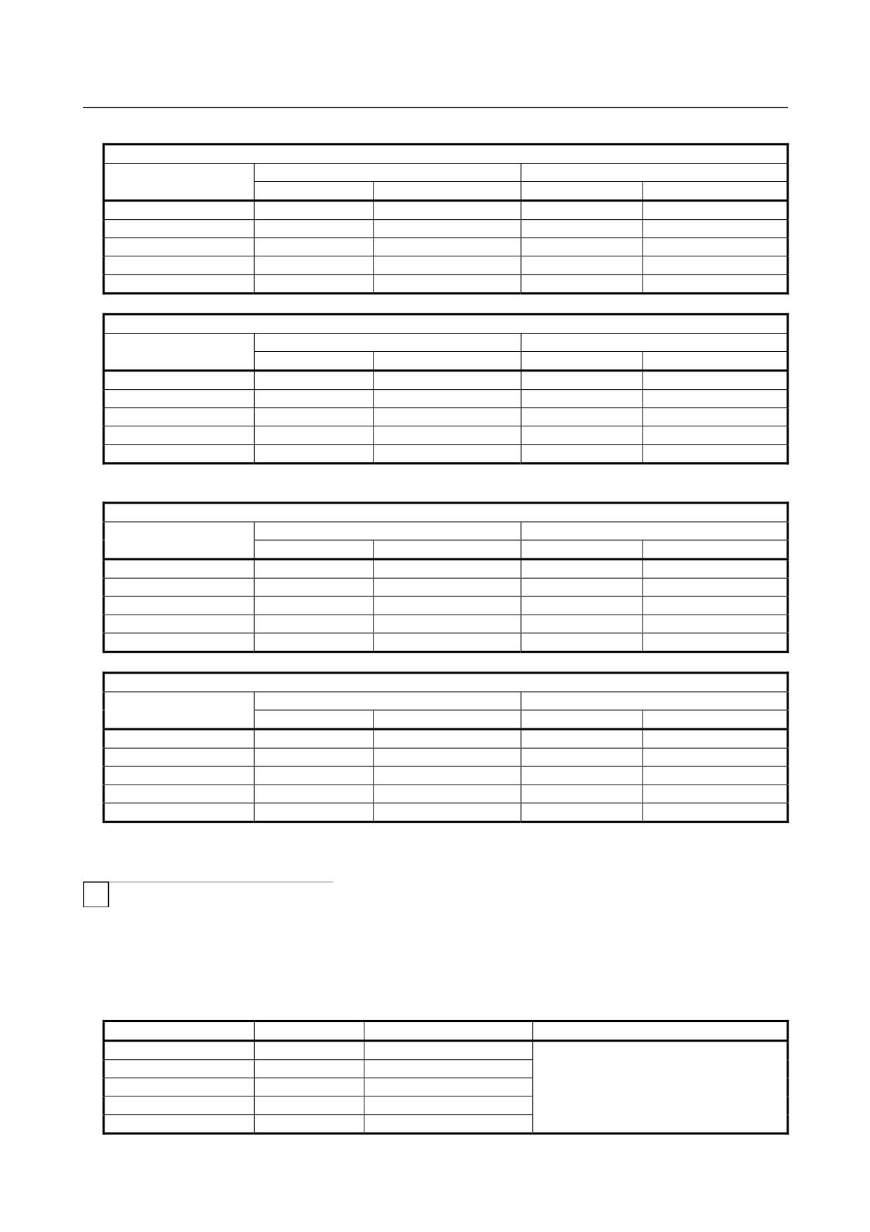
Tool compensation value #2001-#2964, #10001-#19200 (Attribute: R/W)
T
The compensation values can be obtained by reading system variables #2001 to #2964 or #10001 to
#19200 for tool compensation. The compensation values can also be changed by assigning values to the
system variables.
<1> Without tool geometry/wear compensation memory (bit 6 (NGW) of parameter No.8136 = 1)
•
When the number of compensations is 64 or less
Compensation number
Variable number
Variable name
Description
1
#2001
[#_OFSX[1]]
2
#2002
[#_OFSX[2]]
:
:
:
X-axis compensation value (*1)
63
#2063
[#_OFSX[63]]
64
#2064
[#_OFSX[64]]
- 176 -
B-64304EN/02
PROGRAMMING
14.CUSTOM MACRO
Compensation number
Variable number
Variable name
Description
1
#2101
[#_OFSZ[1]]
2
#2102
[#_OFSZ[2]]
:
:
:
Z-axis compensation value (*1)
63
#2163
[#_OFSZ[63]]
64
#2164
[#_OFSZ[64]]
1
#2201
[#_OFSR[1]]
2
#2202
[#_OFSR[2]]
:
:
:
Tool nose radius compensation value
63
#2263
[#_OFSR[63]]
64
#2264
[#_OFSR[64]]
1
#2301
[#_OFST[1]]
2
#2302
[#_OFST[2]]
:
:
:
Virtual tool tipT position
63
#2363
[#_OFST[63]]
64
#2364
[#_OFST[64]]
1
#2401
[#_OFSY[1]]
2
#2402
[#_OFSY[2]]
:
:
:
Y-axis compensation value (*1)
48
#2448
[#_OFSY[48]]
49
#2449
[#_OFSY[49]]
(*1) X-axis: X-axis of basic three axes, Z-axis: Z-axis of basic three axes, Y-axis: Y-axis of basic three
axes
•
When the number of compensations is 200
(For compensation with a compensation number
of 64 or less, #2001 to #2449 can also be used.)
Compensation number
Variable number
Variable name
Description
1
#10001
[#_OFSX[1]]
2
#10002
[#_OFSX[2]]
:
:
:
X-axis compensation value (*1)
199
#10199
[#_OFSX[199]]
200
#10200
[#_OFSX[200]]
1
#11001
[#_OFSZ[1]]
2
#11002
[#_OFSZ[2]]
:
:
:
Z-axis compensation value (*1)
199
#11199
[#_OFSZ[199]]
200
#11200
[#_OFSZ[200]]
1
#12001
[#_OFSR[1]]
2
#12002
[#_OFSR[2]]
:
:
:
Tool nose radius compensation value
199
#12199
[#_OFSR[199]]
200
#12200
[#_OFSR[200]]
1
#13001
[#_OFST[1]]
2
#13002
[#_OFST[2]]
:
:
:
Virtual tool tip T position
199
#13199
[#_OFST[199]]
200
#13200
[#_OFST[200]]
1
#14001
[#_OFSY[1]]
2
#14002
[#_OFSY[2]]
:
:
:
Y-axis compensation value (*1)
199
#14199
[#_OFSY[199]]
200
#14200
[#_OFSY[200]]
(*1) X-axis: X-axis of basic three axes, Z-axis: Z-axis of basic three axes, Y-axis: Y-axis of basic three
axes
- 177 -
14.CUSTOM MACRO
PROGRAMMING
B-64304EN/02
<2> With tool geometry/wear compensation memory (bit 6 (NGW) of parameter No.8136 = 0)
•
When the number of compensations is 64 or less
Compensation number
Variable number
Variable name
Description
1
#2001
[#_OFSXW[1]]
2
#2002
[#_OFSXW[2]]
:
:
:
X-axis compensation value (wear) (*1)
63
#2063
[#_OFSXW[63]]
64
#2064
[#_OFSXW[64]]
1
#2101
[#_OFSZW[1]]
2
#2102
[#_OFSZW[2]]
:
:
:
Z-axis compensation value (wear) (*1)
63
#2163
[#_OFSZW[63]]
64
#2164
[#_OFSZW[64]]
1
#2201
[#_OFSRW[1]]
2
#2202
[#_OFSRW [2]]
Tool nose radius compensation value
:
:
:
(wear)
63
#2263
[#_OFSRW [63]]
64
#2264
[#_OFSRW [64]]
1
#2301
[#_OFST[1]]
2
#2302
[#_OFST[2]]
:
:
:
Virtual tool tip T position
63
#2363
[#_OFST[63]]
64
#2364
[#_OFST[64]]
1
#2401
[#_OFSYW[1]]
2
#2402
[#_OFSYW [2]]
:
:
:
Y-axis compensation value (wear) (*1)
48
#2448
[#_OFSYW [48]]
49
#2449
[#_OFSYW [49]]
1
#2451
[#_OFSYG[1]]
2
#2452
[#_OFSYG [2]]
:
:
:
Y-axis compensation value (geometry) (*1)
48
#2498
[#_OFSYG [48]]
49
#2499
[#_OFSYG [49]]
1
#2701
[#_OFSXG[1]]
2
#2702
[#_OFSXG[2]]
:
:
:
X-axis compensation value (geometry) (*1)
48
#2748
[#_OFSXG [48]]
49
#2749
[#_OFSXG [49]]
1
#2801
[#_OFSZG[1]]
2
#2802
[#_OFSZG[2]]
:
:
:
Z-axis compensation value (geometry) (*1)
48
#2848
[#_OFSZG[48]]
49
#2849
[#_OFSZG[49]]
1
#2901
[#_OFSRG[1]]
2
#2902
[#_OFSRG[2]]
Tool nose radius compensation value
:
:
:
(geometry)
63
#2963
[#_OFSRG[63]]
64
#2964
[#_OFSRG[64]]
(*1) X-axis: X-axis of basic three axes, Z-axis: Z-axis of basic three axes, Y-axis: Y-axis of basic three
axes
- 178 -
B-64304EN/02
PROGRAMMING
14.CUSTOM MACRO
•
When the number of compensations is 200 (For compensation with a compensation number of
64 or less, #2001 to #2964 can also be used.)
Compensation number
Variable number
Variable name
Description
1
#10001
[#_OFSXW[1]]
2
#10002
[#_OFSXW[2]]
:
:
:
X-axis compensation value (wear) (*1)
199
#10199
[#_OFSXW[199]]
200
#10200
[#_OFSXW[200]]
1
#11001
[#_OFSZW[1]]
2
#11002
[#_OFSZW[2]]
:
:
:
Z-axis compensation value (wear) (*1)
199
#11199
[#_OFSZW[199]]
200
#11200
[#_OFSZW[200]]
1
#12001
[#_OFSRW[1]]
2
#12002
[#_OFSRW [2]]
Tool nose radius compensation value
:
:
:
(wear)
199
#12199
[#_OFSRW[199]]
200
#12200
[#_OFSRW[200]]
1
#13001
[#_OFST[1]]
2
#13002
[#_OFST[2]]
:
:
:
Virtual tool tip T position
199
#13199
[#_OFST[199]]
200
#13200
[#_OFST[200]]
1
#14001
[#_OFSYW[1]]
2
#14002
[#_OFSYW [2]]
:
:
:
Y-axis compensation value (wear) (*1)
199
#14199
[#_OFSYW[199]]
200
#14200
[#_OFSYW[200]]
1
#15001
[#_OFSXG[1]]
2
#15002
[#_OFSXG[2]]
:
:
:
X-axis compensation value (geometry) (*1)
199
#15199
[#_OFSXG[199]]
200
#15200
[#_OFSXG[200]]
1
#16001
[#_OFSZG[1]]
2
#16002
[#_OFSZG[2]]
:
:
:
Z-axis compensation value (geometry) (*1)
199
#16199
[#_OFSZG[199]]
200
#16200
[#_OFSZG[200]]
1
#17001
[#_OFSRG[1]]
2
#17002
[#_OFSRG[2]]
Tool nose radius compensation value
:
:
:
(geometry)
199
#17199
[#_OFSRG[199]]
200
#17200
[#_OFSRG[200]]
1
#19001
[#_OFSYG[1]]
2
#19002
[#_OFSYG[2]]
:
:
:
Y-axis compensation value (geometry) (*1)
199
#19199
[#_OFSYG[199]]
200
#19200
[#_OFSYG[200]]
(*1) X-axis: X-axis of basic three axes, Z-axis: Z-axis of basic three axes, Y-axis: Y-axis of basic three
axes
- 179 -
14.CUSTOM MACRO
PROGRAMMING
B-64304EN/02
-
Workpiece coordinate system shift amount #2501, #2601 (Attribute: R/W)
T
System variables #2501 and #2601 can be used to read the workpiece coordinate system shift amount of
the X-axis and Z-axis, respectively. The workpiece coordinate system shift amount of the X-axis or
Z-axis can be changed by entering a value in the corresponding system variable.
(X-axis: X-axis of basic three axes, Z-axis: Z-axis of basic three axes)
Variable number
Variable name
Description
#2501
[#_WKSFTX]
X-axis workpiece shift amount
#2601
[#_WKSFTZ]
Z-axis workpiece shift amount
-
Alarm #3000 (Attribute: W)
When an error is detected in a macro, an unit can enter the alarm state. In addition, an alarm message of
up to 60 characters with alphabet and numerals can be specified between a control-out and a control-in
after the expression. When an alarm message is not specified, a macro alarm is used instead.
Variable number
Variable name
Description
#3000
[#_ALM]
Macro alarm
When bit 1 (MCA) of parameter No.6008 = 0
#3000 = n (ALARM MESSAGE);
(n:
0-200)
On the screen, the alarm number obtained by adding the value of #3000 to 3000 and alarm message
appear.
(Example) #3000 = 1 (ALARM MESSAGE);
→ "3001 ALARM MESSAGE" appears on the alarm screen.
When bit 1 (MCA) of parameter No.6008 = 1
#3000 = n (ALARM MESSAGE);
(n: 0-4095)
On the screen, the alarm number of #3000 and alarm message appear after MC.
(Example) #3000=1 (ALARM MESSAGE);
→ "MC0001 ALARM MESSAGE" appears on the alarm screen.
-
Clock #3001, #3002 (Attribute: R/W)
The clock time can be obtained by reading system variables #3001 and #3002 for clocks. The time can
be preset by entering a value in the system variables.
Type
Variable number
Variable name
Unit
At power-on
Count condition
Clock 1
#3001
[#_CLOCK1]
1 ms
Reset to 0
Anytime
When the STL signal is
Clock 2
#3002
[#_CLOCK2]
1 hour
Same as at power-down
on
The clock accuracy is 16 ms. Clock 1 returns to 0 after a lapse of 2147483648 ms. Clock 2 returns to
0 after a lapse of 9544.37176 hours.
[Example]
Timer
Macro calling command
G65 P9101 T (wait time) ms ;
A macro is created as follows.
O9101;
#3001 = 0; Initial setting
WHILE [#3001 LE #20] DO1: Wait for a specified time
END1 ;
M99 ;
- 180 -
B-64304EN/02
PROGRAMMING
14.CUSTOM MACRO
-
Controlling of single block stop and waiting for the auxiliary function
completion signal #3003 (Attribute: R/W)
Assigning the following values in system variable #3003 allows the specification of whether single block
stop is disabled in the following blocks or whether a wait for the completion signal (FIN) of the auxiliary
function (M, S, T, or B) before going to the next block is enabled. When a wait for completion signal is
disabled, the distribution end signal (DEN) is not sent. Be careful not to specify the next auxiliary
function without waiting for the completion signal.
Variable number and variable name
Value
Single block stop
Auxiliary function completion signal
0
Enabled
Waiting
#3003
1
Disabled
Waiting
[#_CNTL1]
2
Enabled
Not waiting
3
Disabled
Not waiting
In addition, the following variable names can be used to enable or disable single block stop and a wait for
the auxiliary function completion signal, individually.
Variable name
Value
Single block stop
Auxiliary function completion
0
Enabled
-
[#_M_SBK]
1
Disabled
-
0
-
Waiting
[#_M_FIN]
1
-
Not waiting
[Example]
Drill cycle (for incremental programming)
(G81 equivalent)
Macro calling command
G65 P9081 L Iterations R R point Z Z point;
A custom macro body is created as follows.
O9081 ;
#3003 = 1 ;
Disable single block stop.
G00 Z#18 ;
#18 corresponds to R and
G01 Z#26 ;
#26 to Z.
G00 Z-[ ROUND[#18] + ROUND[#26] ] ;
#3003 = 0 ;
M99 ;
NOTE
#3003 is cleared by a reset.
-
Enabling of feed hold, feedrate override, and exact stop check #3004
(Attribute: R/W)
Assigning the following values in system variable #3004 allows the specification of whether feed hold
and feedrate override are enabled in the following blocks or whether exact stop in G61 mode or by G09
command is disabled.
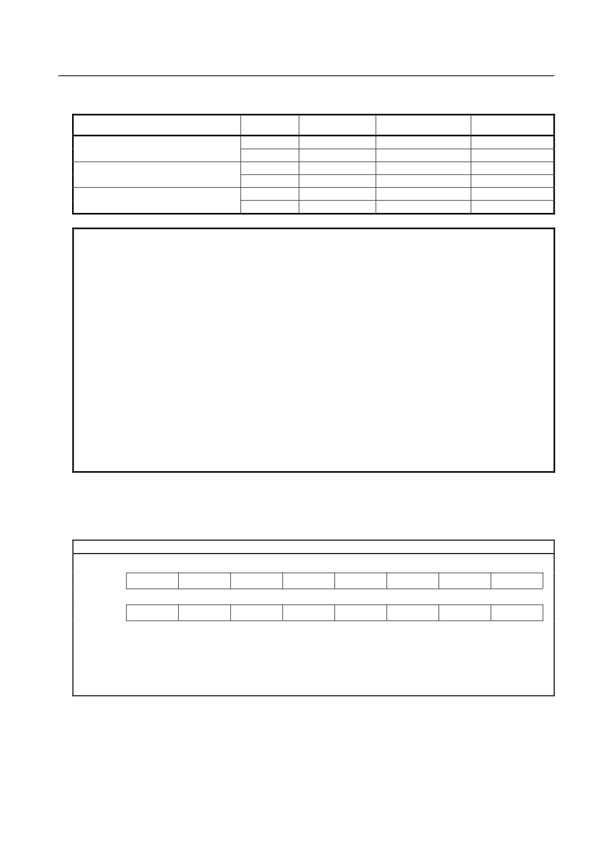
Variable number and variable name
Value
Field hold
Feedrate override
Exact stop
0
Enabled
Enabled
Enabled
1
Disabled
Enabled
Enabled
2
Enabled
Disabled
Enabled
#3004
3
Disabled
Disabled
Enabled
[#_CNTL2]
4
Enabled
Enabled
Disabled
5
Disabled
Enabled
Disabled
6
Enabled
Disabled
Disabled
7
Disabled
Disabled
Disabled
- 181 -
14.CUSTOM MACRO
PROGRAMMING
B-64304EN/02
In addition, the following variable names can be used to enable or disable feed hold, feedrate override,
and exact stop in G61 mode or by the G09 command, individually.
Variable number and variable name
Value
Feed hold
Feedrate override
Exact stop
0
Enabled
-
-
[#_M_FHD]
1
Disabled
-
-
0
-
Enabled
-
[#_M_OV]
1
-
Disabled
-
0
-
-
Enabled
[#_M_EST]
1
-
-
Disabled
NOTE
1 These system variables are provided to maintain compatibility with conventional
NC programs. It is recommended that functions provided by G63, G09, G61,
and other G codes be used to enable or disable feed hold, feedrate override,
and exact stop.
2 When the feed hold button is pressed during execution of a block for which feed
hold is disabled:
<1> If the feed hold button is kept pressed, operation stops after execution of
the block. When single block stop is disabled, however, operation does
not stop.
<2> If the pressed feed hold button is released, the feed hold lamp lights, but
operation does not stop until the end of the first block that was enabled.
3
#3004 is cleared by a reset.
4
If exact stop is disabled by #3004, the original exact stop position between
cutting feed and positioning block is not affected.
#3004 can temporarily
disable exact stop in G61 mode or by the G09 command between cutting feed
and cutting feed.
-
Settings #3005 (Attribute: R/W)
Settings can be read and written.
Binary values are converted to decimals.
#3005
#15
#14
#13
#12
#11
#10
#9
#8
Setting
FCV
#7
#6
#5
#4
#3
#2
#1
#0
Setting
SEQ
INI
ISO
TVC
#9 (FCV) : Whether to use the FANUC Series 15 program format conversion capability
#5 (SEQ) : Whether to automatically insert sequence numbers
#2 (INI)
:
Millimeter input or inch input
#1 (ISO) :
Whether to use EIA or ISO as the output code
#0 (TVC) :
Whether to make a TV check
-
Stop with a message #3006 (Attribute: W)
When "#3006=1 (MESSAGE);" is commanded in the macro, the program executes blocks up to the
immediately previous one and then stops. When a message of up to 60 characters with alphabet and
numerals, which is enclosed by a control-in character and control-out character, is programmed in the
same block, the message is displayed on the external operator message screen.
- 182 -
B-64304EN/02
PROGRAMMING
14.CUSTOM MACRO
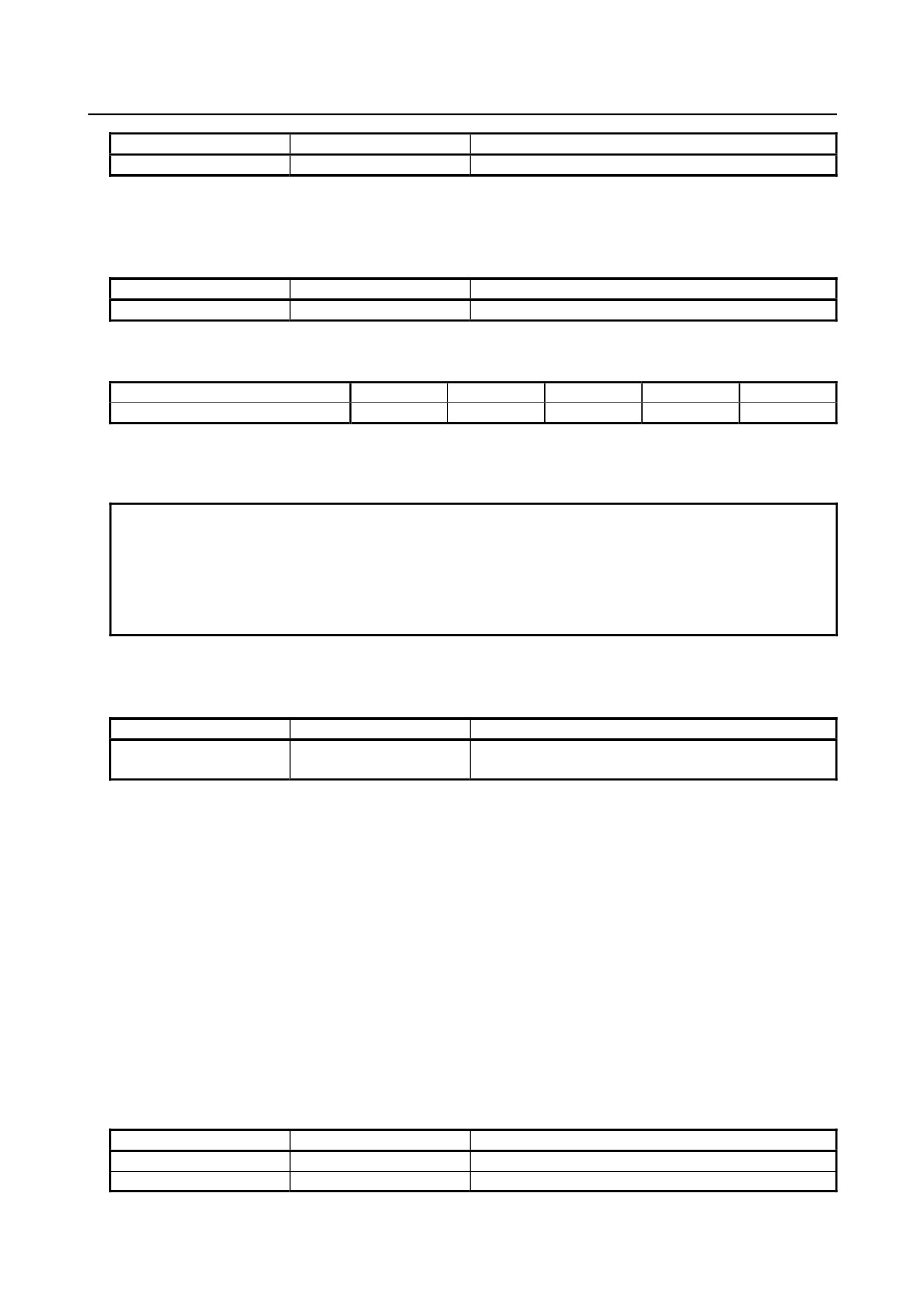
Variable number
Variable name
Description
#3006
[#_MSGSTP]
Stop with a message
-
Status of a mirror image #3007 (Attribute: R)
The status of an mirror image (setting or DI) at that point in time can be obtained for each axis by reading
#3007.
Variable number
Variable name
Description
#3007
[#_MRIMG]
Status of a mirror image
When the status is indicated in binary, each bit corresponds with an axis as follows.
Bit
4
3
2
1
0
nth axis
5
4
3
2
1
For the 5 bits, 0 indicates that a mirror image is disabled and 1 indicates that a mirror image is enabled.
[Example] When #3007 is 3, a mirror image is enabled for the 1st and 2nd axes.
NOTE
1 The status of a programmable mirror image is not reflected on this variable.
2 When the mirror image function is set for the same axis by the mirror image
signal and setting, the signal value and setting value are ORed and then output.
3 When mirror image signals for axes other than the controlled axes are turned on,
they are not read into system variable #3007.
-
Status during restart of a program #3008 (Attribute: R)
Whether a program is restarting can be determined by reading #3008.
Variable number
Variable name
Description
0: Program is not restarting.
#3008
[#_PRSTR]
1: Program is restarting.
-
Time #3011, #3012 (Attribute: R)
Year/month/date and hour/minute/second can be obtained by reading system variables #3011 and #3012.
This variable is read-only. To change year/month/date and hour/minute/second, use the timer screen.
[Example] May 20, 2004, PM 04:17:05
#3011 = 20040520
#3012 = 161705
-
Total number of parts and the number of required parts #3901 and #3902
(Attribute: R/W)
The number of required parts and the number of machined parts can be displayed on the screen by using
the operation time and part number displaying function. When the (total) number of machined parts
reaches the number of required parts, a signal indicating the fact is sent to the machine (PMC side).
The system variables can be used to read or write the total number of parts and the number of required
parts.
Variable number
Variable name
Description
#3901
[#_PRTSA]
Total number of parts
#3902
[#_PRTSN]
Number of required parts
- 183 -
14.CUSTOM MACRO
PROGRAMMING
B-64304EN/02
-
Type of tool compensation memory #3980 (Attribute: R)
M
System variable #3980 can be used to read the type of compensation memory.
Variable number
Variable name
Description
Types of tool compensation memory
#3980
[#_OFSMEM]
0: Tool compensation memory A
2: Tool compensation memory C
-
Main program number #4000 (Attribute: R)
System variable #4000 can be used to read the main program number regardless of the level of a
subprogram.
Variable number
Variable name
Description
#4000
[#_MAINO]
Main program number
NOTE
1 The main program number indicates the number of the program that is first
started.
2 When an O number is specified by MDI during execution of the main program or
when the second O number is specified in DNC mode, the value of #4000
changes to the specified O number. In addition, when no programs are
registered or when no O numbers are specified in DNC mode, the value of
#4000 changes to 0.
-
Modal information #4001-#4130, #4201-#4330, #4401-#4530 (Attribute: R)
The modal information specified before the previous block of the macro statement that reads system
variables #4001 to #4130 can be obtained in the block currently being looked ahead, by reading system
variables #4001 to #4130.
The modal information of the block currently being executed can be obtained by reading system variables
#4201 to #4330.
The modal information specified before the block interrupted by an interruption type custom macro by
reading system variables #4401 to #4530.
The unit used when it was specified is applied.
M
(Category:
<1> Previous block, <2> Running block, <3> Interrupted block)
Category
Variable number
Variable name
Description
<1>
#4001
[#_BUFG[1]]
<2>
#4201
[#_ACTG[1]]
Modal information (G code: group 1)
<3>
#4401
[#_INTG[1]]
:
:
:
:
:
:
:
:
<1>
#4030
[#_BUFG[30]]
Modal information
<2>
#4230
[#_ACTG[30]]
(G code: group 30)
<3>
#4430
[#_INTG[30]]
<1>
#4102
[#_BUFB]
<2>
#4302
[#_ACTB]
Modal information (B code)
<3>
#4502
[#_INTB]
- 184 -
B-64304EN/02
PROGRAMMING
14.CUSTOM MACRO
Category
Variable number
Variable name
Description
<1>
#4107
[#_BUFD]
<2>
#4307
[#_ACTD]
Modal information (D code)
<3>
#4507
[#_INTD]
<1>
#4108
[#_BUFE]
<2>
#4308
[#_ACTE]
Modal information (E code)
<3>
#4508
[#_INTE]
<1>
#4109
[#_BUFF]
<2>
#4309
[#_ACTF]
Modal information (F code)
<3>
#4509
[#_INTF]
<1>
#4111
[#_BUFH]
<2>
#4311
[#_ACTH]
Modal information (H code)
<3>
#4511
[#_INTH]
<1>
#4113
[#_BUFM]
<2>
#4313
[#_ACTM]
Modal information (M code)
<3>
#4513
[#_INTM]
<1>
#4114
[#_BUFN]
Modal information
<2>
#4314
[#_ACTN]
(sequence number N)
<3>
#4514
[#_INTN]
<1>
#4115
[#_BUFO]
Modal information
<2>
#4315
[#_ACTO]
(program number O)
<3>
#4515
[#_INTO]
<1>
#4119
[#_BUFS]
<2>
#4319
[#_ACTS]
Modal information (S code)
<3>
#4519
[#_INTS]
<1>
#4120
[#_BUFT]
<2>
#4320
[#_ACTT]
Modal information (T code)
<3>
#4520
[#_INTT]
<1>
#4130
[#_BUFWZP]
Modal information
<2>
#4330
[#_ACTWZP]
(additional workpiece coordinate system number P)
<3>
#4530
[#_INTWZP]
T
(Category:
<1> Previous block, <2> Running block, <3> Interrupted block)
Variable
Category
Variable name
Description
number
<1>
#4001
[#_BUFG[1]]
<2>
#4201
[#_ACTG[1]]
Modal information (G code: group 1)
<3>
#4401
[#_INTG[1]]
:
:
:
:
:
:
:
:
<1>
#4030
[#_BUFG[30]]
Modal information
<2>
#4230
[#_ACTG[30]]
(G code: group 30)
<3>
#4430
[#_INTG[30]]
<1>
#4108
[#_BUFE]
<2>
#4308
[#_ACTE]
Modal information (E code)
<3>
#4508
[#_INTE]
<1>
#4109
[#_BUFF]
<2>
#4309
[#_ACTF]
Modal information (F code)
<3>
#4509
[#_INTF]
<1>
#4113
[#_BUFM]
<2>
#4313
[#_ACTM]
Modal information (M code)
<3>
#4513
[#_INTM]
- 185 -