FANUC Series 0i-MODEL D, Series 0i Mate-MODEL D. OPERATOR'S MANUAL - page 4
5.FEED FUNCTIONS
PROGRAMMING
B-64304EN/02
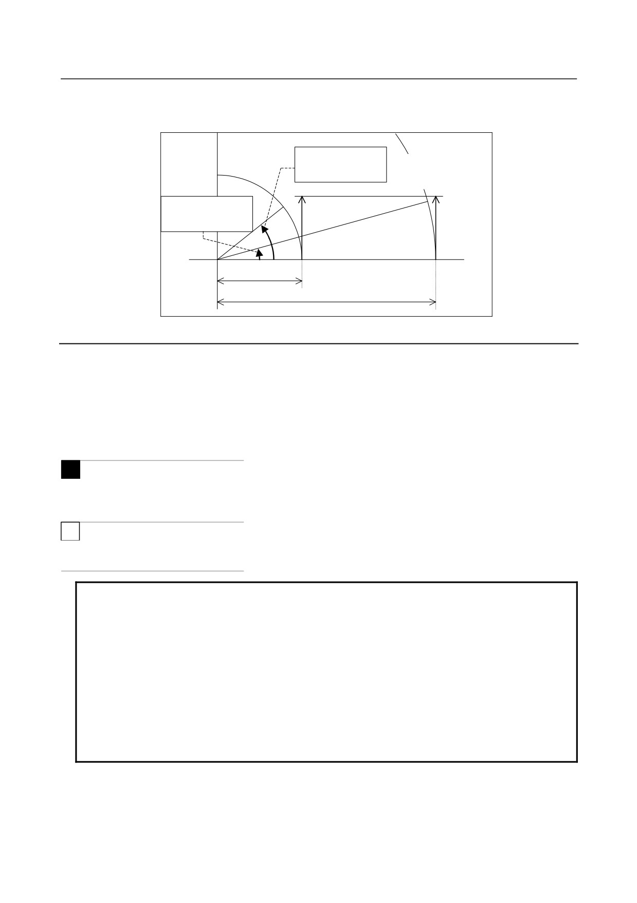
Therefore, the movement time becomes about 37.700(sec), and the rotation feedrate becomes about
15.915(deg/min). The feedrate on
36.000mm in an imaginary radius becomes
10.000mm/min at
instruction feedrate in Fig.5.5(a).
Rotation feedrate when
Instruction feedrate
10mm setting.:(1)
F=10mm/min
Rotation feedrate when
36mm setting.:(2)
10mm
36mm
Fig. 5.5 (a)
Limitation
This function corresponds only the linear interpolation(G01).
However, it doesn't correspond to the following functions.
• Feed per revolution
• Cylindrical interpolation
• Axis control by PMC
M
• Inverse time feed
• Normal direction control
T
• Polar coordinate interpolation
NOTE
1 When the parameter ROTx (No.1006#0) and the parameter RFDx (No.1408#0)
are 1, this function becomes effective.
2 The parameter RFDx (No.1408#0) and an imaginary radius (parameter No.1465)
of this function can be rewriting by the programmable parameter input(G10).
3 It moves at the maximum cutting feedrate when this function effectively and sets
0 in an imaginary radius (parameter No.1465) and it instructs only a rotary axis.
4 Note setting RFDx (No.1408#0) and an imaginary radius (parameter No.1465)
enough. Especially, a movement of axis quickens compared with this function
unused when small value is set to an imaginary radius.
5 In this function, the same value as the parameter value (No.1408, No.1465) of a
master axis is used with a slave axis, when it uses axis synchronous control.
- 66 -
B-64304EN/02
PROGRAMMING
5.FEED FUNCTIONS
5.6
DWELL
Format
M
G04 X_; or G04 P_;
X_ : Specify a time or spindle speed (decimal point permitted)
P_ : Specify a time or spindle speed (decimal point not permitted)
T
G04 X_ ; or G04 U_ ; or G04 P_ ;
X_ : Specify a time or spindle speed (decimal point permitted)
U_ : Specify a time or spindle speed (decimal point permitted)
P_ : Specify a time or spindle speed (decimal point not permitted)
Explanation
By specifying a dwell, the execution of the next block is delayed by the specified time.
(Dwell per
second)
By setting bit 1 (DWL) of parameter No. 3405 in the feed per revolution mode, the execution of the next
block is delayed until the rotation count of the spindle reaches the specified number.
(Dwell per
revolution)
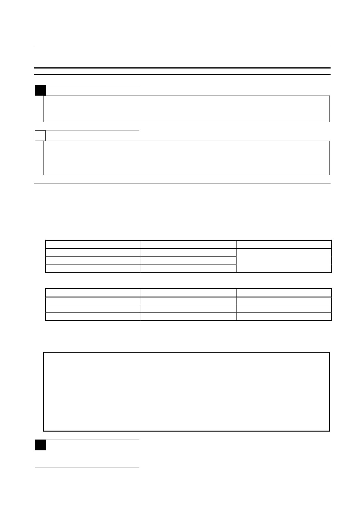
Table 5.6 (a) Command value range of the dwell time (Command by X or U)
Increment system
Command value range
Dwell time unit
IS-A
0.01 to 999999.99
IS-B
0.001 to 99999.999
sec or rev
IS-C
0.0001 to 9999.9999
Table 5.6 (b) Command value range of the dwell time (Command by P)
Increment system
Command value range
Dwell time unit
IS-A
1 to 99999999
0.01 sec or rev
IS-B
1 to 99999999
0.001 sec or rev
IS-C
1 to 99999999
0.0001 sec or rev
In the case of dwell per second, the specification unit for dwell time specified with P can be fixed at 0.001
second by setting bit 7 (DWT) of parameter No. 1015 to 1.
NOTE
1 When X, U, or P is specified without a decimal point, the specification unit does
not depend on inch/metric input. Depending on whether the X-axis is present,
the following increment system is used:
• When the X-axis is present
The increment system of the X-axis is used.
• When the X-axis is not present
The increment system of the reference axis is used.
2 When P is specified, bit 7 (IPR) of parameter No. 1004 exercises no influence.
M
Specify dwell also to make an exact check in the cutting mode (G64 mode).
If the specification of P and X is omitted, an exact stop occurs.
- 67 -
6.REFERENCE POSITION
PROGRAMMING
B-64304EN/02
6 REFERENCE POSITION
A CNC machine tool has a special position where, generally, the tool is exchanged or the coordinate
system is set, as described later. This position is referred to as a reference position.
Chapter 6, "REFERENCE POSITION", consists of the following sections:
6.1 REFERENCE POSITION RETURN
68
6.1
REFERENCE POSITION RETURN
Overview
-
Reference position
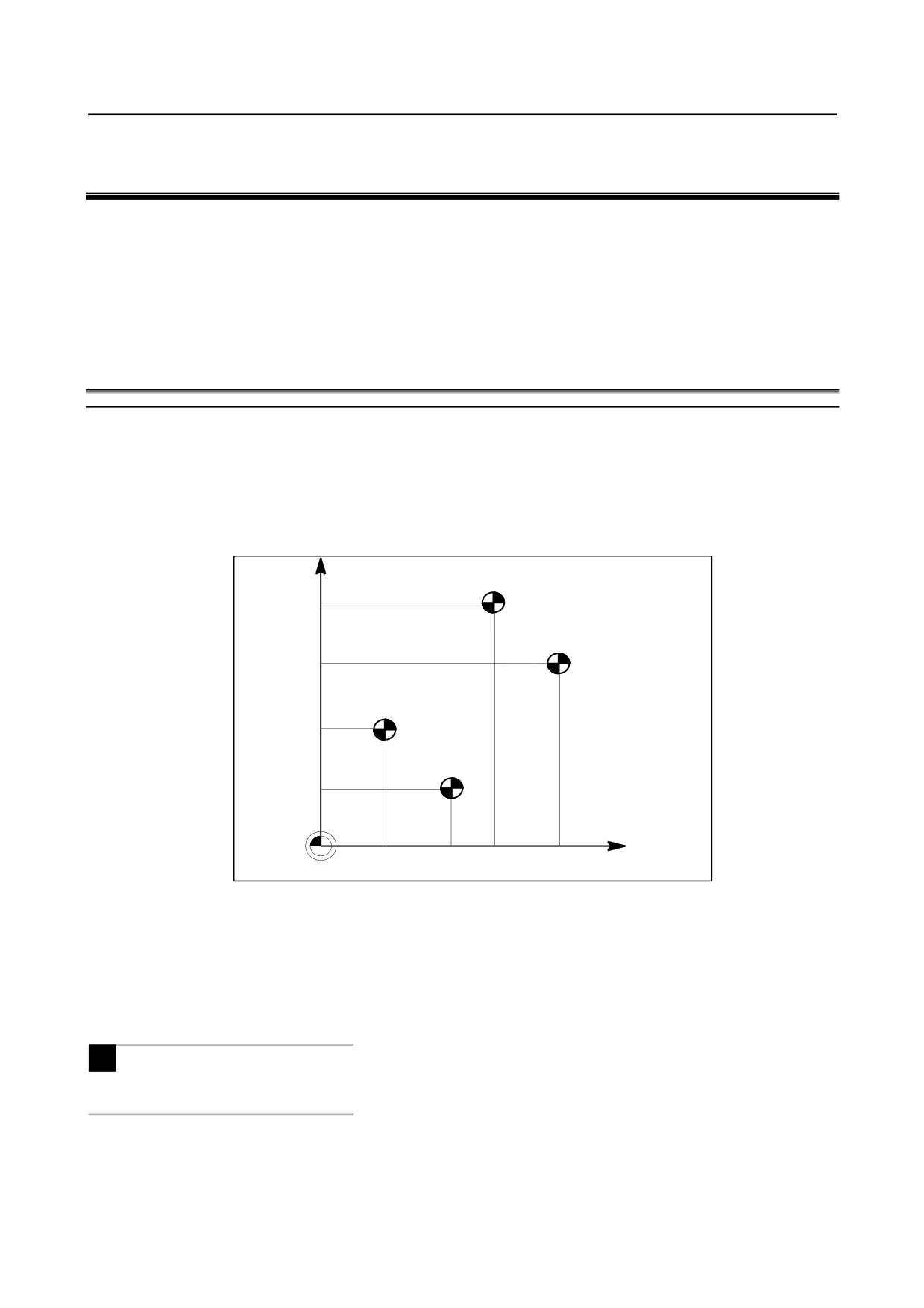
The reference position is a fixed position on a machine tool to which the tool can easily be moved by the
reference position return function.
For example, the reference position is used as a position at which tools are automatically changed. Up
to four reference positions can be specified by setting coordinates in the machine coordinate system in
parameters (No. 1240 to 1243).
Y
2nd reference position
3rd reference position
Reference position
4th reference
position
X
Machine zero point
Fig. 6.1 (a) Machine zero point and reference positions
-
Automatic reference position return (G28) and movement from the reference
position (G29)
The automatic reference position return (G28) function returns tools automatically to the reference
position via an intermediate position along a specified axis. When reference position return is
completed, the lamp for indicating the completion of reference position return goes on.
M
The return from reference position (G29) function moves tools from the reference position to a specified
position via an intermediate position along a specified axis.
- 68 -
B-64304EN/02
PROGRAMMING
6.REFERENCE POSITION
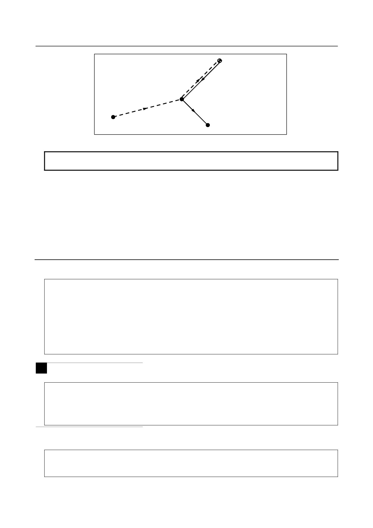
Automatic reference position return
(G28)
R (Reference position)
A → B → R
Movement from the reference position (G29)
R → B → C
B (Intermediate
position)
C (Destination of return from
A (Start position for reference
the reference position)
position return)
Fig. 6.1 (b) Reference position return and return form the reference position
NOTE
Movement from the reference position (G29) is enabled only for the M series.
-
Reference position return check (G27)
The reference position return check (G27) is the function which checks whether the tool has correctly
returned to the reference position as specified in the program. If the tool has correctly returned to the
reference position along a specified axis, the lamp for the axis for indicating the completion of reference
position return goes on.
If the tool has not reached the reference position, an alarm (PS0092) "ZERO RETURN CHECK (G27)
ERROR" is issued.
When no movement was made along the axis, whether the current position is the reference position is
checked.
Format
-
Automatic reference position return and 2nd/3rd/4th reference position return
G28 IP_;
Reference position return
G30 P2 IP_; 2nd reference position return (P2 can be omitted.)
G30 P3 IP_; 3rd reference position return
G30 P4 IP_; 4th reference position return
IP : Specify the intermediate position in the absolute coordinate system.
(absolute/incremental programming)
There is no need to calculate an actual travel distance between the intermediate position
and the reference position.
M
-
Movement from reference position
G29 IP_;
IP : Specify the destination of return from the reference position in the absolute coordinate
system. (absolute/incremental programming)
The intermediate position is determined by G28 or G30 specified immediately before
this command.
-
Reference position return check
G27 IP_;
IP : Specify positioning to the reference position in the absolute coordinate system so as to
return to the reference position. (absolute/incremental programming)
- 69 -
6.REFERENCE POSITION
PROGRAMMING
B-64304EN/02
Explanation
-
Automatic reference position return (G28)
Positioning to the intermediate or reference positions are performed at the rapid traverse rate of each axis.
Therefore, for safety, the compensation functions, such as the cutter compensation, tool nose radius
compensation, tool length compensation, and tool offset, should be cancelled before executing this
command.
The coordinates for the intermediate position are stored in the CNC for the axes for which a value is
specified in a G28 block. For the other axes, the previously specified coordinates are used.
(Example)
N1 G28 X40.0 ;
(The tool moves to the reference position along the X-axis and the intermediate position (X40.0) is
stored.)
N2 G28 Y60.0 ;
(The tool moves to the reference position along the Y-axis and the intermediate position (Y60.0) is
stored.)
N3 G29 X10.0 Y20.0 ;
(The tool moves to the position specified with G29 via the intermediate position (X40.0 Y60.0)
previously specified with G28 along the X-axis and Y-axis.)
-
2nd, 3rd, and 4th reference position return (G30)
The 2nd, 3rd, and 4th reference position return (G30) function can be used after the reference positions
are established.
The G30 command is generally used when the automatic tool changer (ATC) position differs from the
reference position.
M
-
Movement from the reference position (G29)
This function is executed after the tool is returned to the reference position by G28 or G30.
For incremental programming, the command value specifies the incremental value from the intermediate
point.
The tool moves to the intermediate and specified positions at the feedrate specified with a parameter.
When the workpiece coordinate system is changed after the tool reaches the reference position through
the intermediate point by the G28 command, the intermediate point also shifts to a new coordinate system.
If G29 is then commanded, the tool moves to the commanded position through the intermediate point
which has been shifted to the new coordinate system.
The same operations are performed also for G30 command.
After the power is turned on, an alarm (PS0305) is issued if an attempt is made to execute G29
(movement from the reference position) before G28 (automatic reference position return) or G30 (2nd,
3rd, and 4th reference position return) is executed.
-
Reference position return check (G27)
G27 command positions the tool at rapid traverse rate. If the tool reaches the reference position, the
lamp for indicating the completion of reference position return lights up.
When the tool returns to the reference position along only one axis, the lamp for the axis for indicating
the completion of reference position return lights up.
After positioning, if the tool has not reached the reference position along a specified axis, an alarm
(PS0092) "ZERO RETURN CHECK (G27) ERROR" is issued.
When no movement was made along the axis, whether the current position is the reference position is
checked.
- 70 -
B-64304EN/02
PROGRAMMING
6.REFERENCE POSITION
-
Setting of the reference position return feedrate
Before a coordinate system is established with the first reference position return after power-on, the
manual and automatic reference position return feedrates and automatic rapid traverse rate conform to the
setting of parameter No. 1428 for each axis.
After a reference position is established upon the completion of reference position return, the manual
reference position return feedrate conforms to the setting of the parameter No. 1428 for each axis.
NOTE
1
To this feedrate, a rapid traverse override (F0,25%,50%,100%) is applied, for
which the setting is 100%.
2
After a reference position has been established upon the completion of reference
position return, the automatic reference position return feedrate will conform to
the ordinary rapid traverse rate.
3
When a value is set for parameter No. 1428, the feedrates conform to the
parameter settings shown below.
Before a coordinate system
After a coordinate system
is established
is established
Automatic reference position return (G28)
No. 1428
No.1420
Automatic rapid traverse (G00)
No.1428
No.1420
Manual reference position return (*1)
No.1428
No.1428 (*3)
Manual rapid traverse rate
No.1423 (*2)
No.1424
1420: Rapid traverse rate
1423: Jog feedrate
1424: Manual rapid traverse rate
1428: Reference position return feedrate
When parameter No. 1428 is set to 0, the feedrates conform to the parameter
settings shown below.
Before a coordinate system
After a coordinate system
is established
is established
Automatic reference position return (G28)
No. 1420
No.1420
Automatic rapid traverse (G00)
No.1420
No.1420
Manual reference position return (*1)
No.1424
No.1424 (*3)
Manual rapid traverse rate
No.1423 (*2)
No.1424
*1 By using JZR (bit 2 of parameter No. 1401), the manual reference position
return feedrate can always be set as a jog feedrate.
*2 When RPD (bit 0 of parameter No. 1401) is 1, the setting of parameter No.
1424 (manual rapid traverse rate) is used.
When the setting of parameter No. 1424 (manual rapid traverse rate) is 0,
parameter No. 1420 (rapid traverse rate) is used.
*3 When reference position return without dogs is performed in rapid traverse
mode, or when manual reference position return is performed in rapid
traverse mode regardless of deceleration dogs after a reference position is
established, the reference position return feedrate for each of these
functions (setting of DLF (bit 1 of parameter No. 1404)) is used.
Limitation
-
Status the machine lock being turned on
The lamp for indicating the completion of reference position return does not go on when the machine lock
is turned on, even when the tool has automatically returned to the reference position. In this case, it is
not checked whether the tool has returned to the reference position even when a reference position return
check command is specified.
- 71 -
6.REFERENCE POSITION
PROGRAMMING
B-64304EN/02
-
When automatic reference position return (G28) is executed if no reference
position is established
When automatic reference position return (G28) is executed if no reference position is established,
movement from the intermediate position in a reference position direction is the same as that in manual
reference position return.
(This movement is referred to as a low-speed type of automatic reference position return (G28).)
In this case, the tool moves in the direction for reference position return specified in parameter ZMIx (bit
5 of No. 1006). Therefore the specified intermediate position must be a position to which reference
position return is possible.
NOTE
When automatic reference position return (G28) is executed after a reference
position is established, positioning is performed from the intermediate position to
the reference position. This movement is referred to as a high-speed type of
automatic reference position return (G28).
-
Reference position return check in an offset mode
In an offset mode, the position to be reached by the reference position return check is the position
obtained by adding the offset value.
Therefore, if the position with the offset value added is not the reference position, the lamp for indicating
the completion of reference position return does not light up, but an alarm is displayed instead.
Accordingly, cancel compensation and specify G27 in ordinary cases.
-
Lighting the lamp when the programmed position does not coincide with the
reference position
When the machine tool system is an inch system with metric input, the lamp for indicating the completion
of reference position return may also light up even if the programmed position is shifted from the
reference position by the least setting increment. This is because the least setting increment of the
machine tool system is smaller than its least command increment.
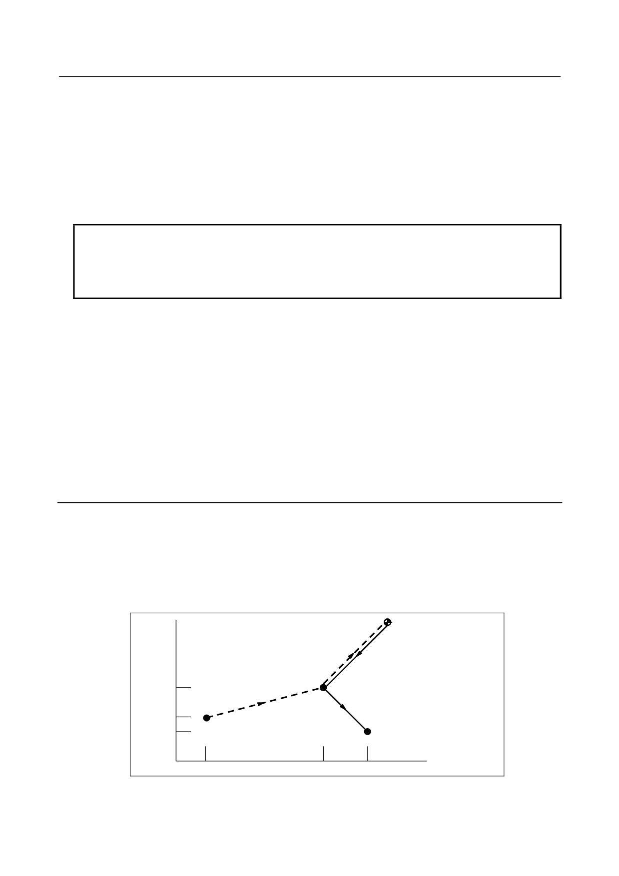
Example
G28G90X1000.0Y500.0 ;
(Programs movement from A to B. The tool moves to reference position
R via intermediate position B.)
T111 ;
M06 ;
(Changing the tool at the reference position)
G29X1300.0Y200.0 ;
(Programs movement from B to C. The tool moves from reference position
R to C specified with G29 via intermediate position B.)
Automatic reference position return (G28)
R (Reference position)
Y
A → B → R
Movement from the reference position (G29)
R → B → C
B (Intermediate
position)
500
C (Destination of return from the
300
reference position)
A (Start position for reference
200
position return)
200
1000
1300
X
Fig. 6.1 (c) Reference position return and movement from the reference position
- 72 -
B-64304EN/02
PROGRAMMING
7.COORDINATE SYSTEM
7 COORDINATE SYSTEM
By teaching the CNC a desired tool position, the tool can be moved to the position. Such a tool position is
represented by coordinates in a coordinate system. Coordinates are specified using program axes.
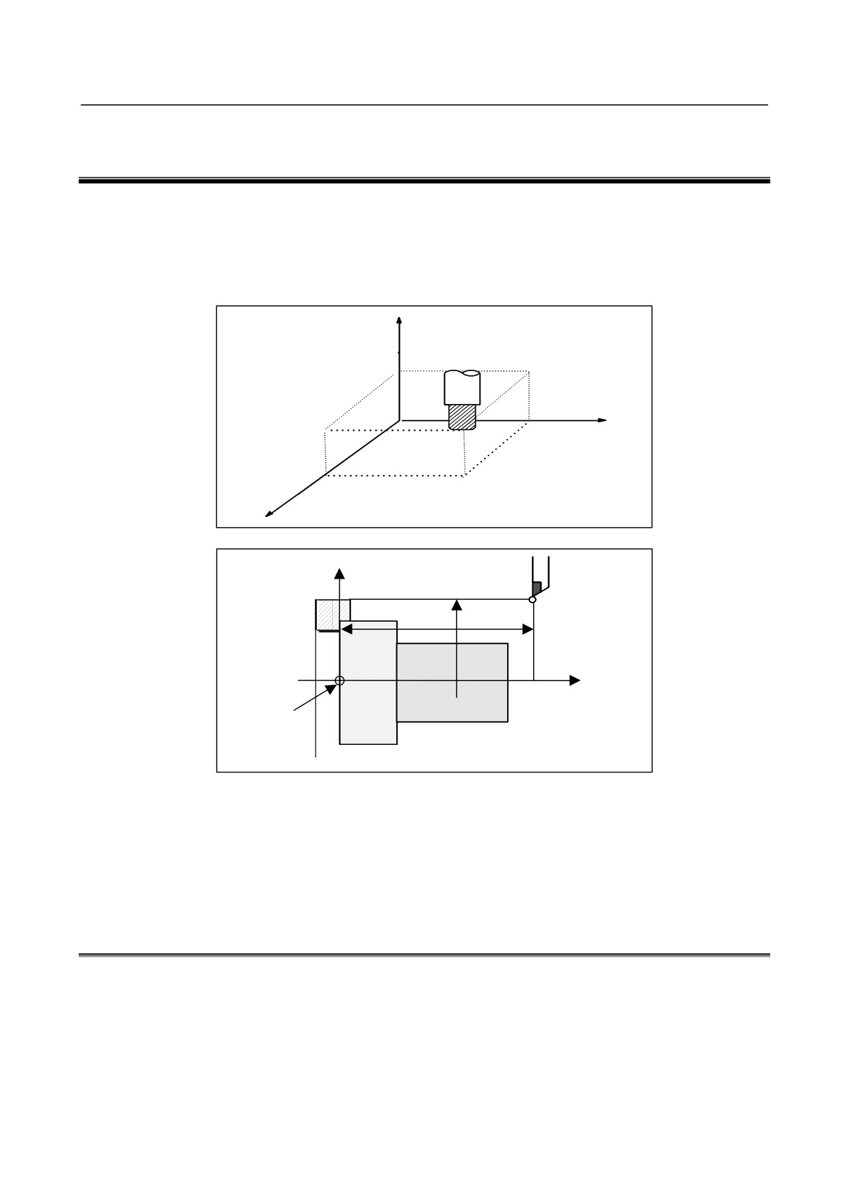
When three program axes, the X-axis, Y-axis, and Z-axis, are used, coordinates are specified as follows:
X_Y_Z_
This command is referred to as a dimension word.
• For milling machining (Tool position specified by X40.0Y50.0Z25.0 )
Z
25.0
Y
50.0
40.0
X
• For lathe cutting (Tool position specified by X50.0 Z40.0)
X
40.0
50.0
Z
Zero point
Coordinates are specified in one of following three coordinate systems:
(1) Machine coordinate system
(2) Workpiece coordinate system
(3) Local coordinate system
The number of the axes of a coordinate system varies from one machine to another. So, in this manual, a
dimension word is represented as IP_.
7.1
MACHINE COORDINATE SYSTEM
The point that is specific to a machine and serves as the reference of the machine is referred to as the
machine zero point. A machine tool builder sets a machine zero point for each machine.
A coordinate system with a machine zero point set as its origin is referred to as a machine coordinate
system.
A machine coordinate system is set by performing manual reference position return after power-on (see
III-3.1). A machine coordinate system, once set, remains unchanged until the power is turned off.
The reference position is not always the origin of the machine coordinate system.
(See "Setting a machine coordinate system" described later.)
- 73 -

7.COORDINATE SYSTEM
PROGRAMMING
B-64304EN/02
Format
G53 IP_ (P1) ;
IP_: Absolute dimension word
P1: Enables the high-speed G53 function.
Explanation
-
Selecting a machine coordinate system (G53)
When a command is specified the position on a machine coordinate system, the tool moves to the position
by rapid traverse. G53, which is used to select a machine coordinate system, is a one-shot G code; that
is, it is valid only in the block in which it is specified on a machine coordinate system. Specify an
absolute command for G53. When an incremental command is specified, the G53 command is ignored.
When the tool is to be moved to a machine-specific position such as a tool change position, program the
movement in a machine coordinate system based on G53.
-
High-speed G53 function
This function enables the inter-rapid traverse block overlap function between machine coordinate
selection command (G53) and positioning (rapid traverse) command (G00) blocks, thus making it
possible to execute the next rapid traverse command (G00) without decelerating to a stop at the end of the
machine coordinate selection command (G53). Therefore, high-speed positioning is available even
when the machine coordinate selection command (G53) is used.
Specifying P1 in a G53 block enables the high-speed G53 function.
Limitation
-
Cancel of the compensation function
When the G53 command is specified, cancel the compensation functions such as the cutter compensation,
tool length compensation, tool nose radius compensation, and tool offset.
-
G53 specification immediately after power-on
Since the machine coordinate system must be set before the G53 command is specified, at least one
manual reference position return or automatic reference position return by the G28 command must be
performed after the power is turned on. This is not necessary when an absolute-position detector is
attached.
-
Blocks in which the high-speed G53 function is usable
The high-speed G53 function is usable in the following combinations of commands:
• G53 → G00
• G53 → G53
The high-speed G53 function is unusable in the following combination of commands:
• G00 → G53
-
Specification in the same block
M
Commands G50/G51 (scaling), G50.1/G51.1 (programmable mirror image), and G68/G69 (coordinate
system rotation) cannot be specified in the same block where the G53 command is specified.
Note
NOTE
G53 is a G code for disabling buffering.
- 74 -
B-64304EN/02
PROGRAMMING
7.COORDINATE SYSTEM
Reference
-
Setting a machine coordinate system
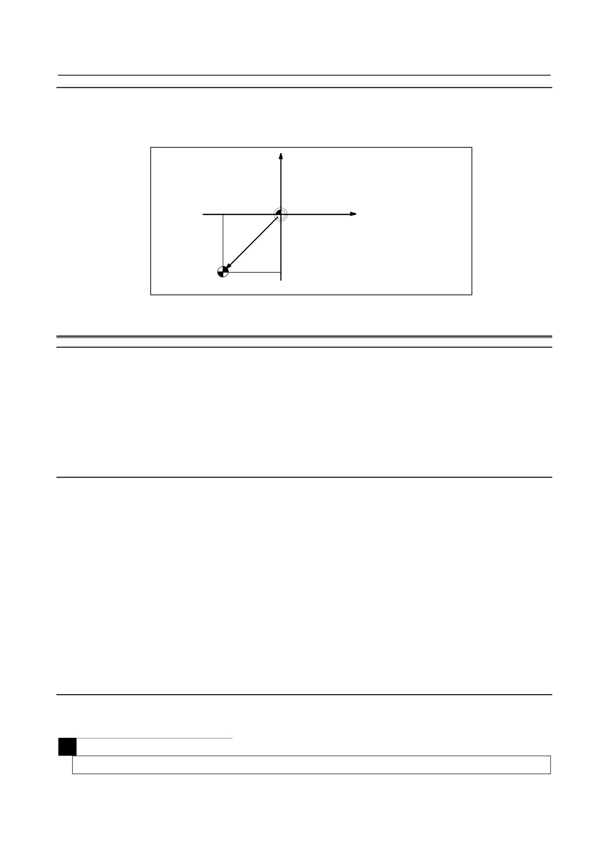
When manual reference position return is performed after power-on, a machine coordinate system is set
so that the reference position is at the coordinate values of (α, β) set using parameter No.1240.
Machine coordinate system
Machine zero point
β
α
Reference position
7.2
WORKPIECE COORDINATE SYSTEM
Overview
A coordinate system used for machining a workpiece is referred to as a workpiece coordinate system. A
workpiece coordinate system is to be set with the CNC beforehand (setting a workpiece coordinate
system).
A machining program sets a workpiece coordinate system (selecting a workpiece coordinate system).
A set workpiece coordinate system can be changed by shifting its origin
(changing a workpiece
coordinate system).
7.2.1
Setting a Workpiece Coordinate System
A workpiece coordinate system can be set using one of three methods:
(1) Method using a workpiece coordinate system setting G code
A workpiece coordinate system is set by specifying a value in the program after a workpiece
coordinate system setting G code.
(2) Automatic setting
If bit 0 of parameter ZPR No. 1201 is set to 1, a workpiece coordinate system is automatically set
when manual reference position return is performed (see III-3.1.).
When using the workpiece coordinate system function (bit 0 (NWZ) of parameter No. 8136 is 0),
this method is disabled.
(3) Method using a workpiece coordinate system selection G code
Six workpiece coordinate systems can be set beforehand using the MDI panel. Program commands
G54 to G59 can be used to select the workpiece axis to be used.
(see III-12.3.4.)
When using an absolute command, establish the workpiece coordinate system in any of the above ways.
Format
-
Setting a workpiece coordinate system
M
G92 IP_ ;
- 75 -
7.COORDINATE SYSTEM
PROGRAMMING
B-64304EN/02
T
G50 IP_ ;
Explanation
A workpiece coordinate system is set so that a point on the tool, such as the tool tip, is at specified
coordinates.
M
If a coordinate system is set using G92 during tool length offset, a coordinate system in which the
position before offset matches the position specified in G92 is set. Cutter compensation is cancelled
temporarily with G92.
T
If IP_ is an incremental command value, the workpiece coordinate system is defined so that the current
tool position coincides with the result of adding the specified incremental value to the coordinates of the
previous tool position. If a coordinate system is set using G50 during offset, a coordinate system in
which the position before offset matches the position specified in G50 is set.
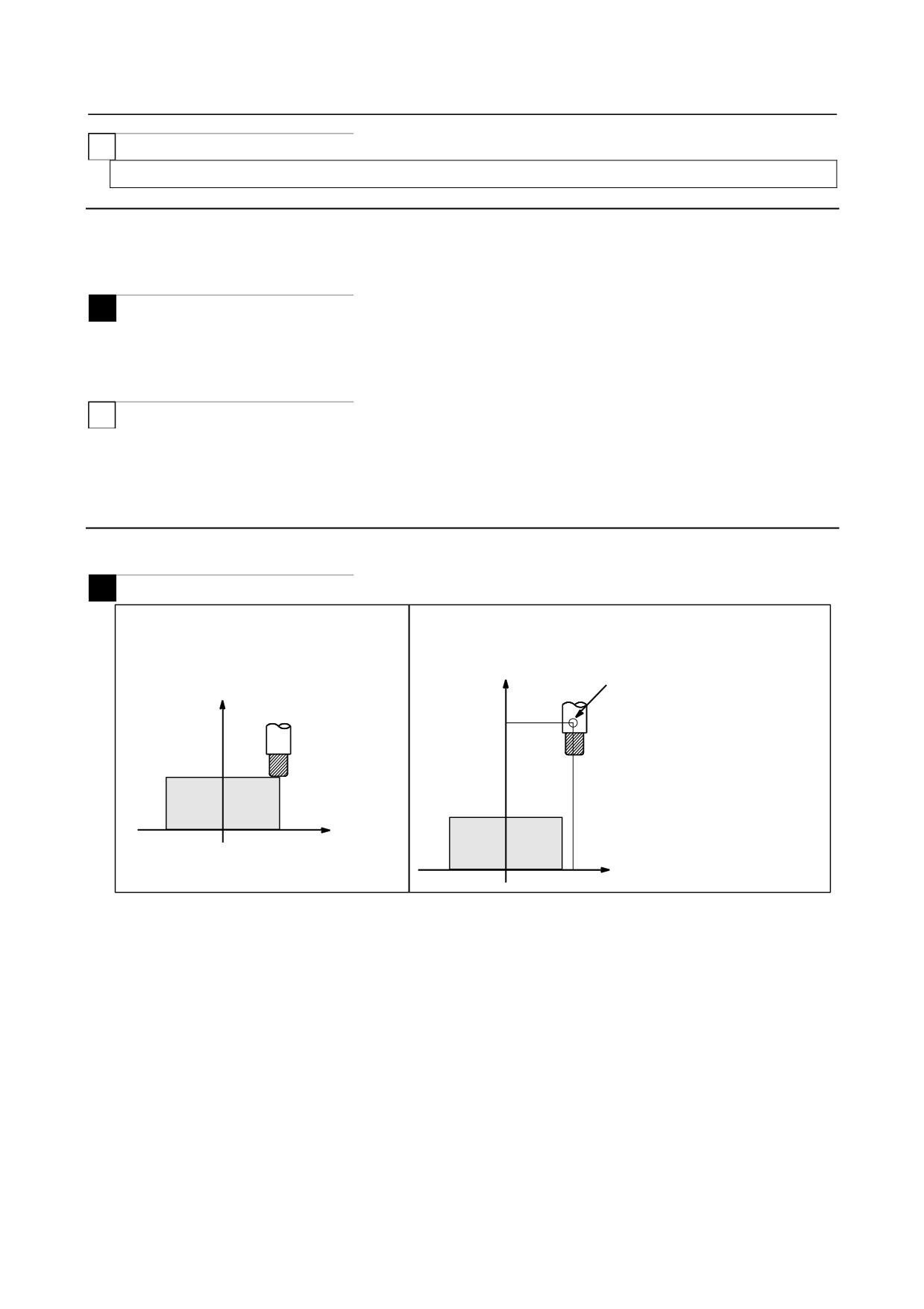
Example
M
(Example 1)
(Example 2)
Setting the coordinate system by the
Setting the coordinate system by the G92X600.0Z1200.0; command (The
G92X25.2Z23.0; command (The tool tip is the start
base point on the tool holder is the start point for the program.)
point for the program.)
Z
Base point
Z
1200.0
If an absolute command is issued, the
base point moves to the commanded
23.0
position. In order to move the tool tip to
the commanded position, the difference
from the tool tip to the base point is
compensated by tool length offset.
X
0
25.2
X
0
600.0
- 76 -
B-64304EN/02
PROGRAMMING
7.COORDINATE SYSTEM
T
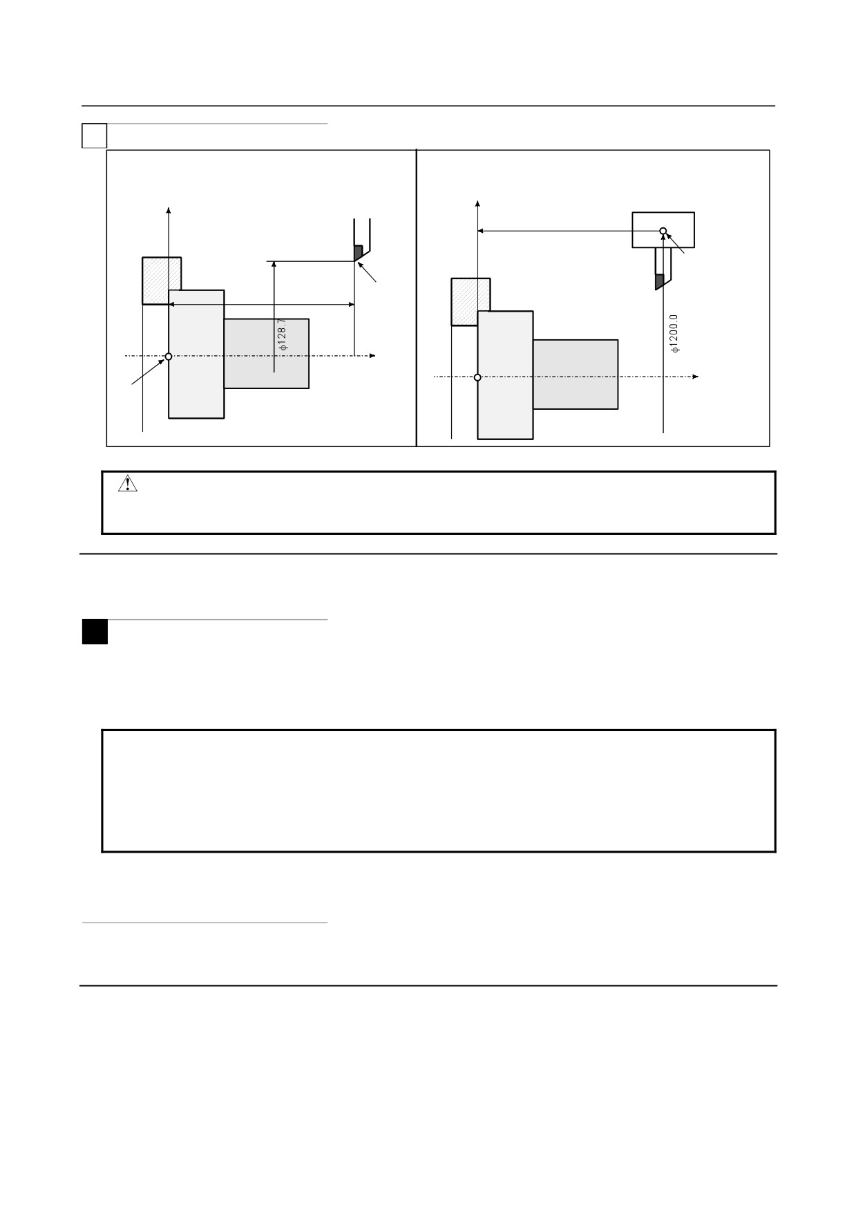
(Example 1)
(Example 2)
Setting the coordinate system by the G50X128.7Z375.1;
Setting the coordinate system by the G50X1200.0Z700.0;
command (Diameter designation) (The tool nose is the
command (Diameter designation) (The base point on the turret is
start point for the program.)
the start point for the program.)
X
X
700.0
Start point
(base point)
Start point
375.1
Z
Z
Origin
CAUTION
The set workpiece coordinate system depends on diameter programming or
radius programming.
Notes
-
Command for setting a workpiece coordinate system in the tool length
compensation mode
M
Executing a workpiece coordinate system setting G code command (G92) presets a coordinate system in
such a way that the specified position will be a pre-compensation position.
However, this G code cannot be used together with a block where tool length compensation vectors vary.
If it is used, alarm PS5391 is issued. For example, it cannot be used together with the following blocks.
EXAMPLE
1 Block in which G43/G44 is issued
2 Block which is in the G43 or G44 mode and in which an H code is issued
3 Block which is in the G43 or G44 mode and in which G49 is issued
4 Block in which, in the G43 or G44 mode, compensation vectors are canceled
using a G code such as G28 or G53 and then resumed again
When presetting a workpiece coordinate system, using the workpiece coordinate system setting G code,
do not stop in the previous block to change a tool length compensation offset selected, for example, with
the MDI.
7.2.2
Selecting a Workpiece Coordinate System
The user can choose from set workpiece coordinate systems as described below.
(For information about
the methods of setting, see II-7.2.1.)
(1) Once a workpiece coordinate system is set by a workpiece coordinate system setting G code or by
automatic workpiece coordinate system setting, absolute commands indicate positions in the
workpiece coordinate system.
(2) Choosing from six workpiece coordinate systems set using the MDI panel
- 77 -
7.COORDINATE SYSTEM
PROGRAMMING
B-64304EN/02
By specifying a G code from G54 to G59, one of the workpiece coordinate systems 1 to 6 can be
selected.
G54 : Workpiece coordinate system 1
G55 : Workpiece coordinate system 2
G56 : Workpiece coordinate system 3
G57 : Workpiece coordinate system 4
G58 : Workpiece coordinate system 5
G59 : Workpiece coordinate system 6
Workpiece coordinate system 1 to 6 are established after reference position return after the power is
turned on. When the power is turned on, G54 coordinate system is selected.
When bit 2 (G92) of parameter No. 1202 is set to 1, executing the workpiece coordinate system setting
G92 code command results in the issue of an alarm PS0010. This is designed to prevent the user from
confusing coordinate systems.
CAUTION
The set workpiece origin offset value depends on diameter programming or
radius programming.
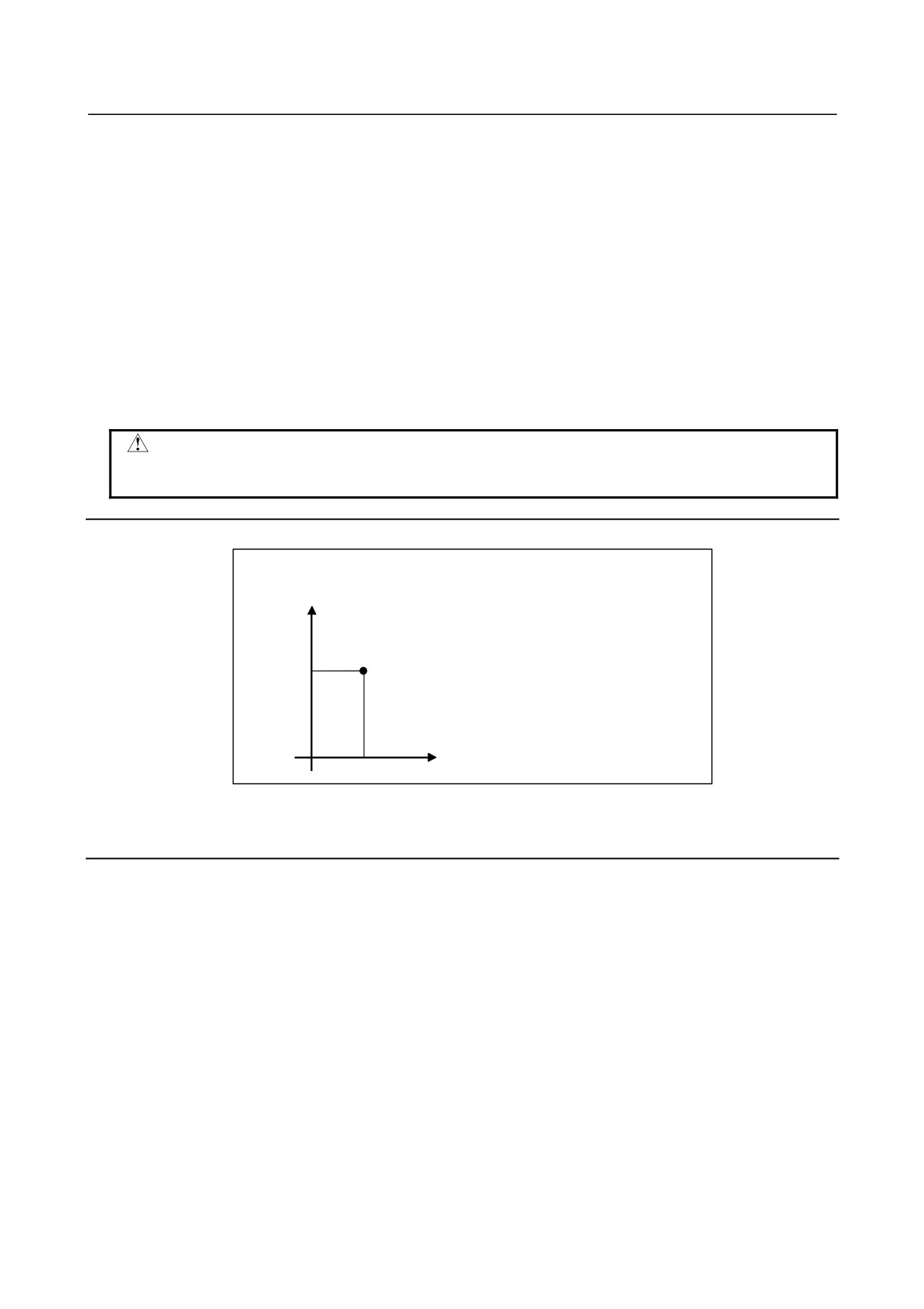
Example
G90 G55 G00 X40.0 Y100.0 ;
Y
Workpiece coordinate system 2 (G55)
100.0
In this example, positioning is made to
positions
(X=40.0, Y=100.0) in workpiece
coordinate system 2.
X
40.
Fig. 7.2.2 (a)
7.2.3
Changing Workpiece Coordinate System
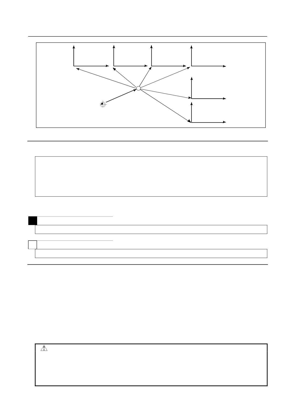
The six workpiece coordinate systems specified with G54 to G59 can be changed by changing an external
workpiece origin offset value or workpiece origin offset value.
Three methods are available to change an external workpiece origin offset value or workpiece origin
offset value.
(1) Inputting from the MDI panel (see III-12.3.4)
(2) Programming (using a programmable data input G code or a workpiece coordinate system setting G
code)
(3) Using the external data input function
An external workpiece origin offset value can be changed by input signal to CNC. Refer to machine
tool builder's manual for details.
- 78 -
B-64304EN/02
PROGRAMMING
7.COORDINATE SYSTEM
Workpiece
Workpiece
Workpiece
Workpiece
coordinate system 1
coordinate system 2
coordinate system 3
coordinate system 4
(G54)
(G55)
(G56)
(G57)
ZOFS2
ZOFS3
ZOFS4
ZOFS1
Workpiece coordinate
ZOFS5
system 5
(G58)
EXOFS
Machine zero point
ZOFS6
Workpiece coordinate
system 6
(G59)
EXOFS : External workpiece origin offset value
ZOFS1 to ZOFS6 : Workpiece origin offset value
Fig. 7.2.3 (a) Changing an external workpiece origin offset value or workpiece origin offset value
Format
-
Changing by inputting programmable data
G10 L2 Pp IP_;
p=0
: External workpiece origin offset value
p=1 to 6
: Workpiece origin offset value correspond to workpiece coordinate system 1 to 6
IP_ : For an absolute command, workpiece origin offset for each axis.
For an incremental command, value to be added to the set workpiece origin offset for
each axis (the result of addition becomes the new workpiece origin offset).
-
Changing by setting a workpiece coordinate system
M
G92 IP_ ;
T
G50 IP_ ;
Explanation
-
Changing by inputting programmable data
By specifying a programmable data input G code, the workpiece origin offset value can be changed for
each workpiece coordinate system.
-
Changing by setting a workpiece coordinate system
By specifying a workpiece coordinate system setting G code, the workpiece coordinate system (selected
with a code from G54 to G59) is shifted to set a new workpiece coordinate system so that the current tool
position matches the specified coordinates (IP_).
Then, the amount of coordinate system shift is added to all the workpiece origin offset values. This
means that all the workpiece coordinate systems are shifted by the same amount.
CAUTION
When a coordinate system is set with workpiece coordinate system setting G92
code command after an external workpiece origin offset value is set, the
coordinate system is not affected by the external workpiece origin offset value.
When G92X100.0Z80.0; is specified, for example, the coordinate system having
its current tool reference position at X = 100.0 and Z = 80.0 is set.
- 79 -
7.COORDINATE SYSTEM
PROGRAMMING
B-64304EN/02
T
If IP is an incremental command value, the workpiece coordinate system is defined so that the current tool
position coincides with the result of adding the specified incremental value to the coordinates of the
previous tool position.
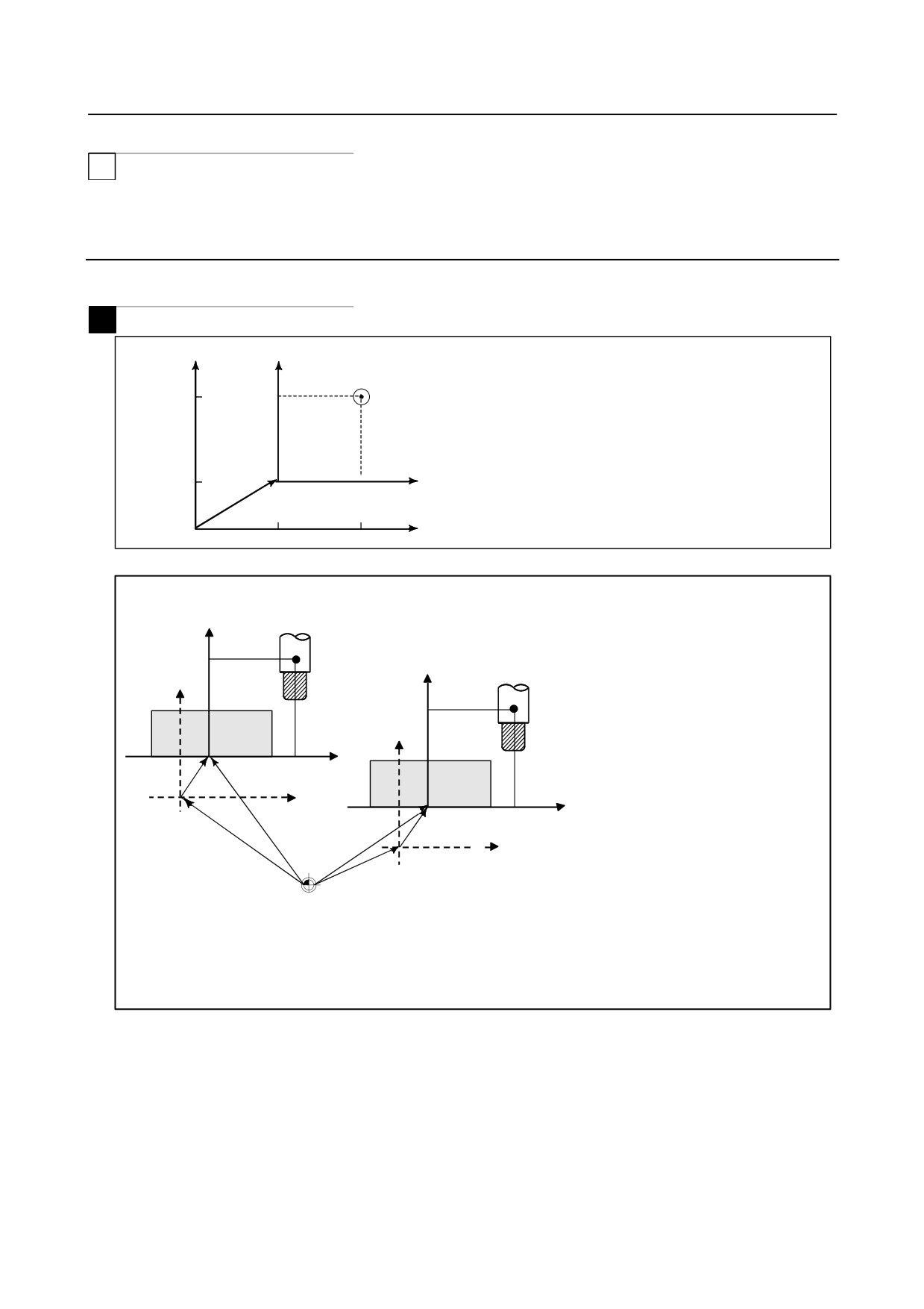
(Coordinate system shift)
Example
M
Y
Y’
G54 workpiece coordinate system
If G92X100Y100; is commanded when the tool is positioned
160
100
Tool position
at (200, 160) in G54 mode, workpiece coordinate system 1
(X' - Y') shifted by vector A is created.
A
X’
New workpiece coordinate system
60
100
X
Original workpiece coordinate system
100
200
G54 workpiece coordinate system
Suppose that a G54 workpiece coordinate
system is specified. Then, a G55 workpiece
Z'
coordinate system where the black circle on
G55 workpiece coordinate system
the tool (figure at the left) is at (600.0,1200.0)
1200.0
can be set with the following command if the
Z'
relative relationship between the G54
workpiece coordinate system and G55
Z
1200.0
workpiece coordinate system is set correctly:
G92X600.0Z1200.0;
Also, suppose that pallets are loaded at two
Z
different positions. If the relative relationship
X'
of the coordinate systems of the pallets at the
A
600.0
two positions is correctly set by handling the
coordinate systems as the G54 workpiece
X
coordinate system and G55 workpiece
X'
600.0
coordinate system, a coordinate system shift
B
with G92 in one pallet causes the same
AA
coordinate system shift in the other pallet.
X
This means that workpieces on two pallets
C
can be machined with the same program just
by specifying G54 or G55.
X' - Z'
New workpiece coordinate system
X - Z
Original workpiece coordinate system
A : Offset value created by G92
B : Workpiece origin offset value in the G54
C : Workpiece origin offset value in the G55
- 80 -
B-64304EN/02
PROGRAMMING
7.COORDINATE SYSTEM
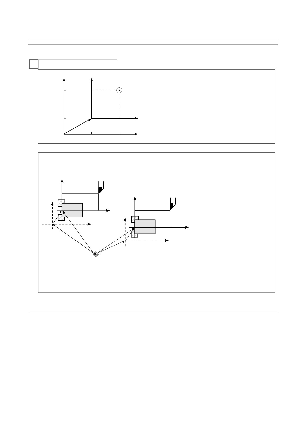
Example
T
X
X'
G54 workpiece coordinate system
If G50X100Z100; is commanded when the tool is
160
100
Tool position
positioned at
(200,
160) in G54 mode, workpiece
coordinate system 1 (X' - Z') shifted by vector A is
created.
60
Z'
New workpiece coordinate system
A
100
Z
Original workpiece coordinate system
100
200
Suppose that a G54 workpiece coordinate
G54 workpiece coordinate system
system is specified. Then, a G55
X'
workpiece coordinate system where the
black tool nose point on the tool (figure at
G55 workpiece coordinate system
the left) is at (600.0,1200.0) can be set
with the following command if the relative
X'
600.0
relationship between the G54 workpiece
coordinate system and G55 workpiece
X
coordinate system is set correctly:
G50X600.0Z1200.0;
Z'
600.0
1200.0
Also, suppose that loading is performed at
A
X
two different places and that the G54 and
Z
G55 workpiece coordinate systems are
Z'
set for these two places. If the relative
1200.0
relationship between the coordinate
B
A
systems in the two places is correctly set,
Z
a coordinate system shift with G50 in one
loading place causes the same
C
coordinate system shift in the other
loading place. This means that
workpieces on the two loading positions
X' - Z'
New workpiece coordinate system
can be machined with the same program
X - Z
Original workpiece coordinate system
just by specifying G54 or G55.
A : Offset value created by G50
B : Workpiece origin offset value in G54
C : Workpiece origin offset value in G55
7.2.4
Workpiece Coordinate System Preset (G92.1)
The workpiece coordinate system preset function presets a workpiece coordinate system shifted by
manual intervention to the pre-shift workpiece coordinate system. The latter system is displaced from
the machine zero point by a workpiece origin offset value.
There are two methods for using the workpiece coordinate system preset function. One method uses a
programmed command. The other uses MDI operations on the absolute position display screen, relative
position display screen, and overall position display screen (see III-12.1.4).
- 81 -
7.COORDINATE SYSTEM
PROGRAMMING
B-64304EN/02
Format
M
G92.1 IP 0 ;
IP 0 : Specifies axis addresses subject to the workpiece coordinate system preset
operation. Axes that are not specified are not subject to the preset operation.
T
G50.3 IP 0 ;
(G92.1 IP 0; for G code system B or C)
IP 0 : Specifies axis addresses subject to the workpiece coordinate system preset
operation. Axes that are not specified are not subject to the preset operation.
Explanation
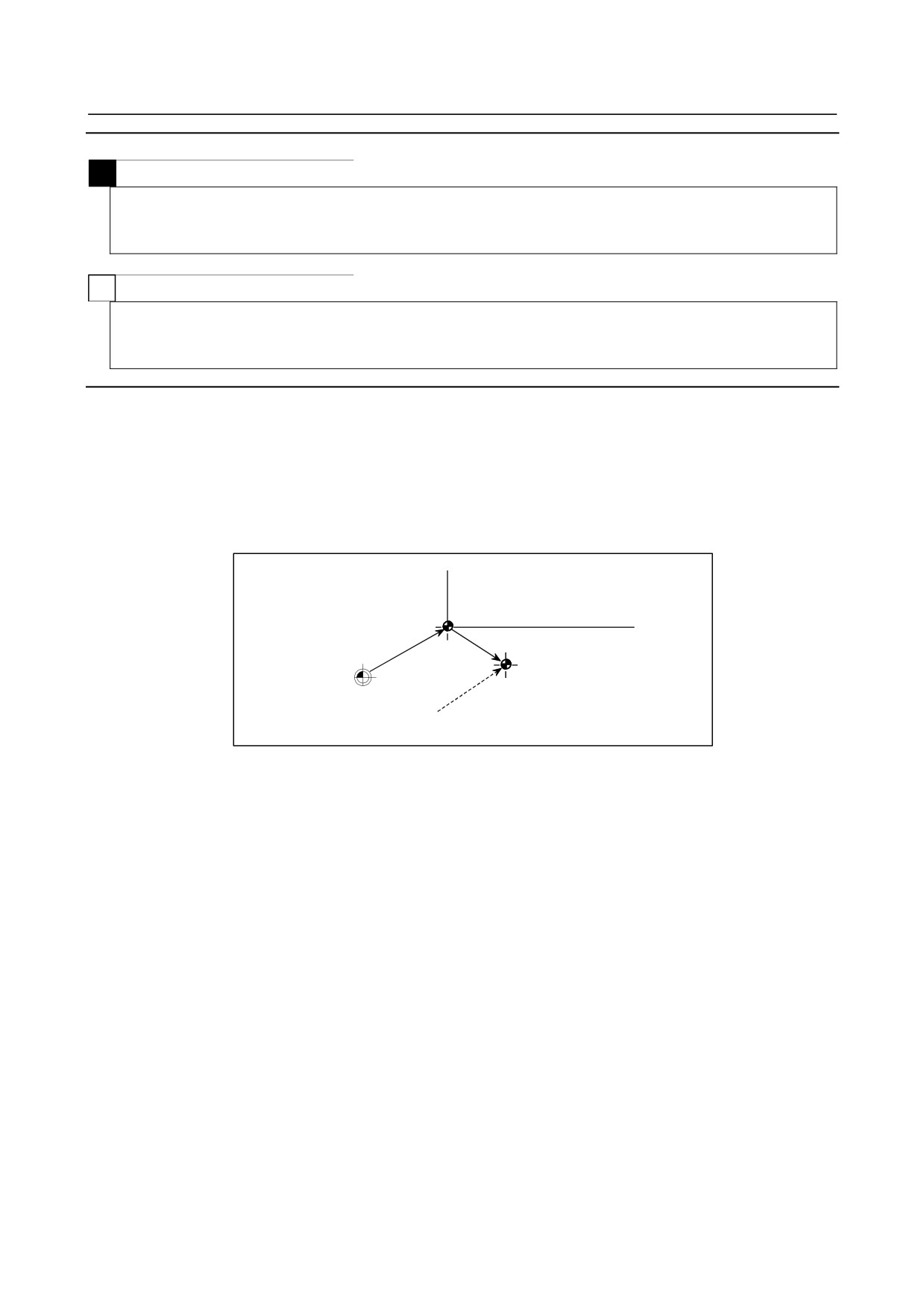
When manual reference position return operation is performed in the reset state, a workpiece coordinate
system is shifted by the workpiece origin offset value from the machine coordinate system zero point.
Suppose that the manual reference position return operation is performed when a workpiece coordinate
system is selected with G54. In this case, a workpiece coordinate system is automatically set which has
its origin displaced from the machine zero point by the G54 workpiece origin offset value; the distance
from the origin of the workpiece coordinate system to the reference position represents the current
position in the workpiece coordinate system.
G54 workpiece coordinate system
Workpiece origin
G54 workpiece
origin offset value
Reference position
Machine zero point
Manual reference position return
If an absolute position detector is provided, the workpiece coordinate system automatically set at
power-up has its origin displaced from the machine zero point by the G54 workpiece origin offset value.
The machine position at the time of power-up is read from the absolute position detector and the current
position in the workpiece coordinate system is set by subtracting the G54 workpiece origin offset value
from this machine position. The workpiece coordinate system set by these operations is shifted from the
machine coordinate system using the commands and operations listed below.
(a) Manual intervention performed when the manual absolute signal is off
(b) Move command executed in the machine lock state
(c) Movement by manual handle interruption
(d) Operation using the mirror image function
(e) Shifting the workpiece coordinate system by setting the local coordinate system or workpiece
coordinate system
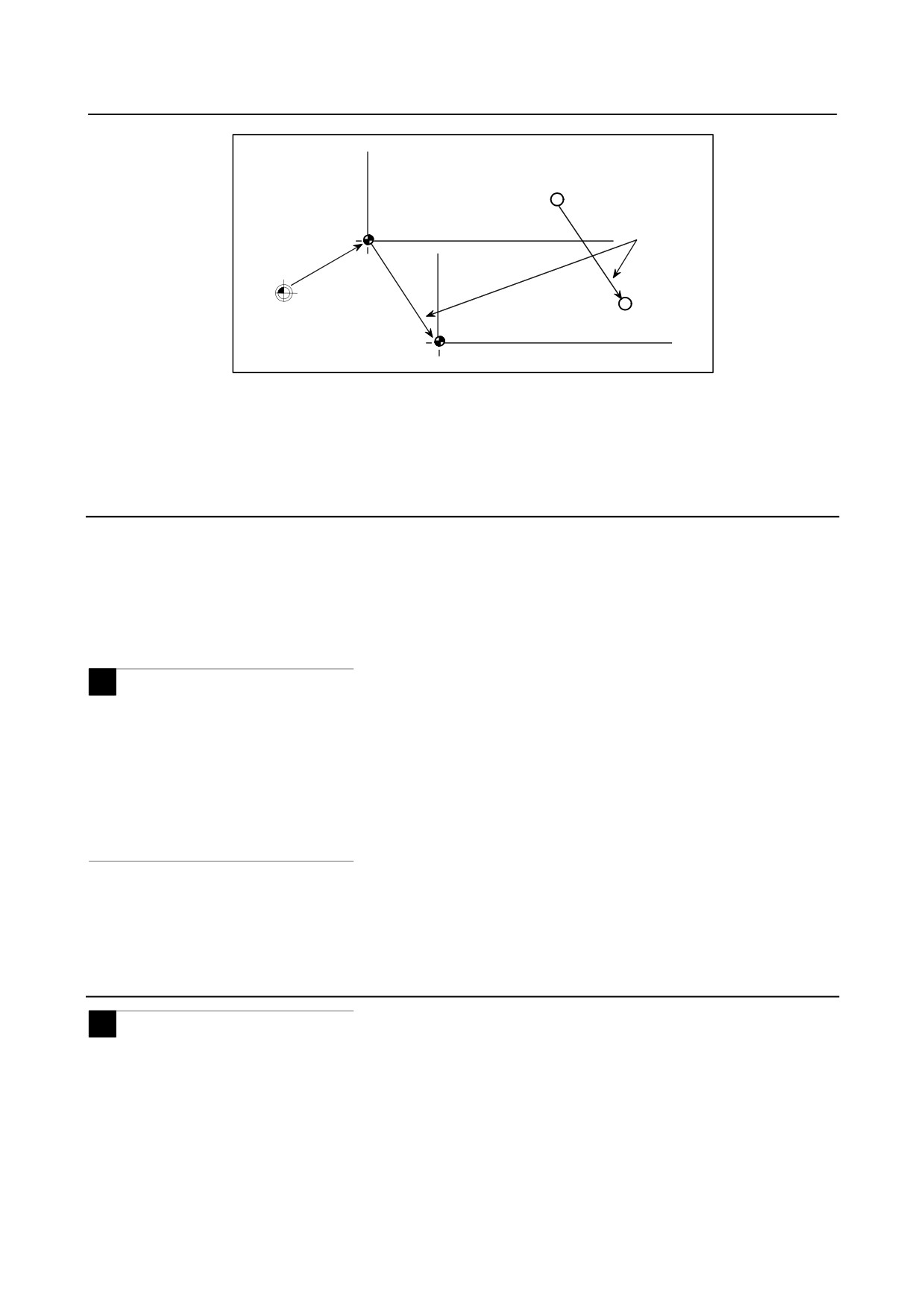
In the case of (a) above, the workpiece coordinate system is shifted by the amount of movement during
manual intervention.
- 82 -
B-64304EN/02
PROGRAMMING
7.COORDINATE SYSTEM
G54 workpiece
Po
coordinate system before
manual intervention
Amount of
movement during
WZo
manual intervention
Workpiece origin
G54 workpiece coordinate
offset value
system after manual
intervention
Pn
Machine zero point
WZn-
In the operation above, a workpiece coordinate system once shifted can be preset using G code (G92.1)
specification or MDI operation to a workpiece coordinate system displaced by a workpiece origin offset
value from the machine zero point.
Bit 3 (PPD) of parameter No. 3104 specifies whether to preset relative coordinates as well as absolute
coordinates.
Limitation
-
Tool radius ⋅ tool nose radius compensation, tool length compensation, tool
offset
When using the workpiece coordinate system preset function, cancel compensation modes: Tool radius ⋅
tool nose radius compensation, tool length compensation, and tool offset. If the function is executed
without canceling these modes, compensation vectors are cancelled.
M
-
Tool length compensation
When using the workpiece coordinate system preset function, cancel tool length compensation. If the
function is executed without canceling these modes, compensation vectors are cancelled.
-
Prohibited modes
Do not use the workpiece coordinate system preset function when the scaling, coordinate system rotation,
or programmable image is set.
-
Program restart
The workpiece coordinate system preset function is not executed during program restart.
7.2.5
Addition of Workpiece Coordinate System Pair (G54.1 or G54)
(M Series)
M
Besides the six workpiece coordinate systems (standard workpiece coordinate systems) selectable with
G54 to G59, 48 additional workpiece coordinate systems (additional workpiece coordinate systems) can
be used.
- 83 -

7.COORDINATE SYSTEM
PROGRAMMING
B-64304EN/02
Format
-
Selecting the additional workpiece coordinate systems
G54.1 Pn ; or G54 Pn ;
Pn : Codes specifying the additional workpiece coordinate systems
n
:
1 to 48
-
Setting the workpiece origin offset value in the additional workpiece
coordinate systems (G10)
G10 L20 Pn IP_ ;
Pn : Codes specifying the workpiece coordinate system for setting the workpiece origin
offset value
n
:
1 to 48
IP_ : Axis addresses and a value set as the workpiece origin offset
Explanation
-
Selecting the additional workpiece coordinate systems
When a P code is specified together with G54.1 (G54), the corresponding coordinate system is selected
from the additional workpiece coordinate systems (1 to 48).
A workpiece coordinate system, once selected, is valid until another workpiece coordinate system is
selected. Standard workpiece coordinate system 1 (selectable with G54) is selected at power-on.
G54.1 P1
Additional workpiece coordinate system 1
G54.1 P2
Additional workpiece coordinate system 2
:
G54.1 P48 Additional workpiece coordinate system 48
As with the standard workpiece coordinate systems, the following operations can be performed for a
workpiece origin offset in an additional workpiece coordinate system:
(1) The workpiece origin offset value setting screen can be used to display and set a workpiece origin
offset value.
(2) The G10 function enables a workpiece origin offset value to be set by programming (refer to
II-7.2.3).
(3) A custom macro allows a workpiece origin offset value to be handled as a system variable.
(4) Workpiece origin offset data can be entered or output as external data.
(5) The PMC window function enables workpiece origin offset data to be read as program command
modal data.
-
Setting the workpiece origin offset value in the additional coordinate systems
(G10)
When a workpiece origin offset value is specified using an absolute value, the specified value is the new
offset value. When it is specified using an incremental value, the specified value is added to the current
offset value to obtain a new offset value.
Limitation
-
Specifying P codes
A P code must be specified after G54.1 (G54). If G54.1 is not followed by a P code in the same block,
additional workpiece coordinate system 1 (G54.1P1) is assumed.
If a value not within the specifiable range is specified in a P code, an alarm PS0030 is issued.
P codes other than workpiece offset numbers cannot be specified in a G54.1 (G54) block.
Example 1) G54.1 G04 P1000 ;
Example 2) G54.1 M98 P48 ;
- 84 -
B-64304EN/02
PROGRAMMING
7.COORDINATE SYSTEM
7.2.6
Automatic Coordinate System Setting
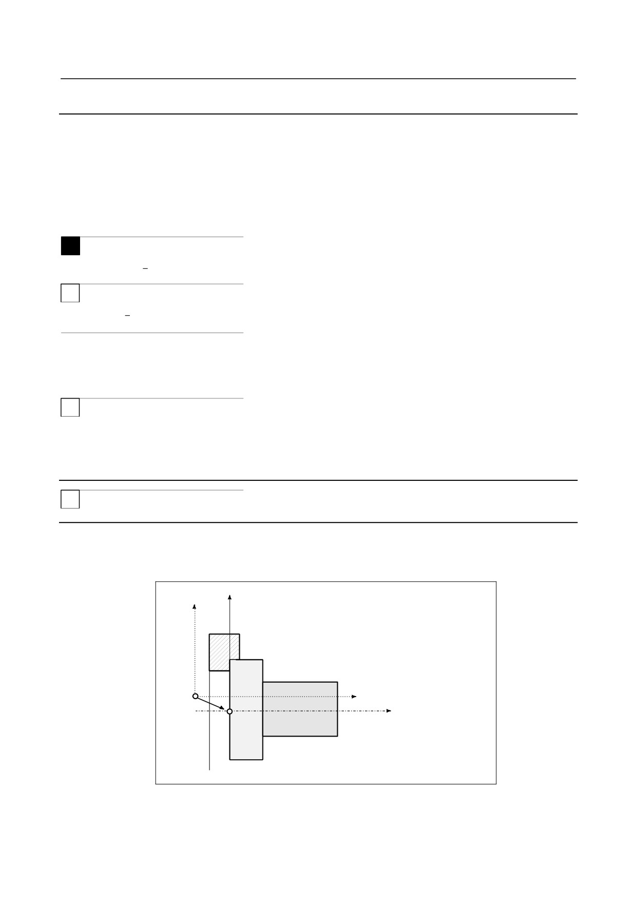
When the workpiece coordinate system is not used (bit 0 (NWZ) of parameter No. 8136 is 1), if bit 0
(ZPR) of automatic coordinate system setting parameter No. 1201 is 1, a manual reference position return
operation determines the coordinates automatically.
Once α, β, and γ are set with parameter No. 1250, a workpiece coordinate system is set upon reference
position return so that the base point on the tool holder or the tip of the basic tool is positioned at X = α,
Y = β, and Z = γ.
This processing occurs as if the following are specified at the reference position:
M
G92 Xα Yβ Zγ ;
T
G50 Xα Zγ ;
When the workpiece coordinate system is used (bit 0 (NWZ) of parameter No. 8136 is 0), regardless of
the setting of bit 0 (ZPR) of parameter No. 1201, a manual reference position return operation establishes
the workpiece coordinate system based on the workpiece origin offset (parameters Nos. 1220 to 1226).
T
When the setting of a workpiece coordinate system shift amount is other than 0, a workpiece coordinate
system shifted by the amount is set.
7.2.7
Workpiece Coordinate System Shift (T Series)
T
Explanation
When the coordinate system actually set by the G50 command or the automatic system setting deviates
from the programmed workpiece system, the set coordinate system can be shifted (see III-3.1).
Set the desired shift amount in the workpiece coordinate system shift memory.
X
x
X-Z : Coordinate system in programming
x-z
: Current set coordinate system with shift amount 0
(coordinate system to be modified by shifting)
O’
z
Shift
Z
O
Set the shift amount from O' to O in the workpiece coordinate system shift memory.
Fig. 7.2.7 (a) Workpiece coordinate system shift
- 85 -
7.COORDINATE SYSTEM
PROGRAMMING
B-64304EN/02
Format
-
Changing the workpiece coordinate system shift amount
G10 P0 IP_;
IP : Settings of an axis address and a workpiece coordinate system shift amount
CAUTION
A single block can contain a combination of X, Y, Z, C, U, V, W, and H (in G
code system A). In this case, if commands are specified for the same axis,
whichever appears later becomes valid.
Limitation
-
Shift amount and coordinate system setting command
Specifying a coordinate system setting command (G50 (for G code system A) or G92 (for G code system
B/C)) invalidates the shift amount that has already been set.
Example)
When G50X100.0Z80.0; is specified, a coordinate system is set so that the current base position of
the tool is at X =100.0 and Z = 80.0, regardless of which value has been set for the workpiece
coordinate system shift amount.
-
Shift amount and coordinate system setting
When the shift amount is already set, if an automatic coordinate system setting is made by a manual
reference position return, the set coordinate system is immediately shifted by the shift amount.
-
Diameter and radius values
The workpiece coordinate system shift amount depends on diameter programming or radius
programming.
Example)
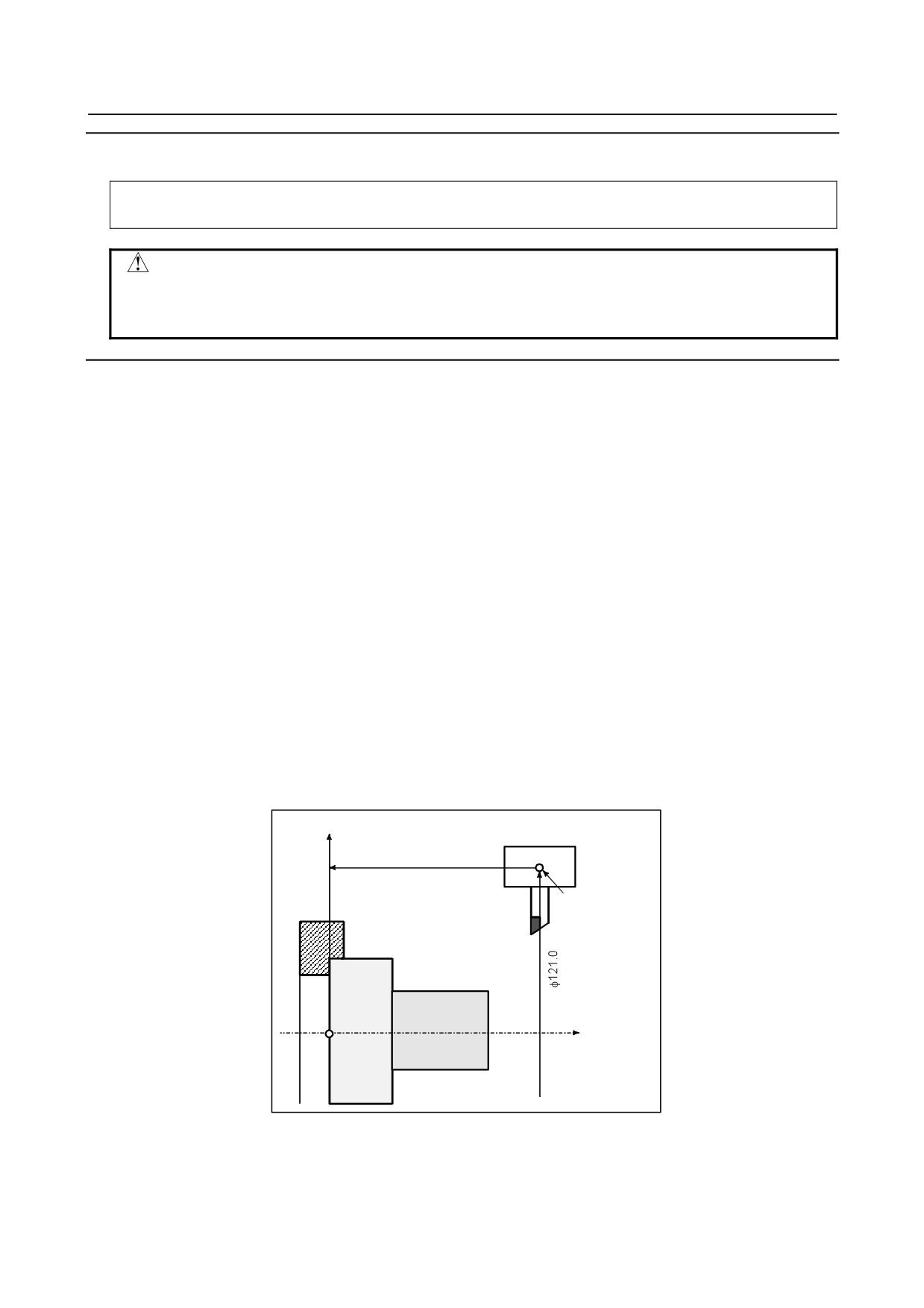
To set the base point indicated by X = Φ120.0 (diameter value) and Z = 70.0 with reference to the
workpiece origin, if the distance to the current base point is indicated by X = Φ121.0 and Z = 69.0,
the shift amount is set as shown below.
X=1.0, Z=-1.0
X
69.0
Start point = base
point
Z
- 86 -
B-64304EN/02
PROGRAMMING
7.COORDINATE SYSTEM
7.3
LOCAL COORDINATE SYSTEM
When a program is created in a workpiece coordinate system, a child workpiece coordinate system can be
set for easier programming. Such a child coordinate system is referred to as a local coordinate system.
Format
G52 IP_; Setting the local coordinate system
:
G52 IP 0 ; Canceling of the local coordinate system
IP_ : Origin of the local coordinate system
Explanation
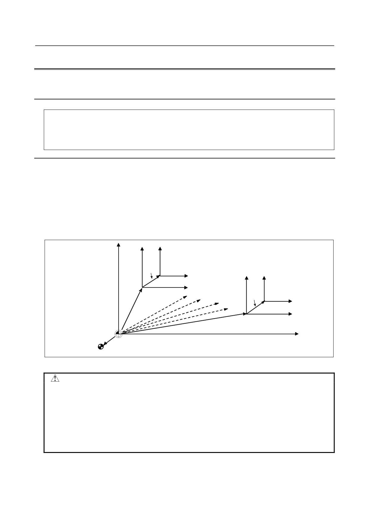
By specifying G52 IP_;, a local coordinate system can be set in all the workpiece coordinate systems
(G54 to G59). The origin of each local coordinate system is set at the position specified by IP_ in the
workpiece coordinate system.
Once a local coordinate system is established, the coordinates in the local coordinate system are used in
an axis shift command. The local coordinate system can be changed by specifying the G52 command
with the origin of a new local coordinate system in the workpiece coordinate system.
To cancel the local coordinate system or specify the coordinate value in the workpiece coordinate system,
match the origin of the local coordinate system with that of the workpiece coordinate system.
IP_
(Local coordinate system)
(G54: Workpiece coordinate system 1)
G55
IP_
(Local coordinate system)
G56
G57
(G59: Workpiece coordinate
G58
system 6)
(Machine coordinate system)
Machine coordinate system zero point
Reference position
Fig. 7.3 (a) Setting the local coordinate system
CAUTION
1 When ZCL (bit 2 of parameter No.1201) is set to 1 and an axis returns to the
reference position by the manual reference position return function, the origin of
the local coordinate system of the axis matches that of the workpiece coordinate
system. The same is true when the following command is issued:
G52 α0 ;
α: Axis which returns to the reference position
2 The local coordinate system setting does not change the workpiece and machine
coordinate systems.
- 87 -
7.COORDINATE SYSTEM
PROGRAMMING
B-64304EN/02
CAUTION
3 Whether the local coordinate system is canceled at reset depends on the
parameter setting. The local coordinate system is canceled when either bit 3
(RLC) of parameter No.1202 is set to 1. The local coordinate system is
canceled regardless of the setting of bit 3 (RLC) of parameter No. 1202 when bit
6 (CLR) of parameter No. 3402 is 0 and bit 7 (WZR) of parameter No. 1201 is 1
or when bit 6 (CLR) of parameter No. 3402 is 1 and bit 6 (C14) of parameter No.
3407 is 0.
4 When a workpiece coordinate system is set with the G92 (G50 for G code
system A in the T series) command, the local coordinate system is canceled.
However, the local coordinate system of an axis for which no coordinate system
is specified in a G92 (G50 for G code system A in the T series) block remains
unchanged.
5 G52 cancels the offset temporarily in tool radius ⋅ tool nose radius compensation.
6 Command a move command immediately after the G52 block in the absolute
mode.
7.4
PLANE SELECTION
Select the planes for circular interpolation, cutter compensation (M series), coordinate system rotation (M
series), and drilling by G-code.
The following table lists G-codes and the planes selected by them.
Explanation
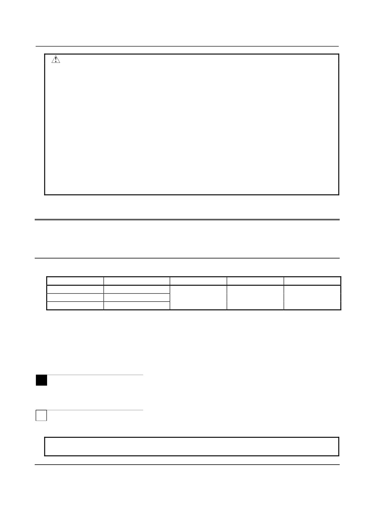
Table 7.4 (a) Plane selected by G code
G code
Selected plane
Xp
Yp
Zp
G17
Xp Yp plane
X-axis or an axis
Y-axis or an axis
Z-axis or an axis
G18
Zp Xp plane
parallel to it
parallel to it
parallel to it
G19
Yp Zp plane
Xp, Yp, Zp are determined by the axis address appeared in the block in which G17, G18 or G19 is
commanded.
When an axis address is omitted in G17, G18 or G19 block, it is assumed that the addresses of basic three
axes are omitted.
Parameter No. 1022 is used to specify that an optional axis be parallel to the each axis of the X-, Y-, and
Z-axes as the basic three axes.
The plane is unchanged in the block in which G17, G18 or G19 is not commanded.
The movement instruction is irrelevant to the plane selection.
M
When the power is turned on or the CNC is reset, G17 (XY plane), G18 (ZX plane), or G19 (YZ plane) is
selected by bits 1 (G18) and 2 (G19) of parameter No. 3402).
T
When the power is turned on, G18 (ZX plane) is selected.
NOTE
U-, V-, and W-axes can be used with G-codes B and C.
Example
Plane selection when the X-axis is parallel with the U-axis.
G17 X_ Y_ ;
XY plane,
- 88 -
B-64304EN/02
PROGRAMMING
7.COORDINATE SYSTEM
G17 U_ Y_ ;
UY plane
G18 X_ Z_ ;
ZX plane
X_Y_ ;
Plane is unchanged (ZX plane)
G17 ;
XY plane
G18 ;
ZX plane
G17 U_ ;
UY plane
G18 Y_ ;
ZX plane, Y axis moves regardless without any relation to the plane.
- 89 -
8.COORDINATE VALUE AND DIMENSION PROGRAMMING
B-64304EN/02
8 COORDINATE VALUE AND DIMENSION
Chapter 8, "COORDINATE VALUE AND DIMENSION", consists of the following sections:
8.1 ABSOLUTE AND INCREMENTAL PROGRAMMING
90
8.2 INCH/METRIC CONVERSION (G20, G21)
92
8.3 DECIMAL POINT PROGRAMMING
95
8.4 DIAMETER AND RADIUS PROGRAMMING
97
8.1
ABSOLUTE AND INCREMENTAL PROGRAMMING
There are two ways to command travels of the tool; the absolute programming, and the incremental
programming. In the absolute programming, coordinate value of the end position is programmed. The
incremental programming is used to program the amount of a tool movement.
M
G90 and G91 are used to programming absolute or incremental programming, respectively.
T
Absolute programming or incremental programming is used depending on the programming used. See
following tables.
G code system
A
B or C
Command method
Address word
G90, G91
Format
M
Absolute programming G90 IP_ ;
Incremental programming G91 IP_ ;
T
-
G code system A
Absolute programming
Incremental programming
X axis move command
X
U
Z axis move command
Z
W
Y axis move command
Y
V
C axis move command
C
H
-
G code system B or C
Absolute programming G90 IP_ ;
Incremental programming G91 IP_ ;
- 90 -
B-64304EN/02
PROGRAMMING
8.COORDINATE VALUE AND DIMENSION
Example
M
G90 X40.0 Y70.0 ;
Absolute programming
G91 X-60.0 Y40.0 ;
Incremental programming
End point
70.0
Y
30.0
Start point
X
40.0
100.0
T
Tool movement from point P to point Q (diameter programming is used for the X-axis)
G code system A
G code system B or C
Absolute programming
X400.0 Z50.0 ;
G90 X400.0 Z50.0 ;
Incremental programming
U200.0 W-400.0 ;
G91 X200.0 Z-400.0 ;
Q
X
(400, 50)
P
(200, 450)
φ400
φ200
Z
50
450
NOTE
1 Absolute programming and incremental programming can be used together in a
block.
In the above example, the following command can be specified : X400.0
W-400.0 ; (in the G code system A)
2 When absolute programming and incremental programming for the same axis
are used at the same time (for example, X and U, or Z and W) in one block in G
code system A, absolute programming or incremental programming, whichever
is specified later, is valid.
3 Incremental programming cannot be used when names of the axes are A and B
during G code system A is selected.
- 91 -
8.COORDINATE VALUE AND DIMENSION PROGRAMMING
B-64304EN/02
8.2
INCH/METRIC CONVERSION (G20, G21)
Either inch or metric input (least input increment) can be selected by G code.
Format
Inch input
Metric input
This G code must be specified in an independent block before setting the coordinate system at the
beginning of the program. After the G code for inch/metric conversion is specified, the unit of input data
is switched to the least inch or metric input increment of increment system (II-2.3). The unit of data input
for degrees remains unchanged. The unit systems for the following values are changed after inch/metric
conversion:
• Feedrate commanded by F code
• Positional command
• Workpiece origin offset value
• Tool compensation value
• Unit of scale for manual pulse generator
• Movement distance in incremental feed
• Some parameters
When the power is turned on, the G code is the same as that held before the power was turned off.
WARNING
G20 and G21 must not be switched during a program.
NOTE
1 When the least input increment and the least command increment systems are
different, the maximum error is half of the least command increment. This error
is not accumulated.
2 The inch and metric input can also be switched using settings (see III-12.3.1).
3 To disable the function of bit 2 (IRF) of parameter No. 14000 or bit 0 (NIM) of
parameter No. 11222, perform inch/metric conversion at a point having a
machine coordinate of 0.
Performing inch/metric conversion in the reference position (parameter No.
1240 is not 0)
Conventionally, inch/metric conversion must be performed at a point having a machine coordinate of 0.
However, setting bit 2 (IRF) of parameter No. 14000 to 1 enables inch/metric conversion to be performed
in the reference position (parameter No. 1240).
If an attempt is made to perform inch/metric conversion when an axis with this function enabled is not in
the reference position, alarm PS5362 is issued to cancel the attempt.
Before trying to perform inch/metric conversion, be sure to set the axis of interest to the reference
position, using the G28 command, for example.
About the axis by which bit 7 (IMAx) of parameter No.14000 is set to 1, even if inch/metric conversion is
performed when the axis is not in the reference position, alarm PS5362 is not generated.
Therefore, be sure to set 1 in IMAx of an unrelated axis to inch/metric conversion such as the rotary axis.
As a result, an unrelated axis to inch/metric conversion need not be performed reference position return
before inch/metric conversion is performed.
- 92 -
B-64304EN/02
PROGRAMMING
8.COORDINATE VALUE AND DIMENSION
In addition, if the workpiece coordinate system has been shifted, using the following commands or
operations, bit 1 (CIM) of parameter No. 11222 can be used to select whether to issue alarm PS1298 or to
clear the offset.
• Manual intervention performed with the manual absolute signal being off
• Move command issued with the machine locked
• Move command issued using a manual handle interrupt
• Mirror image-based operation
• Workpiece coordinate system shift caused by local coordinate system setting (G52) or workpiece
coordinate system setting
Switching conditions
All of the following conditions must be met to perform inch/metric conversion in the reference position.
Failing to satisfy any of the conditions results in alarm PS1298 being issued. For electronic gear box
synchronization, alarm PS1595 is issued.
• Positioning or linear interpolation
• Polar coordinate interpolation cancel mode (T series)
• Polar coordinate command cancel (M series)
• Spindle Speed fluctuation detection off (T series)
• Tool radius ⋅ tool nose radius compensation cancel
• Normal direction control cancel (M series)
• Tool length offset cancel (M series)
• Scaling cancel (M series)
• Programmable mirror image cancel (M series)
• Polygon turning cancel (T series)
• Macro modal call cancel
• Coordinate system rotation mode off (M series)
• Mirror image for double turret or balanced cutting mode cancel (T series)
• Canned cycle cancel
• Electronic gear box synchronization cancel (M series)
• Constant surface speed control cancel
The following setting is necessary to perform inch/metric conversion in the reference position.
• Workpiece coordinate system (parameter NWZ(No.8136#0)=0)
Restrictions
The following operations need to be performed at a point having a machine coordinate of 0.
• Inch/metric conversion based on bit 2 (INI) of setting parameter No. 0
• Inch/metric conversion based on programmable parameter input (G10)
• Inch/metric conversion based on custom macro variable No. 3005
Performing inch/metric conversion in positions other than the reference
position
Setting bit 0 (NIM) of parameter No. 11222 enables inch/metric conversion to be performed even in
positions other than the reference position.
In addition, if the workpiece coordinate system has been shifted, using the following commands or
operations, bit 1 (CIM) of parameter No. 11222 can be used to select whether to issue alarm PS1298 or to
clear the offset.
• Manual intervention performed with the manual absolute signal being off
• Move command issued with the machine locked
• Move command issued using a manual handle interrupt
• Mirror image-based operation
- 93 -
8.COORDINATE VALUE AND DIMENSION PROGRAMMING
B-64304EN/02
• Workpiece coordinate system shift caused by local coordinate system setting (G52) or workpiece
coordinate system setting
If an axis is under any of the following controls, however, no automatic coordinate system conversion
based on this function can be carried out for the axis.
• Axis control by PMC
• Axis synchronous control (for slave axes when the master axis is a PMC axis)
• Spindle control with servo motor
Switching conditions
Performing inch/metric conversion in any position other than the reference position requires satisfying all
of the following conditions. Failing to satisfy any of the conditions results in alarm PS1298 being
issued. For electronic gear box synchronization, alarm PS1595 is issued.
• Positioning or linear interpolation
• Polar coordinate interpolation cancel mode (T series)
• Polar coordinate command cancel (M series)
• Spindle Speed fluctuation detection off (T series)
• Tool radius ⋅ tool nose radius compensation cancel
• Normal direction control cancel (M series)
• Tool length offset cancel (M series)
• Scaling cancel (M series)
• Programmable mirror image cancel (M series)
• Polygon turning cancel (T series)
• Macro modal call cancel
• Coordinate system rotation mode off (M series)
• Mirror image for double turret or balanced cutting mode cancel (T series)
• Canned cycle cancel
• Electronic gear box synchronization cancel (M series)
• Constant surface speed control cancel
The following settings are necessary to perform inch/metric conversion at a point other than the reference
position.
• Workpiece coordinate system (parameter NWZ(No.8136#0)=0)
• Workpiece coordinate system preset
(parameter NWC(No.8136#1)=0)
Restrictions
The following operations need to be performed at a point having a machine coordinate of 0.
• Inch/metric conversion based on bit 2 (INI) of setting parameter No. 0
• Inch/metric conversion based on programmable parameter input (G10)
• Inch/metric conversion based on custom macro variable No. 3005
- 94 -
B-64304EN/02
PROGRAMMING
8.COORDINATE VALUE AND DIMENSION
8.3
DECIMAL POINT PROGRAMMING
Numerical values can be entered with a decimal point. A decimal point can be used when entering a
distance, time, or speed. Decimal points can be specified with the following addresses:
M
X, Y, Z, U, V, W, A, B, C, I, J, K, Q, R, F
T
X, Y, Z, U, V, W, A, B, C, I, J, K, R, F
Explanation
There are two types of decimal point notation: calculator-type notation and standard notation.
When calculator-type decimal notation is used, a value without decimal point is considered to be
specified in millimeters inch, or deg. When standard decimal notation is used, such a value is
considered to be specified in least input increments. Select either calculator-type or standard decimal
notation by using the bit 0 (DPI) of parameter No.3401.Values can be specified both with and without
decimal point in a single program.
Example
Pocket calculator type decimal
Standard type decimal point
Program command
point programming
programming
X1000
1000mm
1mm
Command value without decimal point
Unit :mm
Unit : Least input increment (0.001mm)
X1000.0
1000mm
1000mm
Command value with decimal point
Unit :mm
Unit :mm
CAUTION
When specifying a dimension word for a command G code in a block, be sure to
place the dimension word after the command G code.
- 95 -