FANUC Series 0i-MODEL D, Series 0i Mate-MODEL D. OPERATOR'S MANUAL - page 9
14.CUSTOM MACRO
PROGRAMMING
B-64304EN/02
G66 P9110 Z-20.0 R5.0 F500 ;
G90 X20.0 Y20.0 ;
X50.0 ;
Y50.0 ;
X70.0 Y80.0 ;
G67 ;
M30 ;
-
Macro program (program called)
O9110 ;
#1=#4001 ;
Stores G00/G01.
#3=#4003 ;
Stores G90/G91.
#4=#4109 ;
Stores the cutting feedrate.
#5=#5003 ;
Stores the Z coordinate at the start of drilling.
G00 G90 Z#18 ;
Positioning at position R
G01 Z#26 F#9 ;
Cutting feed to position Z
IF[#4010 EQ 98]GOTO 1 ;
Return to position I
G00 Z#18 ;
Positioning at position R
GOTO 2 ;
N1 G00 Z#5 ;
Positioning at position I
N2 G#1 G#3 F#4 ;
Restores modal information.
M99 ;
Sample program
T
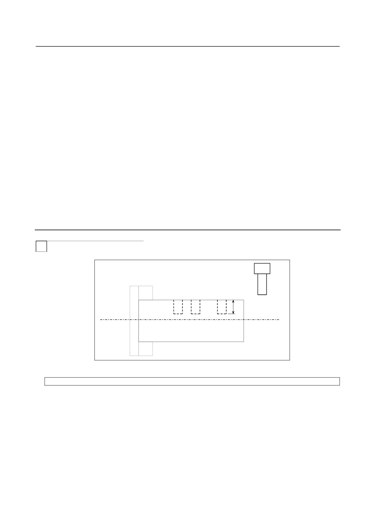
This program makes a groove at a specified position.
U
-
Calling format
G66 P9110 Uu Ff
;
U : Groove depth (incremental programming)
F
: Cutting feed of grooving
-
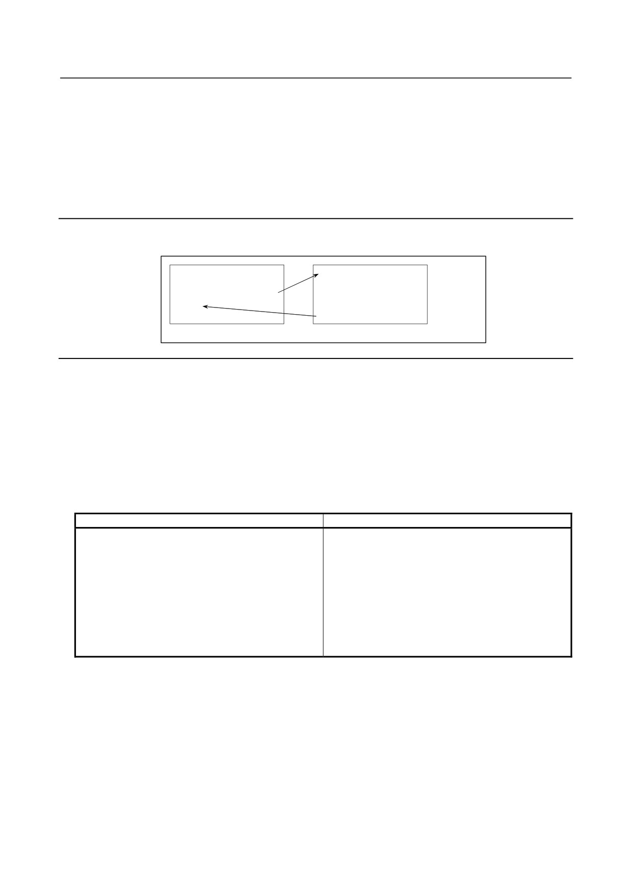
Program that calls a macro program
O0003 ;
G50 X100.0 Z200.0 ;
S1000 M03 ;
G66 P9110 U5.0 F0.5 ;
G00 X60.0 Z80.0 ;
Z50.0 ;
Z30.0 ;
G67 ;
G00 X00.0 Z200.0 M05 ;
- 216 -
B-64304EN/02
PROGRAMMING
14.CUSTOM MACRO
M30 ;
-
Macro program (program called)
O9110 ;
G01 U-#21 F#9 ;
Cuts the workpiece.
G00 U#21 ;
Retracts the tool.
M99 ;
14.7.3 Macro Call Using a G Code
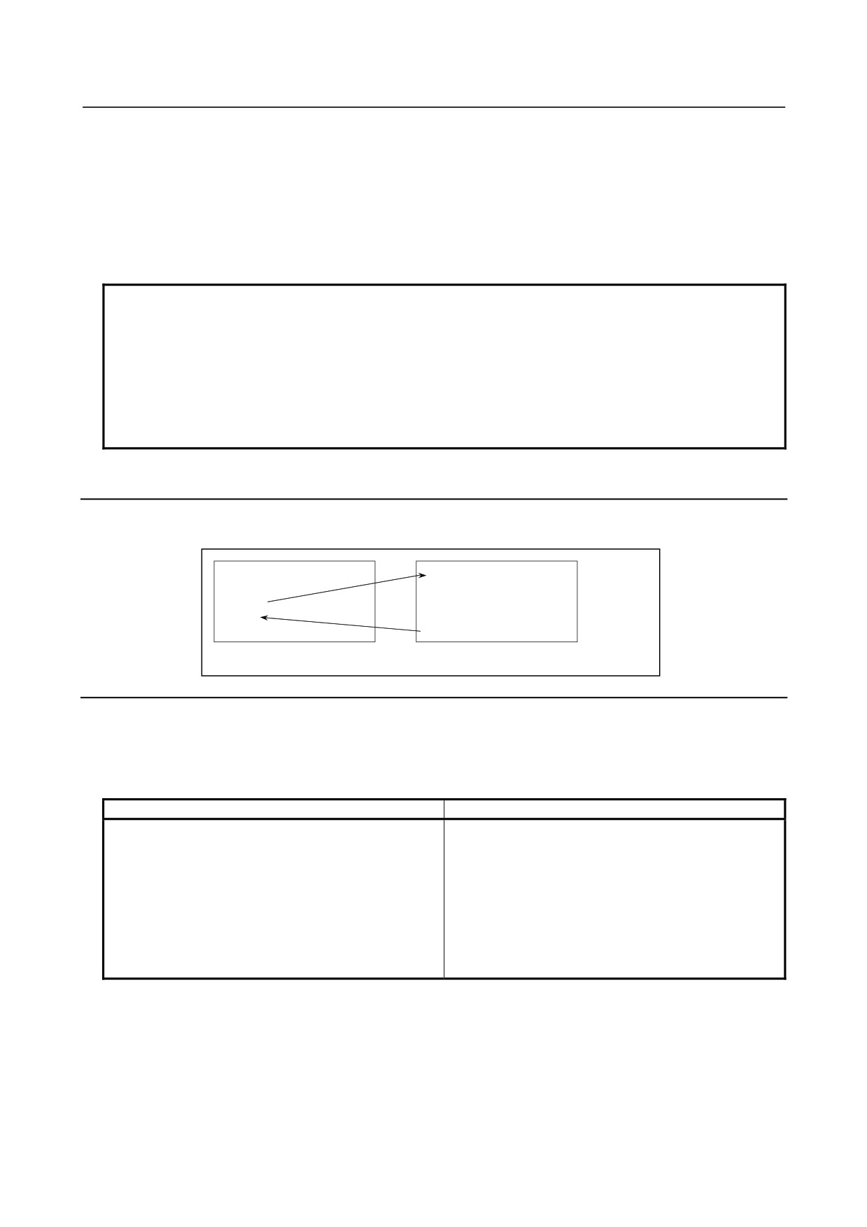
By setting a G code number used to call a macro program in a parameter, the macro program can be
called in the same way as for a simple call (G65).
O0001 ;
O9010 ;
:
:
G81 X10.0 Y20.0 Z-10.0 ;
:
:
:
M30 ;
N9 M99 ;
Parameter No.6050=81
Explanation
By setting a G code number from -9999 to 9999 used to call a custom macro program (O9010 to O9019)
in the corresponding parameter (No.6050 to No.6059), the macro program can be called in the same way
as with G65.
If a negative G code is set, a modal call (equivalent to G66) is made.
For example, when a parameter is set so that macro program O9010 can be called with G81, a
user-specific cycle created using a custom macro can be called without modifying the machining
program.
-
Correspondence between parameter numbers and program numbers
Parameter number
Program number
6050
O9010
6051
O9011
6052
O9012
6053
O9013
6054
O9014
6055
O9015
6056
O9016
6057
O9017
6058
O9018
6059
O9019
-
Repetition
As with a simple call, a number of repetitions from 1 to 99999999 can be specified at address L.
-
Argument specification
As with a simple call, two types of argument specification are available: Argument specification I and
argument specification II. The type of argument specification is determined automatically according to
the addresses used.
- 217 -

14.CUSTOM MACRO
PROGRAMMING
B-64304EN/02
Limitation
-
Nesting of calls using G codes
• To call another program in a program called using a G code, only G65, M98, or G66 can be used
normally.
• When bit 6 (GMP) of parameter No. 6008 is set to 1, a call using an M code, T code, or specific
code can be performed in a program called using a G code.
14.7.4 Macro Call Using a G Code (Specification of Multiple
Definitions)
By setting the starting G code number used to call a macro program, the number of the starting program
to be called, and the number of definitions, macro calls using multiple G codes can be defined.
Explanation
As many custom macros as the number specified in parameter No. 6040 can be called using as many G
codes as the number specified in parameter No. 6040. The numeric value set in parameter No. 6038
indicates the starting G code number and the program number set in parameter No. 6039 indicates the
starting program number. To disable this type of call, set 0 in parameter No. 6040.
If parameter No. 6038 is set to a negative G code, a modal call (equivalent to G66) is made.
The number of repetitions and argument specification are set in the same way as with a macro call using a
G code.
[Example]
Set parameter No. 6038 to 900, parameter No. 6039 to 1000, and parameter No. 6040 to 100.
G900 → O1000
G901 → O1001
G902 → O1002
:
G999 → O1099
Custom macro calls (simple calls) for 100 combinations are defined as shown above. When parameter
No. 6038 is changed to -900, custom macro calls (modal calls) for the same combinations are defined.
NOTE
1 The calls defined by this setting become all invalid in the following cases:
<1> A value outside the valid data range is set in one of the above parameters.
<2> (Setting of parameter No.6039 + Setting of parameter No.6040 - 1) > 9999
2 Simple and modal calls cannot be mixed in the specification.
3 If the G code set in parameter Nos. 6050 to 6059 to call the corresponding
macro program is within the G code range for calling programs using multiple G
codes, the macro program corresponding to the G code set in parameter Nos.
6050 to 6059 is called.
14.7.5 Macro Call Using an M Code
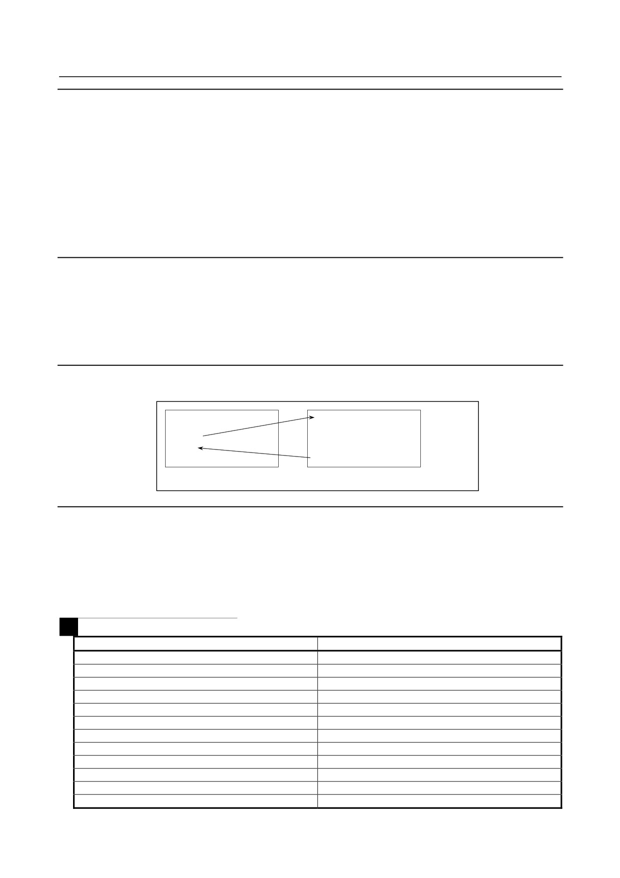
By setting an M code number used to call a macro program in a parameter, the macro program can be
called in the same way as with a simple call (G65).
O0001 ;
O9020 ;
:
:
M50 A1.0 B2.0 ;
:
:
:
M30 ;
M99 ;
Parameter No.6080=50
- 218 -

B-64304EN/02
PROGRAMMING
14.CUSTOM MACRO
Explanation
By setting an M code number from 3 to 99999999 used to call custom macro program O9020 to O9029 in
the corresponding parameter (Nos. 6080 to 6089), the macro program can be called in the same way as
with G65.
-
Correspondence between parameter numbers and program numbers
Parameter number
Corresponding program number
6080
O9020
6081
O9021
6082
O9022
6083
O9023
6084
O9024
6085
O9025
6086
O9026
6087
O9027
6088
O9028
6089
O9029
Example)
When parameter No. 6080 is set to 990, O9020 is called using M990.
-
Repetition
As with a simple call, a number of repetitions from 1 to 99999999 can be specified at address L.
-
Argument specification
As with a simple call, two types of argument specification are available: Argument specification I and
argument specification II. The type of argument specification is determined automatically according to
the addresses used.
Limitation
• An M code used to call a macro program must be specified at the start of a block.
• To call another program in a program called using an M code, only G65, M98, or G66 can be used
normally.
• When bit 6 (GMP) of parameter No. 6008 is set to 1, a call using a G code can be performed in a
program called using an M code.
14.7.6 Macro Call Using an M Code (Specification of Multiple
Definitions)
By setting the starting M code number used to call a macro program, the number of the starting program
to be called, and the number of definitions, macro calls using multiple M codes can be defined.
Explanation
As many custom macros as the number specified in parameter No. 6049 can be called using as many M
codes as the number specified in parameter No. 6049. The numeric value set in parameter No. 6047
indicates the starting M code number and the program number set in parameter No. 6048 indicates the
starting program number. To disable this type of call, set 0 in parameter No. 6049.
The number of repetitions and argument specification are set in the same way as with a macro call using a
M code.
- 219 -
14.CUSTOM MACRO
PROGRAMMING
B-64304EN/02
[Example]
Set parameter No. 6047 to 90000000, parameter No. 6048 to 4000, and parameter No. 6049 to 100.
M90000000 → O4000
M90000001 → O4001
M90000002 → O4002
:
M90000099 → O4099
Custom macro calls (simple calls) for 100 combinations are defined as shown above.
NOTE
1 The calls defined by this setting become all invalid in the following cases:
<1> A value outside the valid data range is set in one of the above parameters.
<2> (Setting of parameter No.6048 + Setting of parameter No.6049 - 1) > 9999
2 If the M code set in parameter Nos. 6080 to 6089 to call the corresponding
macro program is within the M code range for calling programs using multiple M
codes, the macro program corresponding to the M code set in parameter Nos.
6080 to 6089 is called.
14.7.7 Subprogram Call Using an M Code
By setting an M code number used to call a subprogram (macro program) in a parameter, the macro
program can be called in the same way as with a subprogram call (M98).
O0001 ;
O9001 ;
:
:
M03 ;
:
:
:
M30 ;
M99 ;
Parameter No.6071=03
Explanation
By setting an M code number from 3 to 99999999 used to call subprogram O9001 to O9009 in the
corresponding parameters Nos. 6071 to 6079, the subprogram can be called in the same way as with M98.
-
Correspondence between parameter numbers and program numbers
Parameter number
Program number
6071
O9001
6072
O9002
6073
O9003
6074
O9004
6075
O9005
6076
O9006
6077
O9007
6078
O9008
6079
O9009
-
Repetition
As with a simple call, a number of repetitions from 1 to 99999999 can be specified at address L.
-
Argument specification
Argument specification is not allowed.
- 220 -

B-64304EN/02
PROGRAMMING
14.CUSTOM MACRO
-
M code
An M code in a macro program that has been called is treated as an ordinary M code.
Limitation
• To call another program in a program called using an M code, only G65, M98, or G66 can be used
normally.
• When bit 6 (GMP) of parameter No. 6008 is set to 1, a call using a G code can be performed in a
program called using an M code.
14.7.8 Subprogram Call Using an M Code (Specification of Multiple
Definitions)
By setting the starting M code number used to call a subprogram, the number of the starting subprogram
to be called, and the number of definitions, subprogram calls using multiple M codes can be defined.
Explanation
As many sub programs as the number specified in parameter No. 6046 can be called using as many M
codes as the number specified in parameter No. 6046. The numeric value set in parameter No. 6044
indicates the starting M code number and the program number set in parameter No. 6045 indicates the
starting program number. To disable this type of call, set 0 in parameter No. 6046.
[Example]
Set parameter No. 6044 to 80000000, parameter No. 6045 to 3000, and parameter No. 6046 to 100.
M80000000 → O3000
M80000001 → O3001
M80000002 → O3002
:
M80000099 → O3099
Subprogram calls for 100 combinations are defined as shown above.
NOTE
1 The calls defined by this setting become all invalid in the following cases:
<1> A value outside the valid data range is set in one of the above parameters.
<2> (Setting of parameter No.6045 + Setting of parameter No.6046 - 1) > 9999
2 If the M code set in parameter Nos. 6071 to 6079 to call the corresponding
subprogram is within the M code range for calling subprograms using multiple M
codes, the subprogram corresponding to the M code set in parameter Nos. 6071
to 6079 is called.
14.7.9 Subprogram Calls Using a T Code
By enabling subprograms to be called with a T code in a parameter, a subprogram can be called each time
the T code is specified in the machining program.
O0001 ;
O9000 ;
:
:
T23 ;
:
:
:
M30 ;
M99 ;
Bit 5 (TCS) of parameter No. 6001 = 1
- 221 -
14.CUSTOM MACRO
PROGRAMMING
B-64304EN/02
Explanation
-
Call
By setting bit 5 (TCS) of parameter No. 6001 to 1, subprogram O9000 can be called each time a T code is
specified in a machining program. A T code specified in a machining program is assigned to common
variable #149.
-
Repetition
As with a simple call, a number of repetitions from 1 to 99999999 can be specified at address L.
-
Argument specification
Argument specification is not allowed.
Limitation
• To call another program in a program called using a T code, only G65, M98, or G66 can be used
normally.
• When bit 6 (GMP) of parameter No. 6008 is set to 1, a call using a G code can be performed in a
program called using a T code.
14.7.10 Subprogram Call Using a Specific Address
By enabling subprograms to be called with a specific address in a parameter, a subprogram can be called
each time the specific address is specified in the machining program.
O0001 ;
O9004 ;(#146=100.)
:
:
B100. ;
:
:
:
M30 ;
M99 ;
Parameter No.6090=66(B)
Explanation
-
Call
By setting the code (ASCII code converted to decimal) corresponding to a specific address in parameter
No. 6090 or No. 6091, the custom macro program, O9004 or O9005, corresponding to each parameter can
be called when the specific address is specified in a machining program. The code value corresponding
to a specific address specified in a machining program is assigned to the common variables (#146, #147).
The table below indicates the addresses that can be set.
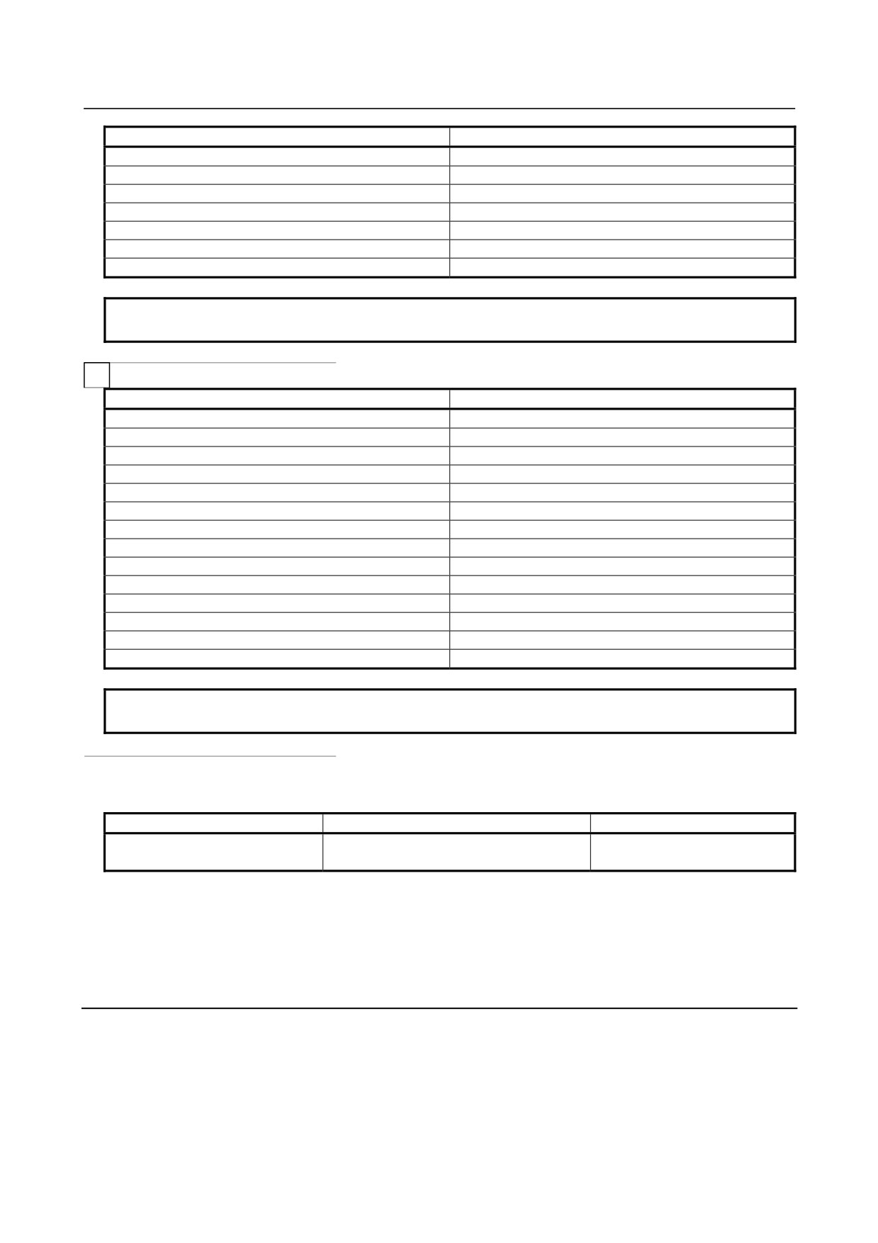
M
Address
Parameter setting
A
65
B
66
D
68
F
70
H
72
I
73
J
74
K
75
L
76
M
77
P
80
Q
81
- 222 -
B-64304EN/02
PROGRAMMING
14.CUSTOM MACRO
Address
Parameter setting
R
82
S
83
T
84
V
86
X
88
Y
89
Z
90
NOTE
When address L is set, the number of repetitions cannot be set.
T
Address
Parameter setting
A
65
B
66
F
70
H
72
I
73
J
74
K
75
L
76
M
77
P
80
Q
81
R
82
S
83
T
84
NOTE
When address L is set, the number of repetitions cannot be set.
-
Correspondence between parameter numbers and program numbers and
between the parameter numbers and common variables
Parameter number
Program number
Common variable
6090
O9004
#146
6091
O9005
#147
-
Repetition
As with a simple call, a number of repetitions from 1 to 99999999 can be specified at address L.
-
Argument specification
Argument specification is not allowed.
Limitation
• To call another program in a program called using a specific address, only G65, M98, or G66 can be
used normally.
• When bit 6 (GMP) of parameter No. 6008 is set to 1, a call using a G code can be performed in a
program called using a specific address.
- 223 -

14.CUSTOM MACRO
PROGRAMMING
B-64304EN/02
Sample program
By using the subprogram call function that uses M codes, the cumulative usage time of each tool is
measured.
Conditions
• The cumulative usage time of each of tools T01 to T05 is measured.
No measurement is made for tools with numbers greater than T05.
• The following variables are used to store the tool numbers and measured times:
#501
Cumulative usage time of tool number 1
#502
Cumulative usage time of tool number 2
#503
Cumulative usage time of tool number 3
#504
Cumulative usage time of tool number 4
#505
Cumulative usage time of tool number 5
• Usage time starts being counted when the M03 command is specified and stops when M05 is
specified. System variable #3002 is used to measure the time during which the cycle start lamp is
on. The time during which the machine is stopped by feed hold and single block stop operation is
not counted, but the time used to change tools and pallets is included.
Operation check
-
Parameter setting
Set 3 in parameter No.6071, and set 5 in parameter No.6072.
-
Variable value setting
Set 0 in variables #501 to #505.
-
Program that calls a macro program
O0001 ;
T01 M06 ;
M03 ;
:
M05 ;
Changes #501.
T02 M06 ;
M03 ;
:
M05 ;
Changes #502.
T03 M06 ;
M03 ;
:
M05 ;
Changes #503.
T04 M06 ;
M03 ;
:
M05 ;
Changes #504.
T05 M06 ;
M03 ;
:
M05 ;
Changes #505.
M30 ;
-
Macro program (program called)
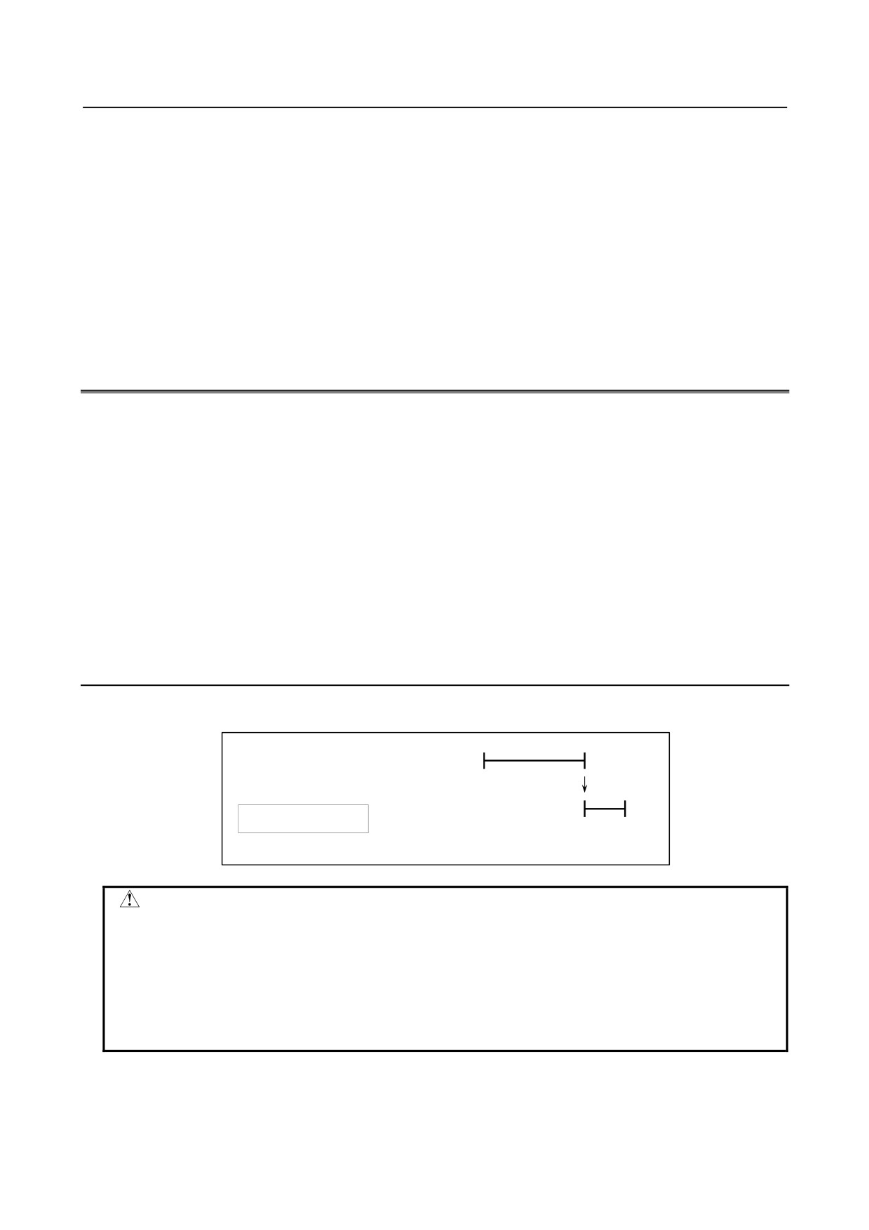
O9001(M03) ;
Macro to start counting
M01 ;
IF[#4120 EQ 0]GOTO 9 ;
No tool specified
IF[#4120 GT 5]GOTO 9 ;
Out-of-range tool number
- 224 -
B-64304EN/02
PROGRAMMING
14.CUSTOM MACRO
#3002=0 ;
Clears the timer.
N9 M03 ;
Rotates the spindle in the
M99 ;
forward direction.
O9002(M05) ;
Macro to end counting
M01 ;
IF[#4120 EQ 0]GOTO 9 ;
No tool specified
IF[#4120 GT 5]GOTO 9 ;
Out-of-range tool number
#[500+#4120]=#3002+#[500+#4120] ;
Calculates cumulative time.
N9 M05 ;
Stops the spindle.
M99 ;
14.8 PROCESSING MACRO STATEMENTS
For smooth machining, the CNC prereads the NC statement to be performed next. This operation is
referred to as buffering. For example, many NC statements are buffered during look-ahead by AI
advanced preview control (M series) / AI contour control (M series).
In the cutter compensation mode (G41 or G42) for M series, the CNC prereads the NC statements at least
three blocks ahead to find intersections even if look-ahead by AI contour control and so forth is not
applied.
Macro statements for arithmetic expressions and conditional branches are processed as soon as they are
read into the buffer. Therefore, the timing of the macro statement execution is not always the specified
order.
At the blocks containing M00, M01, M02 or M30, blocks containing M-codes for which buffering is
suppressed by setting parameters Nos. 3411 to 3420 and No.3421 to 3432, and blocks containing
prevention buffering G codes such as G31 or G53, the CNC stops to preread the NC statement after that.
Then, the stop of the macro statement execution is guaranteed until such M codes or G codes complete its
execution.
Explanation
-
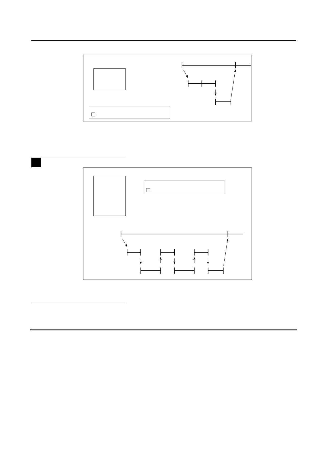
When the next block is not buffered (M codes that are not buffered, G31, etc.)
> N1 G31 X100.0 ;
N1
NC statement
N2 #100=1
:
execution
N2
Macro statement execution
> :Block being executed
Buffer
CAUTION
In case that you need to execute the macro statement after completing the block
just before the macro statement, specify M code or G code that is not buffered
just before the macro statement. Specially, in case of reading/writing the system
variables to control signals, coordinates, offset value, etc., it may different system
variable data by the timing of the NC statement execution. To avoid this
phenomenon, specify such M codes or G codes before the macro statement, if
necessary.
- 225 -
14.CUSTOM MACRO
PROGRAMMING
B-64304EN/02
-
Buffering the next block in other than cutter compensation mode (G41, G42)
> N1 X100.0 ;
N1
N4
NC statement
execution
N2 #1=100 ;
N3 #2=200 ;
N2
N3
Macro statement
N4 Y200.0 ;
execution
Buffer
N4
> : Block being executed
: Block read into the buffer
When N1 is being executed, the next NC statement (N4) is read into the buffer.
The macro statements
(N2, N3) between N1 and N4 are processed during execution of N1.
-
In cutter compensation mode (G41, G42)
M
> N1 G01 G41 X100.0 F100 Dd ;
N2 #1=100 ;
> : Block being executed
N3 Y100.0 ;
: Blocks read into the buffer
N4 #2=200 ;
N5 Y150.0 ;
N6 #3=300 ;
N7 X200.0 ;
:
N1
N3
NC statement
execution
N2
N4
N6
Macro statement
execution
N3
N5
N7
Buffer
When N1 is being executed, the NC statements in the next three blocks (up to N7) are read into the buffer.
The macro statements (N1, N4, N6) between N1 and N7 are processed during execution of N1.
14.9 REGISTERING CUSTOM MACRO PROGRAMS
Custom macro programs are similar to subprograms. They can be registered and edited in the same way
as subprograms. The storage capacity is determined by the total length of tape used to store both custom
macros and subprograms.
- 226 -

B-64304EN/02
PROGRAMMING
14.CUSTOM MACRO
14.10 CODES AND RESERVED WORDS USED IN CUSTOM
MACROS
In addition to the codes used in ordinary programs, the following codes are used in custom macro
programs.
Explanation
-
Codes
(1)
When the ISO code is used or when bit 4 (ISO) of parameter No. 6008 is set to 0
(The codes are represented in hexadecimal.)
Meaning
Code
0AAh
=
0BDh
#
0A3h
[
0DBh
]
0DDh
?
03Fh
@
0C0h
&
0A6h
_
05Fh
O
0CFh
(2)
When the EIA code is used or when the ISO code is used with bit 4 (ISO) of parameter No. 6008 set
to 1
Meaning
Code
Code set in parameter No. 6010
=
Code set in parameter No. 6011
#
Code set in parameter No. 6012
[
Code set in parameter No. 6013
]
Code set in parameter No. 6014
?
Code set in parameter No. 6015
@
Code set in parameter No. 6016
&
Code set in parameter No. 6017
_
Code set in parameter No. 6018
For O, the same code as for O indicating a program number is used. Set a hole pattern for each of *, =, #,
[, ], ?, @, &, and _ in the ISO or EIA code in the corresponding parameter (Nos. 6010 to 6018).
The code 00h cannot be used. The code indicating an alphabetic character can be used for the code
indicating a character listed above, but the code can be no longer used to indicate the original character.
-
Reserved words
The following reserved words are used in custom macros:
AND, OR, XOR, MOD, EQ, NE, GT, LT, GE, LE, SIN, COS, TAN, ASIN, ACOS, ATAN, ATN, SQRT,
SQR, ABS, BIN, BCD, ROUND, RND, FIX, FUP, LN, EXP, POW, ADP, IF, GOTO, WHILE, DO,
END, BPRNT, DPRNT, POPEN, PCLOS, SETVN
System variable (constant) names and registered common variable names are also used as reserved words.
- 227 -
14.CUSTOM MACRO
PROGRAMMING
B-64304EN/02
14.11 EXTERNAL OUTPUT COMMANDS
In addition to the standard custom macro commands, the following macro commands are available.
They are referred to as external output commands.
• BPRNT
• DPRNT
• POPEN
• PCLOS
These commands are provided to output variable values and characters through the reader/puncher
interface.
Explanation
Specify these commands in the following order:
Open command: POPEN
Before specifying a sequence of data output commands, specify this command to establish a
connection to an external input/output device.
Data output command: BPRNT or DPRNT
Specify necessary data output.
Close command: PCLOS
When all data output commands have completed, specify PCLOS to release a connection to an
external input/output device.
-
Open command POPEN
The POPEN command establishes a connection to an external input/output device. It must be specified
before a sequence of data output commands. The CNC outputs a DC2 control code.
-
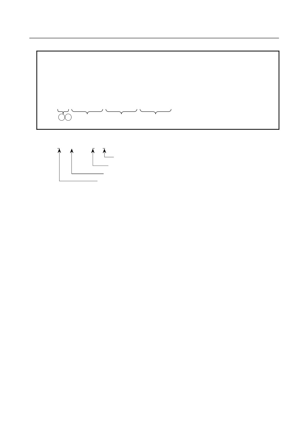
Data output command BPRNT
The BPRNT command outputs characters and variable values in binary.
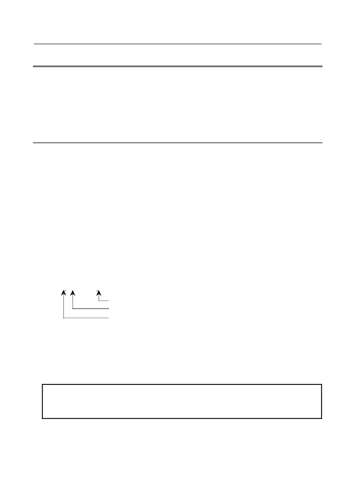
BPRNT [ a
#b
[c] … ]
Number of significant decimal places
Variable
Character
(i)
Specified characters are converted to the codes according to the setting data (ISO) that is output at
that time.
Specifiable characters are as follows:
• Letters (A to Z)
• Numbers
• Special characters (*, /, +, -, ?, @, &, _)
NOTE
1 An asterisk (*) is output by a space code.
2 When using ?, @, &, and/or _, use the ISO code as the punch code (setting data
(ISO) = 1).
(ii) All variables are stored with a decimal point. Specify a variable followed by the number of
significant decimal places enclosed in brackets. A variable value is treated as 2-word (32-bit) data,
including the decimal digits. It is output as binary data starting from the highest byte.
(iii) When specified data has been output, an EOB code is output according to the setting code (ISO).
(iv)
<Null> variables are regarded as 0.
- 228 -
B-64304EN/02
PROGRAMMING
14.CUSTOM MACRO
Example
BPRNT [ C** X#100 [3] Y#101 [3] M#10 [0] ]
Variable value
#100=0.40956
#101=-1638.4
#10=12.34
are output as follows:
C3 A0 A0 D8 00 00 01 9A 59 FF E7 00 00 4D 00 00 00 0C 0A
↓
↓
C sp sp X0000019A YFFE70000 M0000000C
LF
( * * )
(410)
(-1638400)
(12)
( ; )
-
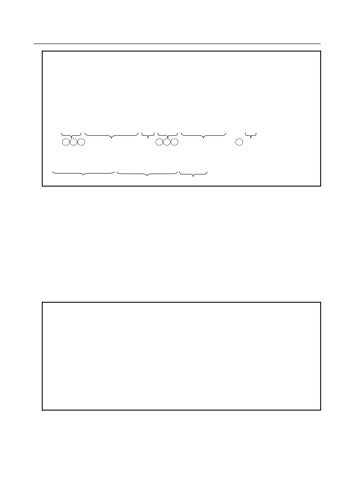
Data output command DPRNT
DPRNT
[ a
#b
[c
d] … ]
Number of significant decimal places
Number of significant digits in the integer part
Variable
Character
The DPRNT command outputs characters and each digit in the value of a variable according to the code
set in the settings (ISO).
(i)
For an explanation of the DPRNT command, see Items (i), (iii), and (iv) for the BPRNT command.
(ii) When outputting a variable, specify # followed by the variable number, then specify the number of
digits in the integer part and the number of decimal places enclosed in brackets.
For the value of a variable, as many codes as the specified number of digits are output according to
the settings one by one, starting with the highest digit. The decimal point is also output using the
set code.
Each variable must be a numeric value consisting of up to nine digits. When high-order digits are
zeros, these zeros are not output if bit 1 (PRT) of parameter No. 6001 is 1. If parameter PRT is 0, a
space code is output each time a zero is encountered.
When the number of decimal places is not zero, digits in the decimal part are always output. If the
number of decimal places is zero, no decimal point is output.
When bit 1 (PRT) of parameter No. 6001 is 0, a space code is output to indicate a positive number
instead of +; if parameter PRT is 1, no code is output.
- 229 -
14.CUSTOM MACRO
PROGRAMMING
B-64304EN/02
Example
DPRNT [ X#2 [53] Y#5 [53] T#30 [20] ]
Variable value
#2=128.47398
#5=-91.2
#30=123.456
are output as follows:
(1) Parameter PRT (No.6001#1) = 0
D8 A0 A0 A0 B1 B2 B8 2E B4 B7 B4 59 2D A0 A0 A0 39 B1 2E B2 30 30 D4 A0 B2 33 0A
↓
↓
↓
↓
X sp sp sp
128.474
Y- sp sp sp
91.200
T
sp
023 LF
(2) Parameter PRT (No.6001#1) = 1
D8 B1 B2 B8 2E B4 B7 B4 59 2D 39 B1 2E B2 30 30 D4 A0 B2 33 0A
↓
X128.474
Y-91.200
T023 LF
-
Close command PCLOS
The PCLOS command releases a connection to an external input/output device. Specify this command
when all data output commands have terminated. DC4 control code is output from the CNC.
-
Required setting
Specify the specification number of an input/output device to be used for the I/O device specification
number.
According to the above settings, set data items (such as the baud rate) for the reader/puncher interface.
Do not specify the FANUC Cassette or FLOPPY unit as an external output device.
When specifying a DPRNT command to output data, specify whether leading zeros are output as spaces
(by setting bit 1 (PRT) of parameter No. 6001 to 1 or 0).
To indicate the end of a line of data in ISO code, specify whether to use only an LF (bit 4 (CRO) of
parameter 6001 is 0) or an LF and CR bit 4 (CRO) of parameter 6001 is 1).
NOTE
1 It is not necessary to always specify the open command (POPEN), data output
command (BPRNT, DPRNT), and close command (PCLOS) together. Once an
open command is specified at the beginning of a program, it does not need to be
specified again except after a close command was specified.
2 Be sure to specify open commands and close commands in pairs. Specify the
close command at the end of the program. However, do not specify a close
command if no open command has been specified.
3 When a reset operation is performed while commands are being output by a
data output command, output is stopped and subsequent data is erased. If a
reset is caused by M30 or other commands at the end of a program that is
outputting data, wait until all data is output by, for example, specifying the close
command at the end of the program and then execute M30 or other commands.
- 230 -
B-64304EN/02
PROGRAMMING
14.CUSTOM MACRO
14.12 RESTRICTIONS
-
Single block
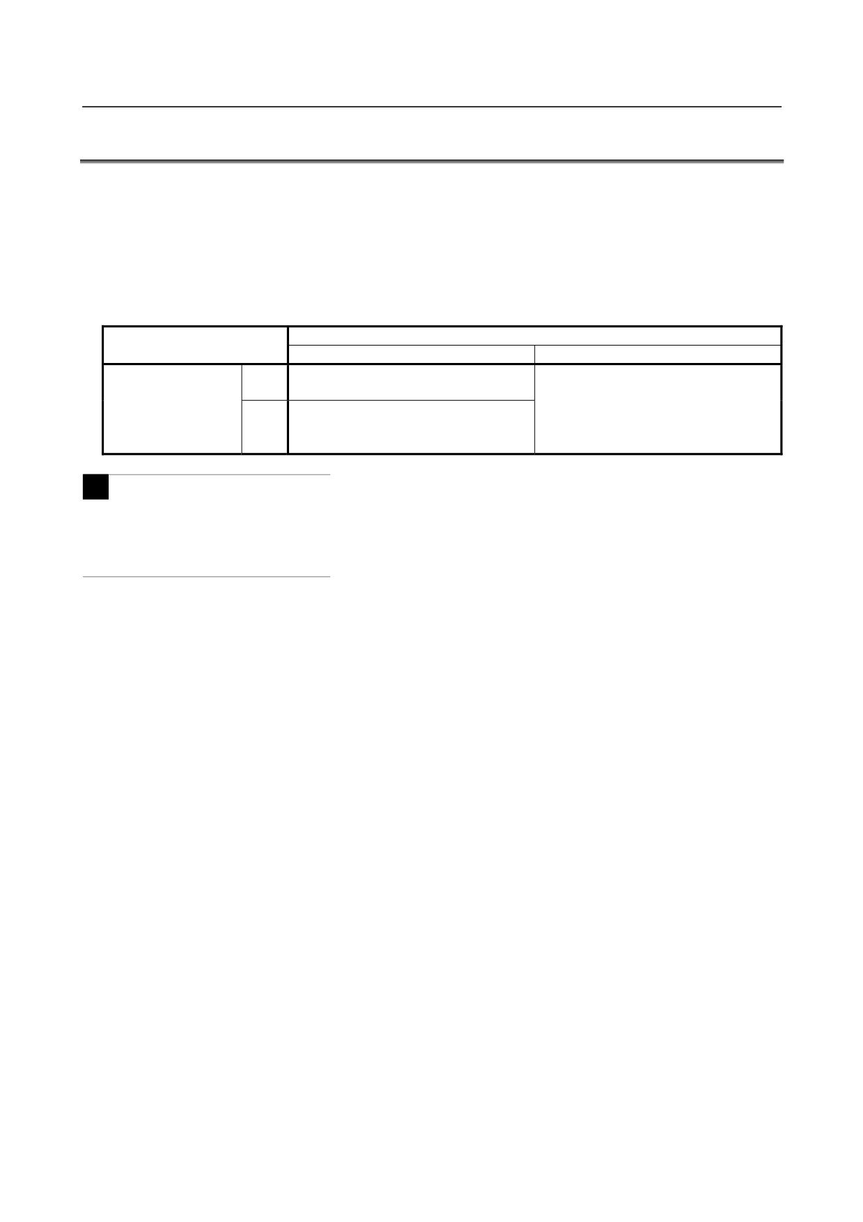
Even while a macro program is being executed, blocks can be stopped in the single block mode.
A block containing a macro call command (G65, G66, Ggg, Mmm, or G67) does not stop even when the
single block mode is on.
Whether blocks containing arithmetic and logic operation commands and control commands are stopped
depends on the settings of bits 5 (SBM) and 7 (SBV) of parameter No. 6000 as shown in the following
table.
Bit 5 (SBM) of parameter No. 6000
0
1
Not stopped when the single block mode
Can be stopped in the single block mode.
0
is on.
(Variable #3003 cannot be used to
Bit 7 (SBV) of
Can be stopped in the single bock mode.
disable single block stop. Single block
parameter No. 6000
1
(Variable #3003 can be used to enable or
stop is always enabled.)
disable single block stop.)
M
Note that when a single block stop occurs at a macro statement in cutter compensation mode, the
statement is assumed to be a block that does not involve movement, and proper compensation cannot be
performed in some cases.
(Strictly speaking, the block is regarded as specifying a movement with a
travel distance 0.)
-
Optional block skip
A / appearing in the middle of an <expression> (enclosed in brackets [
] on the right-hand side of an
arithmetic expression) is regarded as a division operator; it is not regarded as the specifier for an optional
block skip code.
-
Operation in EDIT mode
By setting bit 0 (NE8) of parameter No.3202 and bit 4 (NE9) of parameter No.3202 to 1, deletion and
editing are disabled for custom macro programs and subprograms with program numbers 8000 to 8999
and 9000 to 9999. This prevents registered custom macro programs and subprograms from being
destroyed by accident. When the entire memory is cleared, the contents of memory such as custom
macro programs are deleted.
-
Reset
With a reset operation, local variables and common variables #100 to #199 are cleared to null values.
However, bit 6 (CCV) of parameter No. 6001 can be set to prevent variables #100 to #199 from being
cleared.
A reset operation clears any called states of custom macro programs and subprograms, and any DO states,
and returns control to the main program.
-
Display of the PROGRAM RESTART
As with M98, the M and T codes used for subprogram calls are not displayed.
-
Feed hold
When a feed hold is enabled during execution of a macro statement, the machine stops after execution of
the macro statement. The machine also stops when a reset or alarm occurs.
-
DNC operation
The control commands (such as GOTO and WHILE-DO) cannot be executed during DNC operation.
- 231 -
14.CUSTOM MACRO
PROGRAMMING
B-64304EN/02
However, this restriction is removed when a program registered in program memory is called during DNC
operation.
-
Constant values that can be used in <expression>
+0.00000000001 to +999999999999
-999999999999 to -0.00000000001
The number of significant digits is 12 (decimal).
If this range is exceeded, an alarm PS0012 occurs.
14.13 INTERRUPTION TYPE CUSTOM MACRO
When a program is being executed, another program can be called by inputting an interrupt signal (UINT)
from the machine.
This function is referred to as an interruption type custom macro function. Program an interrupt
command in the following format:
Format
M96Pxxxx ; Enables custom macro interrupt
M97 ;
Disables custom macro interrupt
Explanation
Use of the interruption type custom macro function allows the user to call a program during execution of
an arbitrary block of another program. This allows programs to be operated to match situations which
vary from time to time.
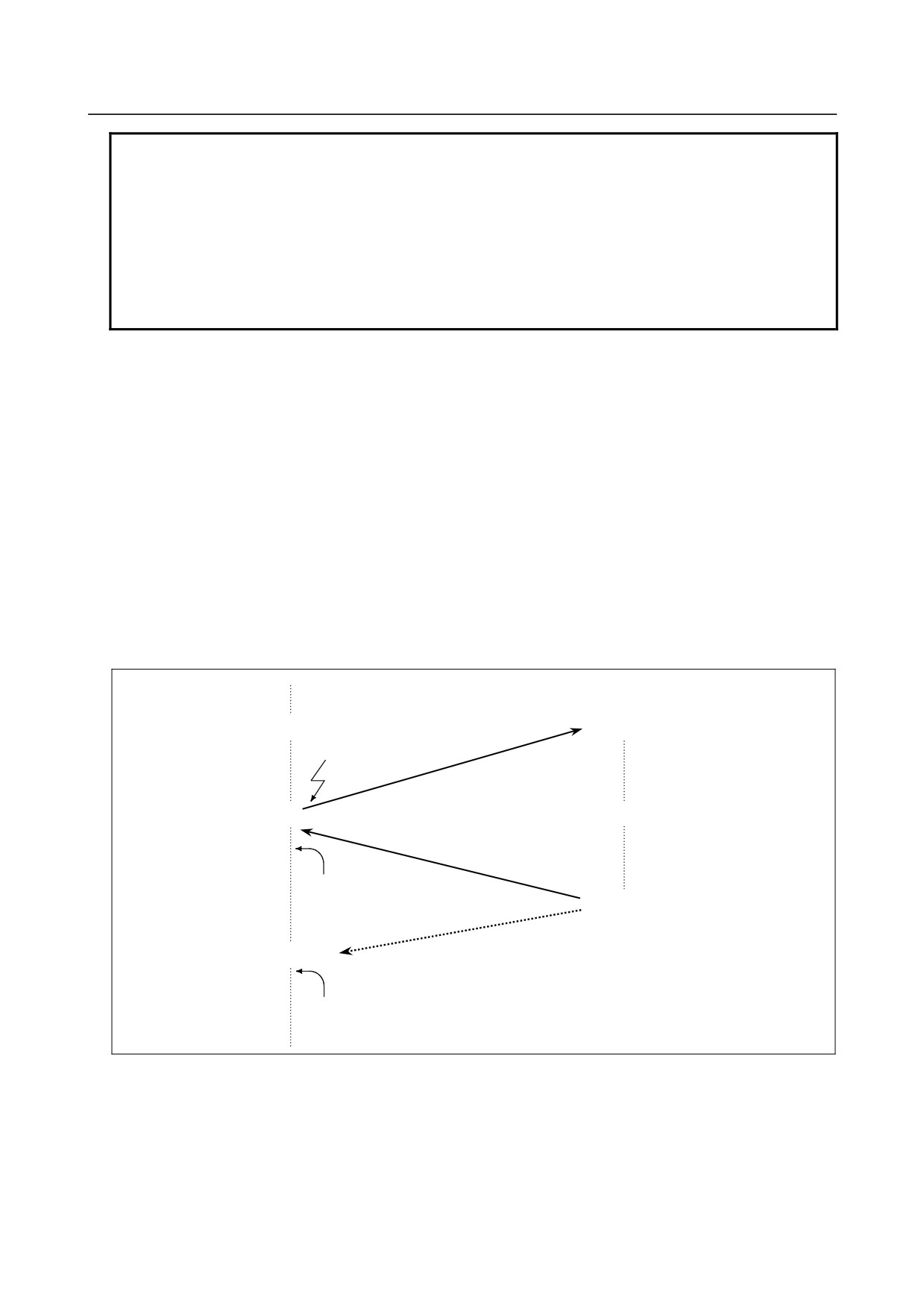
(1) When a tool abnormality is detected, processing to handle the abnormality is started by an external
signal.
(2) A sequence of machining operations is interrupted by another machining operation without the
cancellation of the current operation.
(3) At regular intervals, information on current machining is read.
Listed above are examples like adaptive control applications of the interruption type custom macro
function.
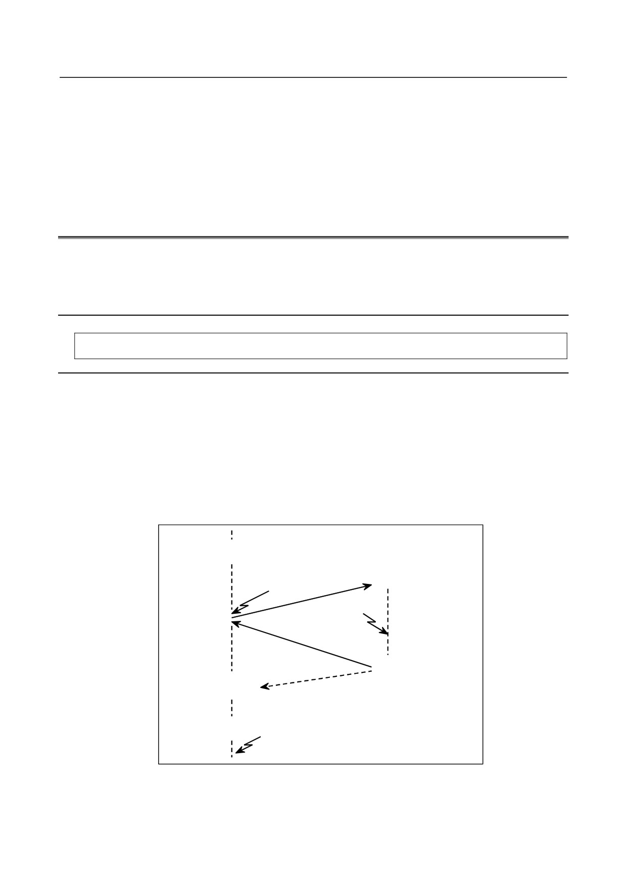
M96 Pxxxx;
Interrupt signal
(UINT)
Oxxxx;
Interrupt signal
(UINT) **
M99 (Pyyyy);
Nyyyy;
M97;
Interrupt signal
(UINT) *
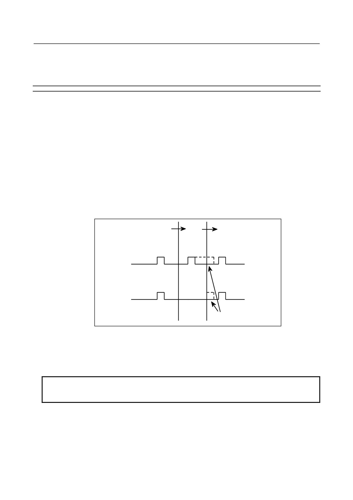
Fig 14.13 (a) Interruption type custom macro function
When M96Pxxxx is specified in a program, subsequent program operation can be interrupted by an
interrupt signal (UINT) input to execute the program specified by Pxxxx. When the interrupt signal
- 232 -
B-64304EN/02
PROGRAMMING
14.CUSTOM MACRO
((UINT)** and (UINT)* in Fig 14.13 (a)) is input during execution of the interrupt program or after M97,
it is ignored.
14.13.1 Specification Method
Explanation
-
Interrupt conditions
A custom macro interrupt is available only during program execution. It is enabled under the following
conditions
• When memory operation, DNC operation, or MDI operation is selected
• When STL (start lamp) is on
• When a custom macro interrupt is not currently being processed
A custom macro interrupt cannot be performed during manual operation.
-
Specification
Generally, the custom macro interrupt function is used by specifying M96 to enable the interrupt signal
(UINT) and M97 to disable the signal.
Once M96 is specified, a custom macro interrupt can be initiated by the input of the interrupt signal
(UINT) until M97 is specified or the CNC is reset. After M97 is specified or the CNC is reset, no
custom macro interrupts are initiated even when the interrupt signal (UINT) is input. The interrupt
signal (UINT) is ignored until another M96 command is specified.
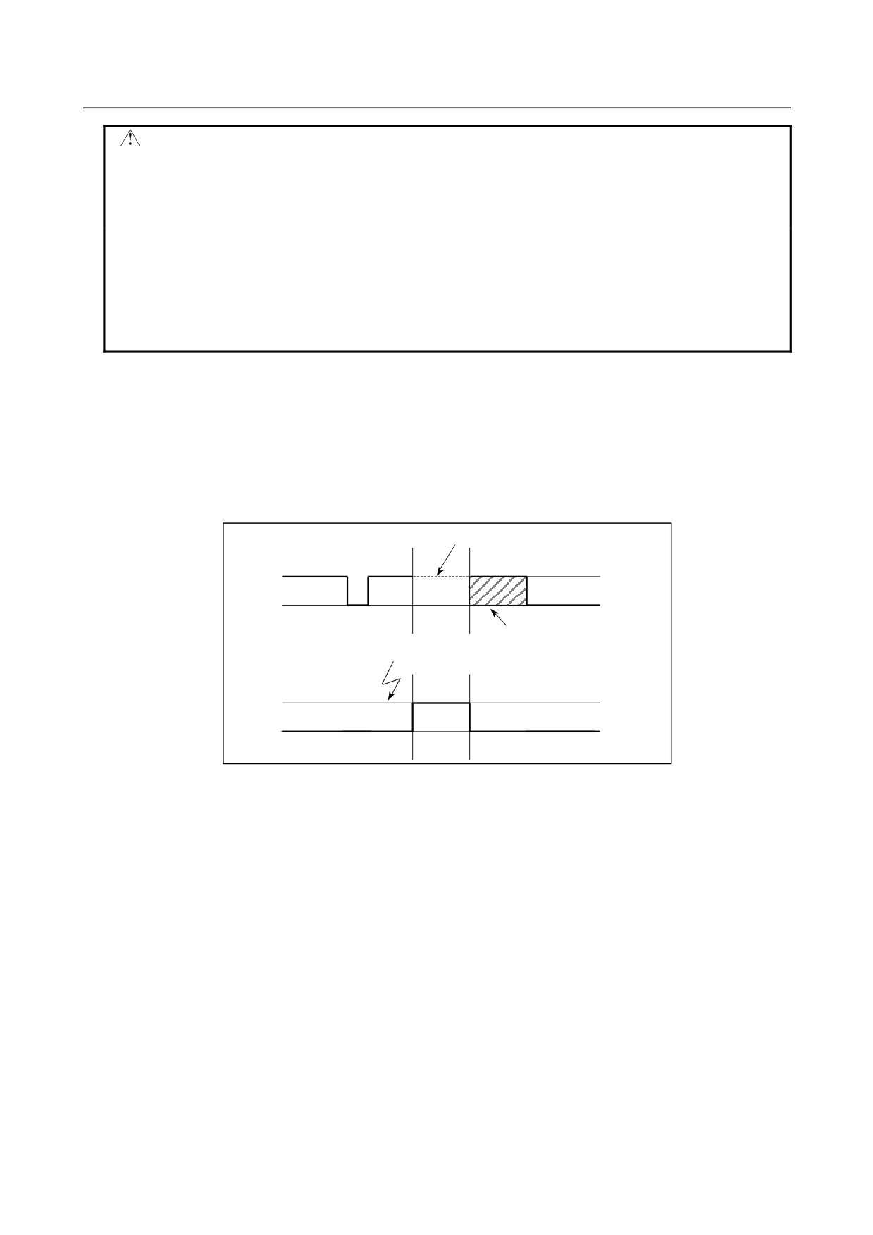
M96
M97
M96
1
0
Interrupt signal
(UINT)
Effective interrupt
input signal
When UINT is kept on
The interrupt signal (UINT) becomes valid after M96 is specified. Even when the signal is input in M97
mode, it is ignored. When the signal input in M97 mode is kept on until M96 is specified, a custom
macro interrupt is initiated as soon as M96 is specified (only when the status-triggered scheme is
employed); when the edge-triggered scheme is employed, the custom macro interrupt is not initiated even
when M96 is specified.
NOTE
For the status-triggered and edge-triggered schemes, see Item "Custom macro
interrupt signal (UINT)" of II-14.12.2.
- 233 -
14.CUSTOM MACRO
PROGRAMMING
B-64304EN/02
14.13.2 Details of Functions
Explanation
-
Subprogram-type interrupt and macro-type interrupt
There are two types of custom macro interrupts: Subprogram-type interrupts and macro-type interrupts.
The interrupt type used is selected by bit 5 (MSB) of parameter No.6003.
(a) Subprogram-type interrupt: When bit 5 (MSB) of parameter No.6003 is set to 1
An interrupt program is called as a subprogram.
This means that the levels of local variables remain unchanged before and after the interrupt.
This interrupt is not included in the nesting level of subprogram calls.
(b) Macro-type interrupt: When bit 5 (MSB) of parameter No.6003 is set to 0
An interrupt program is called as a custom macro.
This means that the levels of local variables change before and after the interrupt.
The interrupt is not included in the nesting level of custom macro calls.
When a subprogram call or a custom macro call is performed within the interrupt program, this call is
included in the nesting level of subprogram calls or custom macro calls.
Arguments cannot be passed from the current program even when the custom macro interrupt is a
macro-type interrupt. The local variables immediately after interruption are all cleared to null.
-
M codes for custom macro interrupt control
In general, custom macro interrupts are controlled by M96 and M97. However, these M codes, may
already being used for other purposes (such as an M function or M code for macro call) by some machine
tool builders.
For this reason, bit 4 (MPR) of parameter No.6003 is provided to set M codes for custom macro interrupt
control.
When specifying this parameter to use the custom macro interrupt control M codes set by parameters, set
parameters Nos.6033 and 6034 as follows:
Set the M code to enable custom macro interrupts in parameters Nos.6033, and set the M code to disable
custom macro interrupts in parameter 6034.
When specifying that parameter-set M codes are not used, M96 and M97 are used as the custom macro
control M codes regardless of the settings of parameters Nos.6033 and 6034.
The M codes used for custom macro interrupt control are processed internally (they are not output to
external units). However, in terms of program compatibility, it is undesirable to use M codes other than
M96 and M97 to control custom macro interrupts.
-
Custom macro interrupts and NC statements
When performing a custom macro interrupt, the user may want to interrupt the NC statement being
executed, or the user may not want to perform the interrupt until the execution of the current block is
completed. Bit 2 (MIN) of parameter No.6003)is used to select whether to perform interrupts even in
the middle of a block or to wait until the end of the block. The type of interrupt performed even in the
middle of a block is called type I and the type of interrupt performed at the end of the block is called type
II.
- 234 -
B-64304EN/02
PROGRAMMING
14.CUSTOM MACRO
CAUTION
For interrupt type I, operation after control is returned differs depending on
whether the interrupt program contains an NC statement.
When the program number block contains EOB (;), it is assumed to contain an
NC statement.
(Program containing an NC statement)
(Program containing no NC statement)
O0013 ;
O0013#101=#5041 ;
#101=#5041 ;
#102=#5042 ;
#102=#5042 ;
#103=#5043 ;
#103=#5043 ;
M99 ;
M99 ;
Type I (when an interrupt is performed even in the middle of a block)
(i)
When the interrupt signal (UINT) is input, any movement or dwell being performed is stopped
immediately and the interrupt program is executed.
(ii)
If there are NC statements in the interrupt program, the command in the interrupted block is lost and
the NC statement in the interrupt program is executed. When control is returned to the interrupted
program, the program is restarted from the next block after the interrupted block.
(iii)
If there are no NC statements in the interrupt program, control is returned to the interrupted program
by M99, then the program is restarted from the command in the interrupted block.
Interrupted by macro interrupt
Execution in progress
Normal program
CNC command restart;
Interrupt signal
when there are no NC statements
(UINT) input
in the interrupt program
Execution in progress
Custom macro interrupt
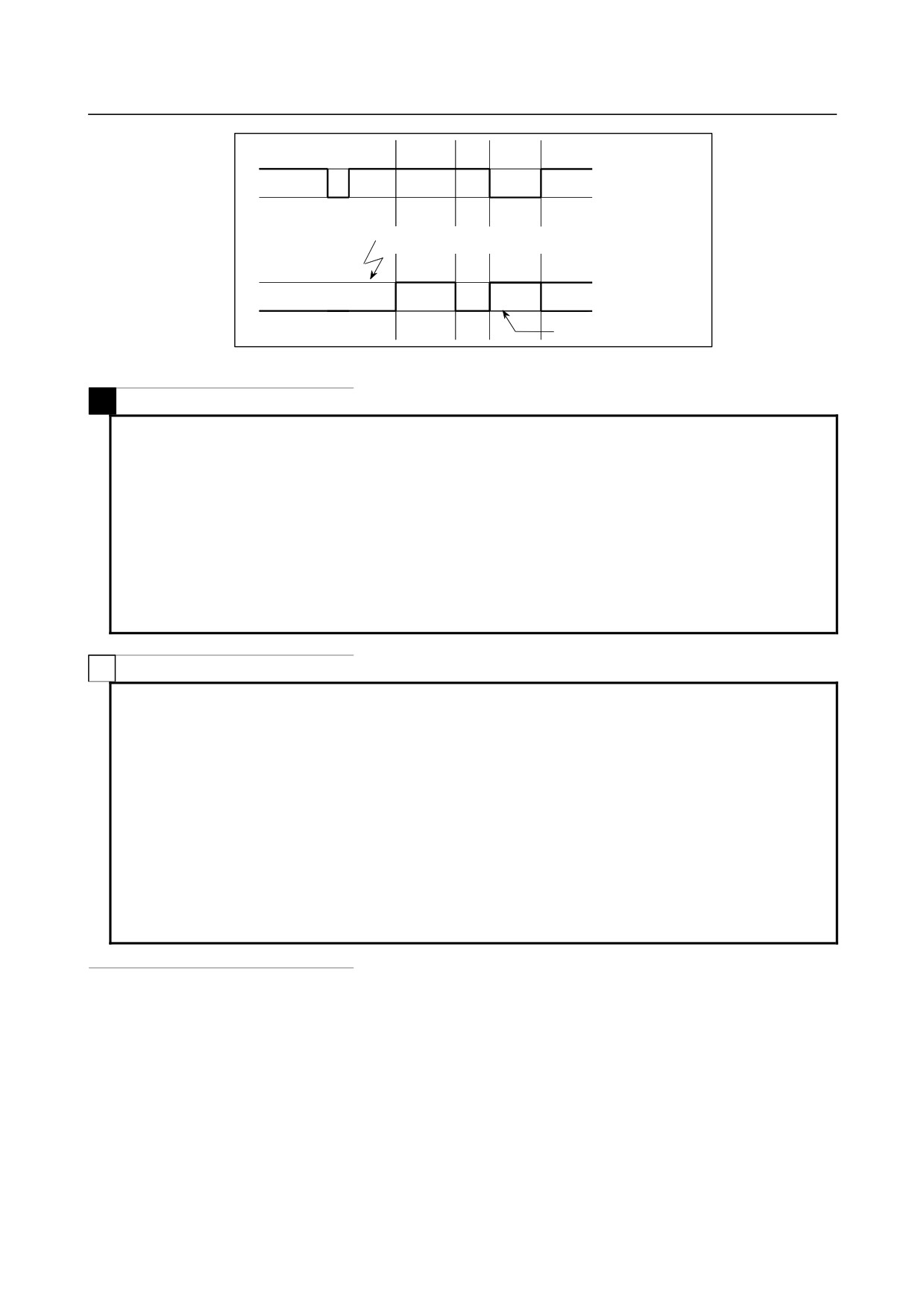
Fig. 14.13 (b) Custom macro interrupt and NC command (type I)
Type II (when an interrupt is performed at the end of the block)
(i)
If the block being executed is not a block that consists of several cycle operations such as a drilling
canned cycle and automatic reference position return (G28), an interrupt is performed as follows:
When an interrupt signal (UINT) is input, macro statements in the interrupt program are executed
immediately unless an NC statement is encountered in the interrupt program. NC statements are
not executed until the current block is completed.
(ii)
If the block being executed consists of several cycle operations, an interrupt is performed as follows:
When the last movement in the cycle operations is started, macro statements in the interrupt program
are executed unless an NC statement is encountered. NC statements are executed after all cycle
operations are completed.
- 235 -
14.CUSTOM MACRO
PROGRAMMING
B-64304EN/02
Execution in progress
Normal program
Interrupt signal (UINT) input
Execution in progress
Custom macro interrupt
NC statement in the interrupt
program
Fig. 14.13 (c) Custom macro interrupt and NC command (type II)
M
NOTE
During execution of a program for cycle operations, interrupt type II is performed
regardless of whether bit 2 (MIN) of parameter No. 6003 is set to 0 or 1. Cycle
operations are available for the following functions:
<1> Automatic reference position return
<2> Cutter compensation (generating multiple blocks using the specified block
such as when the tool moves around the outside of an acute angle)
<3> Canned cycle
<4> Automatic tool length measurement
<5> Normal direction control
T
NOTE
During execution of a program for cycle operations, interrupt type II is performed
regardless of whether bit 2 (MIN) of parameter No. 6003 is set to 0 or 1. Cycle
operations are available for the following functions:
<1> Automatic reference position return
<2> Tool nose radius compensation (generating multiple blocks using the
specified block such as when the tool moves around the outside of an acute
angle)
<3> Canned cycle (No interruption type custom macro can be used during
execution of a multiple repetitive canned turning cycle, however.)
<4> Automatic tool compensation
<5> Chamfering/corner R
-
Conditions for enabling and disabling the custom macro interrupt signal
The interrupt signal becomes valid after execution starts of a block that contains M96 for enabling custom
macro interrupts. The signal becomes invalid when execution starts of a block that contains M97.
While an interrupt program is being executed, the interrupt signal becomes invalid. The signal become
valid when the execution of the block that immediately follows the interrupted block in the main program
is started after control returns from the interrupt program. In type I, if the interrupt program consists of
only macro statements, the interrupt signal becomes valid when execution of the interrupted block is
started after control returns from the interrupt program.
- 236 -
B-64304EN/02
PROGRAMMING
14.CUSTOM MACRO
-
Custom macro interrupt signal (UINT)
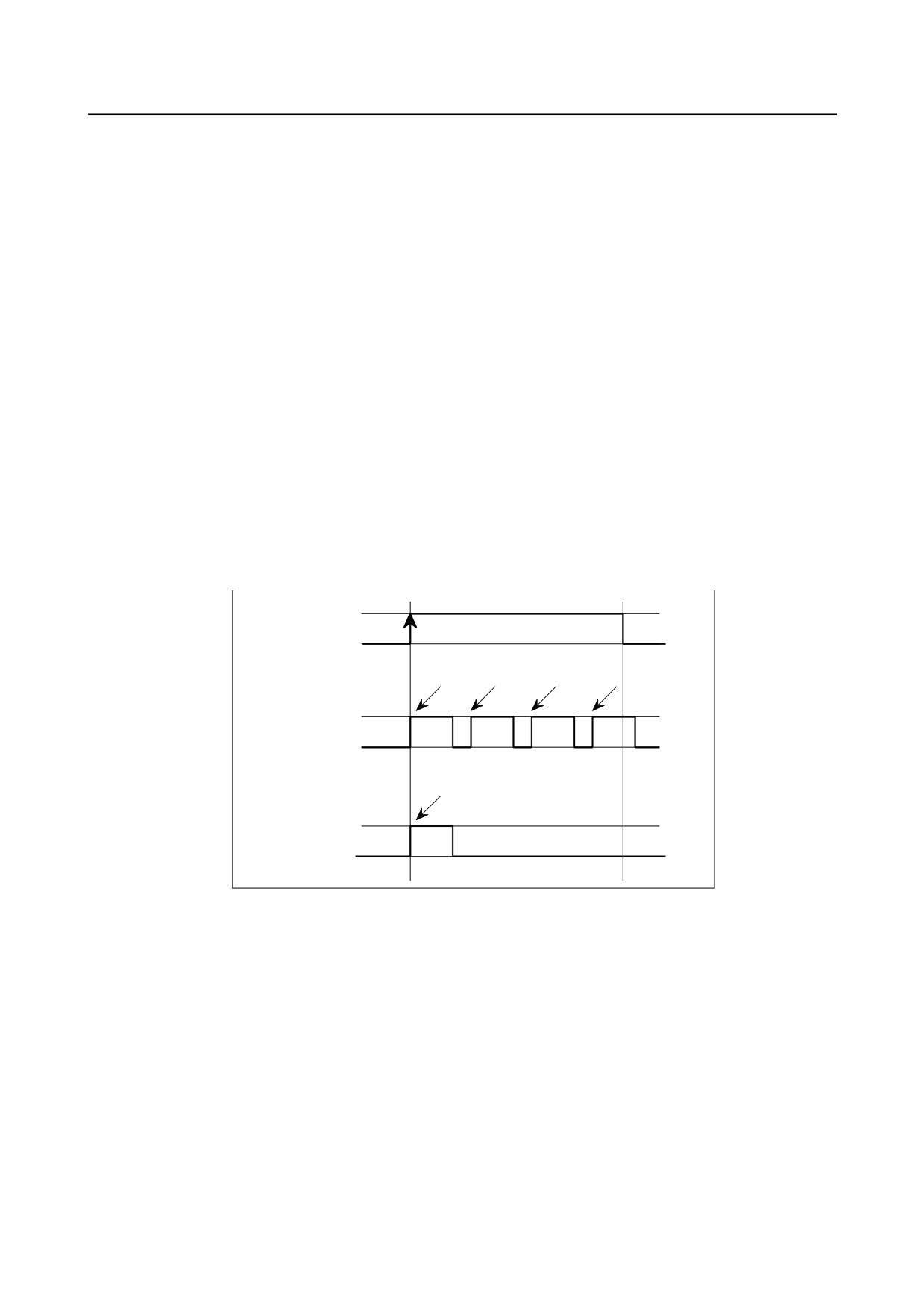
There are two schemes for custom macro interrupt signal (UINT) input: The status-triggered scheme
and edge-triggered scheme. When the status-triggered scheme is used, the signal is valid when it is on.
When the edge triggered scheme is used, the signal becomes valid on the rising edge when it switches
from off to on status.
One of the two schemes is selected with bit 3 (TSE) of parameter No.6003.
When the status-triggered scheme is selected by this parameter, a custom macro interrupt is generated if
the interrupt signal (UINT) is on at the time the signal becomes valid. By keeping the interrupt signal
(UINT) on, the interrupt program can be executed repeatedly.
When the edge-triggered scheme is selected, the interrupt signal (UINT) becomes valid only on its rising
edge. Therefore, the interrupt program is executed only momentarily (in cases when the program
consists of only macro statements). When the status-triggered scheme is inappropriate, or when a
custom macro interrupt is to be performed just once for the entire program (in this case, the interrupt
signal may be kept on), the edge-triggered scheme is useful.
Except for the specific applications mentioned above, use of either scheme results in the same effects.
The time from signal input until a custom macro interrupt is executed does not vary between the two
schemes.
In the example shown in Fig 14.12 (d), an interrupt is executed four times when the status-triggered
scheme is used; when the edge-triggered scheme is used, the interrupt is executed just once.
1
0
Interrupt signal (UINT)
Interrupt
Interrupt
Interrupt
execution execution execution
Interrupt
execution
Status-triggered scheme
Interrupt execution
Edge-triggered scheme
Fig. 14.13 (d) Custom macro interrupt signal
-
Return from a custom macro interrupt
To return control from a custom macro interrupt to the interrupted program, specify M99. A sequence
number in the interrupted program can also be specified using address P. If this is specified, the
program is searched from the beginning for the specified sequence number. Control is returned to the
first sequence number found.
- 237 -
14.CUSTOM MACRO
PROGRAMMING
B-64304EN/02
NOTE
If a block containing M99 is alone or has address O, N, P, L, or M only, this block
is programmatically assumed to be the same as the previous block. Therefore,
a single-block stop does not occur for this block. In terms of programming, the
following <1> and <2> are basically the same.
(The difference is whether Gxx
is executed before M99 is recognized.)
<1>
Gxx Xxxx ;
M99 ;
<2>
Gxx Xxxx M99 ;
-
Custom macro interrupt and modal information
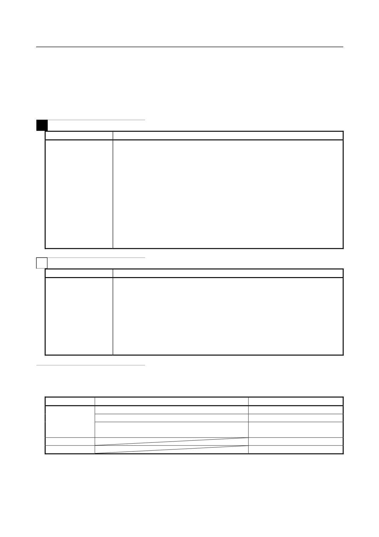
A custom macro interrupt is different from a normal program call. It is initiated by an interrupt signal
(UINT) during program execution. In general, any modifications of modal information made by the
interrupt program should not affect the interrupted program.
For this reason, even when modal information is modified by the interrupt program, the modal
information before the interrupt is restored when control is returned to the interrupted program by M99.
When control is returned from the interrupt program to the interrupted program by M99 Pyyyy, however,
modal information can again be controlled by the program. In this case, the new continuous information
modified by the interrupt program is passed to the interrupted program.
In this case, take the following action as required:
<1> The interrupt program provides modal information to be used after control is returned to the
interrupted program.
<2> After control is returned to the interrupted program, modal information is specified again as
necessary.
{ ΔΔΔΔ
M96 Pxxxx;
{ xxxx;
Interrupt signal (UINT)
Modify modal information
(Without P specification)
Modal information remains
unchanged before and after
M99 (Pyyyy);
the interrupt.
(With P specification)
Nyyyy;
The new modal information modified by the interrupt program is present.
Fig. 14.13 (e) Custom macro interrupt and modal information
Modal information when control is returned by M99
The modal information present before the interrupt becomes valid. The new modal information
modified by the interrupt program is made invalid.
- 238 -
B-64304EN/02
PROGRAMMING
14.CUSTOM MACRO
Modal information when control is returned by M99 Pyyyy
The new modal information modified by the interrupt program remains valid even after control is
returned.
Modal information which was valid in the interrupted block
The old modal information which was valid in the interrupted block can be read using custom macro
system variables #4401 to #4530.
M
System variable
Modal information which was valid when a custom macro interrupt was generated
#4401
G code (group 01)
:
:
#4430
G code (group 30)
#4502
B code
#4507
D code
#4508
E code
#4509
F code
#4511
H code
#4513
M code
#4514
Sequence number
#4515
Program number
#4519
S code
#4520
T code
#4530
Additional workpiece coordinate system number
T
System variable
Modal information which was valid when a custom macro interrupt was generated
#4401
G code (group 01)
:
:
#4430
G code (group 30)
#4508
E code
#4509
F code
#4513
M code
#4514
Sequence number
#4515
Program number
#4519
S code
#4520
T code
-
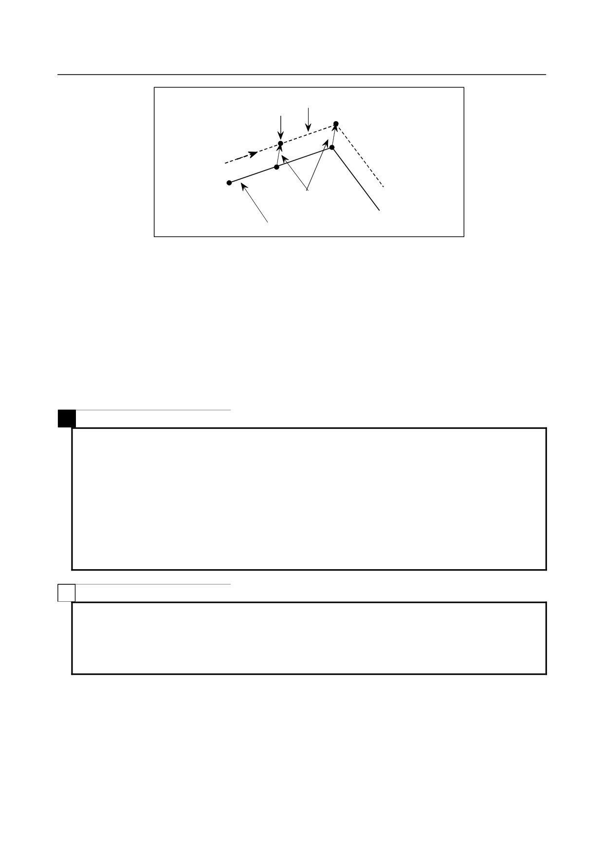
System variables (position information values) for the interrupt program
Position information can be read as follows.
Macro variable
Condition
Position information value
#5001 or above
Until the first NC statement appears
Coordinates of point A
After an NC statement with no move command appears
Coordinates of point A'
After an NC statement with a move command appears
Coordinates of the end point of the
move command
#5021 or above
Machine coordinates of point B'
#5041 or above
Workpiece coordinates of point B'
- 239 -
14.CUSTOM MACRO
PROGRAMMING
B-64304EN/02
Tool center path
Interrupt generated
B
B
A
A’
Offset vector
Programmed tool path
-
Custom macro interrupt and custom macro modal call
When the interrupt signal (UINT) is input and an interrupt program is called, the custom macro modal
call is canceled (G67). However, when G66 is specified in the interrupt program, the custom macro
modal call becomes valid. When control is returned from the interrupt program by M99, the modal call
is restored to the state it was in before the interrupt was generated. When control is returned by M99
Pyyyy ;, the modal call in the interrupt program remains valid.
-
Custom macro interrupt and program restart
In program restart, when the interrupt signal (UINT) is input during dry run recovery after a search, the
interrupt program is called after restart of all axes is completed.
That is, interrupt type II is assumed regardless of the parameter setting.
M
NOTE
1 Alarm PS1101 occurs in the following cases:
<1>An interrupt is generated in the programmable mirror image (G51.1) mode
and another G51.1 is specified in the interrupt program.
<2>An interrupt is generated in the coordinate system rotation (G68) mode and
another G68 is specified in the interrupt program.
<3>An interrupt is generated in the scaling (G51) mode and another G51 is
specified in the interrupt program.
2 In program restart, do not input the interrupt signal (UINT) during dry run
recovery after a search.
T
NOTE
1 No interruption type custom macro can be used during execution of a multiple
repetitive canned turning cycle.
2 In program restart, do not input the interrupt signal (UINT) during dry run
recovery after a search.
- 240 -

15.PROGRAMMABLE
B-64304EN/02
PROGRAMMING
PARAMETER INPUT (G10)
15 PROGRAMMABLE PARAMETER INPUT
(G10)
Overview
The values of parameters and pitch error compensation data can be entered in a program. This function is
used for setting pitch error compensation data when attachments are changed or the maximum cutting
feedrate or cutting time constants are changed to meet changing machining conditions.
Format
-
Parameter entry mode
G10 L52 ;
Parameter entry mode setting
N_ (Q_) R_ ;
For parameters other than the axis type or spindle type
N_ P_ (Q_) R_ ;
For axis type or spindle type parameters
:
G11 ;
Parameter entry mode cancel
N_
: Parameter number
R_
: Parameter setting value (Leading zeros can be omitted.)
(Q_) : Bit number 0 to 7 (to be set when a bit type parameter is input)
(Enabled when bit 4 (G1B) of parameter No.3454 = 1.)
P_
: Axis number 1 to maximum controlled axis number (to be specified when an axis
type parameter or spindle type parameter is specified)
NOTE
G10L52 cannot be used to enter pitch error compensation data.
-
Pitch error compensation data entry mode
G10 L50 ; Pitch error compensation data entry mode setting
N_ R_ ; Pitch error compensation data entry
:
:
G11 ;
Pitch error compensation data entry mode cancel
N_ : Compensation position number for pitch errors compensation +10,000
R_ : Pitch error compensation data
NOTE
G10L50 cannot be used to enter parameter.
Explanation
-
Setting value (R_)
Do not use a decimal point in the setting (R_) of a parameter or pitch error compensation data.
To change a bit type parameter if bit 4 (G1B) of parameter No. 3454 is 1, specify 0 or 1. If a value other
than 0 and 1 is specified, alarm PS1144, "G10 FORMAT ERROR", is issued.
As the value of R, a custom macro variable can be used.
When a parameter of real type is used, set an integer value in (R_) according to the increment system of
the parameter.
- 241 -
15. PROGRAMMABLE
PARAMETER INPUT (G10)
PROGRAMMING
B-64304EN/02
-
Bit number (Q_)
Bit number (Q_) is effective if bit 4 (G1B) of parameter No. 3454 is 1. To set a bit type parameter, set a
number in the range of 0 to 7.
A custom macro variable can be used as the value of Q.
-
Axis number (P_)
As the axis number (P_), specify the order of a controlled axis to be displayed on the CNC display screen,
by using an axis type parameter.
For example, specify P2 for the control axis which is displayed second.
For a spindle type also, specify the order of an axis to be display on the CNC display screen.
A custom macro variable can be used as the value of P.
WARNING
1 Do not fail to perform reference position return manually after changing the pitch
error compensation data or backlash compensation data. Without this, the
machine position can deviate from the correct position.
2 The canned cycle mode must be cancelled before entering of parameters. When
not cancelled, the drilling motion may be activated.
CAUTION
Compatibility with the Series 0i-C:
This model has parameters that are not compatible with the Series 0i-C.
So, before using this function, make a check according to the Parameter Manual
(B-64310EN) of this model.
NOTE
Other NC statements cannot be specified while in parameter input mode.
Example
1.
Set bit 2 (SBP) of bit type parameter No. 3404 (when the bit 4 (G1B) of parameter No. 3454 is set to
0)
G10 L52 ;
Parameter entry mode
N3404 R00000100 ;
SBP setting
G11 ;
Cancel parameter entry mode
2.
Set bit 2 (SBP) of bit type parameter No. 3404 (when the bit 4 (G1B) of parameter No. 3454 is set to
1)
G10 L52 ;
Parameter entry mode
N3404 Q2 R1 ;
SBP setting
G11 ;
Cancel parameter entry mode
3.
Change the values for the Z-axis (3rd axis) and A-axis (4th axis) in axis type parameter No. 1322
(the coordinates of stored stroke limit 2 in the positive direction for each axis).
(When the increment systems for the
3rd and
4th axes are IS-B and millimeter machine,
respectively)
G10 L52 ;
Parameter entry mode
N1322 P3 R4500 ;
Change the value for the Z-axis to 4.500
N1322 P4 R12000 ; Change the value for the A-axis to 12.000
G11 ;
Cancel parameter entry mode
- 242 -
15.PROGRAMMABLE
B-64304EN/02
PROGRAMMING
PARAMETER INPUT (G10)
4.
Change compensation point numbers 10 and 20 of pitch error compensation.
G10 L50 ;
Pitch error compensation data entry mode
N10010 R1 ;
Change the compensation point number from 10 to 1
N10020 R5 ;
Change the compensation point number from 20 to 5
G11 ;
Pitch error compensation data entry mode
- 243 -
16. HIGH-SPEED CUTTING
FUNCTIONS
PROGRAMMING
B-64304EN/02
16 HIGH-SPEED CUTTING FUNCTIONS
Chapter 16, "HIGH-SPEED CUTTING FUNCTIONS", consists of the following sections:
16.1 ADVANCED PREVIEW CONTROL (T SERIES) / AI ADVANCED PREVIEW CONTROL
(M SERIES) / AI CONTOUR CONTROL (II) (M SERIES)
244
16.2 MACHINING CONDITION SELECTING FUNCTION
261
16.3 MACHINING QUALITY LEVEL ADJUSTMENT (M Series)
262
16.4 JERK CONTROL (M Series)
263
16.1 ADVANCED PREVIEW CONTROL (T SERIES) / AI
ADVANCED PREVIEW CONTROL (M SERIES) / AI
CONTOUR CONTROL (II) (M SERIES)
Overview
Advanced preview control (T series), AI advanced preview control (M series), and AI contour control (II)
(M series) are intended for high-speed, high-precision machining. The use of these functions suppresses
the acceleration/deceleration delay that tends to increase as the feedrate becomes faster, as well as the
delay in the servo system, reducing the machining profile error.
The following table shows the functions included in these functions.
APC
AI APC
AICC
AICC II
Model
0i-TD
0i Mate-MD
0i-MD
0i-MD
0i-MD
Basic/Option
Option
Basic
Option
Option
Look-ahead block count
1
12
20
40
200
Look-ahead linear acceleration/
○
○
○
○
deceleration before interpolation
Look-ahead bell-shaped acceleration/
-
-
☆
☆
deceleration before interpolation
Function for changing time constant of
-
-
☆
☆
bell-shaped acceleration/deceleration
Advanced feed forward
○
○
○
○
Acceleration setting for each axis
○
○
○
○
Speed control based on the feedrate
○
○
○
○
difference on each axis
Speed control with
○
○
○
○
acceleration in circular interpolation
Speed control with
-
○
○
○
the acceleration on each axis
Smooth speed control
-
-
-
○
Speed control with cutting load
-
-
-
○
Disregard of feedrate command
-
-
-
○
Jerk control
- Speed control with change of
acceleration on each Axis
-
-
-
☆
- Look-ahead smooth bell-shaped
acceleration/deceleration before Interpolation
Nano smoothing
-
-
-
☆
APC
: Advanced preview control
- 244 -

16.HIGH-SPEED CUTTING
B-64304EN/02
PROGRAMMING
FUNCTIONS
AI APC
: AI advanced preview control
AICC
: AI contour control
AICC II
: AI contour control II
-: Function not supported
○: Standard function
☆: Optional function
M
The function for changing time constant of bell-shaped acceleration/deceleration is included in
look-ahead bell-shaped acceleration/deceleration before interpolation.
The look-ahead bell-shaped acceleration/deceleration before interpolation is optional function.
Format
T
-
Advanced preview control
G08 P_ ;
P1 : Advanced preview control mode on
P0 : Advanced preview control mode off
NOTE
1 Always specify G08 in an independent block.
2 The advanced preview control mode is also cleared by the reset operation.
M
・AI advanced preview control/AI contour control (II)
G05.1 Q_ ;
Q1 : AI advanced preview control mode/AI contour control (II) mode on
Q0 : AI advanced preview control mode/AI contour control (II) mode off
NOTE
1 Always specify G05.1 in an independent block.
2 The AI advanced preview control/AI contour control (II) mode is also cleared by
the reset operation.
Explanation
-
Look-ahead acceleration/deceleration before interpolation
T
Acceleration/deceleration type of look-ahead acceleration/ deceleration before interpolation function is
look-ahead linear acceleration/deceleration before interpolation function.
M
There are two look-ahead acceleration/deceleration before interpolation functions - look-ahead linear
acceleration/deceleration before interpolation and look-ahead bell-shaped acceleration/ deceleration
before interpolation. Look-ahead bell-shaped acceleration/deceleration before interpolation offers more
smooth acceleration and deceleration.
- 245 -