FANUC Series 16i/160i/160is-MB, Series 18i/180i/180is-MB5, Series 18i/180i/180is-MB. Operator's Manual - page 39

12. GRAPHICS FUNCTION
OPERATION
B-63534EN/02
D Displaying the
Bit 5 (DPO) of parameter No. 6500 can be used to specify whether the
coordinates
coordinates of the current position are to be displayed on the tool path
drawing.
In background drawing mode, modal information F, S, and T is displayed,
together with the current position. If the [POS] soft key has been selected
for dynamic graphic display, however, F, S, and T are not displayed.
CAUTION
Once an alarm is issued during background drawing,
drawing is stopped and the alarm description is displayed
at the bottom right of the screen. To release the alarm state,
CAN
RESET
press the
MDI key. Note that pressing the
key
will also stop foreground machining if currently in progress.
Note, however, that bit 0 (RST) of parameter No. 8100 can
be used to specify that machining will not be stopped if the
key is pressed during background drawing.
RESET
1120

B-63534EN/02
OPERATION
13. HELP FUNCTION
HELP FUNCTION
13
The help function displays on the screen detailed information about
alarms issued in the CNC and about CNC operations. The following
information is displayed.
D Detailed information of
When the CNC is operated incorrectly or an erroneous machining
alarms
program is executed, the CNC enters the alarm state. The help screen
displays detailed information about the alarm that has been issued and
how to reset it. The detailed information is displayed only for a limited
number of P/S alarms. These alarms are often misunderstood and are
rather difficult to understand.
D Operation method
If you are not sure about a CNC operation, refer to the help screen for
information about each operation.
D Parameter table
When setting or referring to a system parameter, if you are not sure of the
number of the parameter, the help screen displays a list of parameter Nos.
for each function.
Help Function Procedure
Procedure
1
Press the
HELP
key on the MDI. HELP (INITIAL MENU) screen is
displayed.
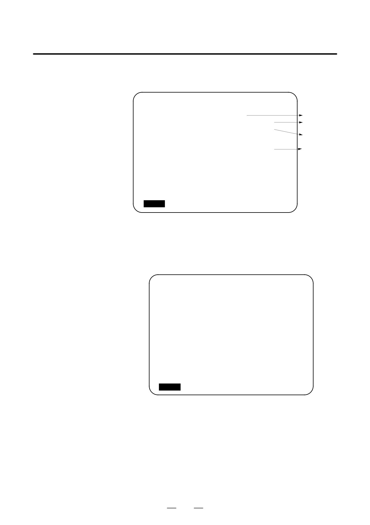
HELP (INITIAL MENU)
O1234
N00001
***** HELP *****
1. ALARM DETAIL
2. OPERATION METHOD
3. PARAMETER TABLE
S
0 T0000
MEM **** *** ***
10:12:25
[ ALM
][ OPR
][ PARA
][
][
]
Fig. 13 (a) HELP (INITIAL MENU) Screen
The user cannot switch the screen display from the PMC screen or
CUSTOM screen to the help screen. The user can return to the normal
CNC screen by pressing the
HELP
key or another function key.
1121
13. HELP FUNCTION
OPERATION
B-63534EN/02
ALARM DETAIL screen
2
Press soft key [ALM] on the HELP (INITIAL MENU) screen to display
detailed information about an alarm currently being
raised..
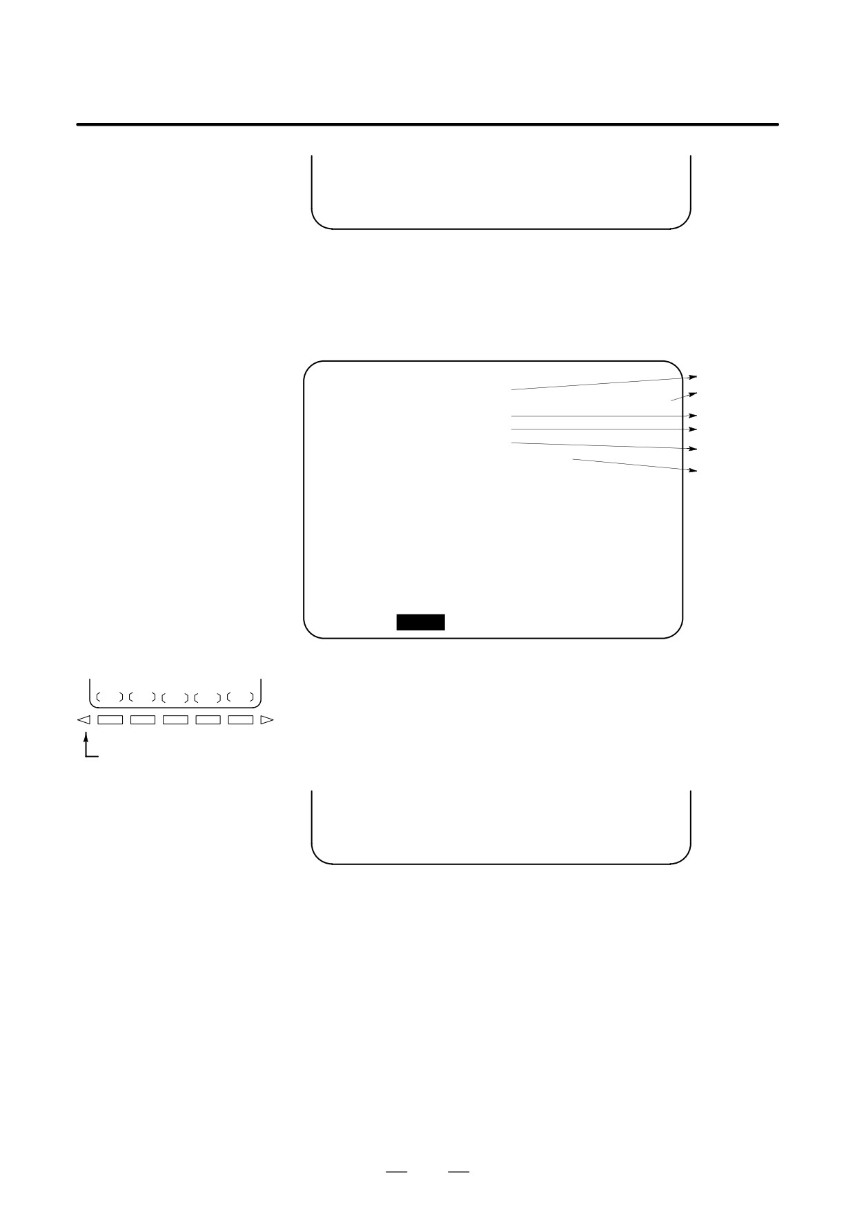
HELP (ALARM DETAIL)
O0010 N00001
NUMBER : 027
Alarm No.
M‘SAGE
: NO AXES COMMANDED IN G43/G44
Normal explana-
FUNCTION
: TOOL LENGTH COMPENSATION C
tion on alarm
ALARM
:
Function
IN TOOL LENGTH COMPENSATION TYPE C,
classification
NO AXIS IS DESIGNATED IN G43 & G44
BLOCKS. IN TOOL LENGTH COMPENSATION
Alarm details
TYPE C, IT TRIES TO LATCH ON TO
ANOTHER AXIS WITHOUT OFFSET CANCE-
LING.
>100
S
0 T0000
MEM **** *** ***
10:12:25
[ ALM
][ OPR
][ PARA
][
][
]
Fig. 13 (b) ALARM DETAIL Screen when P/S Alarm No. 27 is issued
Note that only details of the alarm identified at the top of the screen
are displayed on the screen.
If the alarms are all reset while the help screen is displayed, the alarm
displayed on the ALARM DETAIL screen is deleted, indicating that no
alarm is issued.
HELP
(ALARM DETAIL)
O1234 N00001
NUMBER
:
M‘SAGE
:
FUNCTION
:
ALARM
:
<<ALARM IS NOT GENERATED>>
ENTER THE DETAIL-REQUIRED ALARM NUMBER,
AND PRESS [SELECT] KEY
>100
S
0 T0000
MEM **** *** ***
10:12:25
[ ALM
][ OPR
][ PARA
][
][
]
Fig. 13 (c) ALARM DETAIL Screen when No Alarm is issued
1122

B-63534EN/02
OPERATION
13. HELP FUNCTION
3
To get details on another alarm number, first enter the alarm number,
then press soft key
[SELECT]. This operation is useful for
investigating alarms not currently being raised.
>100
S
0 T0000
MEM **** *** ***
10:12:25
[
][
][
][
][ SELECT ]
Fig. 13 (d) How to select each ALARM DETAILS
HELP (ALARM DETAIL)
O1234 N00001
NUMBER
: 100
M‘SAGE
: PARAMETER WRITE ENABLE
FUNCTION
:
ALARM
:
<<ALARM IS NOT GENERATED>>
>100
S
0 T0000
MEM **** *** ***
10:12:25
[
][
][
][
][ SELECT ]
Fig. 13 (e) ALARM DETAIL Screen when P/S alarm No. 100 is selected
OPERATION METHOD
4
To determine an operating procedure for the CNC, press the soft key
screen
[OPR] key on the HELP (INITIAL MENU) screen. The OPERATION
METHOD menu screen is then displayed. (See Fig. 13 (f).)
HELP (OPERATION METHOD)
O1234
N00001
1. PROGRAM EDIT
2. SEARCH
3. RESET
4. DATA INPUT WITH MDI
5. DATA INPUT WITH TAPE
6. OUTPUT
7. INPUT WITH FANUC CASSETTE
8. OUTPUT WITH FANUC CASSETTE
9. MEMORY CLEAR
S
0 T0000
MEM **** *** ***
10:12:25
[ ALM
][ OPR
][ PARA
][
][
]
Fig. 13 (f) OPERATION METHOD Menu Screen
To select an operating procedure, enter an item No. from the keyboard
then press the [SELECT] key.
1123
13. HELP FUNCTION
OPERATION
B-63534EN/02
>1
S
0 T0000
MEM **** *** ***
10:12:25
[
][
][
][
][ SELECT ]
Fig. 13 (g) How to select each OPERATION METHOD screen
When “1. PROGRAM EDIT” is selected, for example, the screen in
Figure 13 (g) is displayed.
On each OPERATION METHOD screen, it is possible to change the
displayed page by pressing the PAGE key. The current page No. is
shown at the upper right corner on the screen.
Each item
HELP (OPERATION METHOD)
01234 N00001
Page/maximum
<< 1. PROGRAM EDIT >>
1/4
page
*DELETE ALL PROGRAMS
Operation
Set mode
MODE
: EDIT
SCREEN
: PROGRAM
Operation location
OPR
: (O-9999) - <DELETE>
Operating
procedure
*DELETE ONE PROGRAM
MODE
: EDIT
SCREEN
: PROGRAM
OPR
: (O+PROGRAM NUMBER) - <DELETE>
>_
S
0 T0000
MEM **** *** ***
10:12:25
[ ALM
][ OPR
][ PARA
][
][
]
Fig. 13 (h) Selected OPERATION METHOD screen
5
To return to the OPERATION METHOD menu screen, press the
RETURN MENU key to display “[OPR]” again, and then press the
[OPR] key again.
To directly select another OPERATION METHOD screen on the
RETURN MENU key
screen shown in Figure 13 (h), enter an item No. from the keyboard
and press the [SELECT] key.
>3
S
0 T0000
MEM **** *** ***
10:12:25
[
][
][
][
][ SELECT ]
Fig. 13 (i) How to select another OPERATION METHOD screen
PARAMETER TABLE
6
If you are not sure of the No. of a system parameter to be set, or to refer
screen
to a system parameter, press the [PARA] key on the HELP (INITIAL
MENU) screen. A list of parameter Nos. for each function is
displayed.
(See Figure 13 (j).)
It is possible to change the displayed page on the parameter screen.
The current page No. is shown at the upper right corner on the screen.
1124
B-63534EN/02
OPERATION
13. HELP FUNCTION
HELP (PARAMETER TABLE)
01234 N00001
1/4
* SETTEING
(No. 0000∼)
* READER/PUNCHER INTERFACE
(No. 0100∼)
* AXIS CONTROL
/SETTING UNIT
(No. 1000∼)
* COORDINATE SYSTEM
(No. 1200∼)
* STROKE LIMIT
(No. 1300∼)
* FEED RATE
(No. 1400∼)
* ACCEL/DECELERATION CTRL
(No. 1600∼)
* SERVORELATED
(No. 1800∼)
* DI/DO
(No. 3000∼)
>_
S
0 T0000
MEM **** *** ***
10:12:25
[ ALM
][ OPR
][ PARA
][
][
]
Fig. 13 (j) PARAMETER TABLE screen
7
To exit from the help screen, press the
HELP
key or another function
key.
Explanation
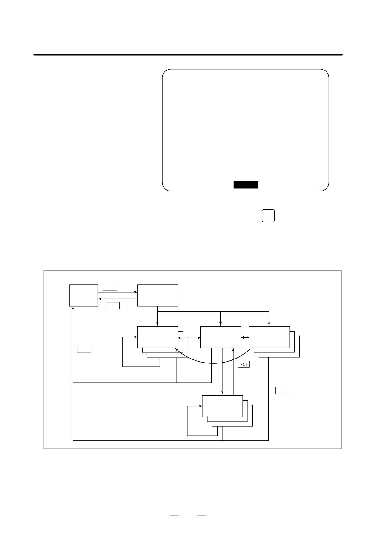
D Configuration of the Help Screen
HELP
key
HELP
CNC
INITIAL MENU
screen
screen
HELP
key
or
[ALAM]
[OPR]
[PARA]
function key
ALARM
OPERATION
PARAME-
DETAIL
METHOD
TER TABLE
screen
screen
screen
PAGE key
HELP
key
or
function key
(NO.)+[SELECT]
[OPR]
(NO.)+[SELECT]
HELP
key
Each opera-
or
tion instruc-
function key
tion screen
(NO.)+[SELECT]
1125

14. SCREEN HARDCOPY
OPERATION
B-63534EN/02
SCREEN HARDCOPY
14
The screen hardcopy function outputs the information displayed on the
CNC screen as 640*480-dot bitmap data. This function makes it possible
to produce a hard copy of a still image displayed on the CNC.
The created bitmap data can be displayed on a PC.
Screen Hardcopy Procedure
1
Check the parameter settings. To use the screen hardcopy function,
set bit 7 (HDC) of parameter 3301 to 1 and parameter 20 (I/O channel
selection) to 4 (memory card I/F). Set other relative parameters (bits
0, 2, and 3 of parameter 3301) as needed. In a multipath system, set
the parameters for each path.
2
Insert a memory card.
3
To start the function, set hardcopy start signal HDREQ <G067#7> to
1. Alternatively, hold down the [SHIFT] key for five seconds.
4
To end the function, press the [CAN] key. Alternatively, set hard
copy stop signal HDABT <G067#6> to 1.
5
While the screen hardcopy operation is in progress, the hardcopy in
progress signal <F061#3> is tied to 1. For several tens of seconds (or
several seconds, for a monochrome LCD) before the hardcopy
operation ends, the screen image stands still.
6
When the screen hardcopy operation is completed, the hardcopy in
progress signal <F061#3> goes 0.
Supplementary
While the screen hardcopy operation is in progress, the screen image
explanation
keeps still. This means that the clock displayed on the screen indicates
the beginning and end of the operation. When the clock stops counting
seconds, the hard copy operation starts. The clock resumes counting
seconds when the screen hard copy operation ends.
1126

B-63534EN/02
OPERATION
14. SCREEN HARDCOPY
NOTE
1
During the screen hardcopy operation, key input is disabled
for several tens of seconds. Until the screen hardcopy
operation ends, the screen image lies still. During this
period, the hardcopy in progress signal <F061#3> is tied to
1. No other signal is output. Avoid turning off the power
indiscriminately during that period.
2
If the [SHIFT] or [CAN] key is customized by C executor, for
instance, the screen hardcopy operation may disable the
[SHIFT] or [CAN] key.
3
A normal hard copy may not be produced while the screen
image is moving.
Limitations
A hard copy of the following screens cannot be produced.
1
Screen of the FS-160i/180i/210i (CNC with personal computer
function)
2
System alarm screen
3
Screen while RS-232-C is being used
4
Screen during automatic or manual operation (A hard copy can be
produced in a rest of the operation.)
Screen hardcopy function can not be used with the 160i/180i/160is/180is.
File name
The bitmap files created by the screen hardcopy function are named as
follows, in order in which they are created after power-up:
‘HDCPY000.BMP’ (Name of the first hardcopy file created after
power-up)
‘HDCPY001.BMP’ (Name of the second hardcopy file created after
power-up)
:
:
‘HDCPY099.BMP’
NOTE
1
A screen hardcopy file produced after the file HDCPY099.
BMP is output will be named as HDCPY000.BMP.
2
If a BMP file output by the screen hardcopy function has the
same name as a file present on a memory card, the file on
the memory card is overwritten unconditionally.
3
When the hardcopy function is carried out after power is
turned off and on again, the first output file is named as
HDCPY000.BMP again. If the inserted memory card has a
file having the same name, the file is unconditionally
overwritten. Note this when continuously producing hard
copies of various screens.
1127

14. SCREEN HARDCOPY
OPERATION
B-63534EN/02
Colors of data
The number of colors used in created bitmap data depend on the display
control card, the LCD hardware, and the display mode of the CNC screen.
Table 14 (a) indicates the relationships.
Table 14 (a) Colors of BMP data created by the screen hardcopy function
LCD
CNC screen
Colors
Colors used in created
Remarks
hardware
display
displayed
BMP data
mode
on CNC
Monochrome
—
2 colors
2 colors
Shades of gray are not supported.
LCD
Color LCD
VGA-comp
Character:
When bit 0 of parameter
Most CNC screens use this mode. Note
atible mode
16 colors
3301 is set to 0: 256 colors
that colors may not be normally displayed
Graphic:
When bit 0 of parameter
in the 16-color mode.
16 colors
3301 is set to 1: 16 colors
VGA mode
256 colors
256 colors
A special screen can be prepared by C
executor, for instance.
Data size
Table 14 (b) indicates the sizes of bitmap data created by the screen
hardcopy function.
Table 14 (b) Sizes of bitmap data created by the screen hardcopy
function
Bitmap colors
File size (bytes)
Monochrome (2 colors)
38,462
Color (16 colors)
153,718
Color (256 colors)
308,278
Alarm message
If bit 2 (HCA) of parameter 3301 is set to 1, an alarm message can be
output when the hardcopy operation ends in failure.
(P/S alarm Nos. 5212 to 5214)
For descriptions of these alarms, see APPENDIX G, “ALARM LIST.”
1128
IV. MAINTENANCE

B-63534EN/02
MAINTENANCE
1. METHOD OF REPLACING BATTERY
METHOD OF REPLACING BATTERY
1
This chapter describes how to replace the CNC backup battery and
absolute pulse coder battery. This chapter consists of the following
sections:
1.1 REPLACING BATTERY FOR LCD-MOUNTED TYPE i
SERIES
1.2 REPLACING THE BATTERY FOR STAND-ALONE TYPE i
SERIES
1.3 BATTERY IN THE CNC DISPLAY UNIT WITH PC
FUNCTIONS (3 VDC)
1.4 BATTERY FOR SEPARATE ABSOLUTE PULSE CODERS
(6 VDC)
1.5 BATTERY FOR BUILT-IN ABSOLUTE PULSE CODER
(6 VDC)
Battery for memory
Part programs, offset data, and system parameters are stored in CMOS
backup
memory in the control unit. The power to the CMOS memory is backed
up by a lithium battery mounted on the front panel of the control unit.
Therefore, the above data is not lost even if the main battery fails. The
backup battery is installed in the control unit prior to being shipped from
the factory. This battery can provide backup for the memory contents for
about a year.
When the battery voltage falls, alarm message “BAT” blinks on the LCD
display and the battery alarm signal is output to the PMC. When this
alarm is displayed, replace the battery as soon as possible. In general, the
battery can be replaced within one or two weeks of the alarm first being
issued. This, however, depends on the system configuration.
If the battery voltage subsequently drops further, backup of memory can
no longer be provided. Turning on the power to the control unit in this
state causes system alarm 910 (SRAM parity alarm) to be issued because
the contents of memory are lost. Replace the battery, clear the entire
memory, then reenter the data.
Replace the memory backup battery within a few minutes while the
control unit is brought off.
The following two kinds of batteries can be used.
D Lithium battery, incorporated into the CNC control unit.
D Two alkaline dry cells (size D) in an external battery case.
NOTE
A lithium battery is installed as standard at the factory.
1131
1. METHOD OF REPLACING BATTERY
MAINTENANCE
B-63534EN/02
1.1
REPLACING
BATTERY FOR
LCD-MOUNTED
TYPE i SERIES
D Replacement procedure
When a lithium battery is used
Prepare a new lithium battery
(ordering code: A02B-0200-K102
(FANUC specification: A98L-0031-0012)).
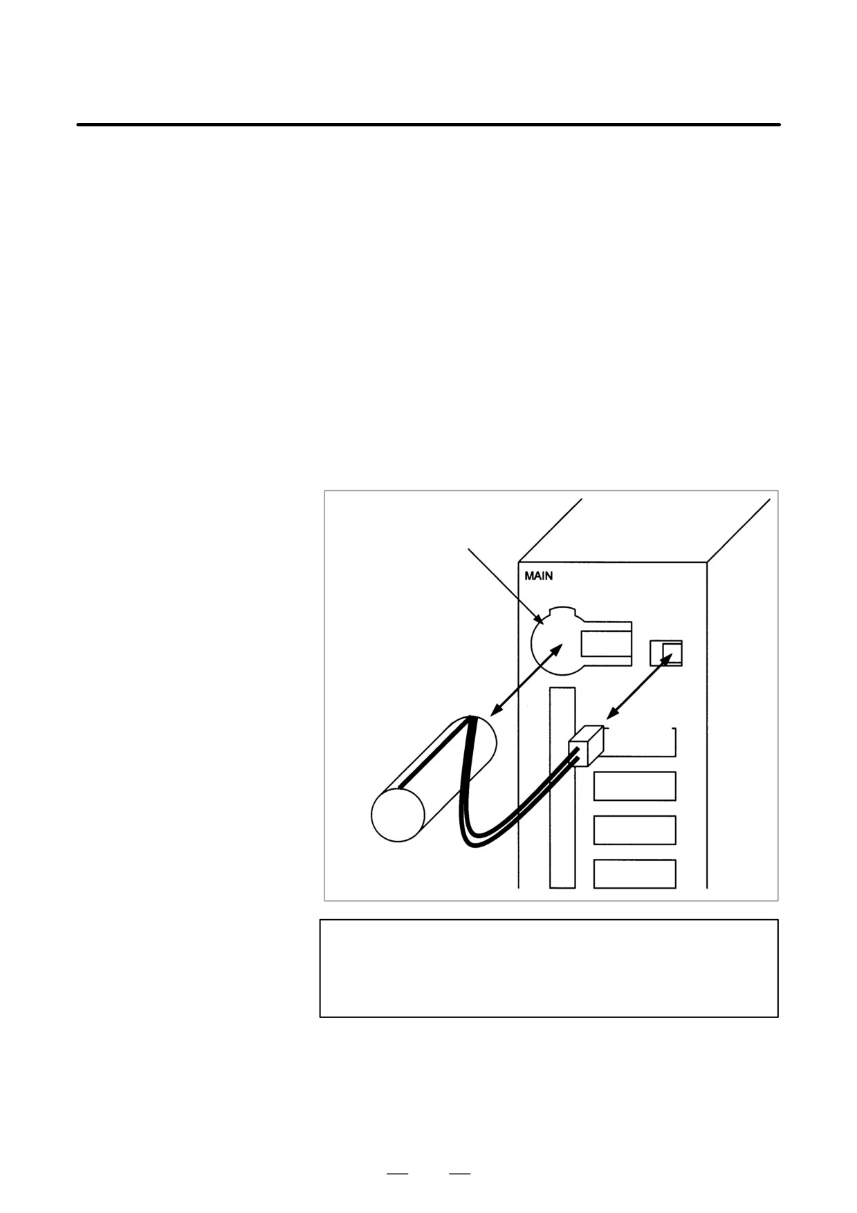
1) Turn on the power to the CNC. After about 30 seconds, turn off the
power.
2) Remove the old battery from the top of the CNC control unit.
First, unplug the battery connector, then take the battery out of its
case.
The battery case of a control unit without option slots is located at the
top end of the unit as shown in the figure of the previous page. The
battery case of a control unit with 2 slots or 4 slots is located in the
central area of the top of the unit (between fans).
3) Insert a new battery and reconnect the connector.
Battery case
Connector
Lithium battery
A02B-0200-K102
WARNING
Using other than the recommended battery may result in the
battery exploding. Replace the battery only with the
specified battery (A02B-0200-K102).
1132
B-63534EN/02
MAINTENANCE
1. METHOD OF REPLACING BATTERY
CAUTION
Steps 1) to 3) should be completed within 30 minutes. Do
not leave the control unit without a battery for any longer
than the specified period. Otherwise, the contents of
memory may be lost.
If steps 1) to 3) may not be completed within 30 minutes,
save all contents of the CMOS memory to the memory card
beforehand. Thus, if the contents of the CMOS memory are
lost, the contents can be restored easily.
For the method of operation, refer to Maintenance manual
(B-63525EN).
When discarding a battery, observe the applicable ordinances or other
rules of your local government. Also, cover the terminals of the battery
with vinyl tape or the like to prevent a short-circuit.
1133
1. METHOD OF REPLACING BATTERY
MAINTENANCE
B-63534EN/02
Replacing
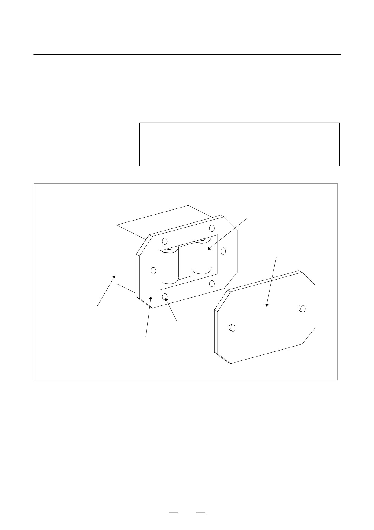
1) Prepare two alkaline dry cells (size D) commercially available.
commercial alkaline dry
2) Turn on the power to the Series 16i/18i/160i/180i.
cells (size D)
3) Remove the battery case cover.
4) Replace the cells, paying careful attention to their orientation.
5) Reinstall the cover onto the battery case.
CAUTION
When replacing the alkaline dry cells while the power is off,
use the same procedure as that for lithium battery
replacement described above.
Alkaline dry cell
2
Cover
Connection terminal on the rear
Mounting hole
4
Battery case
1134
B-63534EN/02
MAINTENANCE
1. METHOD OF REPLACING BATTERY
1.2
REPLACING THE
BATTERY FOR
STAND-ALONE TYPE
i SERIES
D Replacing the battery
If a lithium battery is used, have A02B-0200-K102 (FANUC internal
code: A98L-0031-0012) handy.
(1) Turn the CNC on. About 30 seconds later, turn the CNC off.
(2) Remove the battery from the top area of the CNC unit.
Disconnect the connector first. Then, remove the battery from the
battery case.
The battery case is provided in the top area of the face plate of the main
CPU board.
(3) Replace the battery, then connect the connector.
Battery case
Lithium battery
A02B-0200-K102
Connector
WARNING
The incorrect mounting of the battery may cause an
explosion. Avoid using any battery other than the one
specified here (A02B-0200-K102).
1135
1. METHOD OF REPLACING BATTERY
MAINTENANCE
B-63534EN/02
CAUTION
Complete steps (1) to (3) within 30 minutes.
If the battery is left removed for a long time, the memory
would lose the contents.
If there is a danger that the replacement cannot be
completed within 30 minutes, save the whole contents of the
CMOS memory to a memory card. The contents of the
memory can be easily restored with the memory card in
case the memory loses the contents.
Discard the dead battery, observing appropriate municipal rules and
regulations. When discarding the battery, insulate the terminal with a tape
so that no short-circuit would occur.
1136
B-63534EN/02
MAINTENANCE
1. METHOD OF REPLACING BATTERY
When using commercial
D-size alkaline dry cells
D Replacing the battery
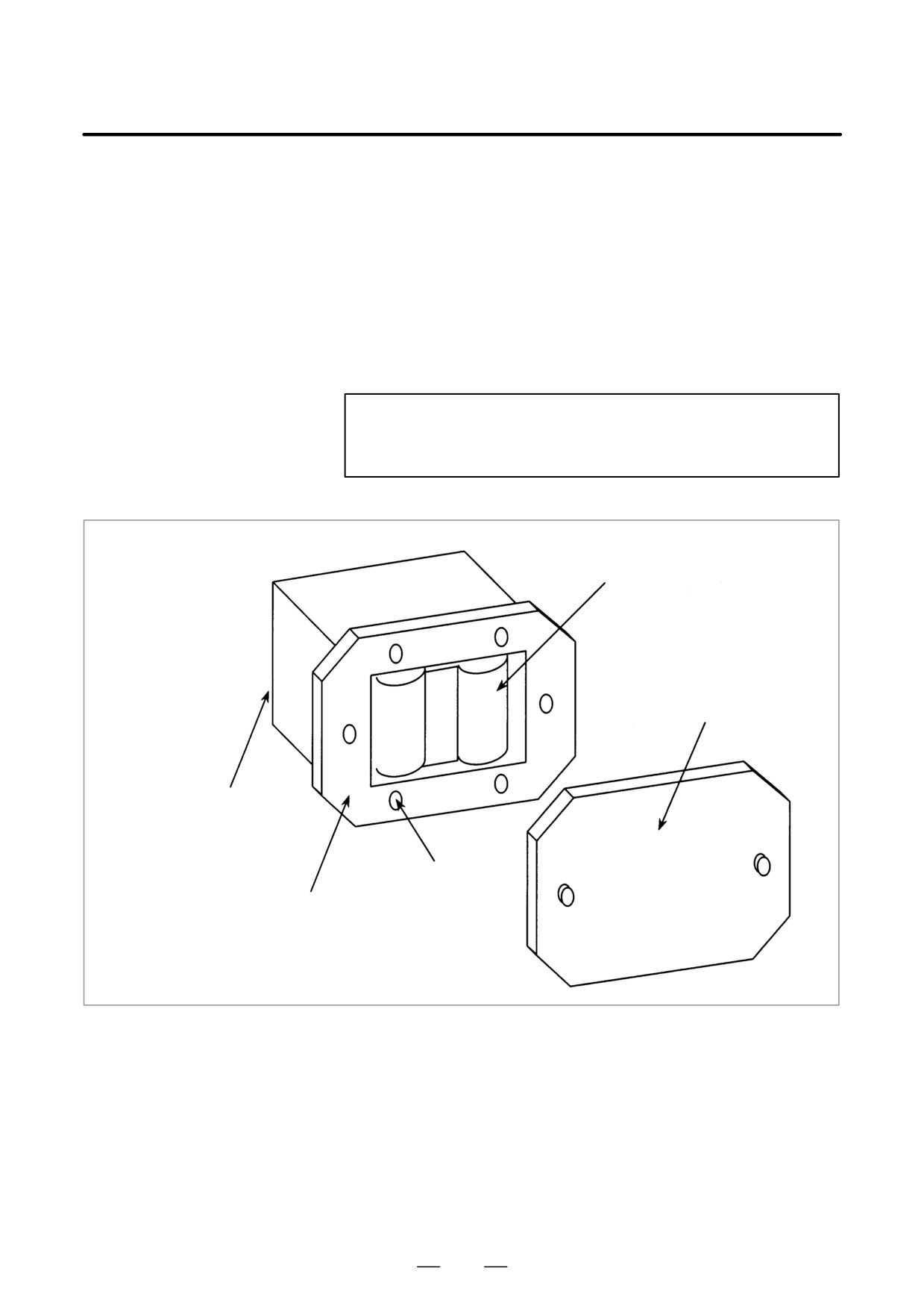
(1) Have commercial D-size alkaline dry cells handy.
(2) Turn the CNC on.
(3) Remove the lid from the battery case.
(4) Replace the old dry cells with new ones. Mount the dry cells in a
correct orientation.
(5) Replace the lid on the battery case.
CAUTION
In the power-off state, the battery should be replaced as in
the case of the lithium battery, which is descried above.
2 dry cells
Lid
Connection terminal
on the back
4 mounting holes
Case
1137
1. METHOD OF REPLACING BATTERY
MAINTENANCE
B-63534EN/02
1.3
A lithium battery is used to back up BIOS data in the CNC display unit
with PC functions. This battery is factory-set in the CNC display unit
BATTERY IN THE
with PC functions. This battery has sufficient capacity to retain BIOS
CNC DISPLAY UNIT
data for one year.
WITH PC FUNCTIONS
When the battery voltage becomes low, the LCD screen blinks. (The LCD
(3 VDC)
screen also blinks if a fan alarm is issued.) If the screen blinks, replace
the battery as soon as possible (within one week). FANUC recommends
that the battery be replaced once per year regardless of whether a battery
alarm is issued.
Replacing the battery
(1) To guard against the possible loss or destruction of BIOS parameters,
write down the BIOS parameter values.
(2) Obtain a new lithium battery (A02B-0200-K102).
(3) After power has been supplied for at least five seconds, turn off the
power to CNC display unit with PC functions. Remove the intelligent
terminal from the panel so that replacement work can be done from the
rear of the intelligent terminal.
(4) Detach the connector of the lithium battery, and remove the battery
from the battery holder.
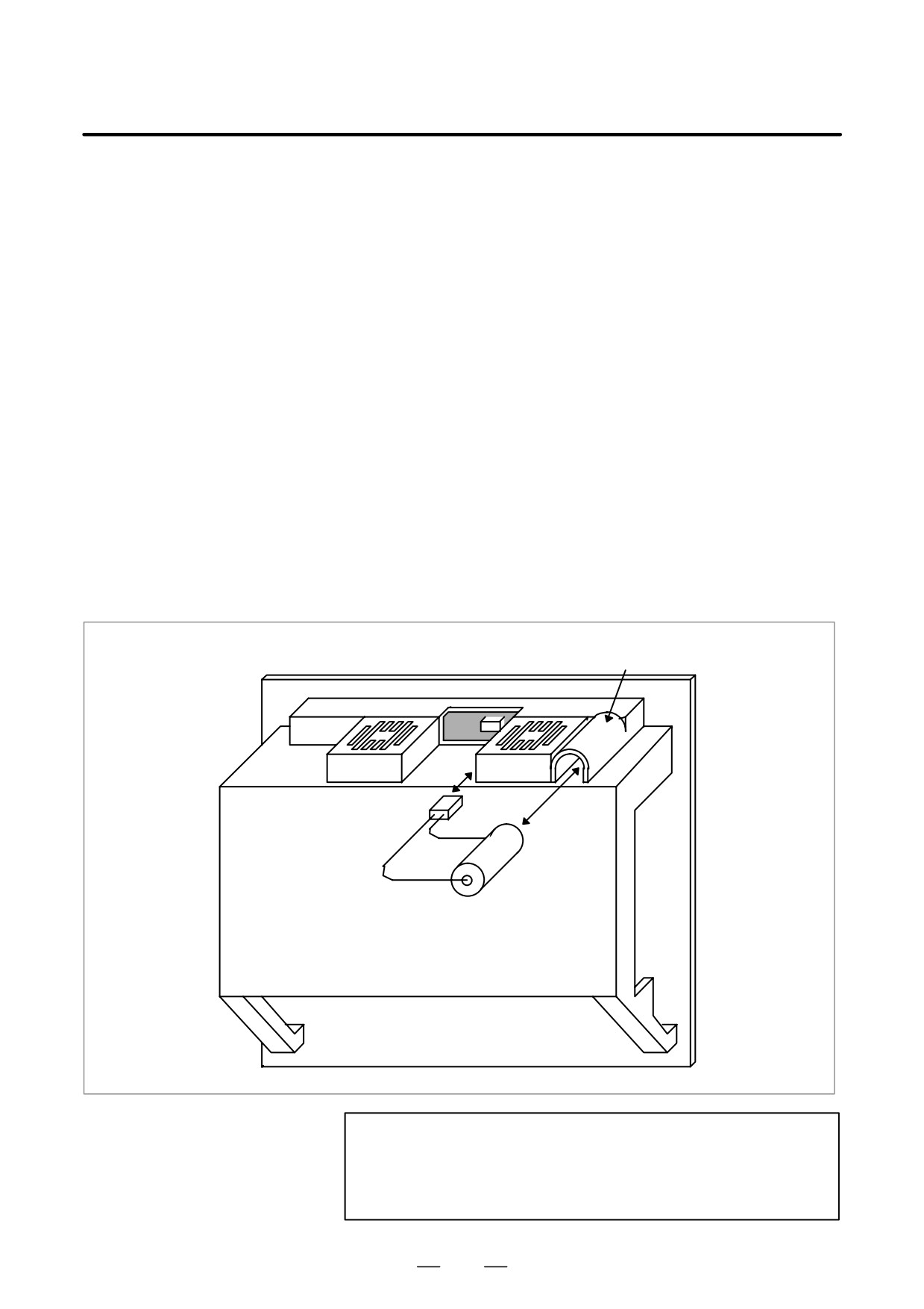
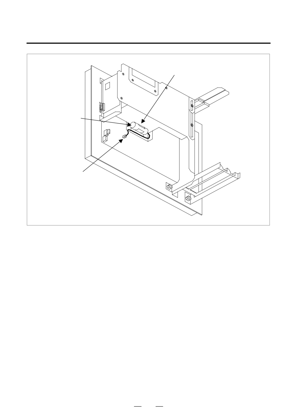
(5) Run the cable for the new lithium battery as shown in the Fig. 1.3.
(6) Attach the connector, and place the battery in the battery holder.
(7) Install CNC display unit with PC functions again.
(8) Turn on the power, and check that the BIOS parameters are maintained
(BIOS setup is not activated forcibly).
Between removing an old battery and inserting new battery, no more than
five minutes must be allowed to elapse.
1138
B-63534EN/02
MAINTENANCE
1. METHOD OF REPLACING BATTERY
Battery holder
Lithium battery
A02B-0200-K102
Connector
(BAT1)
Fig. 1.3 Lithium battery connection for CNC display unit with PC functions
1139
1. METHOD OF REPLACING BATTERY
MAINTENANCE
B-63534EN/02
1.4
One battery unit can maintain current position data for six absolute pulse
coders for a year.
BATTERY FOR
When the voltage of the battery becomes low, APC alarms 306 to 308 (+
SEPARATE
axis name) are displayed on the CRT display. When APC alarm 3n7 is
ABSOLUTE PULSE
displayed, replace the battery as soon as possible. In general, the battery
should be replaced within two or three weeks, however, this depends on
CODERS (6 VDC)
the number of pulse coders used.
If the voltage of the battery becomes any lower, the current positions for
the pulse coders can no longer be maintained. Turning on the power to
the control unit in this state causes APC alarm 300 (reference position
return request alarm) to occur. Return the tool to the reference position
after replacing the battery.
See Section 7.1.3 for details of connecting the battery to separate absolute
pulse coders. The battery for the built-in absolute pulse coder is installed
in the servo amplifier. For an explanation of the replacement procedure,
refer to the FANUC SERVO MOTOR a Series Maintenance Manual.
Replacing batteries
Obtain four commercially available alkaline batteries (size D).
(1) Turn on the power to the machine (i Series CNC).
(2) Loosen the screws on the battery case connected to the interface unit
of the detector separately installed, and remove the cover.
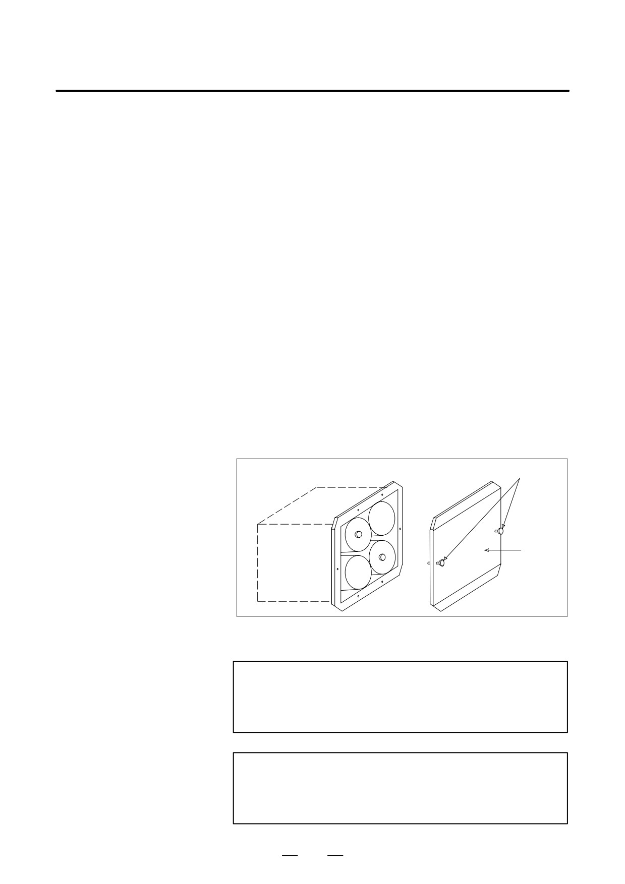
(3) Replace the dry batteries in the case.
Note the polarity of the batteries as shown in the figure below (orient
two batteries one way and the other two in the opposite direction).
Screws
Å
Å
Å
ÇÅ
ÇÇ
Cover
Å
Å
Å
Ç
ÅÅ
(4) After installing the new batteries, replace the cover.
(5) Turn off the power to the machine (i Series CNC).
WARNING
If the batteries are installed incorrectly, an explosion may
occur. Never use batteries other than the specified type
(Size D alkaline batteries).
CAUTION
Replace batteries while the power to the i Series CNC is on.
Note that, if batteries are replaced while no power is
supplied to the CNC, the recorded absolute position is lost.
1140
B-63534EN/02
MAINTENANCE
1. METHOD OF REPLACING BATTERY
1.5
When the battery voltage falls, APC alarms 306 to 308 are displayed on
the screen. When APC alarm 307 is displayed, replace the battery as soon
BATTERY FOR
as possible. In general, the battery should be replaced within one or two
BUILT-IN ABSOLUTE
weeks of the alarm first appearing. This, however, depends on the number
PULSE CODERS
of pulse coders being used.
If the battery voltage drops any further, the current positions for the pulse
(DC6V)
coders will be lost. Turning on the power to the control unit in this state.
(1) APC alarm 306 (battery zero alarm) and APC alarm 300 (reference
position return request alarm) occur. Return the tool to the reference
position after replacing the battery.
(2) The battery for the built-in absolute pulse coder is connected with the
servo amplifier.
(3) Note that the attachment methods of the battery and ordering
specifications of battery are different from SERVO AMPLIFIER ai
series (SVM) to SERVO AMPLIFIER b series.
1.5.1
The battery unit for the absolute pulse coder can be connected using
[Connection scheme 1] and [Connection scheme 2] explained below.
Method of Replacing
Refer to Subsection 9.3.2.6, “Battery” in “FANUC SERVO AMPLIFIER
Battery for Servo
ai series Descriptions (B-63282EN)” for details.
Amplifier ai series
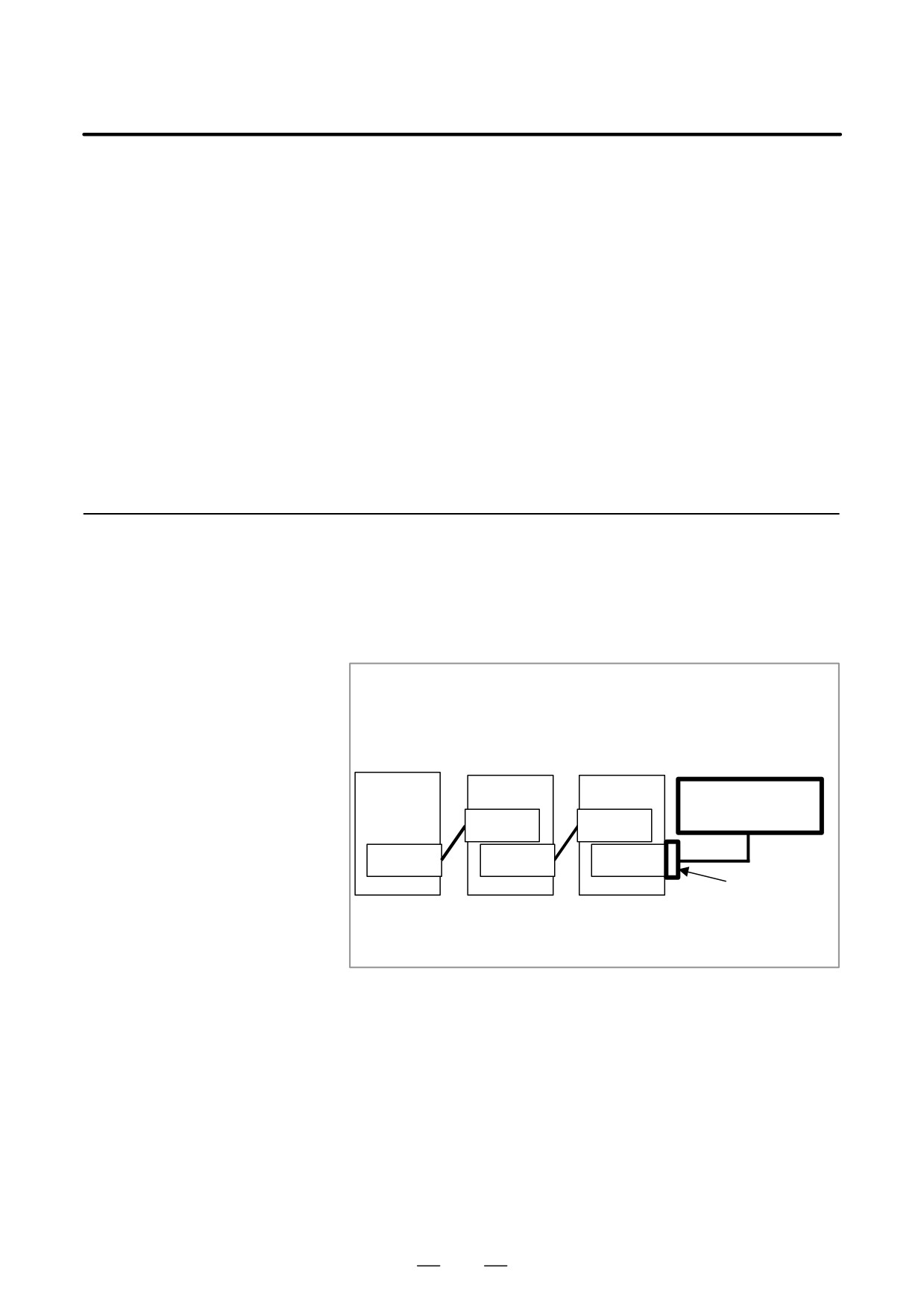
[Connection scheme 1]
Supplying power from
one battery unit to more
than one SVM
Battery case
A06B-6050-K060
PSM
SVM
SVM
Battery
A06B-6050-K061
CXA2B
CXA2B
CXA2A
CXA2A
CXA2A
Connector
A06B-6110-K211
- If a low battery voltage or a battery voltage of 0 V is indicated by an
APC (absolute pulse coder) alarm, replace the battery.
If a battery voltage of 0 V is indicated, you need to make a zero point
return.
- The absolute pulse coder of the ai series servo motor is incorporated
with a backup capacitor as standard. This backup capacitor enables an
absolute position detection to be continued for about 10 minutes.
Therefore, no zero point return need be performed if the time during
which servo amplifier power is kept off for battery replacement is
within 10 minutes.
- When the replacing of the battery takes more than 10 minutes, replace
the battery after see Item [Caution No.1 for battery replacement].
1141
1. METHOD OF REPLACING BATTERY
MAINTENANCE
B-63534EN/02
– The service life of the batteries is about two years if they are used in
a six-axis configuration with ai series servo motors and one year if
they are used in a six-axis configuration with a series servo motors.
FANUC recommends that you replace the batteries periodically
according to the battery service life.
- The battery unit consists of four R20 alkaline batteries. Commercial
batteries can be used in the battery unit. The optional battery offered
by FANUC is A06B-6050-K061.
WARNING
1
Do not connect more than one battery to the same BATL
(B3) line. If the output voltage is different between the
batteries, they may be short-circuited, resulting in the
batteries becoming very hot.
2
Install the battery with correct polarity. If the battery is
installed with incorrect polarity, it may overheat, blow out, or
catch fire.
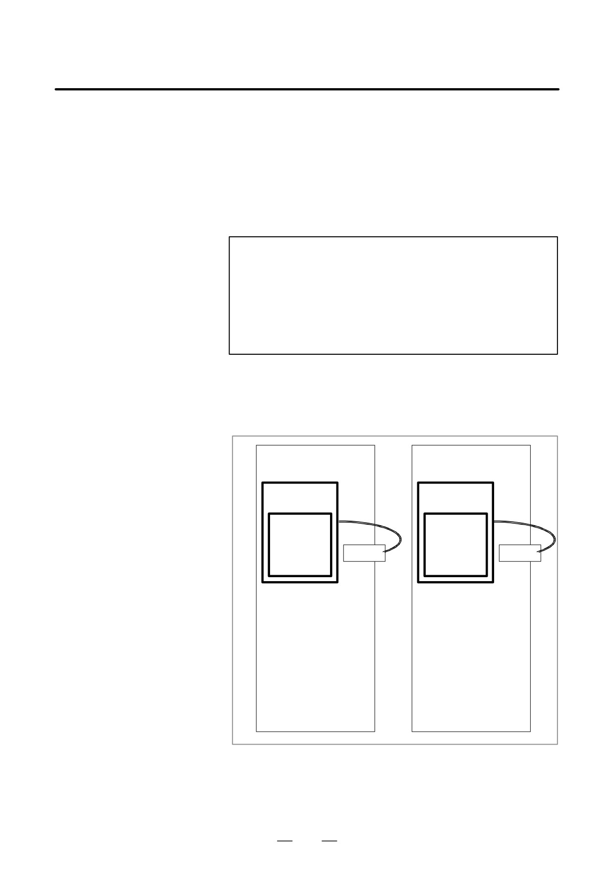
[Connection scheme 2]
Incorporating each SVM
with batteries
SVM
SVM
Battery case
Battery case
A06B-6114-K500
A06B-6114-K500
Battery
Battery
A06B-6073-K001
A06B-6073-K001
CX5X
CX5X
– If a low battery voltage or a battery voltage of 0 V is indicated by an APC
(absolute pulse coder) alarm, replace the battery(A06B-6073-K001).
If a battery voltage of 0 V is indicated, you need to make a zero point
return.
1142
B-63534EN/02
MAINTENANCE
1. METHOD OF REPLACING BATTERY
– The absolute pulse coder of the ai series servo motor is incorporated
with a backup capacitor as standard. This backup capacitor enables an
absolute position detection to be continued for about 10 minutes.
Therefore, no zero point return need be performed if the time during
which servo amplifier power is kept off for battery replacement is
within 10 minutes.
On the contrary, the absolute pulse coder of the standard a series servo
motor is not incorporated with a backup capacitor. Be careful when
replacing the battery for this pulse coder. See [Caution No.1 for battery
replacement] at the end of this section for details.
- The service life of the batteries is about two years with ai series servo
motors and one year with a series servo motors.
FANUC recommends that you replace the batteries periodically
according to the battery service life.
- The built-in batteries are not commercially available. They must be
purchased from FANUC. So, FANUC recommends that you keep
spares.
WARNING
1
When using the built-in batteries (A06B-6073-K001), do
not connect them to the BATL (B3) of connector CXA2A/
CXA2B.
The output voltages from different SVM batteries may be
short-circuited, resulting in the batteries becoming very hot.
2
Do not connect more than one battery to the same BATL
(B3) line. If the output voltage is different between the
batteries, they may be short-circuited, resulting in the
batteries becoming very hot.
3
Install the battery with correct polarity. If the battery is
installed with incorrect polarity, it may overheat, blow out, or
catch fire.
1143
1. METHOD OF REPLACING BATTERY
MAINTENANCE
B-63534EN/02
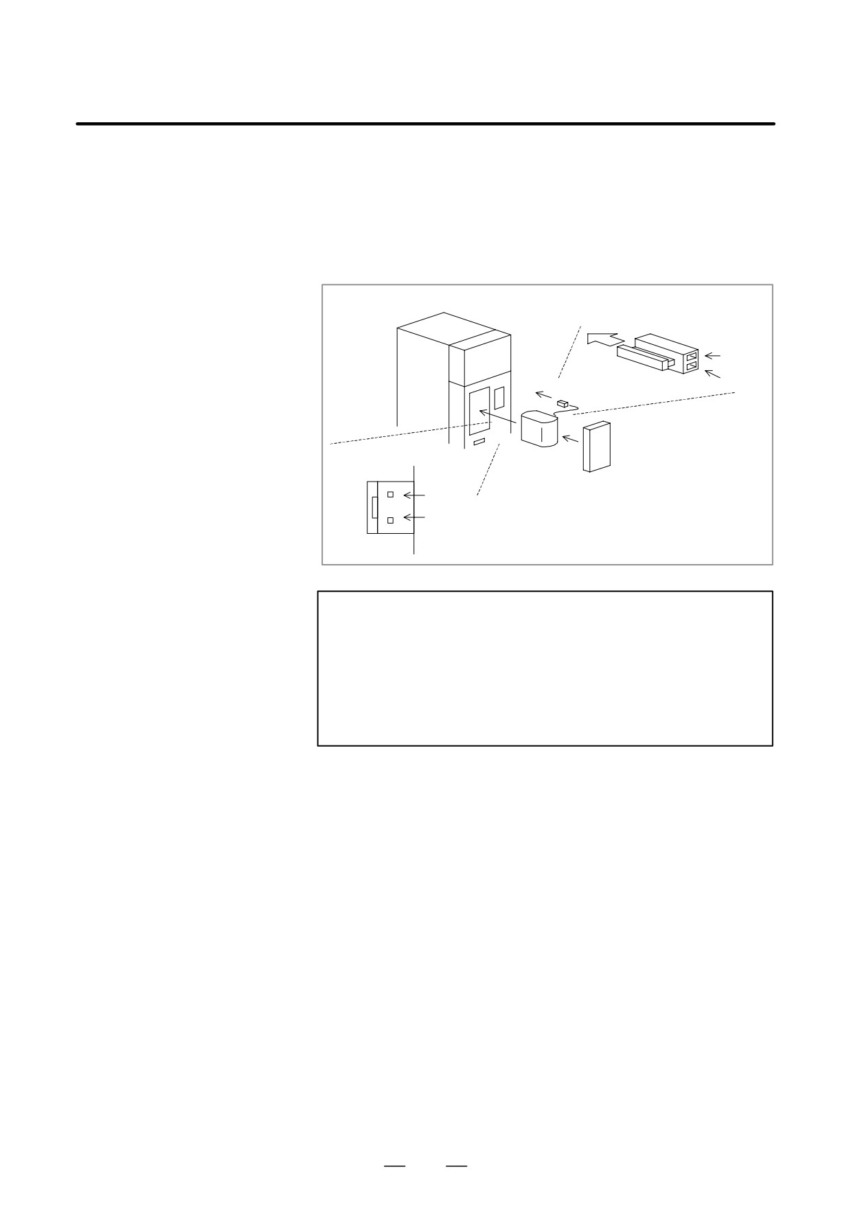
[Installation procedure for the battery]
(1) Remove the battery cover from the SVM.
(2) Install the battery in the SVM as shown in the figure below.
(3) Install the battery cover.
(4) Attach the battery connector to CX5X of the SVM.
SVM
Inserting direction
Cable side
Red: +6V
Connector
Black:
0V
Battery
CX5X
Battery cover
+6 V
0 V
CAUTION
1
When the battery is installed in the SVM from the side from
which the cable is drawn, the cable may be stretched tight,
which can lead to a poor contact condition. Therefore, install
the battery so that the cable is not extended tightly.
2
Be careful when handling the connector. See [Caution No.2
for battery replacement] at the end of this section for details.
[Caution No.1 for battery
The pulse coder for the a series servo motor is not incorporated with a
replacement]
backup capacitor as standard. To keep the absolute position information
in the absolute pulse coder, you need to keep the control power turned on
during battery replacement. Follow the procedure explained below.
[Replacing procedure for the battery]
1. Make sure that the power to the SVM is on (the 7-segment LED on
the front of the SVM is on).
2. Make sure that the emergency stop button of the system has been
pressed.
3. Make sure that the motor is not activated.
4. Make sure that the DC link charge LED of the SVM is off.
5. Remove the old battery, and install a new battery.
6. This completes the replacement. You can turn off the power to the
system.
1144
B-63534EN/02
MAINTENANCE
1. METHOD OF REPLACING BATTERY
WARNING
1
When replacing the battery, be careful not to touch bare
metal parts in the panel. In particular, be careful not to touch
any high-voltage circuits due to the electric shock hazard.
2
Before replacing the battery, check that the DC link charge
confirmation LED on the front of the servo amplifier is off.
Neglecting this check creates an electric shock hazard.
3
Install the battery with correct polarity. If the battery is
installed with incorrect polarity, it may overheat, blow out, or
catch fire.
4
Avoid a short-circuit between the +6V and 0V lines of a
battery or cable. A short-circuit may lead to a hot battery, an
explosion, or fire.
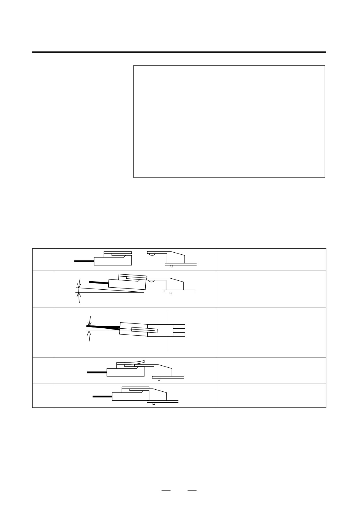
[Caution No.2 for battery
If an excessive strain is applied to a connector when it is inserted or
replacement]
removed, a poor contact may result. When inserting and removing the
battery connector, therefore, be careful not to apply an excessive
wrenching force to it; just follow the instructions given in the following
table.
(1) Attaching connectors
Check the attachment position.
<1>
Plug the cable connector while raising it
slightly.
<2>
10 degrees or less
Here, the angle of the cable connector to
the horizontal must be 5 degrees or less.
<5>
5 degrees or less
After passing the lock pin, insert the
<3>
connector straight.
The attachment of the connector is
<4>
completed.
1145
1. METHOD OF REPLACING BATTERY
MAINTENANCE
B-63534EN/02
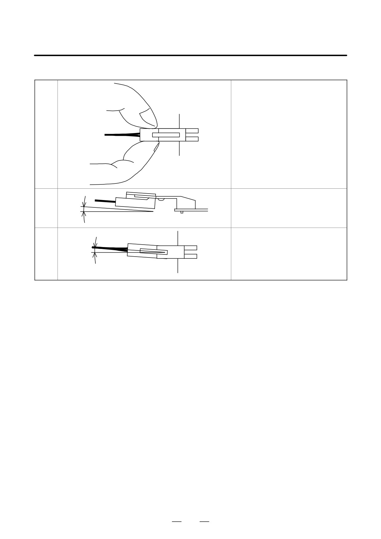
(2) Detaching the connector
Hold both the sides of the cable insulator
and the cable, and pull them horizontally.
<1>
Pull out the cable side while raising it
slightly.
<2>
10 degrees or less
Here, the angle of the cable to the
horizontal must be 5 degrees or less.
<3>
5 degrees or less
1146
B-63534EN/02
MAINTENANCE
1. METHOD OF REPLACING BATTERY
1.5.2
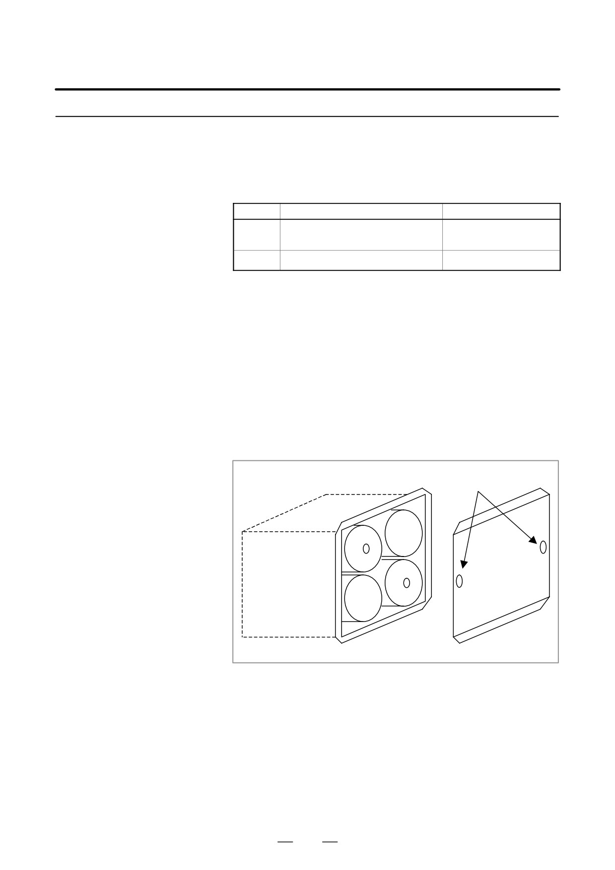
The battery is connected in either of 2 ways as follows.
Method of Replacing
Method 1: Use the battery case (A06B-6050-K060).
Battery for Servo
Use the battery: A06B-6050-K061 or D-size alkaline battery.
Amplifier b series
Method 2: Attach the lithium battery to the SVM.
Use the battery: A06B-6093-K001.
Method
Item
Ordering specification
Method 1
Battery (4 pieces of D-size alkaline
A06B-6050-K061
battery)
Method 2
Battery (Lithium battery)
A06B-6093-K001
D Replacement of batteries in the battery case. (Method 1)
Replace four D-size alkaline batteries in the battery case installed in
the machine.
[Attachment procedure]
(1) Turn the servo unit (machine) on.
(2) Place the machine in the emergency stop state.
(3) Confirm that the servo motors are not active.
(4) Have four D-size alkaline batteries on hand.
(5) Loosen the screws on the battery case. Remove the cover.
(6) Replace the alkaline batteries in the case. Pay careful attention
to the polarity of the alkaline batteries.
(7) Attach the cover.
Screws
Cover
D Attach the lithium battery to the amplifier. (Method 2)
Attach the lithium (A06B-6093-K001) battery to the amplifier.
[Attachment procedure]
(1) Turn the servo unit (machine) on.
(2) Place the machine in the emergency stop state.
(3) Confirm that the servo motors are not active.
(4) In case of SVU-12 or SVU-20, remove the battery cover under
the servo unit grasping its left and right sides. In case of
SVU-40 or SVU-80, remove the cover attached on right side
of the servo unit grasping its upper and lower sides.
1147
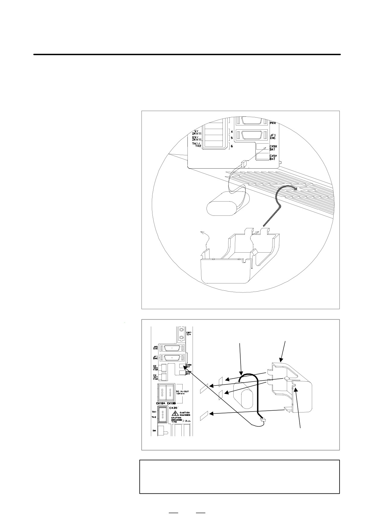
1. METHOD OF REPLACING BATTERY
MAINTENANCE
B-63534EN/02
(5) Remove the battery from the servo unit.
(6) Replace the battery and connect the battery cable with the
connector CX5X or CX5Y of the servo unit.
(7) Mount the battery cover.
SVU-12, SVU-20
Battery cover
Battery
Pass the battery cable to this slit.
SVU-40, SVU-80
CAUTIONS
D The connector of the battery can be connected with either
of CX5X and CX5Y.
1148
B-63534EN/02
MAINTENANCE
1. METHOD OF REPLACING BATTERY
Used batteries
Old batteries should be disposed as
“INDUSTRIAL WASTES”
according to the regulations of the country or autonomy where your
machine has been installed.
1149