FANUC Series 16i/160i/160is-MB, Series 18i/180i/180is-MB5, Series 18i/180i/180is-MB. Operator's Manual - page 38
12. GRAPHICS FUNCTION
OPERATION
B-63534EN/02
GRAPHICS FUNCTION
12
Two graphic functions are available. One is a graphic display function,
and the other is a dynamic graphic display function.
The graphic display function can draw the tool path specified by a
program being executed on a screen. The graphic display function also
allows enlargement and reduction of the display.
The dynamic graphic display function can draw a tool path and machining
profile.
In tool path drawing, automatic scaling and solid drawing are possible.
In machining profile drawing, the status of machining in progress can be
drawn through simulation. Blank figures can also be drawn.
The background drawing function enables drawing to be performed by
one program while machining is performed by another program.
This chapter mainly explains drawing procedures and drawing
parameters for the following:
1. Drawing the tool path specified by a program being executed, with the
graphic display function
2. Drawing the tool path with the dynamic graphic display function
3. Drawing the machining profile with the dynamic graphic display
function
4. Background drawing procedure
1090
B-63534EN/02
OPERATION
12. GRAPHICS FUNCTION
It is possible to draw the programmed tool path on the screen, which
12.1
makes it possible to check the progress of machining, while observing the
GRAPHICS DISPLAY
path on the screen.
In addition, it is also possible to enlarge/reduce the screen.
Before drawing, graphic parameters must be set.
When the dynamic graphics function is used, the graphics function
described in this section cannot be used. See Section 12.2 for the dynamic
graphics function.
Graphics display procedure
Procedure
CUSTOM
1
Press function key
GRAPH
. Press
for a small MDI unit.
GRAPH
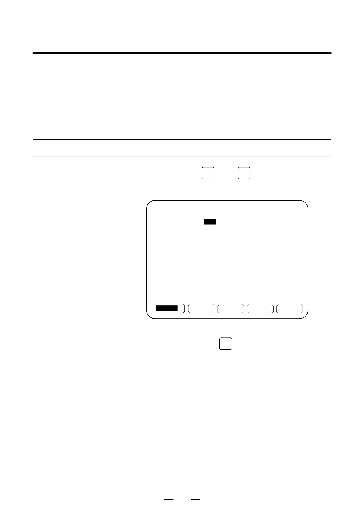
The graphic parameter screen shown below appears. (If this screen
does not appear, press soft key [PARAM].)
GRAPHIC PARAMETER
O0000 N00000
AXES
P=
4
(XY=0.YZ=1,ZY=2, XZ=3, XYZ=4, ZXY=5)
RANGE
(MAX.)
X=
115000
Y=
150000
Z=
0
RANGE
(MIN.)
X=
0
Y=
0
Z=
0
SCALE
K=
70
GRAPHIC CENTER
X=
57500
Y=
75000
Z=
0
PROGRAM STOP
N=
0
AUTO ERASE
A=
1
MDI
****
***
***
14 : 23 : 54
PARAM
GRAPH
2
Move the cursor with the cursor keys to a parameter to set.
3
Enter data, then press the
INPUT
key.
4
Repeat steps 2 and 3 until all required parameters are specified.
5
Press soft key [GRAPH].
1091

12. GRAPHICS FUNCTION
OPERATION
B-63534EN/02
6
Automatic operation is started and machine movement is drawn on
the screen.
0001
00012
X
0.000
Y
0.000
Z
0.000
Z
X
Y
S 0T
MEM * * * *
***
***
14 : 23 : 03
PARAM
GRAPH
Explanation
D RANGE
The size of the graphic screen will be as follows:
(Actual graphic range)
Gc : Center of the screen
72mm
45(75)mm
(120)
Gc
72mm
45(75)mm
(120)
Note : ( ) indicate the values for 9.5”/10.4” LCD.
Fig. 12.1 (a) Graphic range
As shown in Fig.12.1 (a), the maximum graphics range is an area of
approx. 144 mm (width) × 90 mm (height) for 7.2″/8.4″ LCD and approx.
240 mm (width) ×150 mm (height) for 9.5″/10.4″ LCD.
D Setting the graphics
To draw a section of the program within the actual graphics range, set the
range
graphics range using one of the following two methods:
1 . Set the center coordinates of the range and the magnification.
2 . Set the maximum and minimum coordinates for the range in the
program.
Whether 1 or 2 is used depends on which parameters are set last. A
graphics range which has been set is retained when the power is turned
off.
1092
B-63534EN/02
OPERATION
12. GRAPHICS FUNCTION
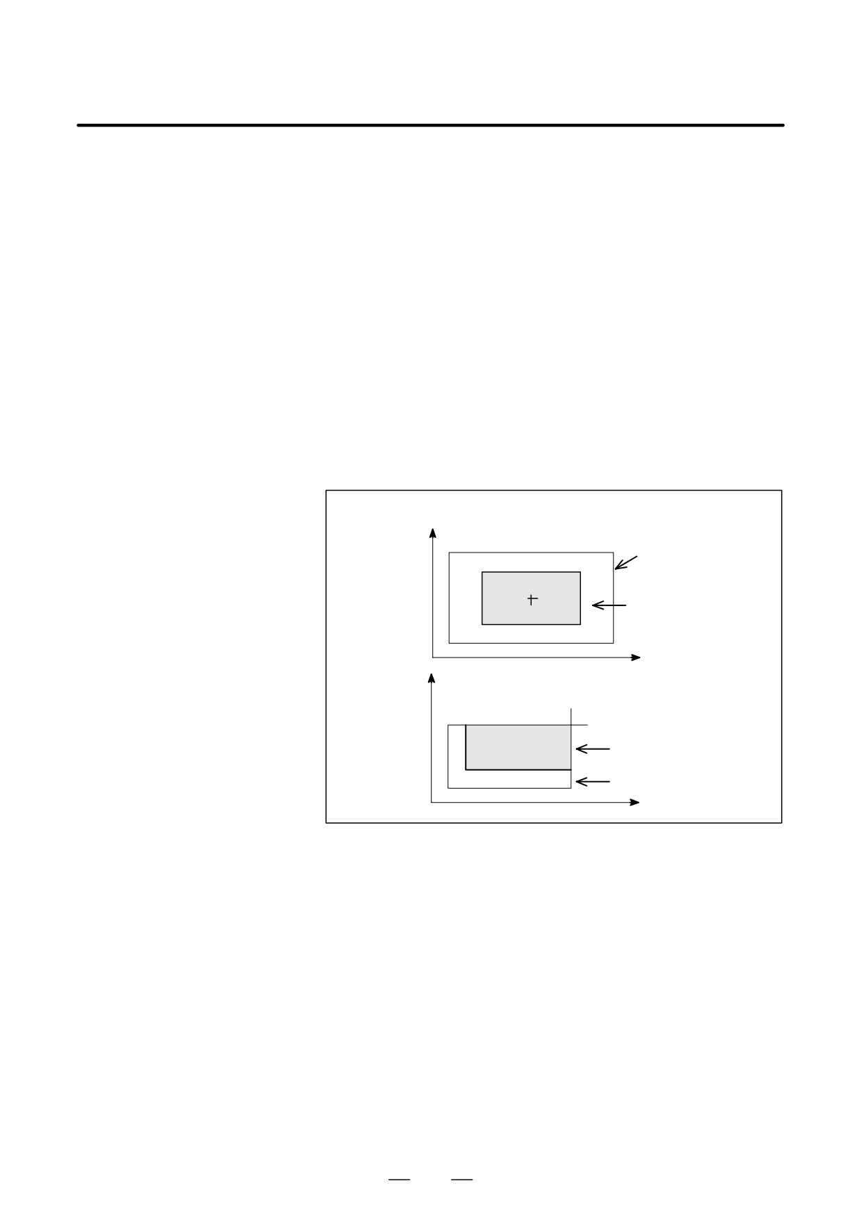
1. Setting the center
Set the center of the graphic range to the center of the screen. If the
coordinate of the
drawing range in the program can be contained in the above actual
graphics range and
graphics range, set the magnification to 1 (actual value set is 100).
graphics magnification
When the drawing range is larger than the maximum graphics range or
much smaller than the maximum graphics range, the graphics
magnification should be changed. The graphics magnification is 0.01 to
100.00 times, which is usually determined as follows;
Graphics magnification=Graphics magnification (H), or graphics
magnifications (V), whichever is smaller
Graphics magnification H =α/(length on program to horizontal
direction axis)
Graphics magnification V=β/(length on program to vertical
direction axis)
α:144mm (for seven soft key type)
β:90mm (for twelve soft key type)
α:240mm (for seven soft key type)
β:150mm (for twelve soft key type)
The graphics magnification is always based on the center of the screen.
Graphics range after
Program
magnification is applied
Gc
Graphics range before
magnification is applied
Gc : Center of screen
Program
Gc
Graphics range before
magnification is applied
Graphics range after
magnification is applied
Fig. 12.1 (b) Applying graphics magnification (Example of enlargement)
1093
12. GRAPHICS FUNCTION
OPERATION
B-63534EN/02
2. Setting the maximum
When the actual tool path is not near the center of the screen, method 1
and minimum
will cause the tool path to be drawn out of the geaphics range if graphics
coordinates for the
magnification is not set properly.
drawing range in the
To avoid such cases, the following six graphic parameters are prepared;
program
Graphic range (Max.) X
Graphic range (Max.) Y
Graphic range (Max.) Z
Graphic range (Min.) X
Graphic range (Min.) Y
Graphic range (Min.) Z
With the above parameters, the center of screen (Gcx, Gcy, Gcz) is
determined by the CNC as follows;
Gcx = (X (MAX.) + X (MIN.) ) /2
Gcy = (Y (MAX.) + Y (MIN.) ) /2
Gcz = (Z (MAX.) + Z (MIN.) ) / 2
The unit of the value will be 0.001 mm or 0.0001 inch depending on the
input unit.
Graphics magnification is applied automatically. When the graphics
range is specified, the center coordinates and magnification do not need
to be calculated.
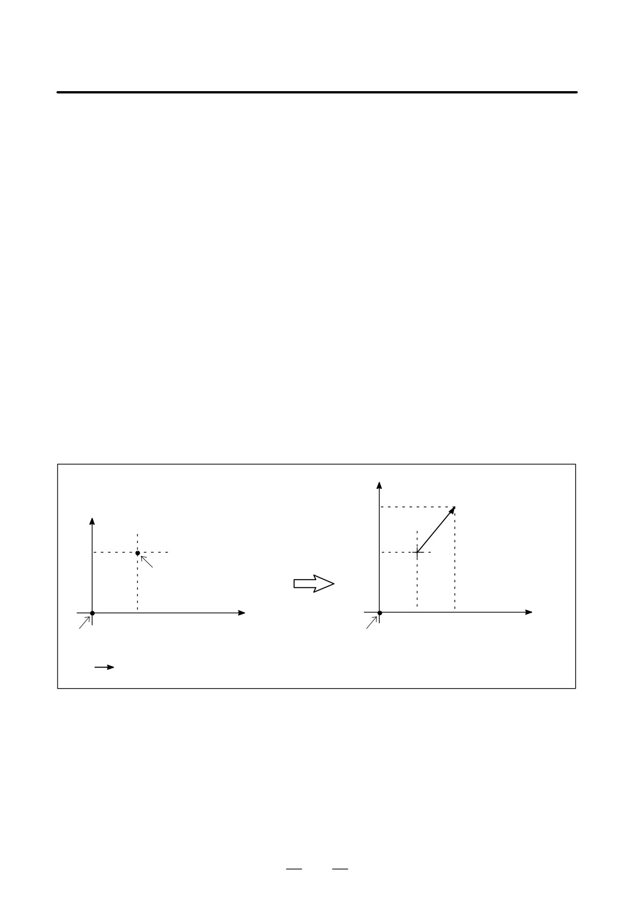
D Work coordinate system
The graphic origin and graphic center point will not be changed even if
and graphics
the workpiece coordinate origin is changed.
In other words, the workpiece coordinate origin is always consistent with
the graphic origin.
Y
(Example)
Graphics point (60mm, 90mm)
Y
Gc (=30mm, 50mm)
G92 X60. Y90. ;
Gc
After execution
Graphics point
X
X
Graphics origin
Graphics origin=workpiece coordinate origin
As shown in the above example, when the command of G92 is specified, the drawing is moved as indicated
by
. The position of the graphics origin or graphics center does not change.
Fig. 12.1 (c) Workpiece coordinate origin and graphics origin
1094
B-63534EN/02
OPERATION
12. GRAPHICS FUNCTION
D Graphics parameter
⋅
AXES
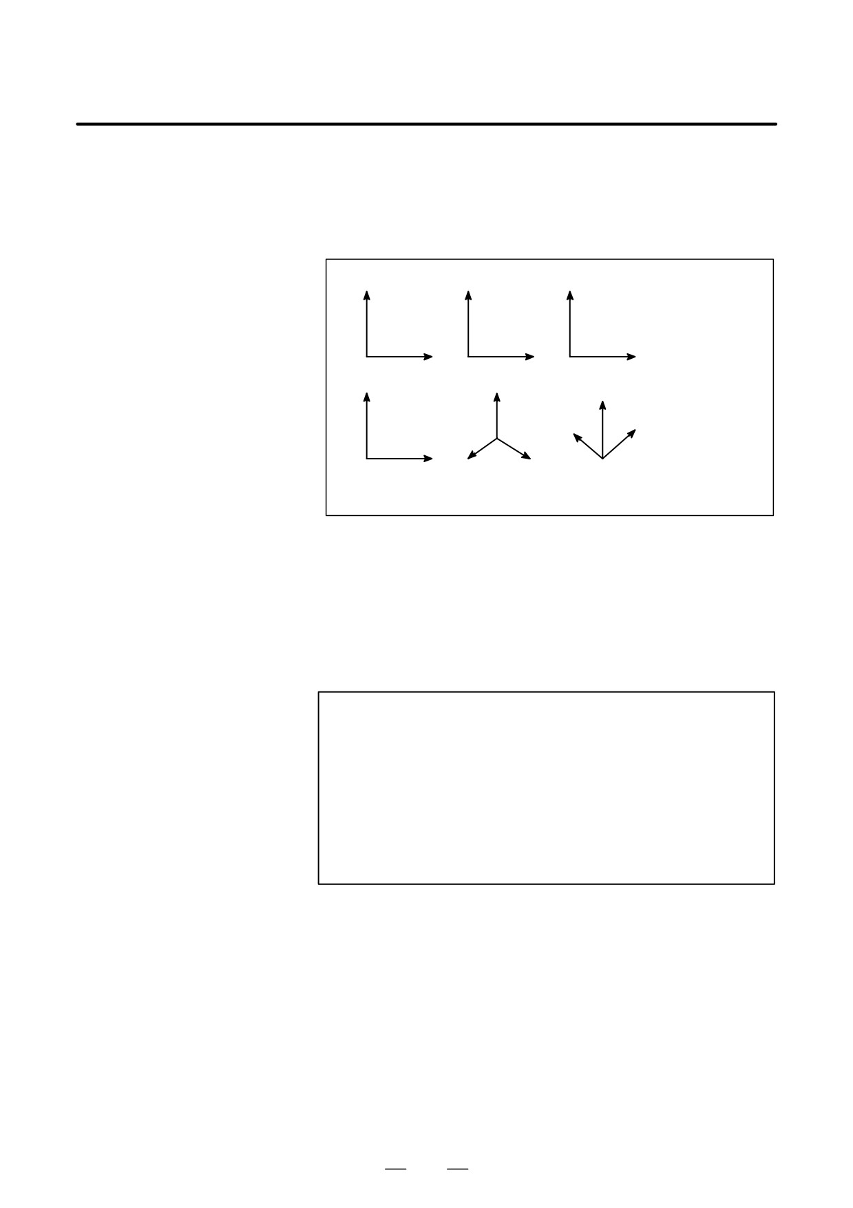
Specify the plane to use for drawing. The user can choose from the
following six coordinate systems.
With two-path control, a different drawing coordinate system can be
selected for each tool post.
Y
Z
Y
= 0 : Select (1)
= 1 : Select (2)
(1)
(2)
(3)
= 2 : Select (3)
= 3 : Select (4)
= 4 : Select (5)
X
Y
Z
= 5 : Select (6)
Z
Z
Y
(6)
(4)
(5)
Z
X
X
Y
X
The rotating angle (horizontal, vertical) for isometric display of 5) and 6) is
fixed at 45°in both cases.
Fig. 12.1 (d) Coordinate system
⋅
RANGE (Max., Min.)
Set the graphic range displayed on the screen by specifying maximum
and minimum values along each axis.
X=Maximum value X=Minimum value
Y=Maximum value Y=Minimum value
Z=Maximum value Z=Minimum value
Valid range: 0 to "9999999
NOTE
1
The units are 0.001 mm or 0.0001 inch. Note that the
maximum value must be greater than the minimum value for
each axis.
2
When setting the graphics range with the graphics
parameters for the maximum and minimum values, do not
set the parameters for the magnification and screen center
coordinates afterwards. Only the parameters set last are
effective.
⋅
SCALE
Set the graphic magnification
The setting range is 0 to 10000 (unit:0.01 time).
1095
12. GRAPHICS FUNCTION
OPERATION
B-63534EN/02
⋅
GRAPHIC CENTER
X=
Y=
Z=
Set the coordinate value on the workpiece coordinate system at
graphic center.
NOTE
1
When MAX. and MIN. of RANGE are set, the values will be
set automatically once drawing is executed
2
When setting the graphics range with the graphics
parameters for the magnification and screen center
coordinates, do not set the parameters for the maximum
and minimum values afterward. Only the parameters set
last are effective.
⋅
PROGRAM STOP
N=
Set the sequence No. of the end block when necessary to partially
display.
This value is automatically cancelled and set to -1 once drawing is
executed.
⋅
AUTO ERASE
1 : Erase the previous drawing automatically when the automatic
operation is started under reset condition.
2 : Not erase automatically.
D Executing drawing only
Since the graphic drawing is done when coordinate value is renewed
during automatic operation, etc., it is necessary to start the program by
automatic operation. To execute drawing without moving the machine,
therefore, enter the machine lock state.
D Deleting the previous
When the AUTO operation is started under reset condition, the program
drawing
is executed after deleting the previous drawing automatically (Automatic
deleting=1). It is possible not to delete the previous drawing by graphic
parameter (Automatic deleting=0).
D Drawing a part of a
When necessary to display a part of a program, search the starting block
program
to be drawn by the sequence No. search, and set the sequence No. of the
end block to the PROGRAM STOP N= of the graphic parameter before
starting the program under cycle operation mode.
D Drawing using dashed
The tool path is shown with a dashed line (
) for rapid traverse and
lines and solid lines
with a solid line (
) for cutting feed.
Limitations
D Feedrate
In case the feed rate is considerably high, drawing may not be executed
correctly, decrease the speed by dry-run, etc. to execute drawing.
D Two-path lathe control
For the two-path lathe control, two paths can not be displayed at the same
time.
1096

B-63534EN/02
OPERATION
12. GRAPHICS FUNCTION
There are the following two functions in Dynamic Graphics.
12.2
DYNAMIC GRAPHIC
This is used to draw the path of tool center com-
Path graphic
manded by the part program.
DISPLAY
This is used to draw the workpiece figure machined by
Solid graphic
tool movement commanded by the part program.
The path graphic function is used to precisely check the part program for
drawing the tool path with a line. The solid graphic function is used to
draw the workpiece figure to be machined with a program. Thus, it is easy
to recognize roughly the part program. These two functions can be used
freely by switching them.
12.2.1
The path graphic feature calls a program from memory and draws the tool
path specified by the program. This feature provides the following
Path Drawing
functions.
1. Drawing plane
The user can choose the drawing plane from four types of plane views,
two types of isometric projection views, and biplane view.
2. Drawing rotation
When an isometric projection view is used, the drawing can be rotated
horizontally and vertically.
3. Drawing enlargement
A drawing can be enlarged or reduced by specifying a magnification from
and reduction
0.01 to 100 with respect to the actual size. In addition, a drawing can be
automatically enlarged or reduced by setting maximum and minimum
values.
4. Partial drawing
A range of the program can be drawn by specifying a starting sequence
number and ending sequence number.
5. Programmed path
The user can specify whether to apply tool length offset and cutter
and tool path
compensation to drawing. This way, either the actual programmed path
drawing
or the tool path can be drawn.
6. Color
When a tool path is drawn on a screen, the colors used can be chosen from
seven colors including white. The color of the tool path can be changed
according to the T code.
7. Automatic scaling
The CNC automatically determines the maximum and minimum drawing
coordinates for each program. This means that drawing can be performed
with a magnification automatically determined according to these
maximum and minimum values.
8. Partial enlargement
Except for biplane views the user can enlarge all types of drawings by a
drawing
factor of up to 100 while looking at the drawing that has been made.
9. Indicating the current
The current tool position can be displayed on the screen.
tool position with a
mark
10. Indicating the
The current position can also be indicated using coordinates.
coordinates of the
current position
1097
12. GRAPHICS FUNCTION
OPERATION
B-63534EN/02
11. Displaying
Coordinate axes and actual size dimension lines are displayed together
coordinate axes and
with the drawing so that actual size can be referenced.
actual size
dimensions lines
The first six functions above (1. to 6.) are available by setting the graphic
parameters. The seventh to ninth functions (7. to 9.) are mainly executed
using soft keys after drawing has been setup. The tenth function (10.) is
enabled by setting a parameter. The eleventh function (11.) can be used
at any time.
Path drawing procedure
Procedure
1
To draw a tool path, necessary data must be set beforehand.
CUSTOM
So press the function button
GRAPH
some times (
for the small
GRAPH
MDI).The “PATH GRAPHIC (PARAMETER)” is displayed.
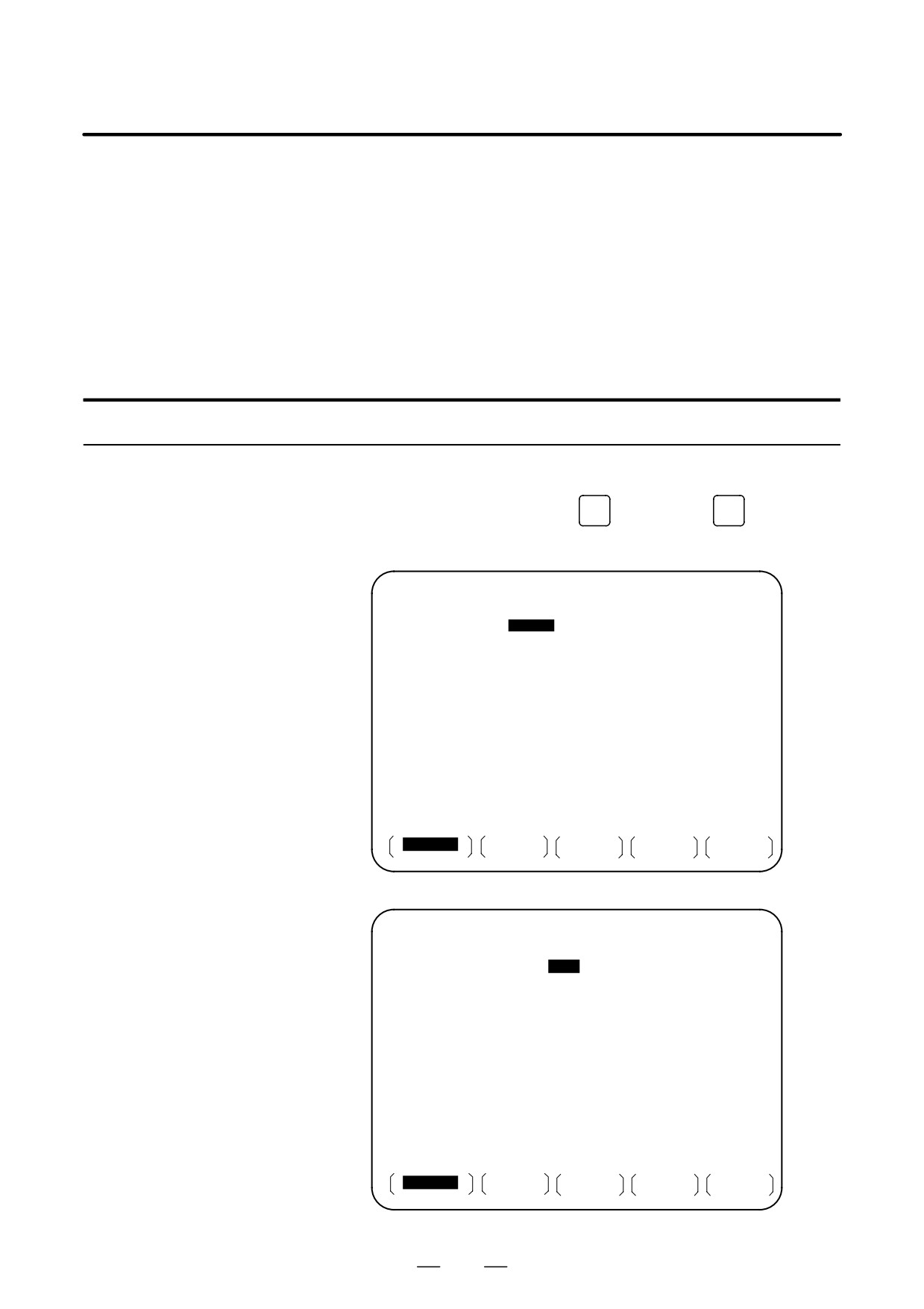
PATH GRAPHIC (PARAMETER-1)
O0000 N00002
AXES
P=
4
(XY=0, YZ=1, ZY=2, XZ=3, XYZ=4, ZXY=5, 2P=6)
ANGLE
ROTATION
A=
0
TILTING
A=
0
SCALE
K=
0.00
CENTER OR MAX./MIN.
X=130.000
Y=
110.000
Z= 50.000
I=
0.000
J=
-10.000
K=
0.000
START SEQ. NO. N=
0
END SEQ. NO.
N=
0
NO. A=
MDI
****
***
***
14 : 25 : 07
PARAM
EXEC
SCALE
POS
PATH GRAPHIC (PARAMETER-2) O0000 N00001
TOOL. COMP
P=
0
COLOR (0123456)
PATH
P=
0
TOOL
Q=
0
AUTO CHANGE
R=
0
MDI
****
***
***
14 : 25 : 51
PARAM
EXEC
SCALE
POS
1098
B-63534EN/02
OPERATION
12. GRAPHICS FUNCTION
2
There are two screens for setting drawing parameters.
Press the page key according to the setting items for selecting
screens.
3
Set the cursor to an item to be set by cursor keys.
4
Input numerics by numeric keys.
5
Press the
INPUT
key.
The input numerics are set by these operations and the cursor
automatically moves to the next setting items. The set data is held even
after the power is turned off.
6
Set the operation mode to the memory mode, press function key
PROG
, and call the part program which should be drawn.
GRAPH
CUSTOM
7
Press function key
(
GRAPH
for a small MDI) several times to
redisplay the PATH GRAPHIC (PARAMETER) screen, then press soft
key [EXEC] to display the PATH GRAPHIC (EXECUTION) screen.
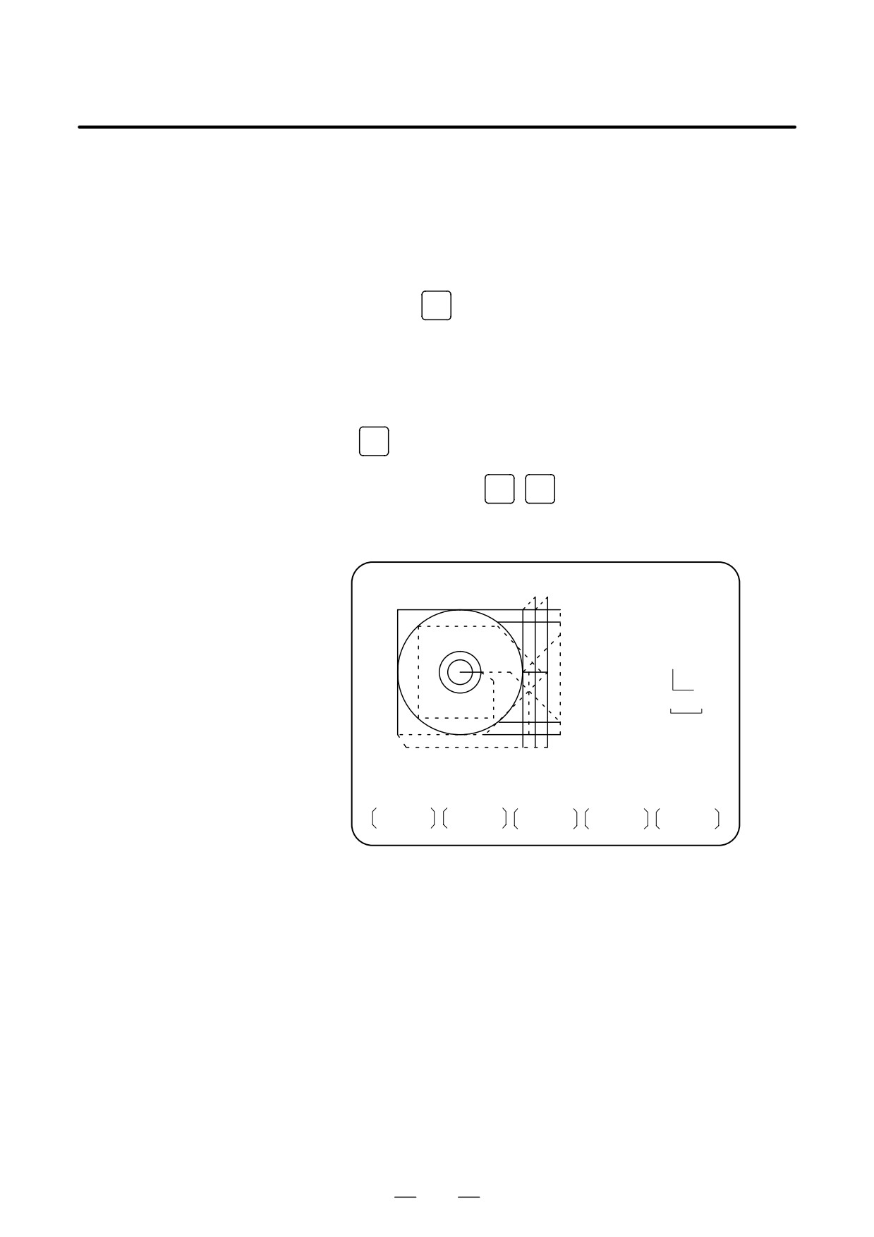
PATH GRAPHIC (EXECUTION)
O1126 N01126
Y
X
25.8
MEM * * * *
***
***
10 : 10 : 40
AUTO
START
STOP
REWIND
ERASE
8
Press soft key [(OPRT)], then press soft key [AUTO] or [START].
Pressing
[AUTO] enables automatic scaling. See item
7 in
introduction of path drawing and the description of soft key [AUTO]
in Explanations for details. Drawing is now started. During drawing,
the message ”DRAWING” blinks at the lower-right corner of the CRT
screen.
9
Press soft key [STOP] to pause drawing. The indication of “STOP”
blinks at the lower right corner on the CRT screen. Press soft key
[START] to start drawing. In addition, press soft key [REWIND] to
redraw from the top of program before pressing soft key [START].
10
Execute the last of part program (M02/M30) to end drawing. This
will cause, blinking of the “DRAWING” light to turn off. The tool
path view drawn can be retained until the power is turned off
unless a new tool path view is drawn.
1099
12. GRAPHICS FUNCTION
OPERATION
B-63534EN/02
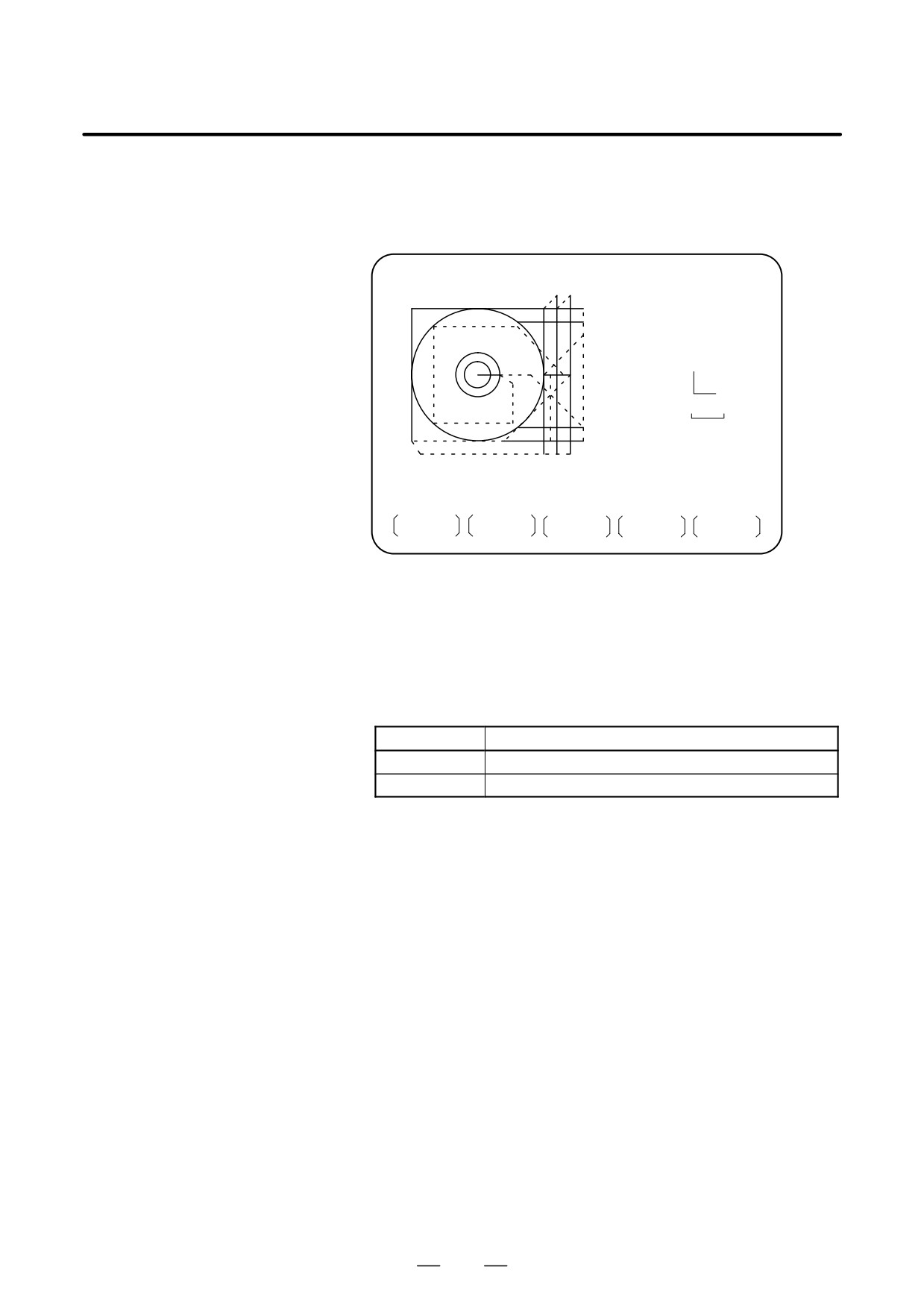
Partial enlargement
11
For partial drawing enlargement, display the PATH GRAPHIC
(SCALE) screen by pressing the soft key [ZOOM] on the PATH
GRAPHIC (PARAMETER) screen of step 1 above. The tool path is
displayed. Next, press soft key [(OPRT)].
PATH GRAPHIC (SCALE)
O1126 N01126
SCALE
1.00
Y
X
25.8
MEM * * * *
***
***
10 : 10 : 40
EXEC
←
→
↓
↑
12
Perform positioning of marks displayed at the center of the screen
to the center of the part enlarged using soft keys [←], [→], [↓],
and [↑].
13
Set the relative magnification rate for the tool path view which is
being drawn using the address keys “P” and “M”. When you press
address key P or M, the following results:
Address key
Function
P
The relative magnification rate increases by 0.1.
M
The relative magnification rate decreases by 0.1.
The relative magnification rate is continuously changed by keeping
the address keys depressed. It is possible to magnify up to 100
times in reference to the actual dimensions.
14
Press the soft key [EXEC] after setting the relative magnification
rate. Then, the screen automatically changes to “TOOL PATH
(EXECUTION)” and the drawing of set partial enlargement view
starts. The set partial enlargement status is valid until soft key
[AUTO] or [ERASE] is pressed.
1100
B-63534EN/02
OPERATION
12. GRAPHICS FUNCTION
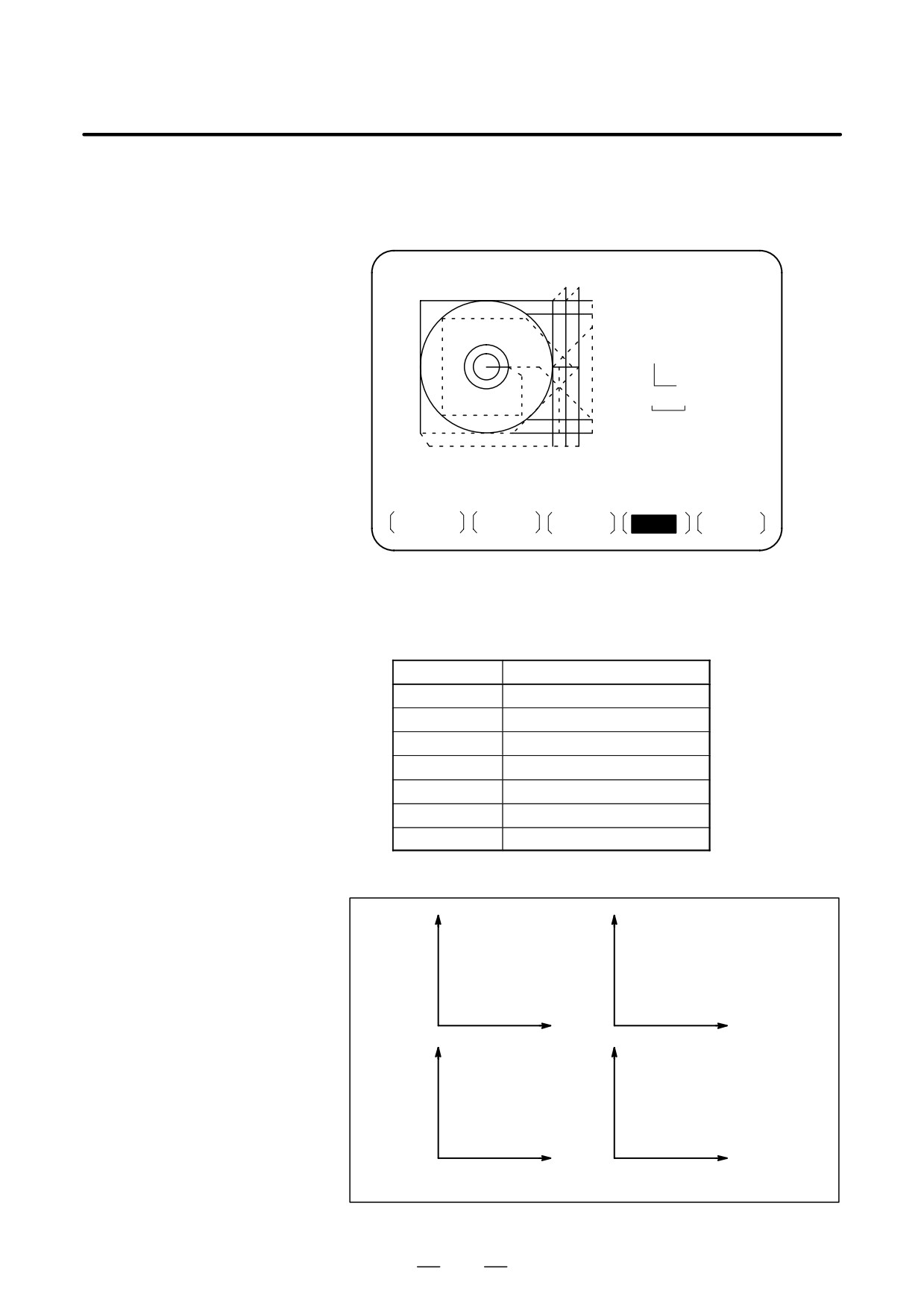
Mark display
15
To display a mark at the current tool position, display the PATH
GRAPHIC (POSITION) screen by pressing soft key [POS] on the
PATH GRAPHIC (PARAMETER) screen of step 1 above. This
mark blinks at the current tool center position on the tool path.
PATH GRAPHIC (POSITION)
O1126 N01126
Y
X
25.8
MDI
****
***
***
14 : 27 : 47
PARAM
EXEC
SCALE
POS
Explanations
D AXES
The relationship between the setting value and drawing screen is as shown
below:
Setting value
Drawing screen
0
Plane view (XY)
1
Plane view (YZ)
2
Plane view (ZY)
3
Plane view (XZ)
4
Isometric projection (XYZ)
5
Isometric projection (ZXY)
6
Biplane view (XY,XZ)
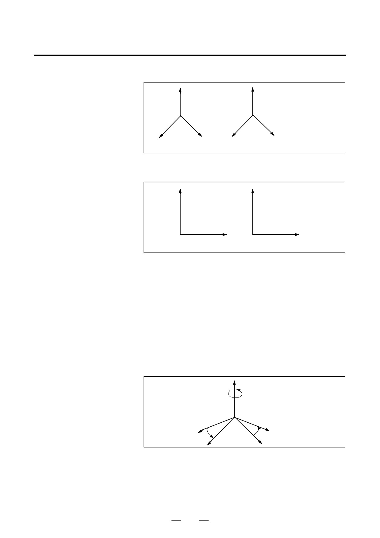
D Plane view (XY,YZ,ZY,XZ)
The following coordinate systems are selected.
Y
Z
P=0
P=1
XY
X
YZ
Y
Y
Z
P=2
P=3
ZY
Z
XZ
X
Fig. 12.1(e) Coordinate systems for the plane view
1101
12. GRAPHICS FUNCTION
OPERATION
B-63534EN/02
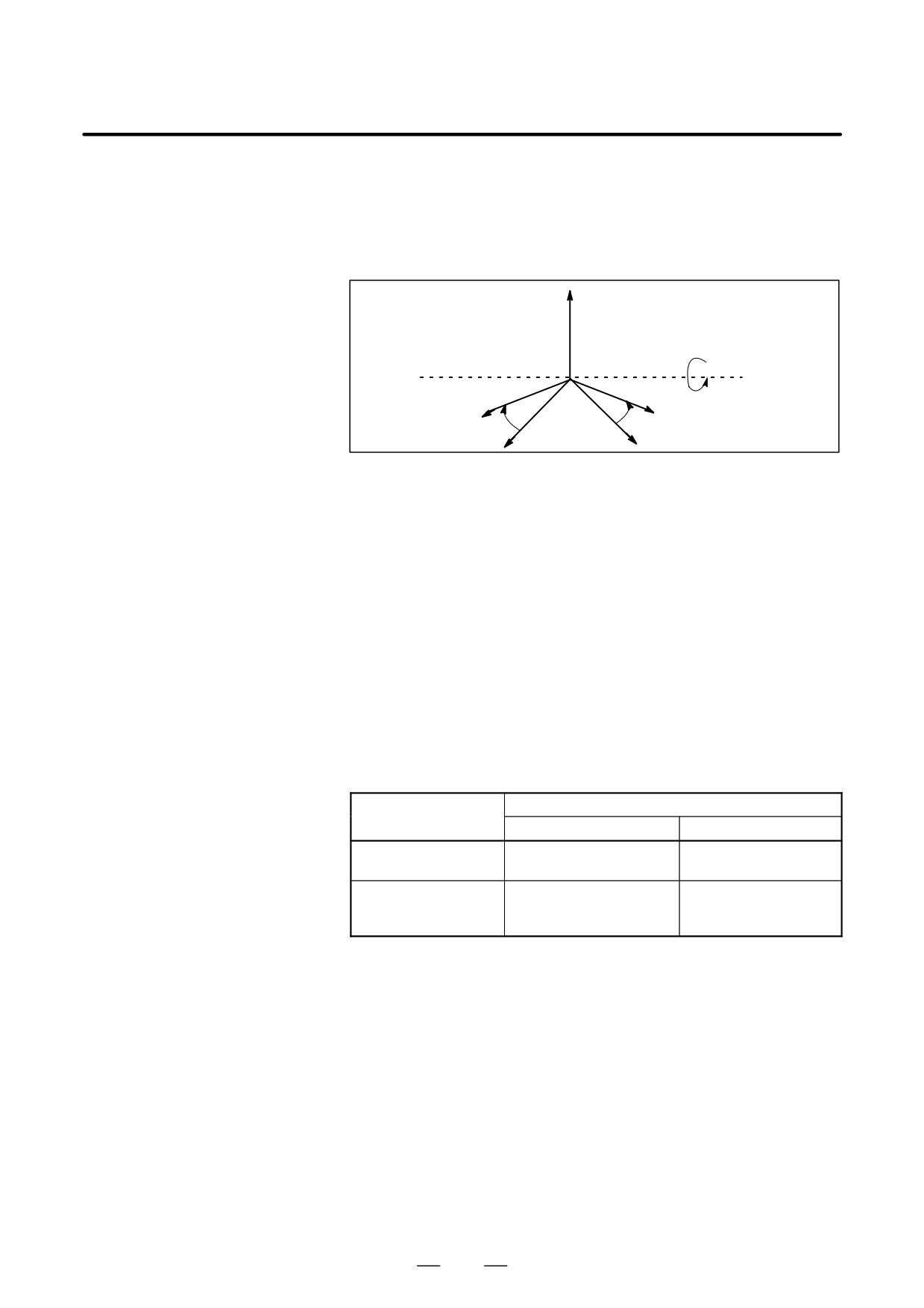
D Isometric projection
Projector view by isometric can be drawn.
(XYZ,ZXY)
Z
Y
P=5
P=4
X
Y
Z
X
XYZ
ZXY
Fig. 12.2.1 (a) Coordinate systems for the isometric projection
D Biplane view
Y
Z
P=6
X
X
Fig. 12.2.1 (b) Coordinate systems for the biplane view
Biplanes (XY and XZ) can be drawn simultaneously. The maximum and
minimum coordinate values must be set to draw the biplane view. The
maximum and minimum coordinate values can also be set by performing
automatic scaling
D ANGLE
The direction of the coordinate axis is set when the isometric projection
is the setting of the drawing screen. The direction is set by horizontal and
vertical rotation angles. The unit is expressed in degrees.
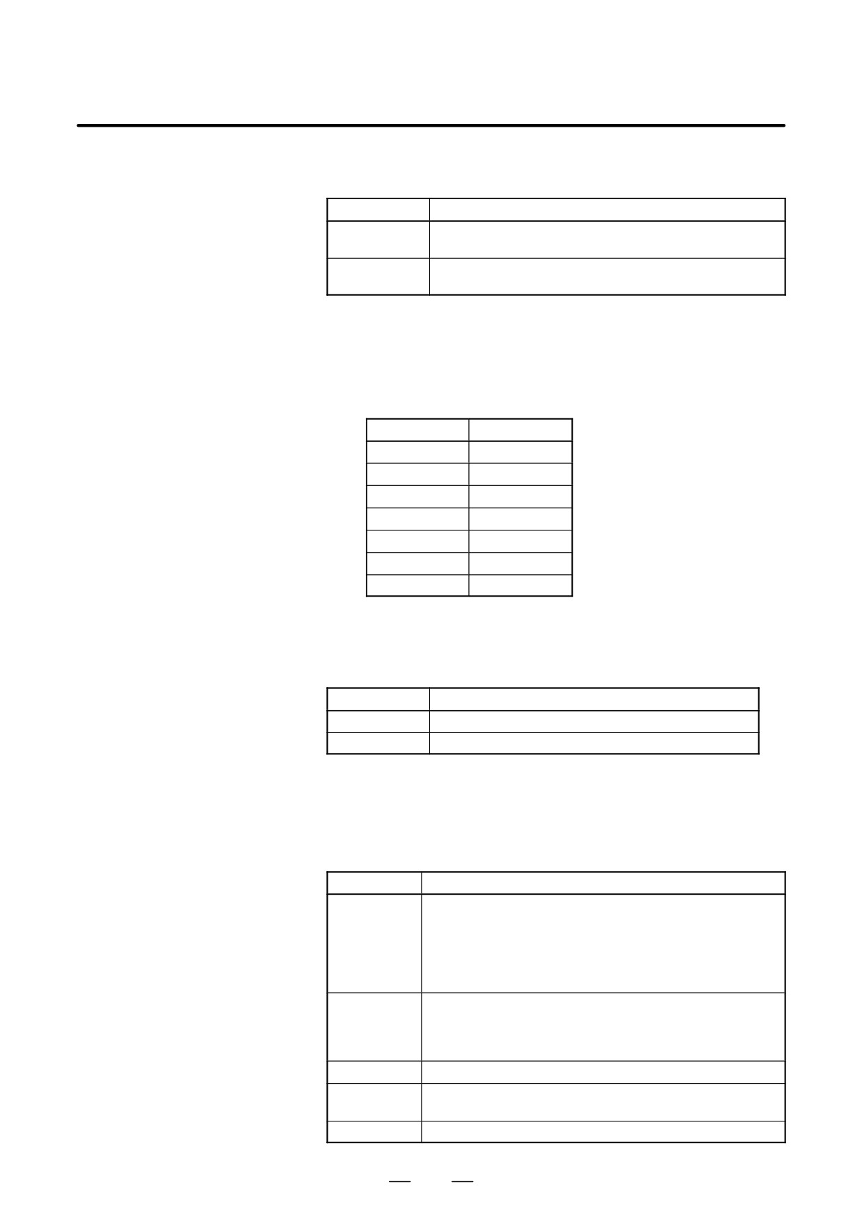
D ROTATION
The horizontal rotation angle is set in the range of -180°to +180°in
reference to the vertical axis. Set a positive value for clockwise rotation
of the coordinate axis. Thus, the direction of projection (visual arrow)
becomes counterclockwise.
Rotating
Fig. 12.2.1 (c) Rotating
1102
B-63534EN/02
OPERATION
12. GRAPHICS FUNCTION
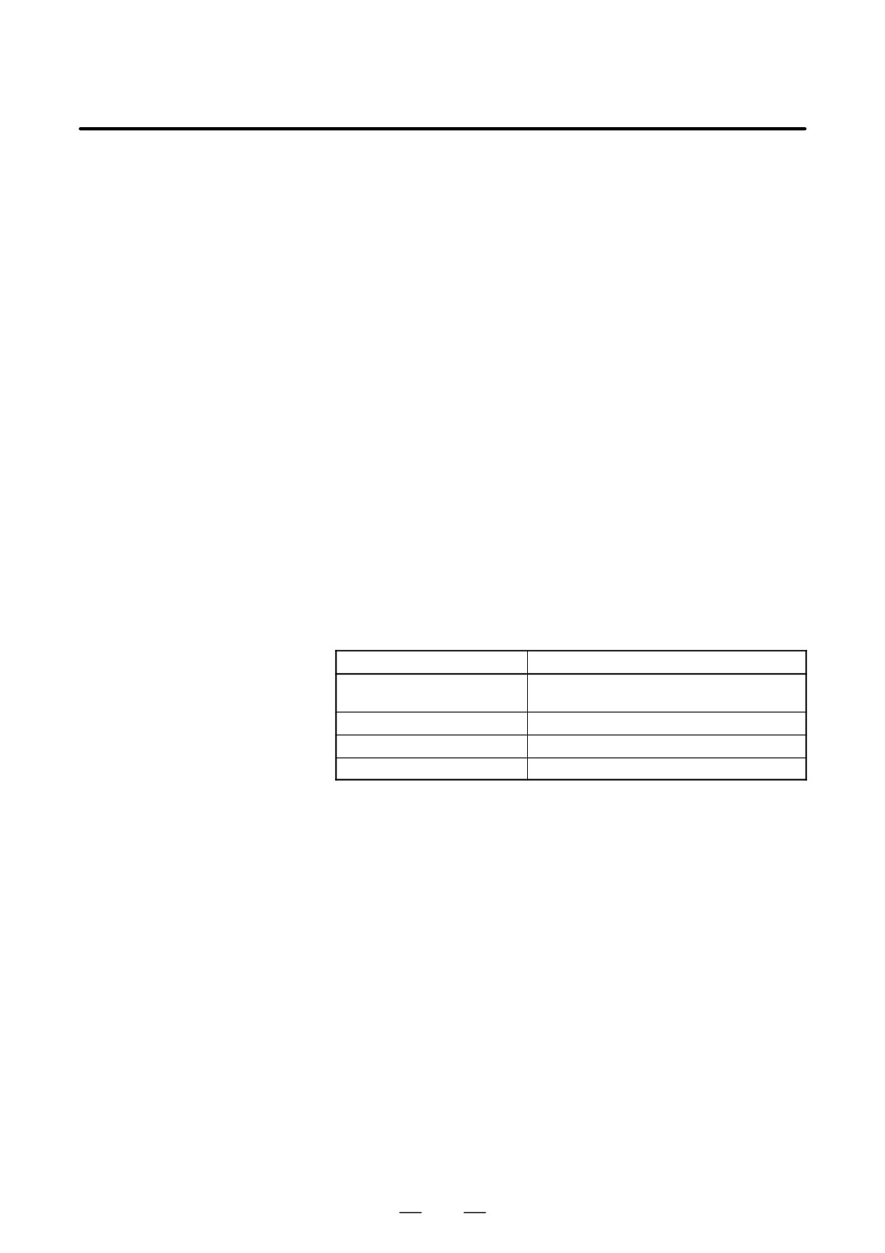
D TILTING
The tilting angle of the vertical axis is set in the range of -90°to +90°in
reference to the horizontal axis crossing the vertical axis at a right angle.
When a positive value is set, the vertical axis slants to the other side of
the graphic screen. Thus, the projection direction (arrow direction)
becomes the horizontal direction.
Tilting
Fig. 12.2.1 (d) Tilting
D SCALE
Set the magnification rate of drawing from 0.01 to 100.00. When 1.0 is
set, drawing is carried out in actual dimensions. When 0 is set, the
drawing magnification rate is automatically set based on the setting of
maximum and minimum coordinate values of drawing.
D CENTER OR MAX./MIN.
When a graphics (drawing) magnification of
0 is set, maximum
coordinates on the X-axis, Y-axis, and Z-axis in the workpiece
coordinate system must be set in addresses X, Y, and Z, and minimum
coordinates must be set in addresses I, J, and K, to specify the graphics
(drawing) range. For biplane view drawing, maximum and minimum
coordinates for drawing must be specified.
When a drawing magnification other than 0 is set, the X, Y, and Z
coordinates of the drawing center in the workpiece coordinate system
must be set in addresses X, Y, and Z. Addresses I, J, and K are not used.
The table below summarizes the setting requirements described above.
Setting
Setting the drawing
magnification rate
Address X/Y/Z
Address I/J/K
Drawing center coordinate
Other than 0
Ignored
value of X, Y, and Z axes
0 or biplane view
Drawing maximum
Drawing minimum
drawing
coordinate value of
coordinate value of
X, Y, and Z axes
X, Y, and Z axes
D START SEQ. NO. and
Set the start and end sequence numbers of drawing in five digits each. The
END SEQ. NO.
part program for drawing is executed from the head and only the part
enclosed by the start sequence and end sequence numbers is drawn. When
0 is commanded as the start sequence number, drawing is performed from
the head of the program. In addition, when 0 is commanded as the end
sequence number, drawing is performed up to the end of program. The
sequence number is referred to regardless of either main program or
subprogram.
1103
12. GRAPHICS FUNCTION
OPERATION
B-63534EN/02
D TOOL COMP.
It is possible to set whether the tool path is drawn by making the tool
length offset or cutter compensation valid or invalid.
Setting value
Tool length offset or cutter compensation
0
Perform drawing by making tool compensation valid
(An actual tool path is drawn.)
1
Perform drawing by making tool compensation invalid
(A programmed path is drawn.)
Always set 0 before drawing when indicating the mark of the current tool
position.
D COLOR
Specify the color of the tool path. In the case of monochrome it is not
required to set it. The relationship between the setting value and color is
as shown below:
Setting value
Color
0
White
1
Red
2
Green
3
Yellow
4
Blue
5
Purple
6
Light blue
⋅ PATH Specify the color of the tool path.
⋅ TOOL Specify the color of the current position mark of the tool.
⋅ AUTO CHANGE Set if for changing the color of the tool path
automatically according to the T -code command.
Setting value
Function
0
The color of the tool path is not changed.
1
The color of the tool path is changed automatically.
When 1 is set, the setting value of the color designation of PATH is
incremented by 1 every time the T code is commanded. At the same time,
the color of the tool path changes. If the setting value exceeds 6, it returns
to 0.
D Soft key functions on the
“PATH GRAPHIC
Software key
Function
[EXECUTION]”screen
[AUTO]
Automatic scaling is performed. Obtain the maximum and
minimum coordinates of the part program before performing
drawing, specify them for the maximum and minimum values of
drawing parameters, and set the drawing magnification rate to
0 before starting drawing. Thus, the tool path view is properly
laid out on the screen.
[START]
Drawing starts. When the [START] is pressed while the
drawing is not in STOP, the part program starts from the top of
the part program. Press the [START] while the drawing is in
stop to allow drawing to be carried out continuously.
[STOP]
Stop drawing. (Single block stop)
[REWIND]
Press this key to start drawing from the top of part program.
Searches for the beginning of a part program.
[ERASE]
Erase the tool path view which has been drawn.
1104
B-63534EN/02
OPERATION
12. GRAPHICS FUNCTION
D Graphic program
No part program which has not been registered in memory can be drawn.
Also, it is necessary that the M02 or M30 should be commanded at the
end of the part program.
D Mark for the tool current
The period of mark blinking is short when the tool is moving and becomes
position
longer when the tool stops.
The mark indicating the current position of tool is displayed on the XY
plane view when the biplane drawing is performed.
D Position mark
Parameter 6501 (CSR, bit 5) is used to specify whether to use J or x as
the mark for indicating the current tool position and the center of a
partially enlarged drawing.
D Display of the coordinate
Parameter 6500 (DPO, bit 5) is used to specify whether to display the
value
coordinates of the current position on the tool path drawing screen.
D Changing the coordinate
If a program specifies a coordinate system change, parameter 6501 (ORG,
system
bit 0) is used to specify whether to draw without changing the coordinate
system or to draw by regarding the current drawing position as the current
position in the new coordinate system.
Restrictions
D Graphic condition
If machine operation is not allowed, no drawing can be carried out. No
drawing can be made during machine operation. The setting data and
switches required for drawing are as shown below:
Setting data and switch
Status
Tool offset amount
Set it properly when performing drawing
while the tool offset amount becomes valid.
Single block
Off
Optional block skip
Set it properly.
Feed hold
Off
D Partial enlargement
The partial enlargement can be carried out on the plane view and isometric
projection view. No partial enlargement can be made in the drawing of
the biplane view.
D Tool current position
In dynamic graphics display, drawing cannot be executed while the
machine is operating even though this is possible in ordinary graphics
display (see III-12.1). However, after drawing is executed, the operator
can see how the tool moves along the tool path by operating the machine
while displaying the mark for the current position of the tool.
It is necessary that the setting data and switches related to the machine
operation should be the same status between drawing operation and
machining operation for properly displaying the current position of tool
on the drawn tool path.
D Two-path lathe control
For the two-path lathe control, two paths can not be displayed at the same
time.
1105
12. GRAPHICS FUNCTION
OPERATION
B-63534EN/02
12.2.2
The solid graphics draws the figure of a workpieces machined by the
movement of a tool.
Solid Graphics
The following graphic functions are provided :
1. Solid model graphic
Solid model graphic is drawn by surfaces so that the machined figure can
be recognized concretely.
2. Blank figure graphics
It is possible to draw a blank figure before machining.
A rectangular parallelepiped and a circular column or cylinder can be
drawn. A circular column or cylinder parallel to the X-axis, Y-axis, or
Z-axis can be selected.
3. Drawing of machining
It is possible to draw the progress of machining by simulation.
progress
4. Drawing of final machined
It is possible to draw the final finish machined figure.
figure
5. Changing of drawing direction
The user can choose from four drawing directions and eight tilting angles.
6. Plane view graphics
It is possible to draw XY plane views as well as solid model views. Height
of the workpiece is discriminated by color for color or brightness for
monochrome.
7. Triplane view graphic
In addition to a solid drawing, a triplane view can be drawn. The user can
choose from four types of plane view and side view positions. The user
can freely change the cross-section position of a side view.
8. Horizontal hole machining
It is possible to install tools in the direction which is parallel to the X or
Y axis as well as the Z axis.
9. Tool change during machining
It is possible to change tools during machining by the part program
command.
1106
B-63534EN/02
OPERATION
12. GRAPHICS FUNCTION
Solid graphics drawing procedure
Procedure
1
To draw a machining profile, necessary data must be set beforehand.
CUSTOM
So press the function key
GRAPH
(
GRAPH
for the small MDI).
The screen of ”SOLID GRAPHIC (PARAMETER)” is displayed.
SOLID GRAPHIC (PARAMETER)
O0000 N00003
BLANK FORM
P=
X=
0.000
Y=
0.000
Z=
0.000
I=
120.000
J=
100.000
K=
40.000
TOOL FORM
P=
2
R=
7.500
K=
0.000
PROJECTION
P=
3
Q=
1
R=
0
INTENSITY
P=
4
(0123456)
Q=
2
R=
1
START SEQ.NO.
N=
0
END SEQ.NO.
N=
0
ANIM. SPEED
N=
0
>_
MDI
****
***
***
14 : 42 : 17
PARAM
BLANK
EXEC
REVIEW
2
Use a cursor key to move the cursor to an item to be set.
3
Input numerics for the item at the cursor using the numeric key.
4
Press the
INPUT
Input numerics can be set by these operations and the cursor moves to the
next setting item automatically. The set data is retained even if the power
is turned off.
See Explanations for details on settings.
D SOLID GRAPHIC
5
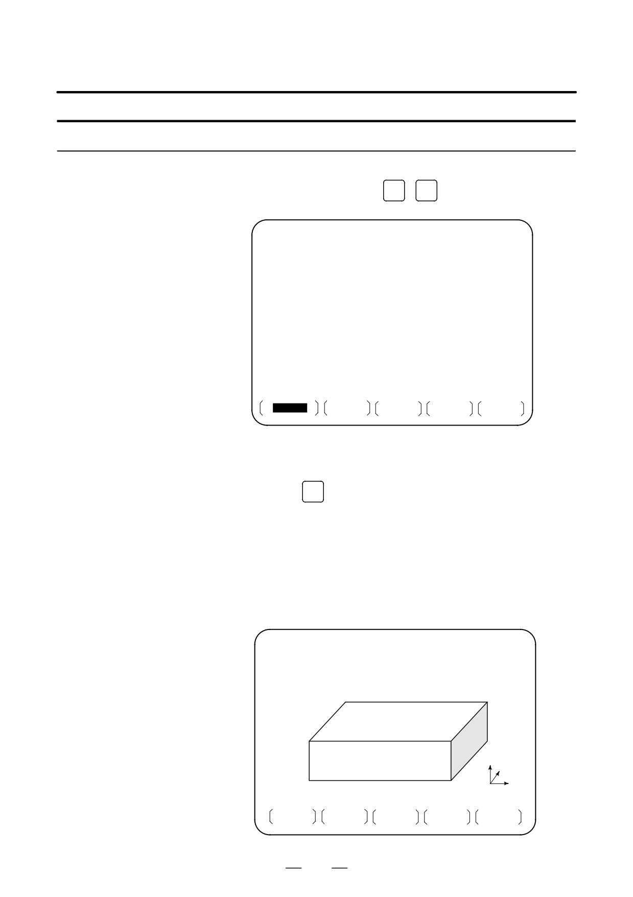
To draw a blank figure, display the SOLID GRAPHIC (BLANK)
(BLANK)
screen by pressing soft key [BLANK] on the SOLID GRAPHIC
(PARAMETER) screen of step 1 above.
SOLID GRAPHIC (BLANK)
O1126 N1126
Z
Y
X
MEM * * * *
***
***
10 : 10 : 40
ANEW
+ROT
-ROT
1107
12. GRAPHICS FUNCTION
OPERATION
B-63534EN/02
6
Press soft key [ANEW]. This allows the blank figure drawing to be
performed based on the blank figure data set.
7
Press soft keys
[+ROT]
[-ROT]
[+TILT], and
[-TILT], when
performing drawing by changing the drawing directions. Parameters
P and Q for the drawing direction are changed and the figure is
redrawn with the new parameters.
D SOLID GRAPHICS
8
Set the operation mode to the memory mode, press function key
(EXECUTION)
PROG
, and call the subject part program of drawing.
9
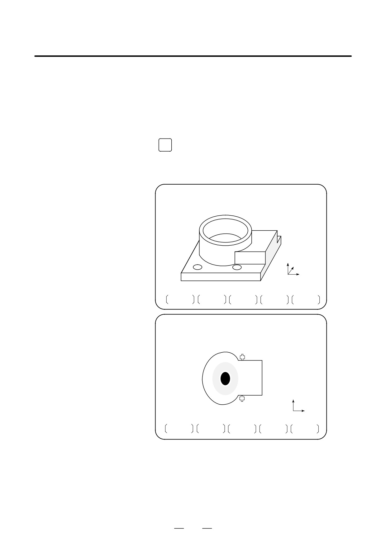
To draw a machining profile, display the SOLID GRAPHIC
(EXECUTION) screen by pressing soft key [EXEC] on the SOLID
GRAPHIC (PARAMETER) screen of step 1 above.
SOLID GRAPHIC (EXECUTION)
O1126 N01126
ÅÅÅ
ÅÅÅÅÅ
ÅÅÅÅÅÅÅ
ÅÅÅÅÅÅÅ
ÅÅÅÅÅÅ
Z
Y
ÔÅÅÅÔÔ
X
ÔÔ
ÔÔ
A.ST
F.ST
STOP
REWIND
SOLID GRAPHIC (EXECUTION)
O1126 N01126
Y
X
A.ST
F.ST
STOP
REWIND
1108
B-63534EN/02
OPERATION
12. GRAPHICS FUNCTION
10
Press soft key [(OPRT)] and press either soft key [A.ST] or [F.ST].
When [A.ST] is pressed, the status of machining in progress is drawn
by simulation. When [F.ST] is pressed, the profile during machining
is not drawn. Only the finished profile produced by the program is
drawn. This allows drawing to be started.
When “STOP” is not displayed at the lower right corner of the screen,
the program is executed from its head.
“DRAWING” blinks at the
lower right corner of CRT screen during drawing.
11
Press soft key [STOP] to stop drawing temporarily. Drawing is
stopped after drawing the current block and “STOP” blinks at the
lower right corner of CRT screen. Press soft key [A.ST] or [F.ST]
when restarting drawing. Press soft key [REWIND] and then the
[A.ST] or [F.ST] if redrawing from the head. It is possible to continue
drawing after changing the solid graphic parameters in temporary
stop.
12
When the end of program (M02 or M03) is executed, the drawing
ends and the blinking of “DRAWING” stops. Then, the final finish
figure is drawn on the CRT screen. The drawn figure view is retained
until the power is turned off as long as a new machine figure view is
drawn.
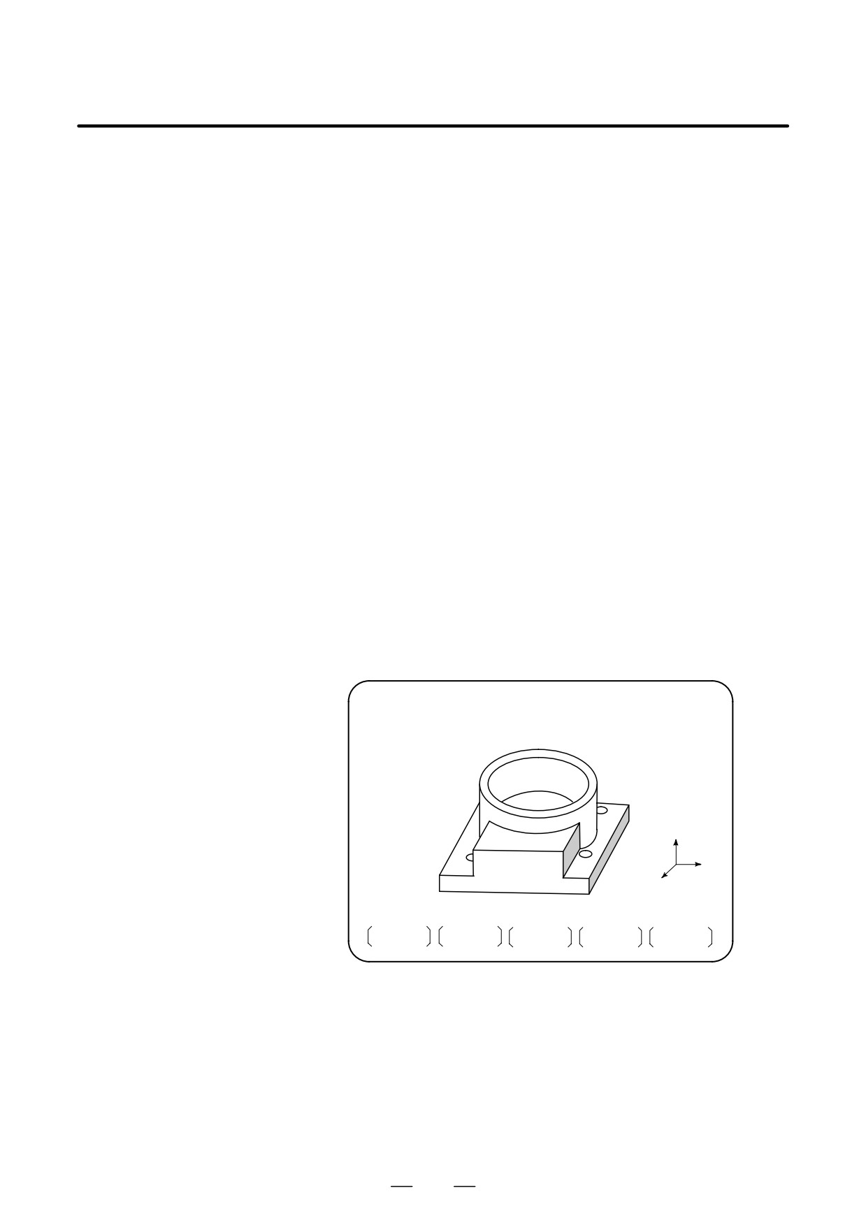
D REVIEW
13
The color, intensity, or drawing direction of a machining figure which
has been drawn can be changed and the figure redrawn.
To redraw the figure, first change the parameters for the color,
intensity, or drawing direction on the SOLID GRAPHIC
(PARAMETER) screen shown in step
1, then press soft key
[REVIEW] to display the SOLID GRAPHIC (REVIEW) screen.
SOLID GRAPHIC (REVIEW)
O1126 N01126
ÅÅÅÅ
ÅÅÅÅÅÅ
ÅÅÅÅÅÅ
ÅÅÅÅÅÅÔ
Z
ÅÅÅÅÅÅ
Y
Ô
ÔÔ
X
ANEW
+ROT
-ROT
+TILT
-TILT
14
Press soft key [(OPRT)], then press soft key [ANEW]. The machining
figure is redrawn with the color, intensity, or drawing direction set in
step 13.
1109
12. GRAPHICS FUNCTION
OPERATION
B-63534EN/02
15
To redraw the figure in a different mode, press soft key [+ROT],
[-ROT], [+TILT], or [-TILT]. Parameters P and Q for the drawing
direction are changed and the figure is redrawn with the new
paramaters.
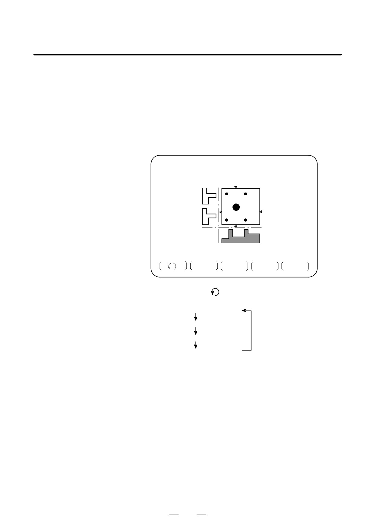
D Triplane view drawing
16
The machined figure can be drawn on the tri-plane view.
To draw a triplane view, press the rightmost soft key (next-menu key)
on the SOLID GRAPHIC (PARAMETER) screen of step 1 above, then
press soft key
[3-PLN] and [(OPRT)]. The SOLID GRAPHIC
(3-PLANE) screen appears.
SOLID GRAPHIC (3-PLANE)
01126 N01126
←
→
↑
↓
17
Each time soft key [
] is pressed, the side-view drawings dis-
played change as follows.
Right view and rear view
Rear view and left view
Left view and front view
Front view and right view
18
The sectional position of side view can be changed by the soft keys
[←], [→], [↑], and [↓].
With the sectional position of the left/right side view, the marks Y and
B indicating the sectional position can be moved using the soft keys
[←] and [→].
With the sectional position of rear/front side view, the marks " and A
indicating the sectional position can be moved using the soft keys [↑],
and [↓]. Keep the keys depressed to change sectional/views
continuously.
1110
B-63534EN/02
OPERATION
12. GRAPHICS FUNCTION
Explanations
GRAPHICS PARAMETER
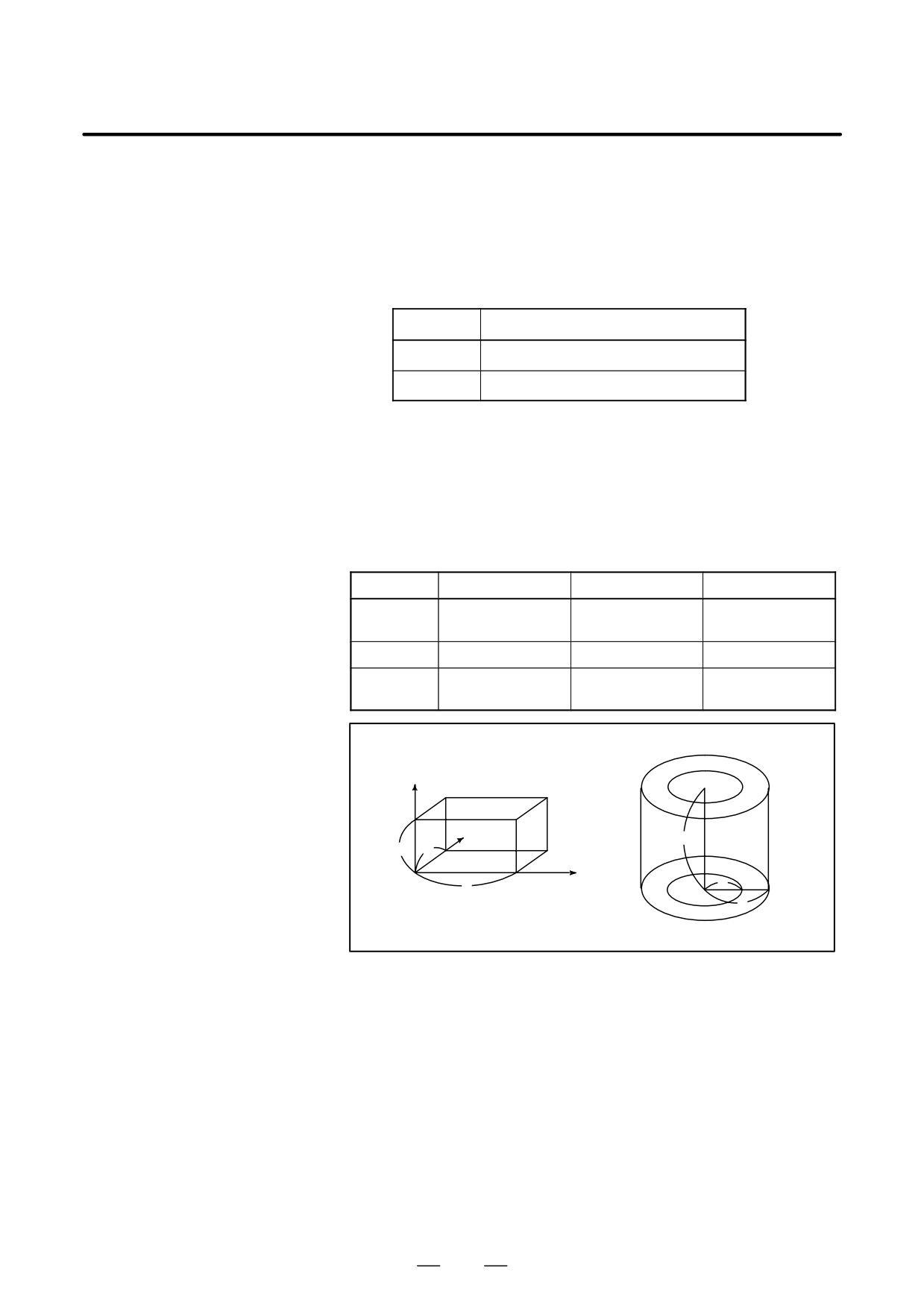
D BLANK FORM
♦ BLANK FORM (P)
Set the type of blank figure under P. The relationship between the setting
value and figure is as follows:
P
Blank figure
0
Rectangular parallelepiped (Cubed)
1
Column or cylinder (parallel to Z-axis)
♦ Material positions
Set the X-axis, Y-axis, and Z-axis coordinate values of standard point
(X,Y,Z)
of materials in workpiece coordinate system to the addresses X, Y, and Z.
The standard point of materials is the corner point in the negative
direction in the case of rectangular parallelepiped blank figure and the
center point of bottom in the case of column and cylinder materials.
♦ Material dimensions
Set the dimensions of materials. The relationship between the addresses
(I,J,K)
I, J, and K and setting value is as shown below:
Material
I
J
K
Rectangular
Length in X-axis
Length in Y-axis
Length in Z-axis
direction
direction
direction
Column
Radius of circle
0
Length of column
Cylinder
Radius of external
Radius of internal
Length of cylinder
circle
circle
Z
Y
K
K J
X
(X,Y,Z)
I
J
(X,Y,Z)
I
1111
12. GRAPHICS FUNCTION
OPERATION
B-63534EN/02
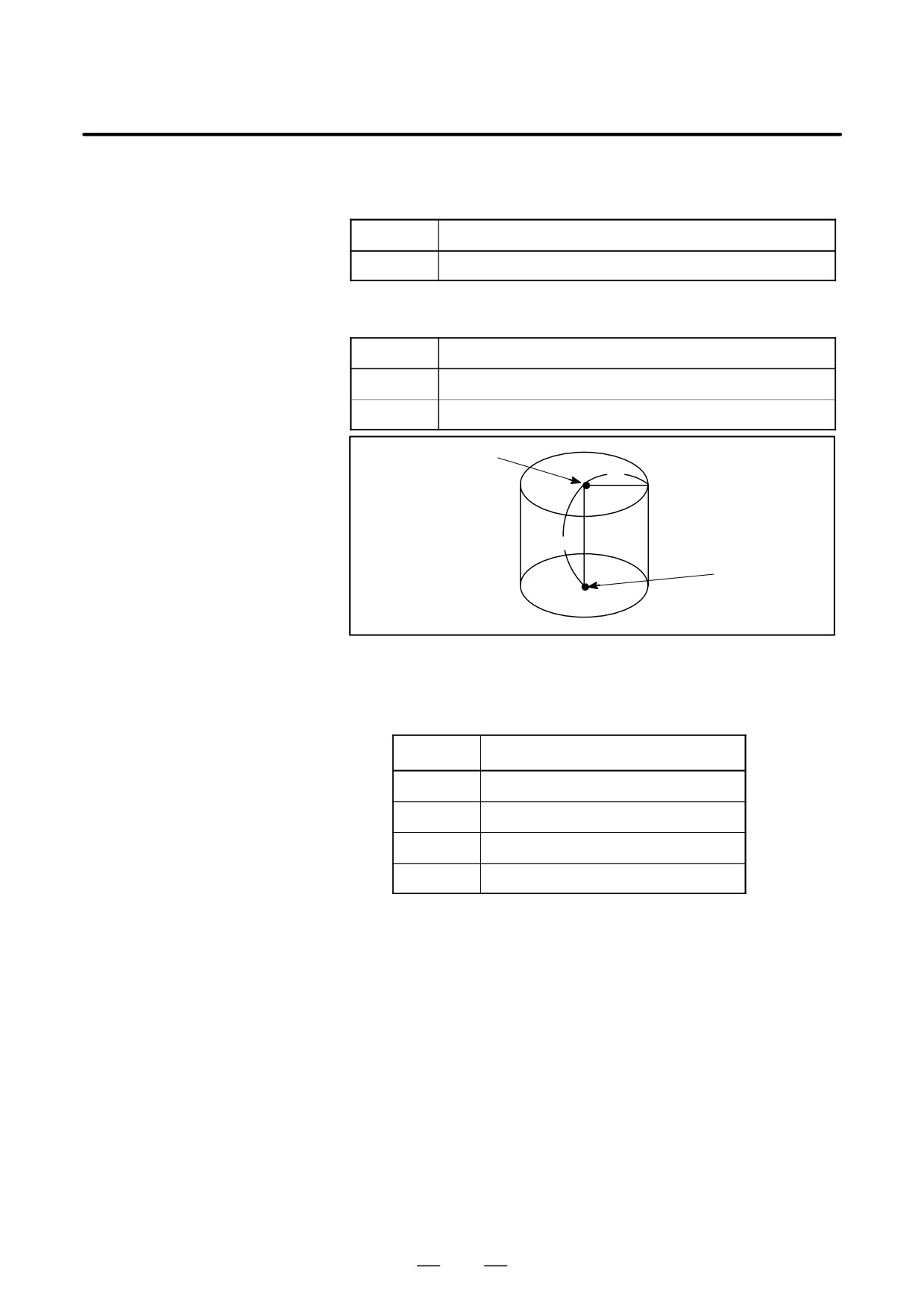
D TOOL FORM
♦ Machining tool
Set the machining direction of tools.
orientation (P)
P
Machining direction of tools
0,1
Parallel to the Z-axis (perform machining from the + direction)
♦ Dimensions of tools
Set the dimensions of tool. The relationship between the displayed
(R,K)
address and setting value is as shown below:
Address
Setting numerics
R
Radius of tool
K
Distance from the program point to tool tip (normally 0)
Program point
R
K
Tip of the tool
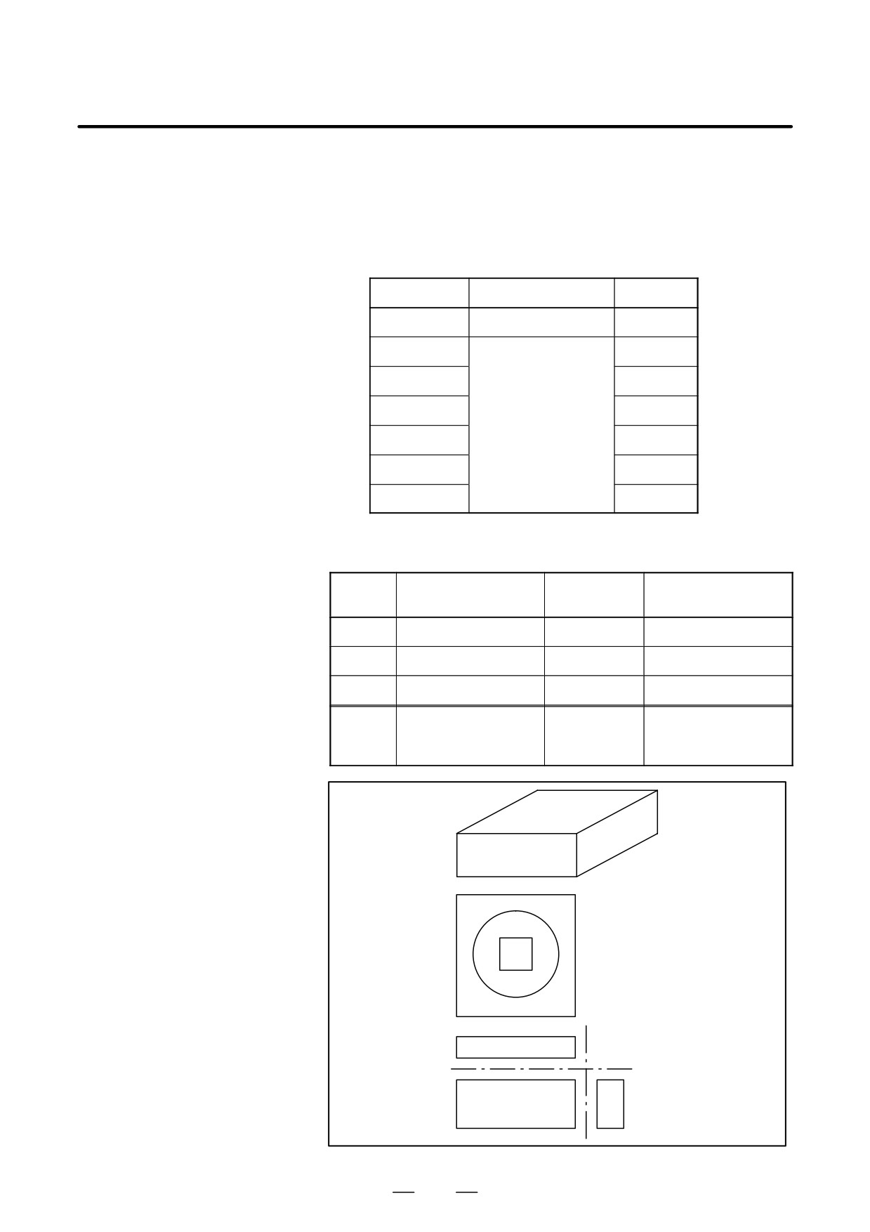
D PROJECTION
♦ Graphics method
The relationship between graphic method and direction and setting value
and direction (P)
is as shown below:
P
Graphic method and direction
0, 4
Oblique projection view (+ X-axis)
1, 5
Oblique projection view (+ Y-axis)
2, 6
Oblique projection view (- X-axis)
3, 7
Oblique projection view (-Y-axis)
This setting value can also be incremented or decremented by the soft
keys [+ROT] or [- ROT]. In this case, if the setting value exceeds 7, it
returns to 0. If it is smaller than 0, it becomes 7.
Direction of the vertical axis is fixed in Z-axis.
♦ VERTICAL AXIS (R)
1112
B-63534EN/02
OPERATION
12. GRAPHICS FUNCTION
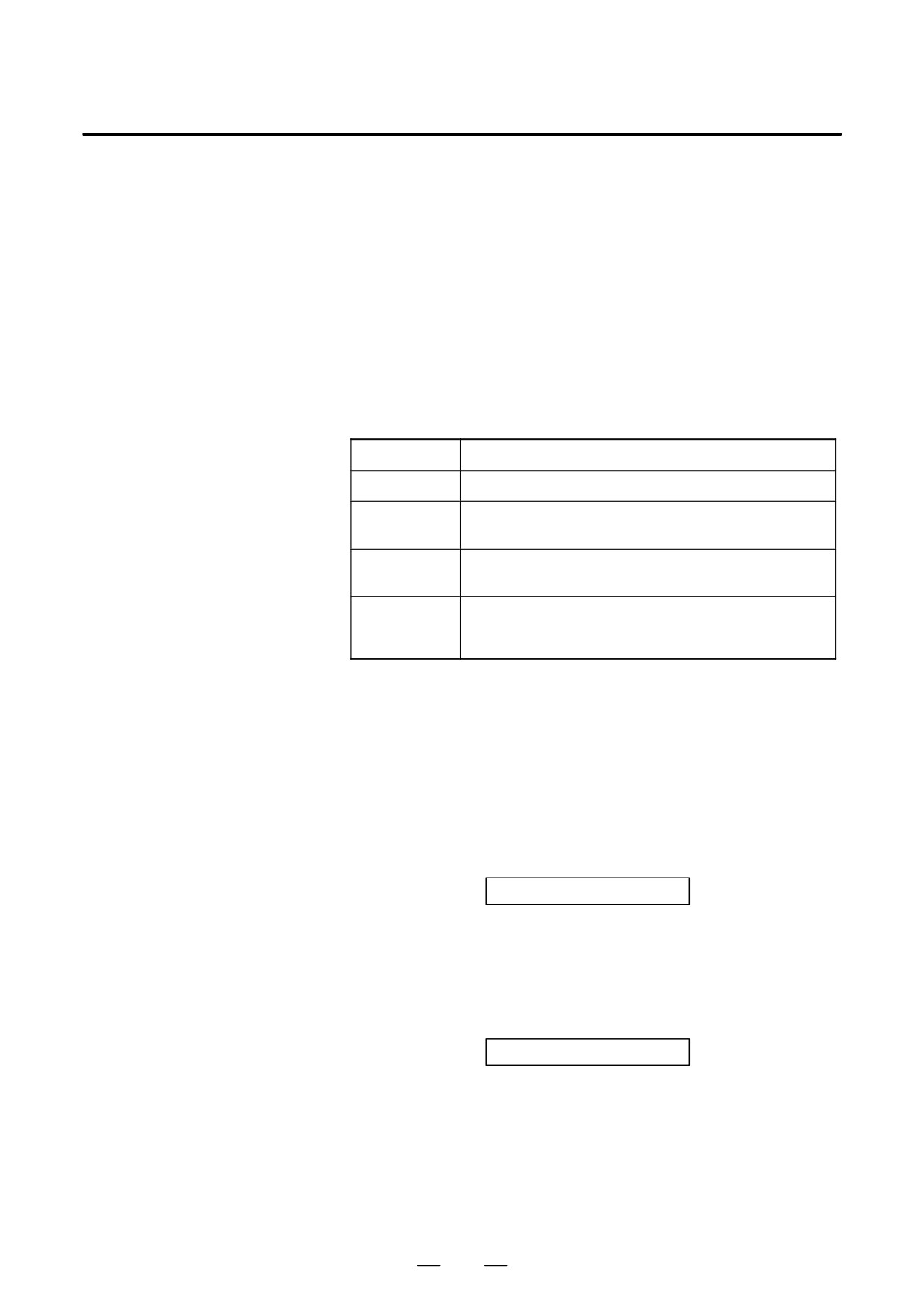
D INTENSITY
Specify the intensity of the drawing screen when performing drawing on
the monochrome, and the color of the drawing screen when performing
drawing on the color screen. The relationship between the setting,
intensity, and color is as shown below:
However, when the plane view is displayed on the monochrome. The
brighter surface, whichever is specified by P or Q becomes the top surface.
Setting value
Intensity
Color
0
Maximum brightness
White
1
Red
2
Dark
Green
3
↓
Yellow
4
Blue
Light
5
Purple
6
Light blue
The relationship between the display address, surface, and line on the
machined figure view is as shown below:
Oblique projection
Address
Plane view
Triplane view
view
P
Upper surface
Upper surface
Upper/lower surface
Q
Side surface
Middle surface
Left/right surface
R
Ridge
Ridge
Ridge
Remarks
The intensity/color of
Lower surface
The intensity/color of
front surface is
is blank
plane view is between
between P and Q
P and Q
P
Q
P+Q
Oblique projection view
P
Q
Plane view
Blank
P
Triplan view
P+Q
Q
1113
12. GRAPHICS FUNCTION
OPERATION
B-63534EN/02
D START SEQ. NO. and
Specify the start sequence number and end sequence number of each
END SEQ. NO.
drawing in a five-digit numeric. The subject part program is executed
from the head. But only the part enclosed by the start sequence number
and end sequence numeric is drawn. When 0 is commanded as the start
sequence number, the program is drawn from its head. When 0 is
commanded as the end sequence number, the program is drawn to its end.
The comparison of sequence number is performed regardless of main
program and subprogram.
D ANIM. SPEED
Set interval of animated simulation drawing ranging from 0 to 255.
Every time the machining proceeds by the number set, the drawing is
repeated. If 0 is set, drawing is repeated at every 1 block execution.
D Soft key functions on the
“SOLID GRAPHIC
Soft key
Function
(EXECUTION)”screen
[A.ST]
Simulate and draw the progress of machining.
No figure during machining is drawn and only the final
[F.ST]
finish figure by that program is drawn.
When pressed, stops drawing at the end of block (single
[STOP]
block stop).
Press this key to perform drawing from the head of part
[REWIND]
program. Heading is performed automatically after execu-
tion of program end (M02/M30).
D Graphics program
No part program which has not been registered in memory can be drawn.
It is also necessary that the M02 or M30 be commanded at the end of the
part program.
D Specifying the blank
It is possible to specify BLANK FORM and TOOL FORM in the part
form and tool form in the
program. The command format is as shown below. If it is commanded
part program
during execution of drawing, the item corresponding to the screen of
“SOLID GRAPHIC (PARAMETER)” is set and drawing continues with the
set data.
S Command of BLANK FORM
G10 L90 P_X_Y_Z_I_J_K_ ;
The command value succeeding the address is the same as the
numeric set to the address being displayed at the item of BLANK
FORM of “SOLID GRAPHIC (PARAMETER)”. If BLANK FORM
is commanded, drawing continues after a new blank figure is
drawn.
S Command of TOOL FORM
G10 L91 P_R_K_ ;
The command value succeeding the address is the same as the
numeric set to the address being displayed at the item of TOOL
FORM of screen “SOLID GRAPHIC (PARAMETER)”. If 0 is
commanded with the tool radius value, no machining simulation
is performed thereafter.
D Display of the coordinate
Parameter 6500 (DPO, bit 5) is used to specify whether to display the
value
coordinates of the current position on SOLID GRAPHIC screen.
1114
B-63534EN/02
OPERATION
12. GRAPHICS FUNCTION
D TOOL COMP.
In solid graphics, parameter 6501 (TLC, bit 1) is used to specify whether
to apply tool length offset.
D Graphic method
Parameter 6501 (3PL, bit 2) is used to select whether to draw a triplane
view with the third-angle or first-angle projection.
D Ridge drawing
Parameter 6501 (RID, bit 3) is used to specify whether to draw ridges in
plane view drawing.
D Display mode
Parameter 6501 (FIM, bit 4) is used to specify whether to display a solid
graphics in the rough mode or in the fine mode. When a solid graphics
is drawn in the fine mode, the drawing speed is slower than when drawn
in the rough mode.
D Cross section position
In triplane drawing, a value can be specified for changing the position of
change
the cross section while the soft key is held down. A value from 0 to 10
can be set. When 0 is specified, a value of 1 is used. (Parameter No. 6515)
1115
12. GRAPHICS FUNCTION
OPERATION
B-63534EN/02
Examples
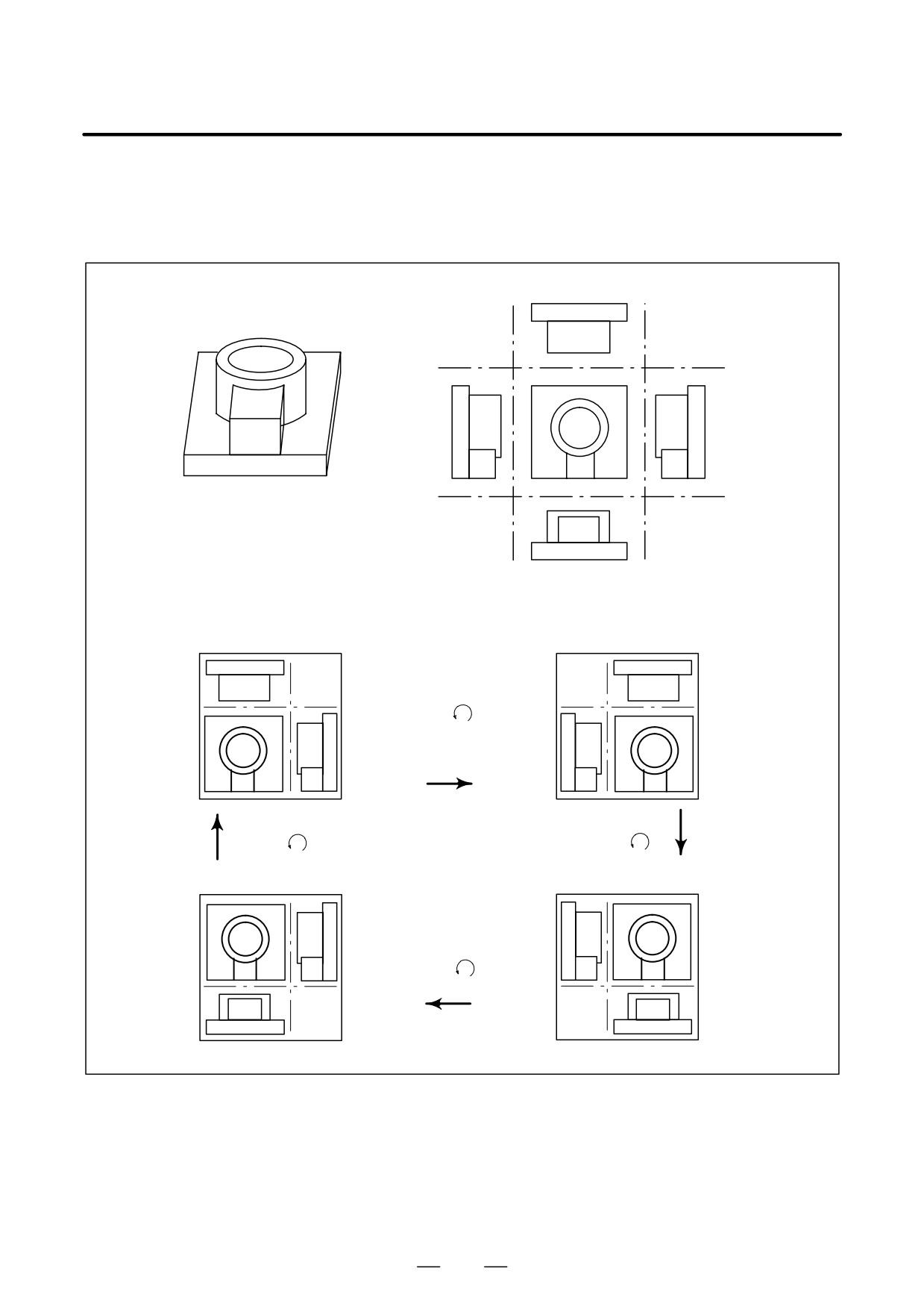
D Side view selection in
triplane drawing
Example) The side views of the figure below are illustrated.
Rear view
Top view
Left side view
Right side view
Front view
In the above figure, the side views displayed are switched as follows.
Right view and rear view
Rear view and left view
Press [
]
Press
[
]
Press
[
]
Front view and right view
Left view and front view
Press
[
]
1116
B-63534EN/02
OPERATION
12. GRAPHICS FUNCTION
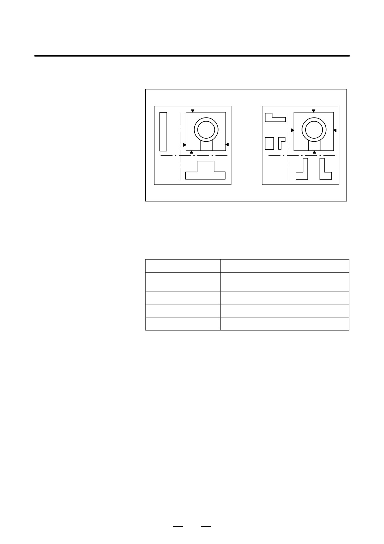
D Cross section position
Some examples of cross-sectional views are given below for the left view
selection in triplane
and front view shown on the previous page.
drawing
Sectional view 1
Sectional view 2
Õ
ÕÕÕ
Õ
ÕÕÕ
Õ
ÕÕÕ
Õ
ÕÕÕ
Õ
ÕÕÕ
ÕÕÕ
ÕÕÕ
ÕÕÕ
ÕÕÕÕÕ
ÕÕÕÕÕ
ÕÕÕÕÕ
ÕÕÕÕÕ
Limitations
D Graphic condition
If the machine operation is not enabled, no drawing can be made. No
drawing can be made during operation of machine. The main setting data
and switches needed on drawing are as shown below:
Setting data/switch
Status needed for drawing
It is necessary to set the cutter compensation
Tool offset value
value properly. The tool length offset is ignored.
Single block
Off
Optional block skip
Properly set it.
Feed hold
Off
D Tool form
Tools which set the tool figure are limited to the cylinder figure
(equivalent to flat end mill).
D Helical interpolation
In solid graphics, paths based on helical interpolation cannot be drawn.
D Two-path control
For the two-path control, two paths can not be displayed at the same time.
1117
12. GRAPHICS FUNCTION
OPERATION
B-63534EN/02
12.3
The background drawing function enables the drawing of a figure for one
program while machining a workpiece under the control of another
BACKGROUND
program.
DRAWING
Procedure for Background Drawing
Procedure
CUSTOM
1
Press the
GRAPH
function key (
for a small MDI).
GRAPH
2
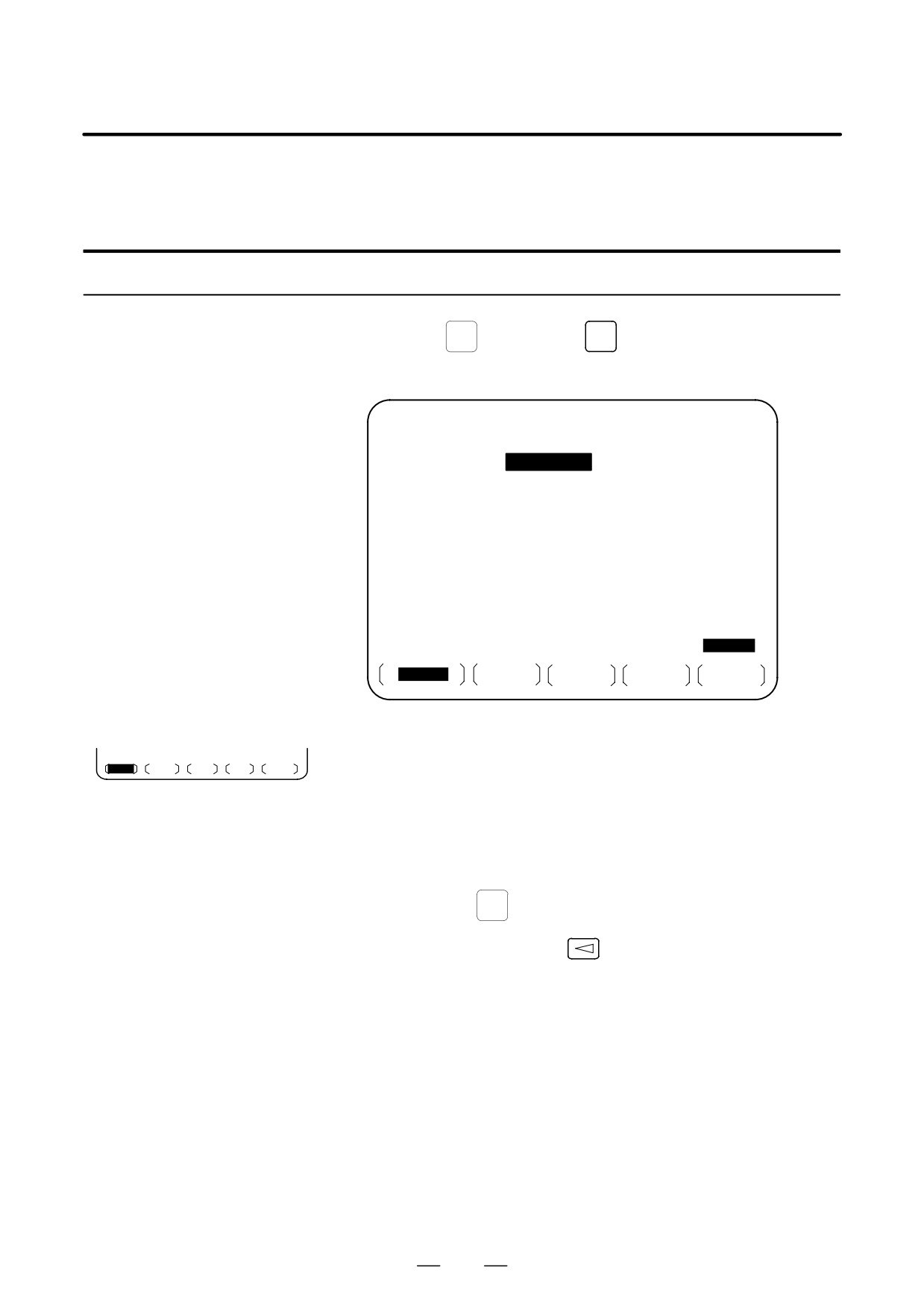
Press the [PARAM] soft key. The following screen appears:
PATH GRAPHIC
(PARAMETER-1) O0001 N00001
AXES
P=
0
(XY=0, YZ=1, ZY=2, XZ=3, XYZ=4, ZXY=5,
2P=6)
ANGLE
ROTATION
A=
0
TILTING
A=
0
SCALE
K=
0.00
CENTER OR MAX./MIN.
X=
0.000
X=
0.000
X=
0.00
X=
0.000
X=
0.000
X=
0.00
START SEQ. NO. N=
0
END SEQ. NO. N=
0
>_
MDI
21 : 20 : 05
BGGRP
****
***
***
PARAM
EXEC
SCALE
POS
(OPRT)
3
Press the [(OPRT)] soft key.
O SRH INPUT
4
To select the program to be used for drawing, enter the number of that
program, then press the [O SRH] soft key. (The O number at the top
right of the screen indicates the selected program.) Repeatedly
pressing only the [O SRH] soft key selects the registered programs in
turn.
To input a graphic parameter, the [INPUT] soft key can be used
instead of the
INPUT
MDI key.
5
Press the left-most soft key
(return menu key), to return the soft
keys to the state existing upon the completion of step 2.
6
Perform dynamic graphic display, as described in Section III-12.2.
Explanations
D Program selection
Immediately after entering background drawing mode, the program
which was selected previously remains selected. Any program can be
selected for background drawing, by using the background drawing
screen.
If no program is selected prior to entering background drawing mode, the
program number is set to 0. In such a case, drawing cannot be started until
the program to be used for drawing is specified.
1118
B-63534EN/02
OPERATION
12. GRAPHICS FUNCTION
D Tool offsets
Separate tool offsets are internally provided for machining and
background drawing. Upon starting drawing or when selecting a program
for drawing, the tool offset data for machining is copied to the tool offset
data for background drawing. Changing a tool offset by using a G10
command during machining does not affect that for background drawing.
Similarly, changing a tool offset by using a G10 command during drawing
does not affect that for machining.
D Parameters
The same parameters are used for both background drawing and actual
machining.
D Workpiece coordinate
Workpiece coordinate system offsets, part of the parameters, are provided
offsets
separately for machining and background drawing. Upon selecting a
program for drawing, the workpiece coordinate system offset data for
machining is copied to the workpiece coordinate system offset data for
background drawing. Changing a workpiece coordinate system offset by
using a G10 command during machining does not affect that for
background drawing. Similarly, changing a workpiece coordinate system
offset by using a G10 command during drawing does not affect that for
machining.
D Macro variables
Macro variables are provided separately for machining and background
drawing. Upon selecting a program for drawing, the macro variables for
machining are copied to the macro variables for background drawing.
Changing a macro variable by using a G10 command during machining
does not affect that for background drawing. Similarly, changing a macro
variable using a G10 command during drawing does not affect that for
machining.
D
OFFSET
function key
OFFSET
SETTING
When bit 6 (BGOF) of parameter No. 3109 is set to 1, pressing the
SETTING
function key on the background drawing screen displays the tool offsets,
workpiece coordinate system offsets, and macro variables for background
drawing. In such a case,
BGGRP
is displayed at the bottom right of the
screen, to indicate that data for background drawing is being displayed.
1119