FANUC Series 16i/160i/160is-MB, Series 18i/180i/180is-MB5, Series 18i/180i/180is-MB. Operator's Manual - page 36
11. SETTING AND DISPLAYING DATA
OPERATION
B-63534EN/02
11.4
OFFSET
Press function key
SETTING
to display or set tool compensation values and
SCREENS
other data.
DISPLAYED BY
This section describes how to display or set the following data:
OFFSET
FUNCTION KEY
SETTING
1. Tool offset value
#OFFSETSETTING#
2. Settings
3. Run time and part count
4. Workpiece origin offset value
5. Custom macro common variables
6. Pattern menu and pattern data
7. Software operator’s panel
8. Tool life management data
9. Chopping data
10. Rotary table dynamic fixture offset data
This section also describes measurement of tool length and the sequence
number comparison and stop function.
The pattern menu, pattern data, software operator’s panel, and tool life
management data depend on the specifications of the machine tool
builder. See the manual issued by the machine tool builder for details.
1030
OPERATION
11. SETTING AND DISPLAYING DATA
B-63534EN/02
11.4.1
Tool offset values, tool length offset values, and cutter compensation
values are specified by D codes or H codes in a program. Compensation
Setting and Displaying
values corresponding to D codes or H codes are displayed or set on the
the Tool Offset Value
screen.
Procedure for setting and displaying the tool offset value
Procedure
OFFSET
1
Press function key
SETTING
For the two-path control, select the tool post for which tool
compensation values are to be displayed with the tool post selection
switch.
OFFSET
2
Press chapter selection soft key [OFFSET] or press
SETTING
several
times until the tool compensation screen is displayed.
The screen varies according to the type of tool offset memory.
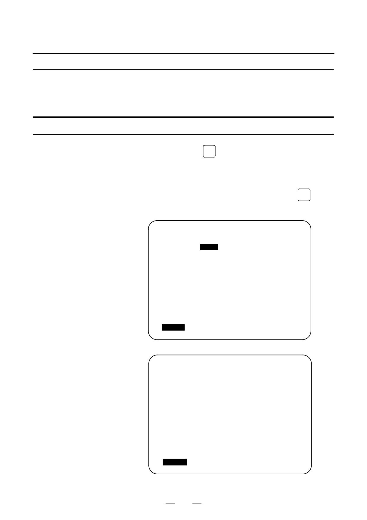
OFFSET
O0001 N00000
NO.
DATA
NO.
DATA
001
1.000
009
0.000
002
-2.000
010
-7.500
003
0.000
011
12.000
004
5.000
012
-20.000
005
0.000
013
0.000
006
0.000
014
0.000
007
0.000
015
0.000
008
0.000
016
0.000
ACTUAL POSITION (RELATIVE)
X
0.000
Y
0.000
Z
0.000
> _
MDI **** *** ***
16:05:59
[
OFFSET ] [ SETING ]
[ WORK ]
[
]
[ (OPRT) ]
Tool offset memory A
OFFSET
O0001 N00000
NO. GEOM(H)
WEAR(H)
GEOM(D)
WEAR(D)
001
10.000
0.000
0.000
0.000
002
-1.000
0.000
0.000
0.000
003
0.000
0.000
0.000
0.000
004
20.000
0.000
0.000
0.000
005
0.000
0.000
0.000
0.000
006
0.000
0.000
0.000
0.000
007
0.000
0.000
0.000
0.000
008
0.000
0.000
0.000
0.000
ACTUAL POSITION (RELATIVE)
X
0.000
Y
0.000
Z
0.000
> _
MDI **** *** ***
16:05:59
[ OFFSET
]
[ SETING ] [ WORK ] [
]
[ (OPRT) ]
Tool offset memory C
1031
11. SETTING AND DISPLAYING DATA
OPERATION
B-63534EN/02
3
Move the cursor to the compensation value to be set or changed using
page keys and cursor keys, or enter the compensation number for the
compensation value to be set or changed and press soft key
[NO.SRH].
4
To set a compensation value, enter a value and press soft key [INPUT].
To change the compensation value, enter a value to add to the current
value (a negative value to reduce the current value) and press soft key
[+INPUT]. Or, enter a new value and press soft key [INPUT].
Explanations
D Decimal point input
A decimal point can be used when entering a compensation value.
D Other setting method
An external input/output device can be used to input or output a tool offset
value. See III-8. A tool length offset value can be set by measuring the
tool length as described in the next subsection.
D Tool offset memory
There are tool offset memories A, B, and C, which are classified as
follows:
Tool offset memory A
D codes and H codes are treated the same. Tool geometry compensation
and tool wear compensation are treated the same.
Tool offset memory B
D codes and H codes are treated the same. Tool geometry compensation
and tool wear compensation are treated differently.
Tool offset memory C
D codes and H codes are treated differently. Tool geometry
compensation and tool wear compensation are treated differently.
D Disabling entry of
The entry of compensation values may be disabled by setting bit 0 (WOF)
compensation values
and bit 1 (GOF) of parameter 3290 (not applied to tool offset memory A).
And then, the input of tool compensation values from the MDI can be
inhibited for a specified range of offset numbers. The first offset number
for which the input of a value is inhibited is set in parameter No. 3294.
The number of offset numbers, starting from the specified first number,
for which the input of a value is inhibited is set in parameter No. 3295.
Consecutive input values are set as follows:
1) When values are input for offset numbers, starting from one for which
input is not inhibited to one for which input is inhibited, a warning is
issued and values are set only for those offset numbers for which input
is not inhibited.
2) When values are input for offset numbers, starting from one for which
input is inhibited to one for which input is not inhibited, a warning is
issued and no values are set.
1032
OPERATION
11. SETTING AND DISPLAYING DATA
B-63534EN/02
D
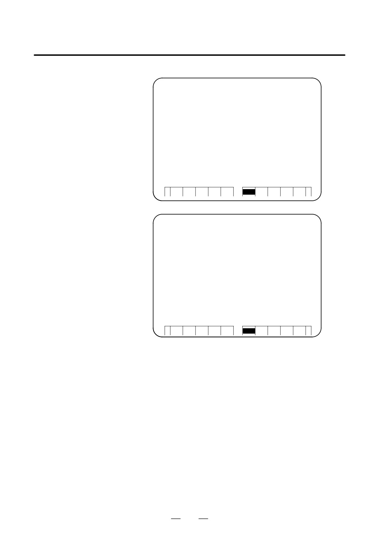
12 soft keys display unit
OFFSET
O0000 N00000
NO.
DATA NO.
DATA
ACTUAL POSITION (RELATIVE)
001
0.000
017
0.000
002
0.000
018
0.000
X-12345.678
003
0.000
019
0.000
004
0.000
020
0.000
Y-12345.678
005
0.000
021
0.000
006
0.000
022
0.000
Z-12345.678
007
0.000
023
0.000
008
0.000
024
0.000
A-12345.678
009
0.000
025
0.000
010
0.000
026
0.000
B-12345.678
011
0.000
027
0.000
012
0.000
028
0.000
C-12345.678
013
0.000
029
0.000
014
0.000
030
0.000
7-12345.678
015
0.000
031
0.000
016
0.000
032
0.000
8-12345.678
>_
MDI **** *** ***
20:45:00
OFFSET
SETTING
(OPRT)
Tool offset memory A
OFFSET
O0000 N00000
(LENGTH)
(RADIUS) ACTUAL POSITION
NO.
GEOM
WEAR
GEOM
WEAR
(RELATIVE)
001
0.000
0.000
0.000
0.000
X
0.000
002
0.000
0.000
0.000
0.000
Y
0.000
003
0.000
0.000
0.000
0.000
Z
0.000
004
0.000
0.000
0.000
0.000
A
0.000
005
0.000
0.000
0.000
0.000
B
0.000
006
0.000
0.000
0.000
0.000
C
0.000
007
0.000
0.000
0.000
0.000
7
0.000
008
0.000
0.000
0.000
0.000
8
0.000
009
0.000
0.000
0.000
0.000
010
0.000
0.000
0.000
0.000
011
0.000
0.000
0.000
0.000
012
0.000
0.000
0.000
0.000
013
0.000
0.000
0.000
0.000
014
0.000
0.000
0.000
0.000
015
0.000
0.000
0.000
0.000
016
0.000
0.000
0.000
0.000
>_
MDI **** *** ***
20:45:00
OFFSET
SETTING
(OPRT)
Tool offset memory C
1033
11. SETTING AND DISPLAYING DATA
OPERATION
B-63534EN/02
11.4.2
The length of the tool can be measured and registered as the tool length
offset value by moving the reference tool and the tool to be measured until
Tool Length
they touch the specified position on the machine.
Measurement
The tool length can be measured along the X-, Y-, or Z-axis.
Procedure for tool length measurement
Procedure
1
Use manual operation to move the reference tool until it touches the
specified position on the machine (or workpiece.)
2
Press function key
POS
several times until the current position
display screen with relative coordinates is displayed.
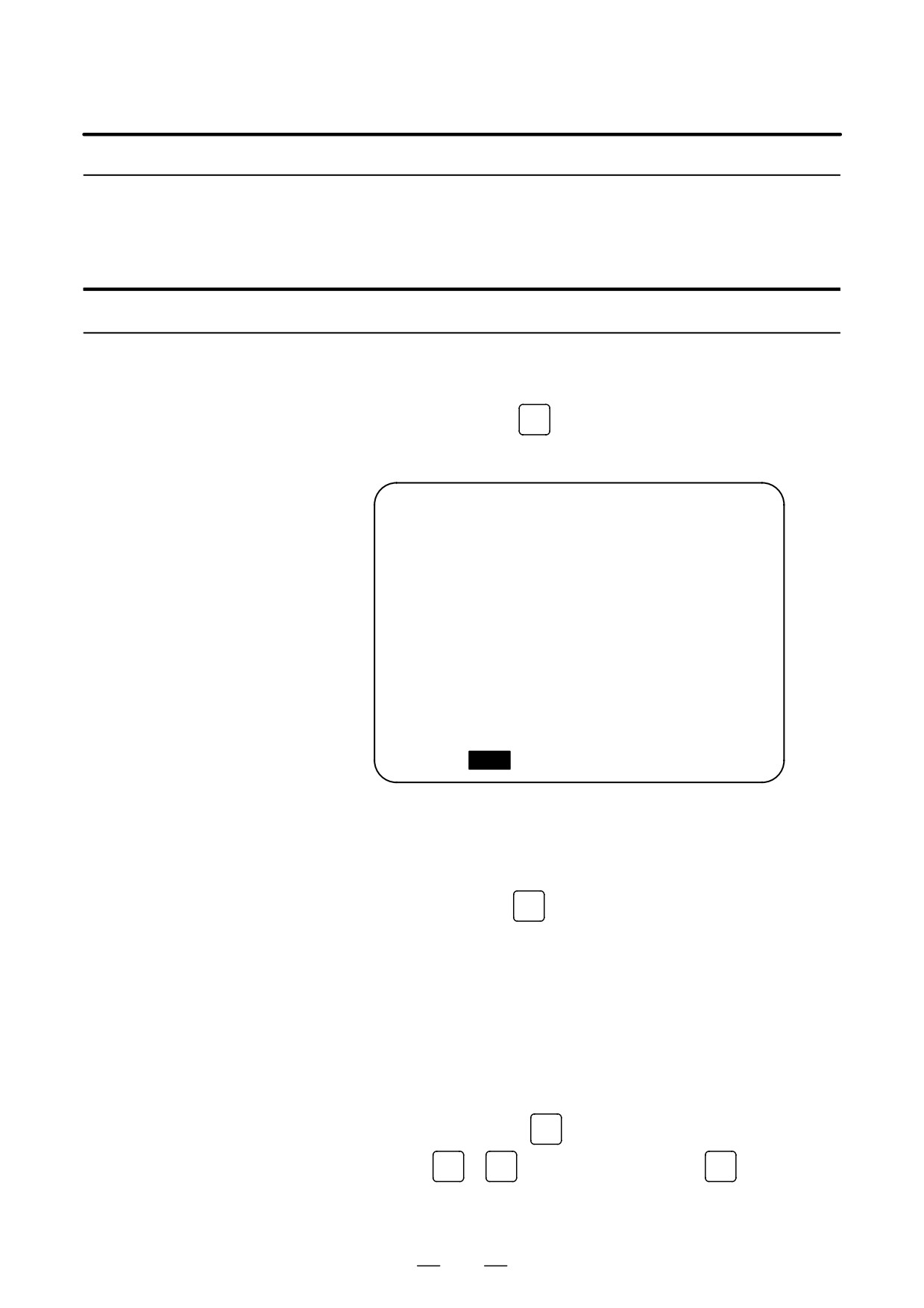
ACTUAL POSITION(RELATIVE)
O1000 N00010
X
123.456
Y
363.233
Z
0.000
PART COUNT
5
RUN TIME
0H15M CYCLE TIME 0H 0M38S
ACT.F
3000 MM/M
S 0 T0000
MEM STRT MTN ***
09:06:35
[ ABS ]
[
REL ]
[ ALL ]
[ HNDL ]
[ OPRT ]
3
Reset the relative coordinate for the Z-axis to 0 (see III-11.1.2 for
details).
OFFSET
4
Press function key
SETTING
several times until the tool compensation
screen is displayed.
5
Use manual operation to move the tool to be measured until it touches
the same specified position. The difference between the length of the
reference tool and the tool to be measured is displayed in the relative
coordinates on the screen.
6
Move the cursor to the compensation number for the target tool (the
cursor can be moved in the same way as for setting tool compensation
values).
7
Press the address key
Z
If either
X
or
Y
key is depressed instead of
Z
key, the X or Y
axis relative coordinate value is input as an tool length compensation
value.
1034
OPERATION
11. SETTING AND DISPLAYING DATA
B-63534EN/02
8
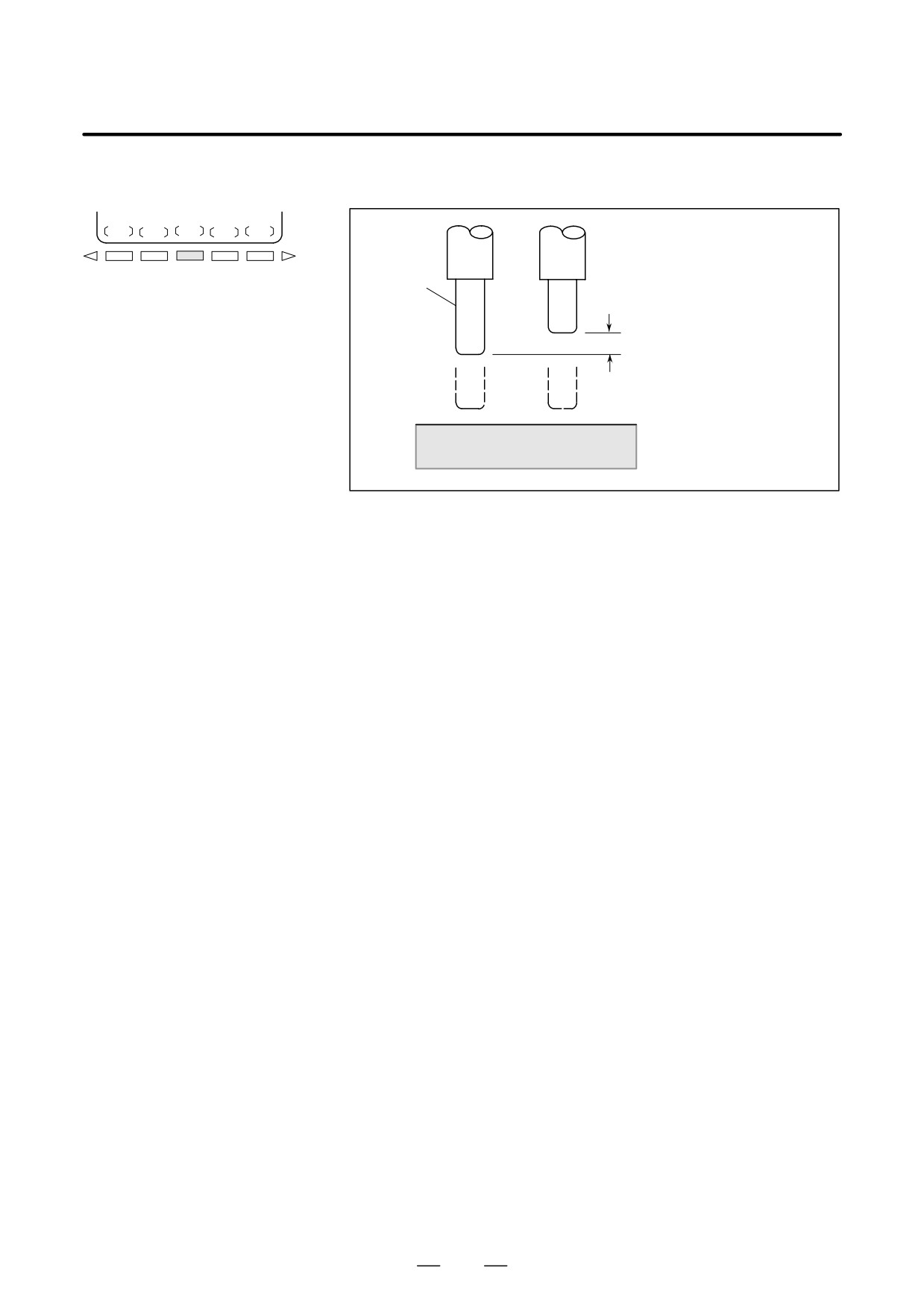
Press the soft key [INP.C.]. The Z axis relative coordinate value is
input and displayed as an tool length offset value.
INP.C.
Reference
ÇÇ ÇÇÇ
tool
ÇÇ
ÇÇÇ
ÇÇ ÇÇÇ
The difference is set as a tool
ÇÇ
length offset value
A prefixed position
1035
11. SETTING AND DISPLAYING DATA
OPERATION
B-63534EN/02
11.4.3
Data such as the TV check flag and punch code is set on the setting data
screen. On this screen, the operator can also enable/disable parameter
Displaying and
writing, enable/disable the automatic insertion of sequence numbers in
Entering Setting Data
program editing, and perform settings for the sequence number
comparison and stop function.
See III-10.2 for automatic insertion of sequence numbers.
See III-11.4.4 for the sequence number comparison and stop function.
This subsection describes how to set data.
Procedure for setting the setting data
Procedure
1
Select the MDI mode.
OFFSET
2
Press function key
SETTING
3
Press soft key [SETING] to display the setting data screen.
This screen consists of several pages.
Press page key
or PAGE
until the desired screen is displayed.
PAGE
An example of the setting data screen is shown below.
SETTING (HANDY)
O0001 N00000
PARAMETER WRITE
=
1 (0:DISABLE 1:ENABLE)
TV CHECK
=
0 (0:OFF
1:ON)
PUNCH CODE
=
1 (0:EIA
1:ISO)
INPUT UNIT
=
0 (0:MM
1:INCH)
I/O CHANNEL
=
0 (0-3:CHANNEL NO.)
SEQUENCE NO.
=
0 (0:OFF
1:ON)
TAPE FORMAT
=
0 (0:NO CNV 1:F15)
SEQUENCE STOP
=
0 (PROGRAM NO.)
SEQUENCE STOP
=
0 (SEQUENCE NO.)
> _
MDI **** *** ***
16:05:59
[ OFFSET ] [ SETING
]
[ WORK ]
[
]
[ (OPRT) ]
SETTING (HANDY)
O0001 N00000
MIRROR IMAGE
X
=
0
(0:OFF
1:ON)
MIRROR IMAGE
Y
=
0 (0:OFF
1:ON)
MIRROR IMAGE
Z
=
0 (0:OFF
1:ON)
> _
MDI **** *** ***
16:05:59
[ OFFSET ] [ SETING
]
[ WORK
]
[
]
[ (OPRT) ]
1036

OPERATION
11. SETTING AND DISPLAYING DATA
B-63534EN/02
4
Move the cursor to the item to be changed by pressing cursor keys
,
,
, or
5
Enter a new value and press soft key [INPUT].
Contents of settings
D PARAMETER WRITE
Setting whether parameter writing is enabled or disabled.
0 : Disabled
1 : Enabled
D TV CHECK
Setting to perform TV check.
0 : No TV check
1 : Perform TV check
D PUNCH CODE
Setting code when data is output through reader puncher interface.
0 : EIA code output
1 : ISO code output
D INPUT UNIT
Setting a program input unit, inch or metric system
0 : Metric
1 : Inch
D I/O CHANNEL
Using channel of reader/puncher interface.
0 : Channel 0
1 : Channel 1
2 : Channel 2
3 : Channel 3
D SEQUENCE STOP
Setting of whether to perform automatic insertion of the sequence number
or not at program edit in the EDIT mode.
0 : Does not perform automatic sequence number insertion.
1 : Perform automatic sequence number insertion.
D TAPE FORMAT
Setting the F15 tape format conversion.
0 : Tape format is not converted.
1 : Tape format is converted.
See II. PROGRAMMING for the F15 tape format.
D SEQUENCE STOP
Setting the sequence number with which the operation stops for the
sequence number comparison and stop function and the number of the
program to which the sequence number belongs
D MIRROR IMAGE
Setting of mirror image ON/OFF for each axes.
0 : Mirror image off
1 : Mirror image on
D Others
Page key
or PAGE
can also be pressed to display the SETTING
PAGE
(TIMER) screen. See III-11.4.5 for this screen.
1037
11. SETTING AND DISPLAYING DATA
OPERATION
B-63534EN/02
11.4.4
If a block containing a specified sequence number appears in the program
being executed, operation enters single block mode after the block is
Sequence Number
executed.
Comparison and Stop
Procedure for sequence number comparison and stop
Procedure
1
Select the MDI mode.
OFFSET
2
Press function key
SETTING
3
Press chapter selection soft key [SETING].
4
Press page key
or PAGE
several times until the following screen
PAGE
is displayed.
SETTING (HANDY)
O0001 N00000
PARAMETER WRITE
=
1 (0:DISABLE 1:ENABLE)
TV CHECK
=
0 (0:OFF
1:ON)
PUNCH CODE
=
1 (0:EIA
1:ISO)
INPUT UNIT
=
0 (0:MM
1:INCH)
I/O CHANNEL
=
0 (0-3:CHANNEL NO.)
SEQUENCE NO.
=
0 (0:OFF
1:ON)
TAPE FORMAT
=
0 (0:NO CNV
1:F10/11)
SEQUENCE STOP
=
0 (PROGRAM NO.)
SEQUENCE STOP
=
11
(SEQUENCE NO.)
> _
MDI **** *** ***
16:05:59
[ OFFSET ] [
SETING
]
[ WORK ]
[
]
[ (OPRT) ]
5
Enter in (PROGRAM NO.) for SEQUENCE STOP the number (1 to
9999) of the program containing the sequence number with which
operation stops.
6
Enter in (SEQUENCE NO.) for SEQUENCE STOP (with five or less
digits) the sequence number with which operation is stopped.
7
When automatic operation is executed, operation enters single block
mode at the block containing the sequence number which has been
set.
1038
OPERATION
11. SETTING AND DISPLAYING DATA
B-63534EN/02
Explanations
D Sequence number after
After the specified sequence number is found during the execution of the
the program is executed
program, the sequence number set for sequence number compensation
and stop is decremented by one. When the power is turned on, the setting
of the sequence number is 0.
D Exceptional blocks
If the predetermined sequence number is found in a block in which all
commands are those to be processed within the CNC control unit, the
execution does not stop at that block.
Example
N1 #1=1 ;
N2 IF [#1 EQ 1] GOTO 08 ;
N3 GOTO 09 ;
N4 M98 P1000 ;
N5 M99 ;
In the example shown above, if the predetermined sequence number is
found, the execution of the program does not stop.
D Stop in the canned cycle
If the predetermined sequence number is found in a block which has a
canned-cycle command, the execution of the program stops after the
return operation is completed.
D When the same
If the predetermined sequence number appears twice or more in a
sequence number is
program, the execution of the program stops after the block in which the
found several times in
predetermined sequence number is found for the first time is executed.
the program
D Block to be repeated a
If the predetermined sequence number is found in a block which is to be
specified number of
executed repeatedly, the execution of the program stops after the block is
times
executed specified times.
1039
11. SETTING AND DISPLAYING DATA
OPERATION
B-63534EN/02
11.4.5
Various run times, the total number of machined parts, number of parts
required, and number of machined parts can be displayed. This data can
Displaying and Setting
be set by parameters or on this screen (except for the total number of
Run Time, Parts Count,
machined parts and the time during which the power is on, which can be
and Time
set only by parameters).
This screen can also display the clock time. The time can be set on the
screen.
Procedure for Displaying and Setting Run Time, Parts Count and Time
Procedure
1
Select the MDI mode.
OFFSET
2
Press function key
SETTING
3
Press chapter selection soft key [SETING].
4
Press page key
or PAGE
several times until the following screen
PAGE
is displayed.
SETTING (TIMER)
O0001 N00000
PARTS TOTAL
=
14
PARTS REQUIRED
=
0
PARTS COUNT
=
23
POWER ON
=
4H 31M
OPERATING TIME
=
0H 0M
0S
CUTTING TIME
=
0H 37M
5S
FREE PURPOSE
=
0H 0M
0S
CYCLE TIME
=
0H 0M
0S
DATE
=
2001/07/05
TIME
=
11:32:52
> _
MDI **** *** ***
16:05:59
[ OFFSET ]
[ SETING
]
[ WORK
]
[
]
[ (OPRT) ]
5
To set the number of parts required, move the cursor to PARTS
REQUIRED and enter the number of parts to be machined.
6
To set the clock, move the cursor to DATE or TIME, enter a new date
or time, then press soft key [INPUT].
Display items
D PARTS TOTAL
This value is incremented by one when M02, M30, or an M code specified
by parameter 6710 is executed. This value cannot be set on this screen.
Set the value in parameter 6712.
D PARTS REQUIRED
It is used for setting the number of machined parts required.
When the “0” is set to it, there is no limitation to the number of parts.
Also, its setting can be made by the parameter (NO. 6713).
1040

OPERATION
11. SETTING AND DISPLAYING DATA
B-63534EN/02
D PARTS COUNT
This value is incremented by one when M02, M30, or an M code specified
by parameter 6710 is executed. The value can also be set by parameter
6711. In general, this value is reset when it reaches the number of parts
required. Refer to the manual issued by the machine tool builder for
details.
D POWER ON
Displays the total time which the power is on. This value cannot be set
on this screen but can be preset in parameter 6750.
D OPERATING TIME
Indicates the total run time during automatic operation, excluding the
stop and feed hold time.
This value can be preset in parameter 6751 or 6752.
D CUTTING TIME
Displays the total time taken by cutting that involves cutting feed such as
linear interpolation (G01) and circular interpolation (G02 or G03). This
value can be preset in parameter 6753 or 6754.
D FREE PURPOSE
This value can be used, for example, as the total time during which coolant
flows. Refer to the manual issued by the machine tool builder for details.
D CYCLE TIME
Indicates the run time of one automatic operation, excluding the stop and
feed hold time. This is automatically preset to 0 when a cycle start is
performed at reset state. It is preset to 0 even when power is removed.
D DATA and TIME
Displays the current date and time. The date and time can be set on this
screen.
Limitations
D Usage
When the command of M02 or M30 is executed, the total number of
machined parts and the number of machined parts are incremented by one.
Therefore, create the program so that M02 or M30 is executed every time
the processing of one part is completed. Furthermore, if an M code set
to the parameter (NO. 6710) is executed, counting is made in the similar
manner. Also, it is possible to disable counting even if M02 or M30 is
executed (parameter PCM (No. 6700#0) is set to 1). For details, see the
manual issued by machine tool builders.
Restrictions
D Run time and part count
Negative value cannot be set. Also, the setting of “M” and “S” of run time
settings
is valid from 0 to 59.
Negative value may not be set to the total number of machined parts.
D Time settings
Neither negative value nor the value exceeding the value in the following
table can be set.
Item
Maximum value
Item
Maximum value
Year
2085
Hour
23
Month
12
Minute
59
Day
31
Second
59
1041
11. SETTING AND DISPLAYING DATA
OPERATION
B-63534EN/02
11.4.6
Displays the workpiece origin offset for each workpiece coordinate
system (G54 to G59, G54.1 P1 to G54.1 P48 and G54.1 P1 to G54.1
Displaying and Setting
P300) and external workpiece origin offset. The workpiece origin offset
the Workpiece Origin
and external workpiece origin offset can be set on this screen.
Offset Value
Procedure for Displaying and Setting the Workpiece Origin Offset Value
Procedure
OFFSET
1
Press function key
SETTING
2
Press chapter selection soft key [WORK].
The workpiece coordinate system setting screen is displayed.
WORK COORDINATES
O0001 N00000
(G54)
NO. DATA
NO. DATA
00
X
0.000
02
X 152.580
(EXT) Y
0.000
(G55) Y 234.000
Z
0.000
Z 112.000
01
X 20.000
03
X 300.000
(G54) Y 50.000
(G56) Y 200.000
Z 30.000
Z 189.000
> _
S 0 T0000
MDI **** *** ***
16:05:59
[ OFFSET ] [ SETING ] [ WORK ] [
]
[ (OPRT) ]
3
The screen for displaying the workpiece origin offset values consists
of two or more pages. Display a desired page in either of the
following two ways:
D Press the page up
or page down PAGE
key.
PAGE
D Enter the workpiece coordinate system number (0 : external
workpiece origin offset, 1 to 6: workpiece coordinate systems G54
to G59, P1 to P48 : workpiece coordinate systems G54.1 P1 to
G54.1 P48, P1 to P300 : workpiece coordinate systems G54.1 P1
to G54.1 P300) and press operation selection soft key [NO.SRH].
4
Turn off the data protection key to enable writing.
5
Move the cursor to the workpiece origin offset to be changed.
6
Enter a desired value by pressing numeric keys, then press soft key
[INPUT]. The entered value is specified in the the workpiece origin
offset value. Or, by entering a desired value with numeric keys and
pressing soft key [+INPUT], the entered value can be added to the
previous offset value.
7
Repeat 5 and 6 to change other offset values.
8
Turn on the data protection key to disable writing.
1042
OPERATION
11. SETTING AND DISPLAYING DATA
B-63534EN/02
11.4.7
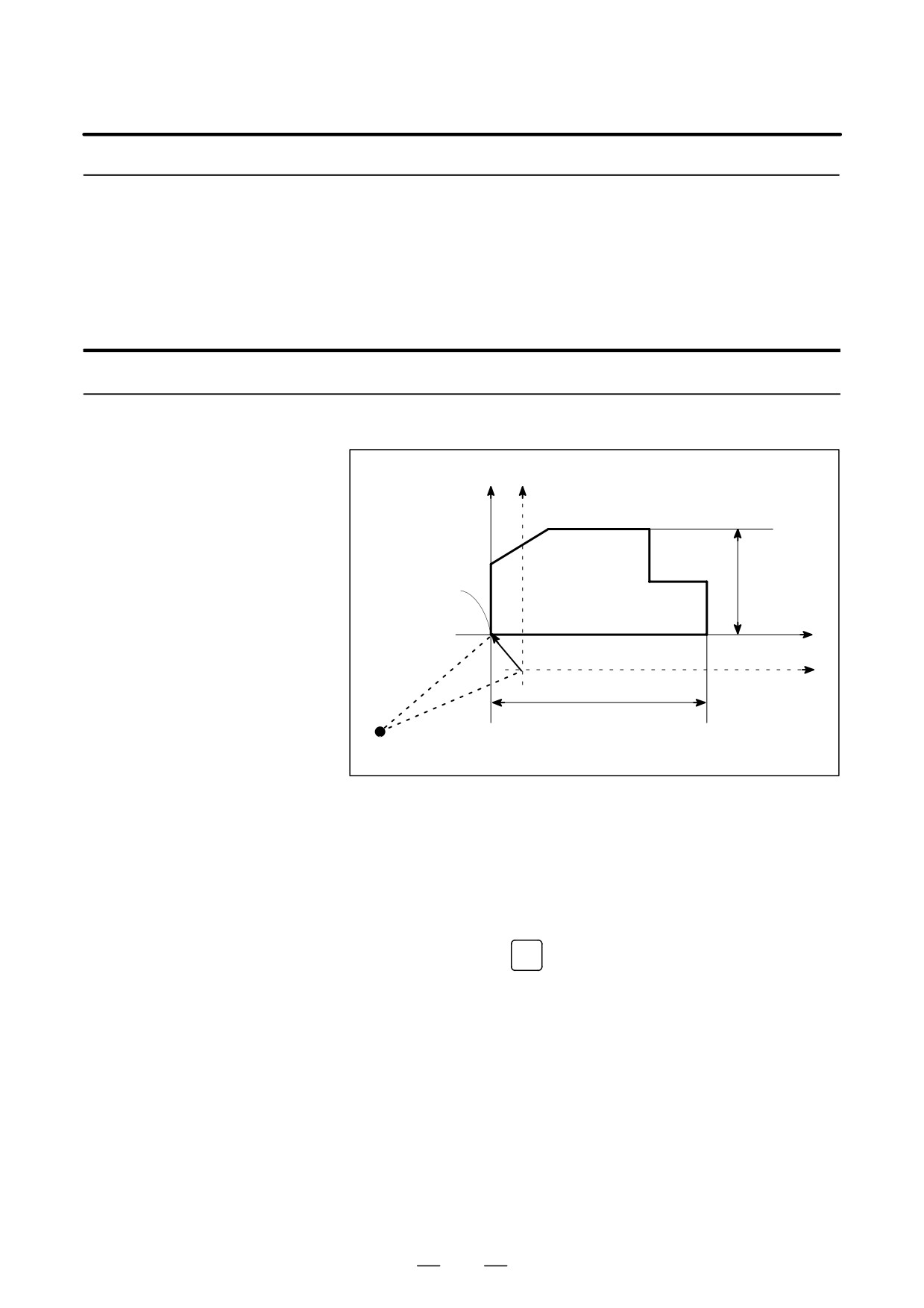
This function is used to compensate for the difference between the
programmed workpiece coordinate system and the actual workpiece
Direct Input of
coordinate system. The measured offset for the origin of the workpiece
Measured Workpiece
coordinate system can be input on the screen such that the command
Origin Offsets
values match the actual dimensions.
Selecting the new coordinate system matches the programmed coordinate
system with the actual coordinate system.
Procedure for Direct Inputting of Measured Workpiece Origin Offsets
Procedure
Y y
Surface A
Programmed
α
workpiece origin
Surface B
O’
X
New offset
O
x
β
Previous
offset
Origin
1
When the workpiece is shaped as shown above, position the reference
tool manually until it touches surface A of the workpiece.
2
Retract the tool without changing the Y coordinate.
3
Measure distance α between surface A and the programmed origin of
the workpiece coordinate system as shown above.
OFFSET
4
Press function key
SETTING
1043

11. SETTING AND DISPLAYING DATA
OPERATION
B-63534EN/02
5
To display the workpiece origin offset setting screen, press the
chapter selection soft key [WORK].
WORK COORDINATES
O1234 N56789
(G54)
NO.
DATA
NO.
DATA
00
X
0.000
02
X
0.000
(EXT) Y
0.000
(G55) Y
0.000
Z
0.000
Z
0.000
01
X
0.000
03
X
0.000
(G54) Y
0.000
(G56) Y
0.000
Z
0.000
Z
0.000
> Z100.
S 0 T0000
MDI **** *** ***
16:05:59
[ NO.SRH ] [ MEASUR ]
[
]
[ +INPUT ] [ INPUT ]
6
Position the cursor to the workpiece origin offset value to be set.
7
Press the address key for the axis along which the offset is to be set
(Y-axis in this example).
8
Enter the measured value (α) then press the [MEASUR] soft key.
9
Move the reference tool manually until it touches surface B of the
workpiece.
10
Retract the tool without changing the X coordinate.
11
Measure distance β then enter the distance at X on the screen in the
same way as in steps 7 and 8.
Limitations
D Consecutive input
Offsets for two or more axes cannot be input at the same time.
D During program
This function cannot be used while a program is being executed.
execution
1044
OPERATION
11. SETTING AND DISPLAYING DATA
B-63534EN/02
11.4.8
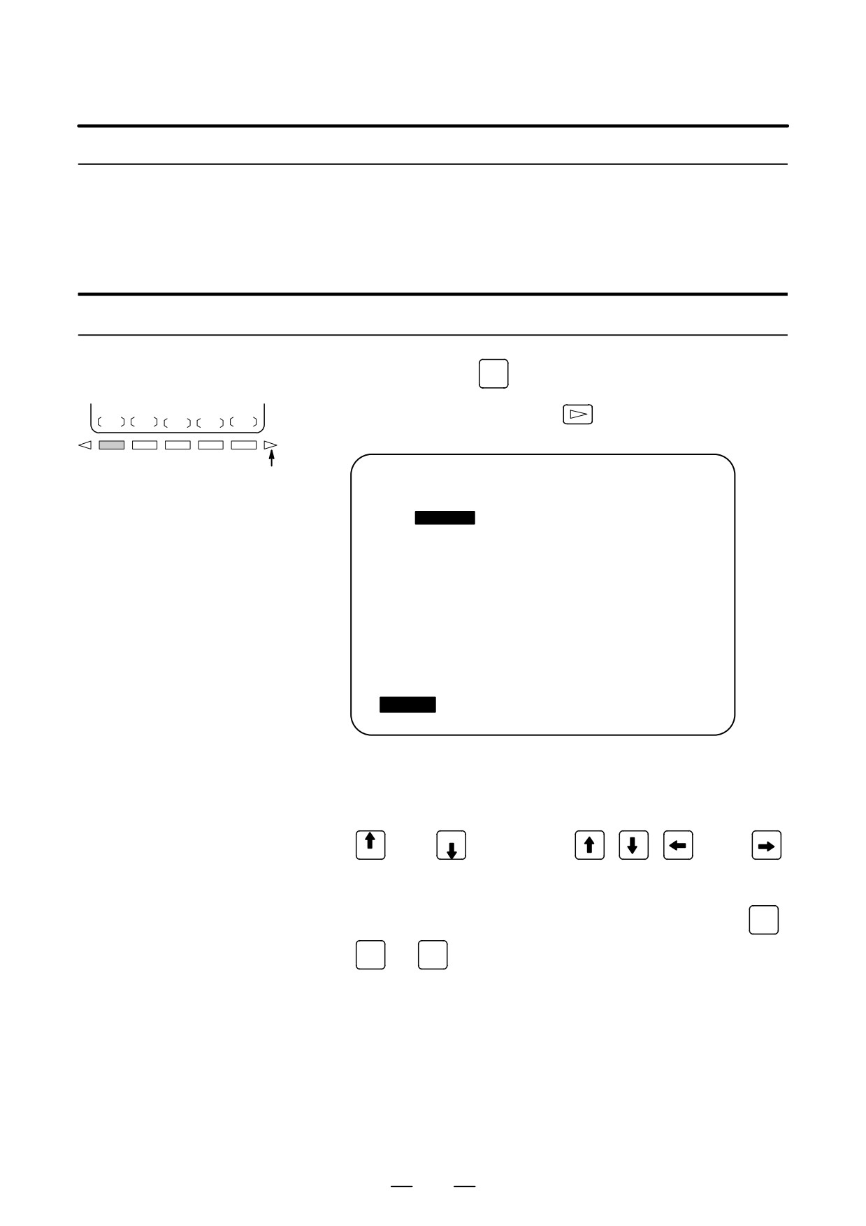
Displays common variables (#100 to #149 or #100 to #199, and #500 to
#531 or #500 to #999) on the CRT. When the absolute value for a common
Displaying and Setting
variable exceeds 99999999, ******** is displayed. The values for
Custom Macro
variables can be set on this screen. Relative coordinates can also be set
Common Variables
to valiables.
Procedure for displaying and setting custom macro common variables
Procedure
OFFSET
1
Press function key
SETTING
2
Press the continuous menu key
, then press chapter selection
MACRO
soft key [MACRO].The following screen is displayed:
Continuous menu key
VARIABLE
O0001 N00000
NO. DATA
NO. DATA
100
1000.000
108
0.000
101
0.000
109
40000.000
102
-50000.000
110
153020.00
103
0.000
111
0001.000
104
1238501.0
112
0.000
105
0.000
113
20000.000
106
0.000
114
0.000
107
0.000
115
0.000
ACTUAL POSITION (RELATIVE)
X
0.000
Y
0.000
Z
0.000
> _
S 0 T0000
MDI **** *** ***
16:05:59
[ NO.SRH
]
[
]
[ INP.C.
]
[
]
[ INPUT ]
3
Move the cursor to the variable number to set using either of the
following methods:
- Enter the variable number and press soft key [NO.SRH].
- Move the cursor to the variable number to set by pressing page keys
and/or PAGE
and cursor keys
,
,
, and/or
PAGE
4
Enter data with numeric keys and press soft key [INPUT].
5
To set a relative coordinate in a variable, press address key
X
,
Y
, or
Z
, then press soft key [INP.C.].
6
To set a blank in a variable, just press soft key [INPUT]. The value
field for the variable becomes blank.
1045
11. SETTING AND DISPLAYING DATA
OPERATION
B-63534EN/02
11.4.9
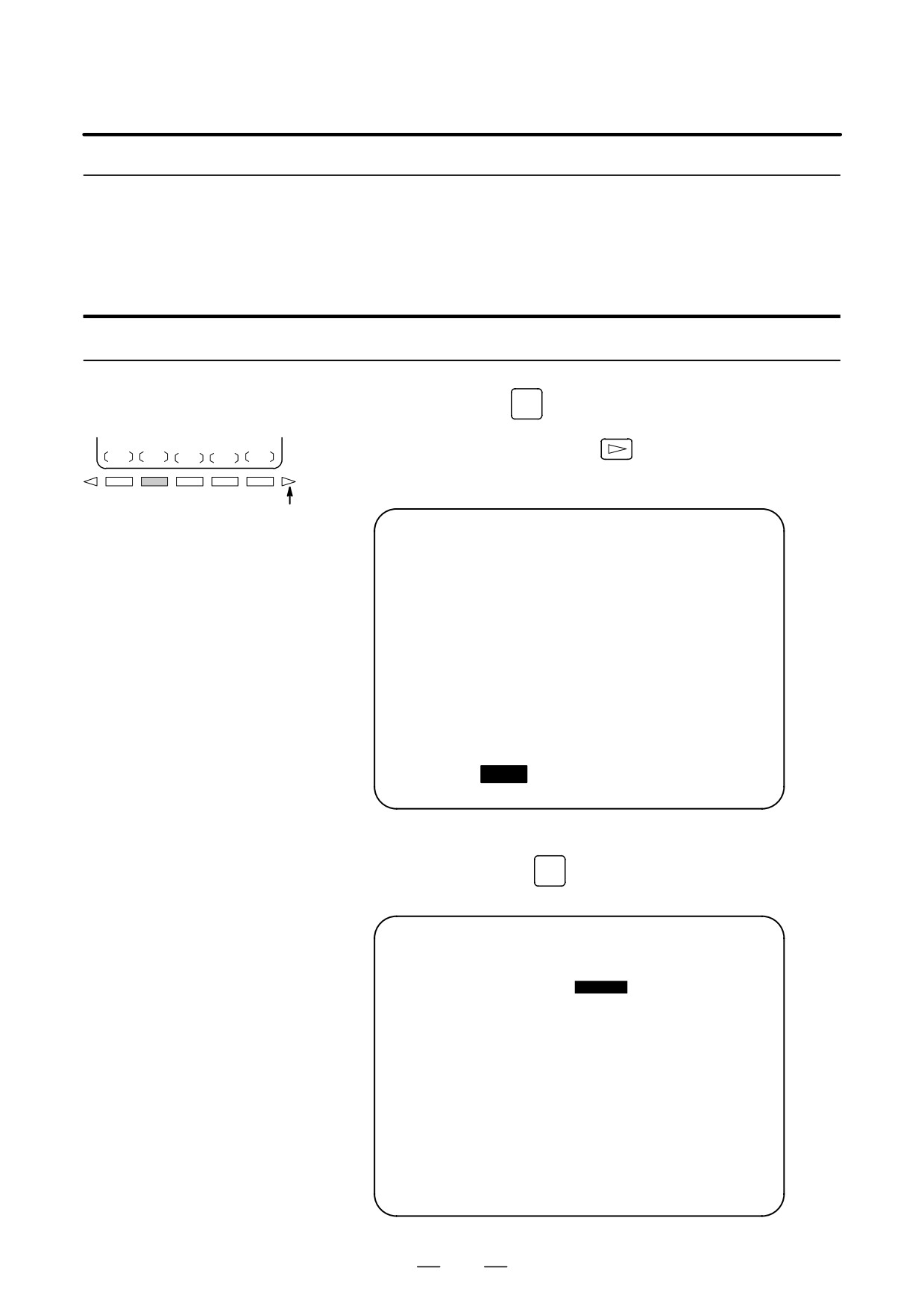
This subsection uses an example to describe how to display or set
machining menus (pattern menus) created by the machine tool builder.
Displaying Pattern
Refer to the manual issued by the machine tool builder for the actual
Data and Pattern Menu
pattern menus and pattern data. See II. PROGRAMMING for the pattern
data entry function.
Procedure for displaying the pattern data and the pattern menu
Procedure
OFFSET
1
Press function key
SETTING
2
Press the continuous menu key
, then press chapter selection
MENU
soft key [MENU].
The following screen (pattern menu screen) is displayed:
Continuous menu key
MENU : HOLE PATTERN
O0000 N00000
1. TAPPING
2. DRILLING
3. BORING
4. POCKET
5. BOLT HOLE
6. LINE ANGLE
7. GRID
8. PECK
9.
10.
> _
MDI **** *** ***
16:05:59
[ MACRO ] [
MENU
]
[ OPR ] [
]
[ (OPRT) ]
3
Enter a pattern number and press soft key [SELECT].
In this example, press
5
, then press [SELECT].
The following screen (pattern data screen) is displayed:
VAR. : BOLT HOLE
O0001 N00000
NO. NAME
DATA COMMENT
500
TOOL
0.000
501
STANDARD X
0.000
*BOLT HOLE
502
STANDARD Y
0.000
CIRCLE*
503
RADIUS
0.000
SET PATTERN
504
S. ANGL
0.000
DATA TO VAR.
505
HOLES NO
0.000
NO.500-505.
506
0.000
507
0.000
ACTUAL POSITION (RELATIVE)
X
0.000
Y
0.000
> _
Z
0.000
MDI **** *** ***
16:05:59
[ OFFSET ] [SETING] [
]
[
]
[ (OPRT) ]
1046
OPERATION
11. SETTING AND DISPLAYING DATA
B-63534EN/02
4
Enter necessary pattern data and press
INPUT
5
After entering all necessary data, enter the MEMORY mode and press
the cycle start button to start machining.
Explanations
D Explanation of the
HOLE PATTERN : Menu title
pattern menu screen
An optional character string can be displayed within 12 characters.
BOLE HOLE : Pattern name
An optional character string can be displayed within 10 characters.
The machine tool builder should program character strings of menu title
and pattern name by custom macro, and load them into the program
memory.
D Explanation of the
BOLT HOLE : Pattern data title
pattern data screen
An optional character string can be displayed within 12 characters.
TOOL : Variable name
An optional character string can be displayed within 10 characters.
BOLT HOLE CIRCLE : Comment statement
An optional character string comment can be displayed up to 12
characters/line by 8 lines.
The machine tool builder should program the character strings of variable
name and comment statement by custom macro, and load them into the
program memory.
1047
11. SETTING AND DISPLAYING DATA
OPERATION
B-63534EN/02
11.4.10
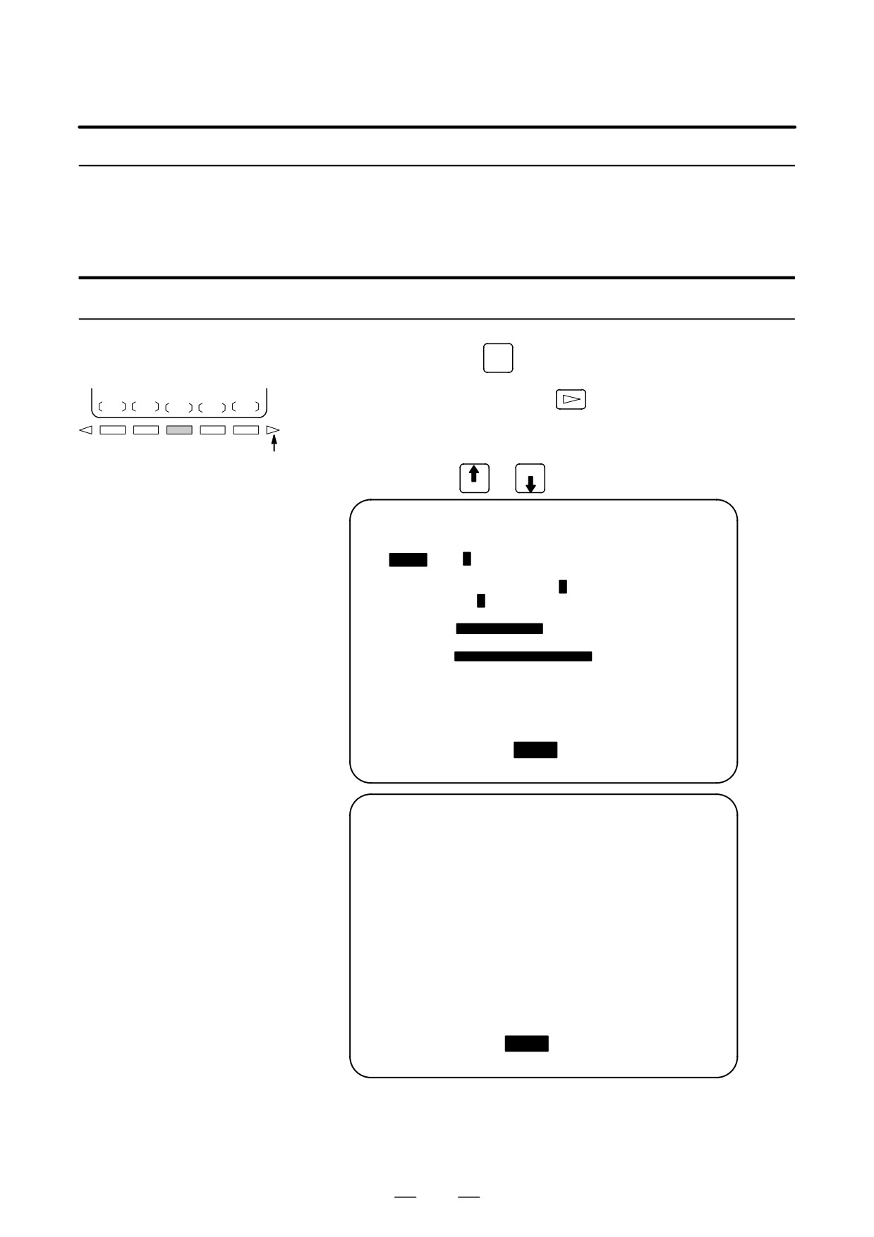
With this function, functions of the switches on the machine operator’s
panel can be controlled from the CRT/MDI panel.
Displaying and Setting
Jog feed can be performed using numeric keys.
the Software
Operator’s Panel
Procedure for displaying and setting the software operator’s panel
Procedure
OFFSET
1
Press function key
SETTING
2
Press the continuous menu key
, then press chapter selection soft
MOPR
key [OPR].
3
The screen consists of several pages.
Continuous menu key
Press page key
or PAGE
until the desired screen is displayed.
PAGE
OPERATOR’S PANEL
O0000 N00000
MODE : MDI
MEM EDIT HNDL JOG REF
STEP MULTI.
:
*1
*10
*100
RAPID OVRD. :
100%
50%
25% F0
JOG FEED
:
2.0%
*************
FEED OVRD. : 100%
***
ACTUAL POSITION (ABSOLUTE)
X
0.000
Y
0.000
Z
0.000
>_
MDI **** *** ***
16:05:59
[ MACRO ] [
]
[
OPR ] [TOOLLF]
[ (OPRT) ]
OPERATOR’S PANEL
O0000 N00000
BLOCK SKIP
:
OFF J ON
SINGLE BLOCK
:
J OFF ON
MACHINE LOCK
:
OFF J ON
PROTECT KEY
:
J PROTECT
RELEASE
FEED HOLD
:
J OFF
ACTUAL POSITION (ABSOLUTE)
X
0.000
Y
0.000
Z
0.000
S 0 T0000
MDI **** *** ***
16:05:59
[ MACRO ] [
]
[
OPR
]
[ TOOLLF ]
[
(OPRT) ]
1048
OPERATION
11. SETTING AND DISPLAYING DATA
B-63534EN/02
4
Move the cursor to the desired switch by pressing cursor key
or
5
Push the cursor move key
or
to match the mark J to an
arbitrary position and set the desired condition.
6
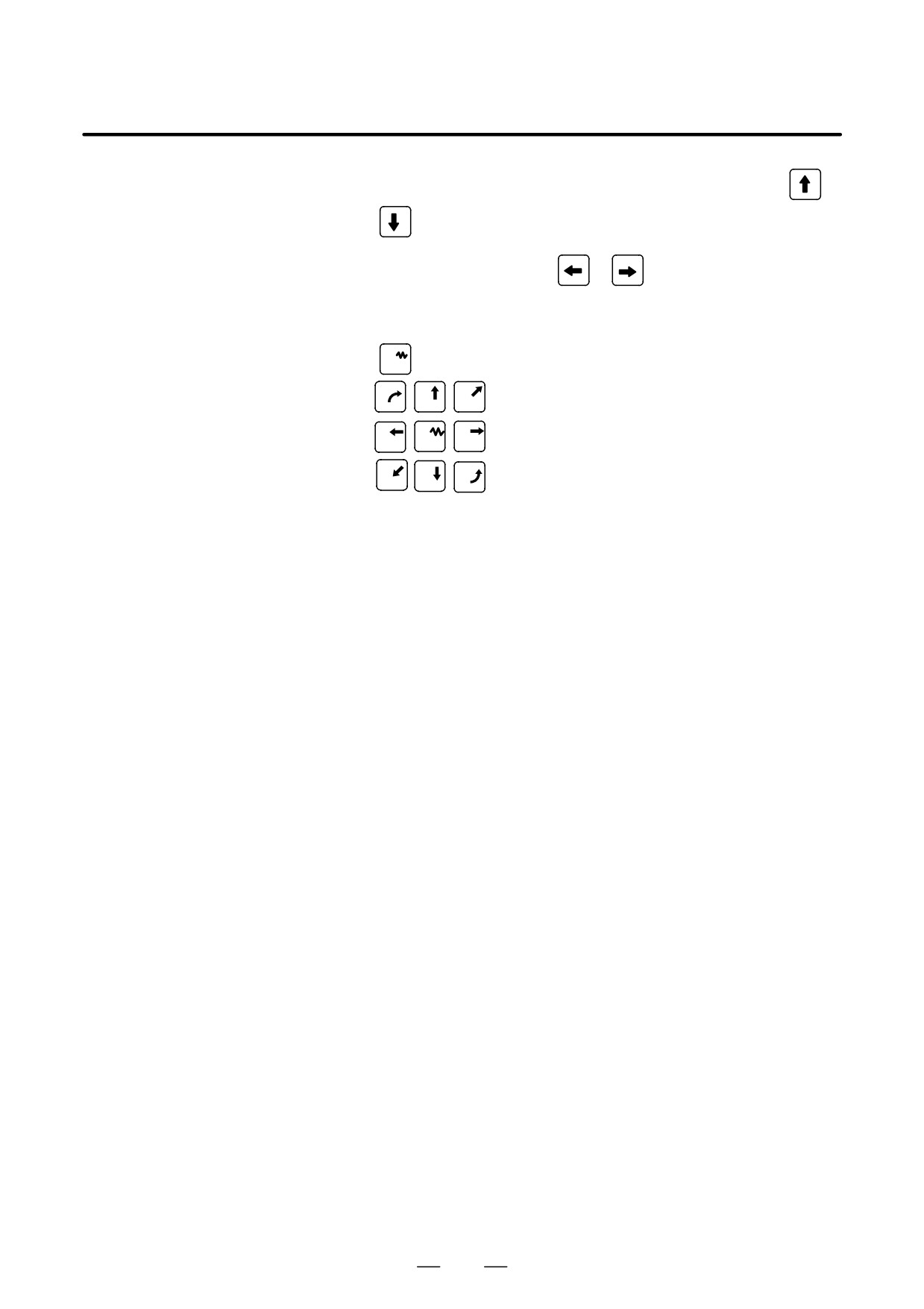
Press one of the following arrow keys to perform jog feed. Press the
5
key together with an arrow key to perform jog rapid traverse.
7
8
9
4
5
6
1
2
3
Explanations
D Valid operations
The valid operations on the software operator’s panel are shown below.
Whether to use the CRT/MDI panel or machine operator’s panel for each
group of operations can be selected by parameter 7200.
Group1 : Mode selection
Group2 : Selection of jog feed axis, jog rapid traverse
Group3 : Selection of manual pulse generator feed axis, selection of
manual pulse magnification x1, x10, x100
Group4 : Jog federate, federate override, rapid traverse override
Group5 : Optional block skip, single block, machine lock, dry run
Group6 : Protect key
Group7 : Feed hold
D Display
The groups for which the machine operator’s panel is selected by
parameter 7200 are not displayed on the software operator’s panel.
D Screens on which jog
When the CRT indicates other than the software operator’s panel screen
feed is valid
and diagnostic screen, jog feed is not conducted even if the arrow key is
pushed.
D Jog feed and arrow keys
The feed axis and direction corresponding to the arrow keys can be set
with parameters (Nos. 7210 to 7217).
D General purpose
Eight optionally definable switches are added as an extended function of
switches
the software operator’s panel. The name of these switches can be set by
parameters (Nos. 7220 to 7283) as character strings of max. 8 characters.
For the meanings of these switches, refer to the manual issued by machine
tool builder.
1049
11. SETTING AND DISPLAYING DATA
OPERATION
B-63534EN/02
11.4.11
Tool life data can be displayed to inform the operator of the current state
of tool life management. Groups which require tool changes are also
Displaying and Setting
displayed.The tool life counter for each group can be preset to an arbitrary
Tool Life Management
value. Tool data (execution data) can be reset or cleared. To register or
Data
modify tool life management data, a program must be created and
executed. See Explanations in this section for details.
When bit 6 (EXT) of parameter 6801 is 1, extended tool life management
applies. See III-11.4.12.
Procedure for display and setting the tool life management data
Procedure
OFFSET
1
Press function key
SETTING
TOOLLF
2
Press the continuous menu key
to display chapter selection soft
key [TOOLLF].
3
Press softkey [TOOLLF].
4
One page displays data on two groups. Pressing page key
PAGE
or
successively displays data on the following groups. Up
PAGE
to four group Nos., for which the Tool Change signal is being issued,
are displayed at the bottom of each page. An arrow shown in the
figure is displayed for five or more groups, if exists.
TOOL LIFE DATA :
O3000 N00060
SELECTED GROUP 000
GROUP 001 : LIFE
0150 COUNT
0000
0034
0078
0012
0056
0090
0035
0026
0061
0000
0000
0000
0000
0000
0000
0000
0000
GROUP 002 : LIFE
1400 COUNT
0000
0062
0024
0044
0074
0000
0000
0000
0000
0000
0000
0000
0000
0000
0000
0000
0000
TO BE CHANGED : 003 004 005 006 --->
> _
MEM **** *** ***
16:05:59
[ MACRO ] [
] [ OPR
] [ TOOLLF
] [ (OPRT) ]
1050
OPERATION
11. SETTING AND DISPLAYING DATA
B-63534EN/02
5
To display the page containing the data for a group, enter the group
number and press soft key [NO.SRH].
The cursor can be moved to an arbitrary group by pressing cursor key
or
6
To change the value in the life counter for a group, move the cursor to
the group, enter a new value (four digits), and press [INPUT]. The life
counter for the group indicated by the cursor is preset to the entered
value. Other data for the group is not changed.
7
To reset the tool data, move the cursor on the group to reset, then press
the [(OPRT)], [CLEAR], and [EXEC] soft keys in this order.
All execution data for the group indicated by the cursor is cleared
together with the marks (@, #, or *).
1051
11. SETTING AND DISPLAYING DATA
OPERATION
B-63534EN/02
Explanations
D Display contents
TOOL LIFE DATA :
O3000 N00060
SELECTED GROUP 000
GROUP 001 : LIFE
0150 COUNT
0007
0034
#
0078
@
0012
0056
0090
0035
0026
0061
0000
0000
0000
0000
0000
0000
0000
0000
GROUP 002 : LIFE
1400
COUNT
0000
0062
0024
0044
0074
0000
0000
0000
0000
0000
0000
0000
0000
0000
0000
0000
0000
TO BE CHANGED : 003 004 005 006 --->
> _
MEM **** *** ***
16:05:59
[ MACRO ] [
] [ OPR
] [ TOOLLF ][ (OPRT) ]
S
The first line is the title line.
S
In the second line the group number of the current command is
displayed.
When there is no group number of the current command, 0 is displayed.
S
In lines 3 to 7 the tool life data of the group is displayed.
The third line displays group number, life and the count used.
The life count is chosen by parameter LTM (No. 6800#2) as either
minutes(or hours) or number of times used.
In lines 4 to 5, tool numbers are displayed. In this case, the tool is
selected in the order, 0034 → 0078 → 0012 → 056 → 0090 ...
The meaning of each mark before the tool numbers is :
* : Shows the life has finished.
# : Shows that the skip command has been accepted.
@ : Shows that the tool is currently being used.
The life counter counts for tool with @.
“*” is displayed when the next command is issued by the group to
which it belongs.
S
Lines 8 to 12 are next group life data to the group displayed in lines 3
to 7.
S
In the thirteenth line the group number when the tool change signal is
being emitted is displayed. The group number display appears in
ascending order. When it cannot be completely displayed, “--->” is
displayed.
1052
OPERATION
11. SETTING AND DISPLAYING DATA
B-63534EN/02
11.4.12
The extended tool life management function provides more detailed data
display and more data editing functions than the ordinary tool life
Displaying and Setting
management function.
Extended Tool Life
Moreover, if the tool life is specified in units of time, the time which has
Management
been set can be increased or reduced (life count override).
When bit 6 (EXT) of parameter 6801 is set to 0, the ordinary tool life
management function applies. See III-11.4.11.
Procedure for displaying and Setting extended tool life management
Procedure
OFFSET
1
Press function key
SETTING
2
Press the continuous menu key
to display chapter selection soft
NO.SRH
CLEAR
EDIT
(OPRT)
key [TOOLLF].
3
Press soft key [TOOLLF] to display the tool life management data
Continuous menu key
screen.
On this screen, place the cursor on a group of items to be edited.
4
Press soft key [(OPRT)].
5
Press soft key [EDIT].
The extended tool life management data editing screen for the group
indicated by the cursor is the displayed.
LIFE DATA EDIT GROUP : 001 O0010 N00001
TYPE
:
1 (1:C 2:M)
NEXT GROUP: ***
LIFE
:
9800
USE GROUP : ***
COUNT
:
6501
SELECTED GROUP : 001
NO. STATE
T-CODE
H-CODE
D-CODE
01
0034
011
005
02
#
0078
000
033
03
@
0012
004
018
04
0056
000
000
05
0090
000
000
06
0076
023
012
> _
MDI **** *** ***
16:05:59
[ INSERT ]
[ DELETE ]
[ STATE ]
[ END ]
[ INPUT ]
Tool life management data can be edited as follows:
6
Select the MDI mode.
7
Stop, pause, or reset the CNC by the feed hold, single block stop, or
reset operation (tool life management data cannot be edited while data
is set by a program.).
The following editing can be performed. See each step for details:
⋅
Setting the life count type, life value, current life count,
and tool data (T, H, or D code) :
7-1
⋅
Adding a tool group :
7-2
⋅
Adding a tool number (T code) :
7-3
1053
11. SETTING AND DISPLAYING DATA
OPERATION
B-63534EN/02
⋅
Deleting a tool group :
7-4
⋅
Deleting tool data (T, H, or D code) :
7-5
⋅
Skipping a tool :
7-6
⋅
Clearing the life count
(resetting the life) :
7-7
7-1
Setting the life count type, life value, current life count, and tool
data (T, H, or D code)
(1) Position the cursor on the data item to be changed.
(2) Enter a desired value.
(3) Press the softkey [INPUT].
7-2
Adding a tool group
(1) In step 3, select a group for which no data is set and display the
editing screen.
(2) Enter tool numbers.
(3) Press soft key [INSERT].
⋅ In this case, the type of the life counter is determined by the setting of
LTM (No. 6800#2), and 0 is set in both the life expectancy and life
counter.
⋅
0 is set in both the H code and D code.
⋅ The cursor remains on the tool number until the T code is specified.
7-3
Adding a tool number
(1) Move the cursor to the tool data (T, H, or D code) after which a new
number is to be added.
(2) Enter the tool number.
(3) Press soft key [INSERT].
Example),Inserting tool No. 1500 between No. 1 and No. 2.
NO. STATE T-CODE
H-CODE
D-CODE
01
0034
11
5
02
#
0078
0
33
Move the cursor to 5 in D-CODE column and press soft key
[INSERT].
NO. STATE T-CODE
H-CODE
D-CODE
01
0034
11
5
02
1500
0
0
03
#
0078
0
33
1054
OPERATION
11. SETTING AND DISPLAYING DATA
B-63534EN/02
7-4
Deleting a tool group
(1) In step 3, position the cusor on a group to be deleted and display the
editing screen.
(2) Press soft key [DELETE].
(3) Press soft key [GROUP].
(4) Press soft key [EXEC].
7-5
Deleting tool data (T, H, or D code)
(1) Position the cursor on the data item (T, H, or D code) to be
deleted.
(2) Press soft key [DELETE].
(3) Press soft key [<CRSR>].
⋅ The line containing the cursor is deleted.
⋅ When a tool with mark @ (being used) is deleted, mark @ shifts to the
tool whose life has expired most recently or which has been skipped.
In this case, marks * and # are displayed in reverse video.
q
:
7-6
Skipping a tool
(1) Position the cursor on the data item (T, H, or D code) for the tool to
be skipped.
(2) Press soft key [STATE].
(3) Press soft key [SKIP].
7-7
Clearing the life count (resetting the life)
(1) Position the cursor on the data item (T, H, or D code) of the tool to be
cleared.
(2) Press soft key [STATE].
(3) Press soft key [CLEAR].
8
To complete the edit operation, press soft key [END].
The tool life management screen is displayed again.
1055
11. SETTING AND DISPLAYING DATA
OPERATION
B-63534EN/02
Explanations
D Displays
LIFE DATA EDIT
GROUP : 001 O0010 N00001
TYPE
:
1 (1:C 2:M)
NEXT GROUP: ***
LIFE
:
9800
USE GROUP : ***
COUNT
:
6501
SELECTED GROUP : 001
NO. STATE T-CODE
H-CODE
D-CODE
01
0034
011
005
02
#
0078
000
033
03
@
0012
004
018
04
0056
000
000
05
0090
000
000
06
0076
023
012
> _
MDI **** *** ***
16:05:59
[ INSERT ] [ DELETE ] [ STATE ] [ END ]
[ INPUT ]
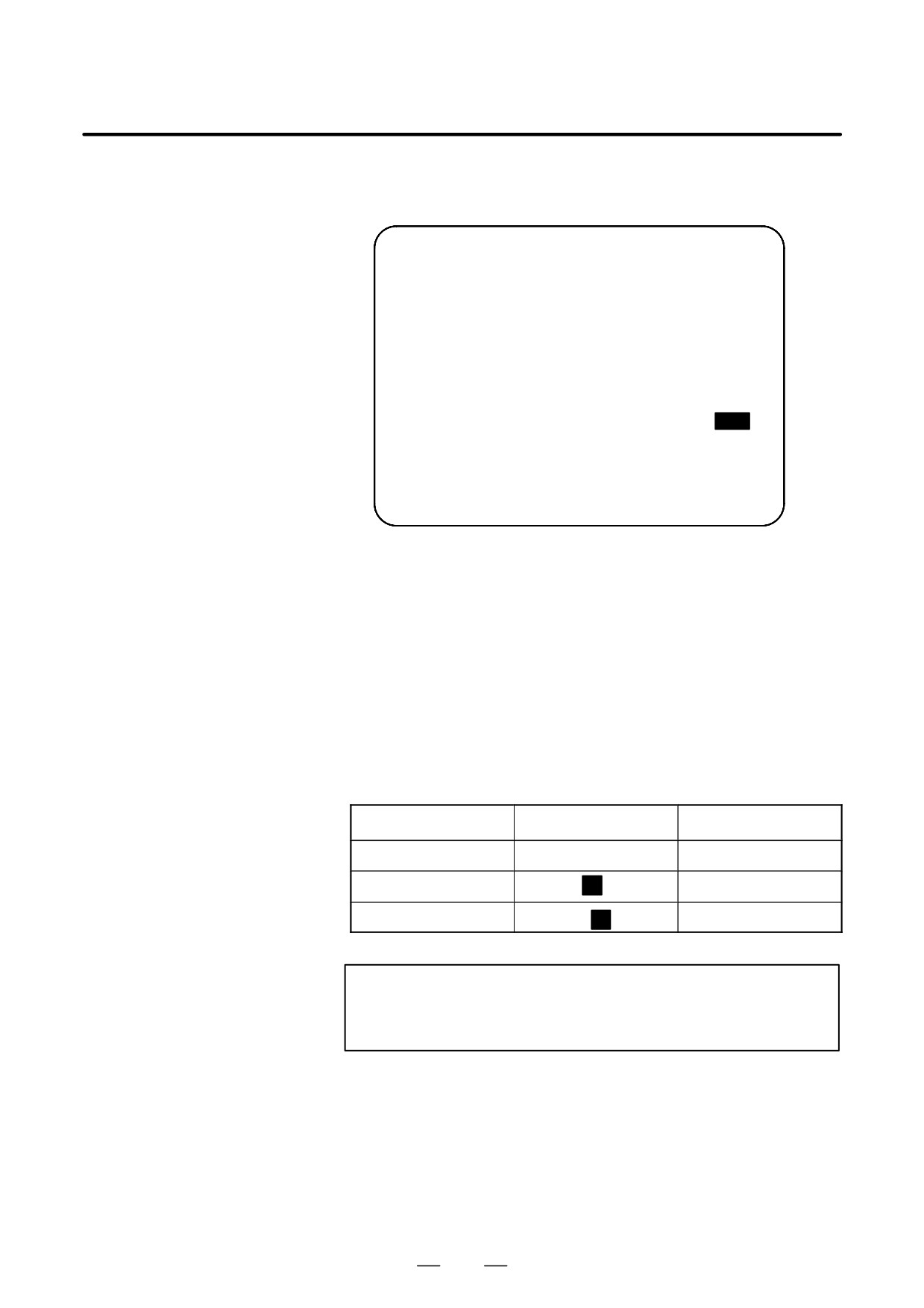
NEXT GROUP :
Number of the tool group whose life is to be calculated by the next M06
command
USE GROUP :
Number of the tool group whose life is being calculated
SELECTED GROUP :
Number of the tool group whose life is being calculated or was calculated
last
TYPE: 1: Life count is represented in units of cycles.
TYPE: 2 : Life count is represented in units of minutes.
LIFE : Life expectancy
COUNT : Life counter
STATE : State of the tool
Tool state
In use
Not in use
Available
@
_(Space)
Skip
#
q
Skipped
w /
:
(Note)
:
NOTE
When bit 3 (EMD) of parameter 6801 is set to 0, @ is
displayed until the next tool is selected.
T-CODE : Tool number
H-CODE : H code
D-CODE : D code
1056
OPERATION
11. SETTING AND DISPLAYING DATA
B-63534EN/02
D Tool life management
When the extended tool life management function is provided, the
screen
following items are added to the tool life management screen:
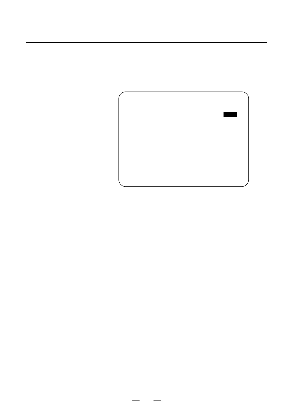
S NEXT: Tool group to be used next
S USE: Tool group in use
S Life counter type for each tool group (C: Cycles, M: Minutes)
TOOL LIFE DATA
O0001 N00001
NEXT
***
USE
***
SELECTED GROUP : 001
GROUP
001 : C
LIFE
9800
COUNT 6501
*0034
#0078
@0012
*0056
0090
*0076
GROUP
002 : C
LIFE
9800
COUNT 1001
*0011
#0022
*0201
*0144
*0155
#0066
0176
0188
0019
0234
0007
0112
0156
0090
0016
0232
TO BE CHANGED :
006
012
013
014
--->
> _
S 0 T0000
MDI **** *** ***
16:05:59
[ NO.SRH ] [
]
[ CLEAR ] [ EDIT ]
[ INPUT ]
D Life count override
The tool life count can be overridden provided that the life counter is
indicated in units of minutes and LFV (bit 2 of parameter 6801) is 1.
Override values can be specified using the override switch on the
operator’s panel within the range from 0 to 99.9. If 0 is specified, tool life
is not counted. If the count of actual cutting time is less than 4 seconds,
the override value is invalid.
Example
When cutting is performed for 10 minutes with an override of 0.1, the tool
life counter counts one minute.
D Display of the mark
The symbol * for indicating that the life of a tool has expired can be
indicating that the life of
displayed either when the machine starts using the next tool or when the
a tool has expired
life of the tool actually expires. Either of these methods can be selected
using EMD (bit 3 of parameter 6801).
D Influence of changes in
S Modification of the life expectancy or life counter does not affect the
data
tool states or tool change signal.
S When the type of the life counter is changed, be sure to change the life
expectancy and life count as well.
1057
11. SETTING AND DISPLAYING DATA
OPERATION
B-63534EN/02
11.4.13
Chopping data, including the reference point (R point), upper dead point,
lower dead point, and chopping feedrate, can be displayed and set by
Displaying and Setting
using the chopping screen.
Chopping Data
Procedure for displaying and setting chopping data
Procedure
OFFSET
1
Press the
SETTING
function key.
2
Press the continuous menu key
several times until [CHOP] is
CHOP
displayed.
3
Press the [CHOP] soft key.
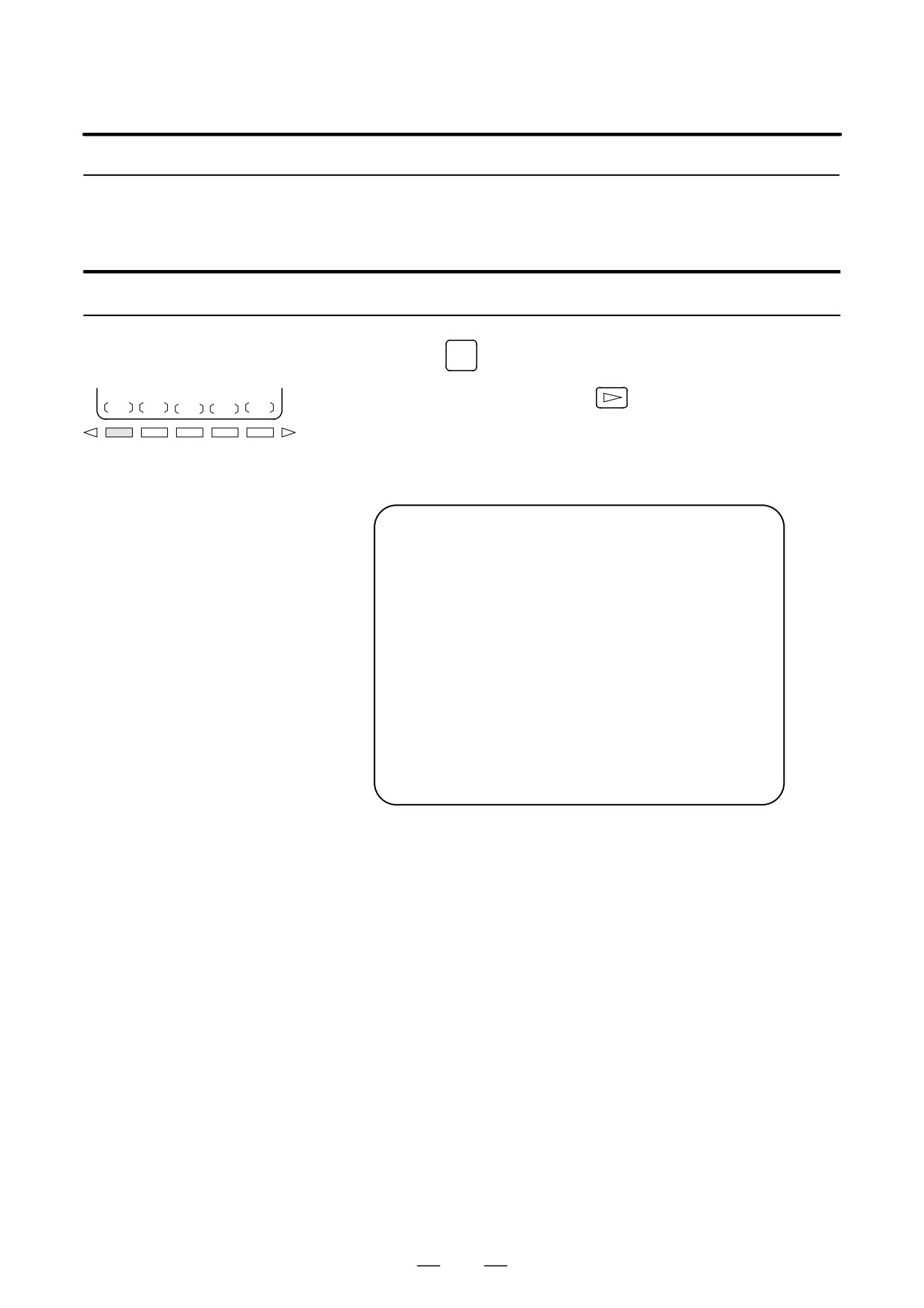
The following chopping screen appears:
CHOPPING PARAMETER
O1000 N10000
R (REFERENCE) POINT =
50.000
UPPER DEAD POINT
=
40.000
LOWER DEAD POINT
=
10.000
CHOPPING FEED RATE
=
2000
> _
MDI
**** *** ***
22:07:08
[
]
[
]
[ TEACH ] [ +INPUT ]
[ INPUT ]
Explanations
D Numerical input
D Position the cursor to the item to be set.
D Enter data, then press the [INPUT] soft key.
D To append the entered data to the current data, press the [+INPUT] soft
key.
The set data is displayed.
D Teaching the position
The reference point (R point), upper dead point, and lower dead point can
be set by teaching the current position (absolute coordinates).
D Move the current position (absolute coordinates) along the chopping
axis to the position to be taught.
D Position the cursor to the item to be set.
D Press the [TEACH] soft key, then the [EXEC] soft key.
The current position (absolute coordinates) is set for that item.
D G81.1
The data for each item displayed on the chopping screen can also be
changed by executing a G81.1 command.
1058
OPERATION
11. SETTING AND DISPLAYING DATA
B-63534EN/02
Limitations
D Chopping feedrate
If bit 7 (CHPX) of parameter No. 8360 is set to 1, the chopping feedrate
cannot be set by using the chopping screen.
The chopping screen can be used to set chopping data regardless of the
D Data setting conditions
current mode, even during automatic or manual operation that includes
chopping. If the level of memory protection signal KEY2 (G046#4) is
currently low, however, chopping data cannot be set.
11.4.14
To enable measurement of the tool length, the following functions are
supported: automatic measurement of the tool length by using a program
Tool Length/Workpiece
command (G37) (automatic tool length measurement, described in
Origin Measurement B
Section II.14.2) and measurement of the tool length by manually moving
the tool until it touches a reference position, such as the workpiece top
surface (tool length measurement, described in Subsection III.11.4.2). In
addition to these functions, tool length/workpiece origin measurement B
is supported to simplify the tool length measurement procedure, thus
facilitating and reducing the time required for machining setup. This
function also facilitates the measurement of the workpiece origin offsets.
This function allows the operator to specify T/M code commands or
reference position return, by means of a manual numeric command, while
the tool length offset measurement screen is displayed.
Procedure for measuring the tool length offset value
The tool length offset value can be measured by manually moving the tool
until it touches the workpiece or a reference block. For details of this
operation, refer to the manual supplied by the machine tool builder.
Procedure
1
Move the tool to the tool change position by means of manual
reference position return, for example.
MODE
2
Press mode selection switch HANDLE or JOG.
EDIT
MEMORY
REMOTE
MDI
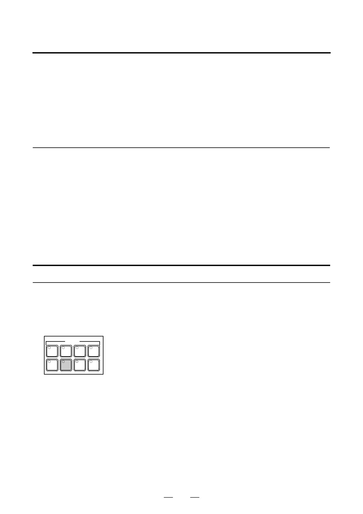
3
Set the tool offset value measurement mode switch on the machine
operator’s panel to ON. The tool length offset measurement screen,
HANDLE
JOG
ZERO
TEACH
RETURN
shown below, appears and ”OFST” blinks in the status display at the
bottom of the screen.
The tool length offset measurement screen varies slightly depending
on whether tool length offset memory A, B (geometry compensation
and wear compensation are treated differently), or C (geometry
compensation and wear compensation are treated differently, and
cutter compensation and tool length compensation are treated
differently) is used.
1059