FANUC Series 16i/160i/160is-MB, Series 18i/180i/180is-MB5, Series 18i/180i/180is-MB. Operator's Manual - page 34
9. EDITING PROGRAMS
OPERATION
B-63534EN/02
9.10
For a 2-path control CNC, setting bit 0 (PCP) of parameter No. 3206 to
1 enables the copying of a specified machining program from one path to
COPYING A
another. Single-program copy and specified-range copy are supported.
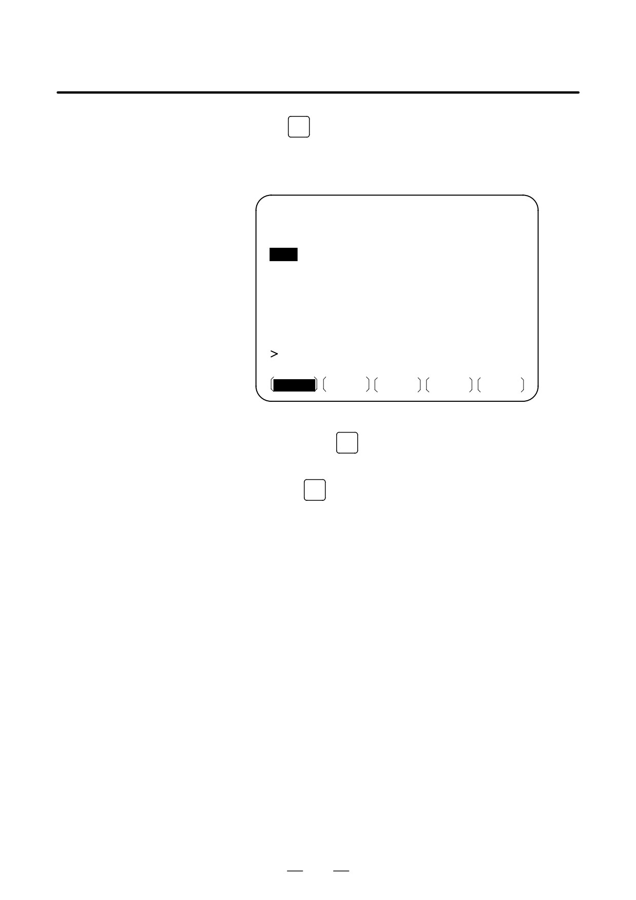
PROGRAM
BETWEEN TWO
PATHS
Procedure for copying a program between two paths
Procedure
1
Select EDIT mode for both paths.
2
Press function key
PROG
3
Press soft key [(OPRT)].
4
Press soft key [P COPY].
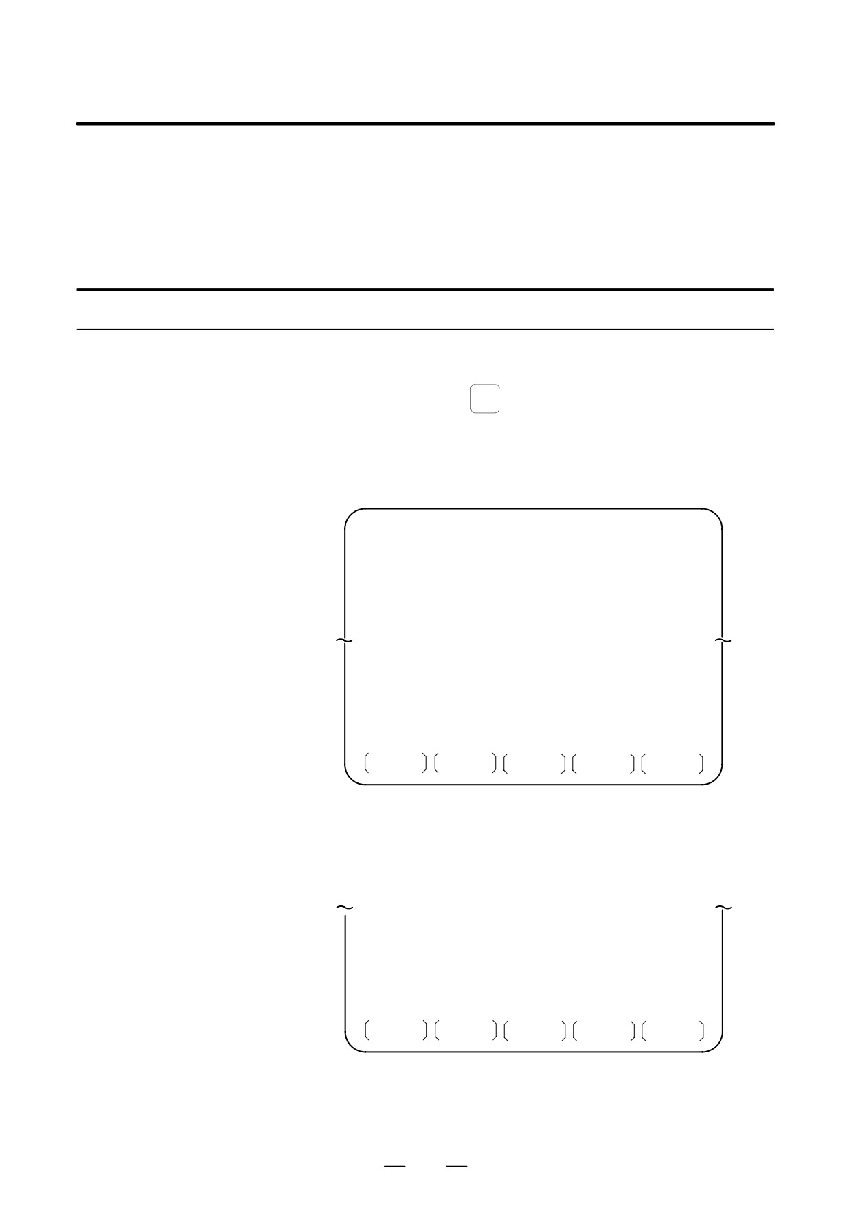
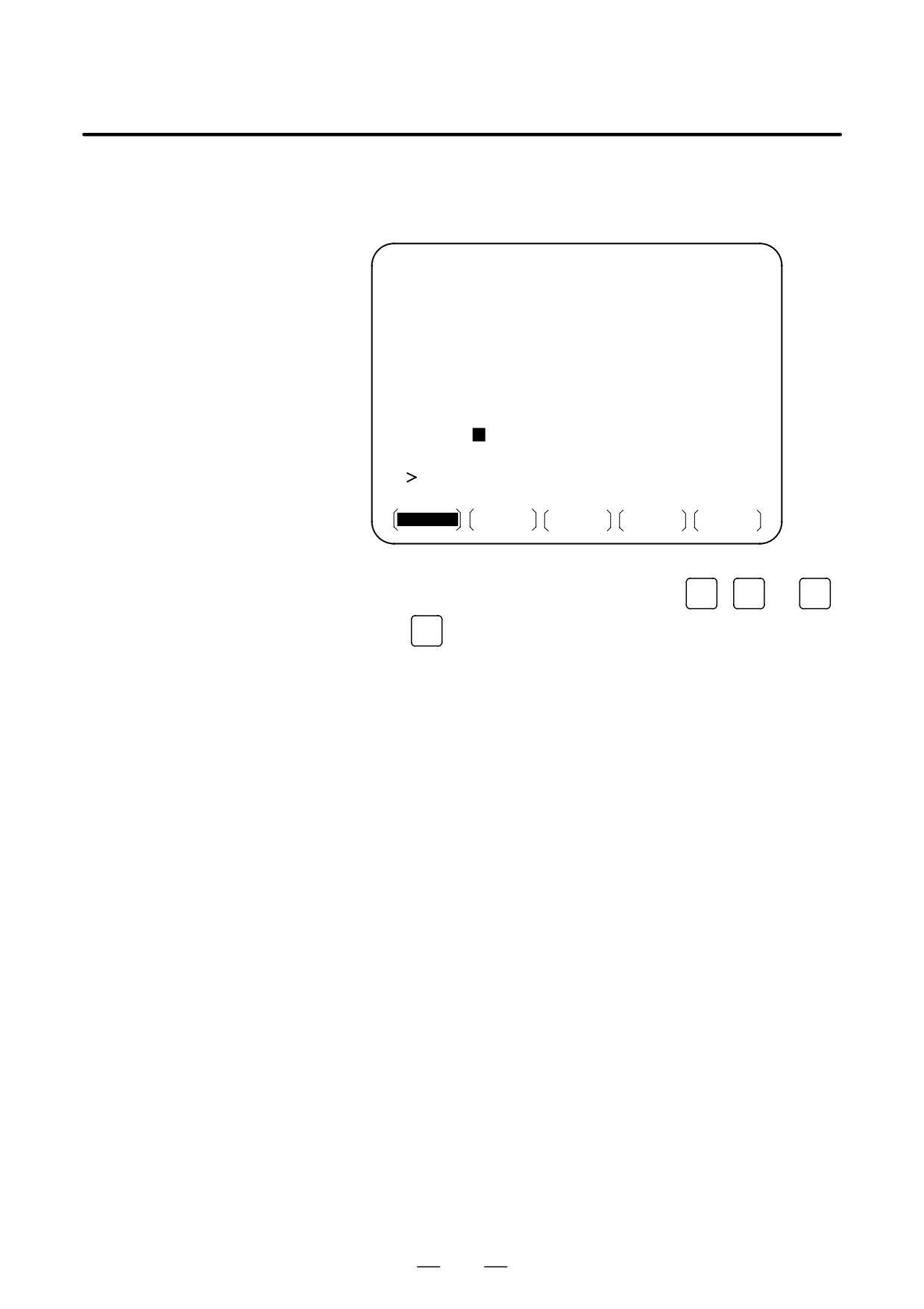
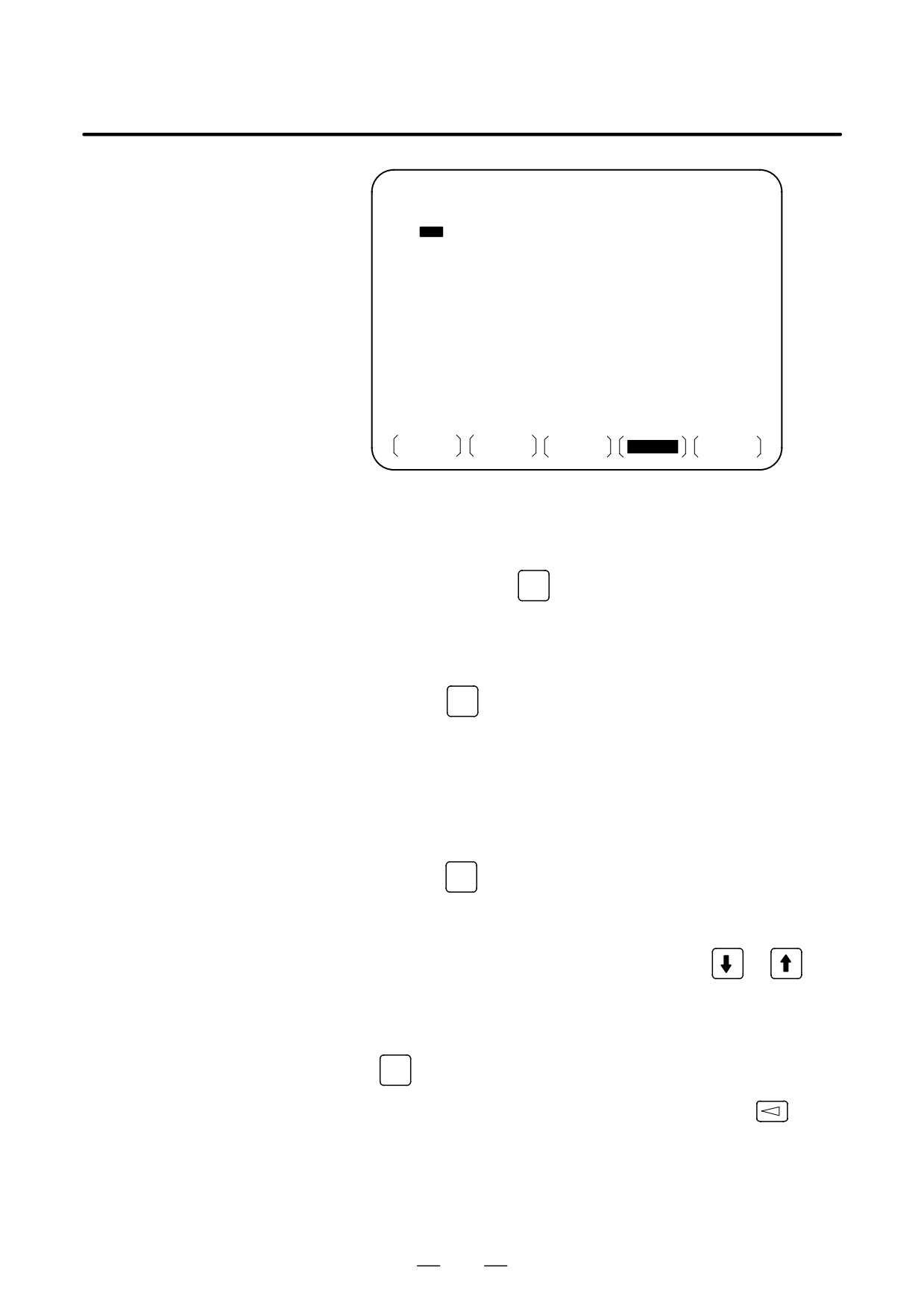
The following soft keys appear:
PROGRAM
O1357
N00130
O1357 (HEAD-1
MAIN PROGRAM) ;
N010 G90 G00 X200.0 Z220.0 ;
N020 T0101 ;
N030 S30000 M03 ;
N040 G40 G00 X40.0 Z180.0 ;
N080 X100.0 Z80.0 ;
N090 Z60.0 ;
N100 X140.0 Z40.0 ;
>_
EDIT
****
***
***
14:25:36
HEAD1
PATH1
PATH2
CAN
5
Press soft key [PATH1] or [PATH2] to select the path from which a
program is to be copied.
(Example) Pressing soft key [PATH1] causes an operation guidance,
shown below, to appear on the screen.
SOURCE : PATH1 =1357
DEST : PATH2
=
REPLACE
: OFF
>_
EDIT
****
***
***
14:25:36
HEAD1
SOURCE
DEST
REPLACE
CAN
EXEC
⋅
First, the program currently selected for the copy source path is
displayed as the program to be copied. If no program has been
selected for the copy source path, ”0000” is displayed.
970
B-63534EN/02
OPERATION
9. EDITING PROGRAMS
6
Select one or more programs to be copied.
⋅
Single-program copy
(1) Enter the number of the program to be copied.
→ ”
”
(2) Press soft key [SOURCE] to set the number.
→ SOURCE:PATH?=”
”
⋅
Specified-range copy
(1) Enter the range of the programs to be copied, as a number.
→ ”
-VVVV”
Range symbol
[Entry format]
-VVVV
Range end (largest) number
Range start (smallest) number
(2) Press soft key [SOURCE] to set the number.
→ SOURCE:PATH?=”
-VVVV”
⋅
To cancel the selection of the program(s) to be copied, press
[SOURCE] again.
7
Select the copy destination number.
The selected program(s) can be copied by assigning numbers other
than their original numbers.
(1) Type the destination number.
→ ”∆∆∆∆”
(2) Press soft key [DEST] to set the number.
→ DEST:PATH?=”∆∆∆∆”
⋅
Pressing [DEST] without entering any number causes the original
program number(s) to be used as is.
⋅
To cancel the set number, press [DEST] again.
⋅
For specified-range copy, the set number is assigned to the first
program of the specified range. The subsequent programs are
assigned numbers obtained by repeatedly incrementing the set
number by one.
8
Specify replacement.
If any number to be assigned to a program to be copied is already
being used for a program registered for the destination path, specify
whether the existing program is to be replaced with that to be copied.
If replacement is currently disabled, pressing soft key [REPLACE]
enables replacement. Pressing
[REPLACE] repeatedly toggles
between replacement being enabled and disabled.
”REPLACE=ON” indicates that replacement is enabled.
”REPLACE=OFF” indicates that replacement is disabled.
9
Press soft key [EXEC] to start copying.
971
9. EDITING PROGRAMS
OPERATION
B-63534EN/02
Explanations
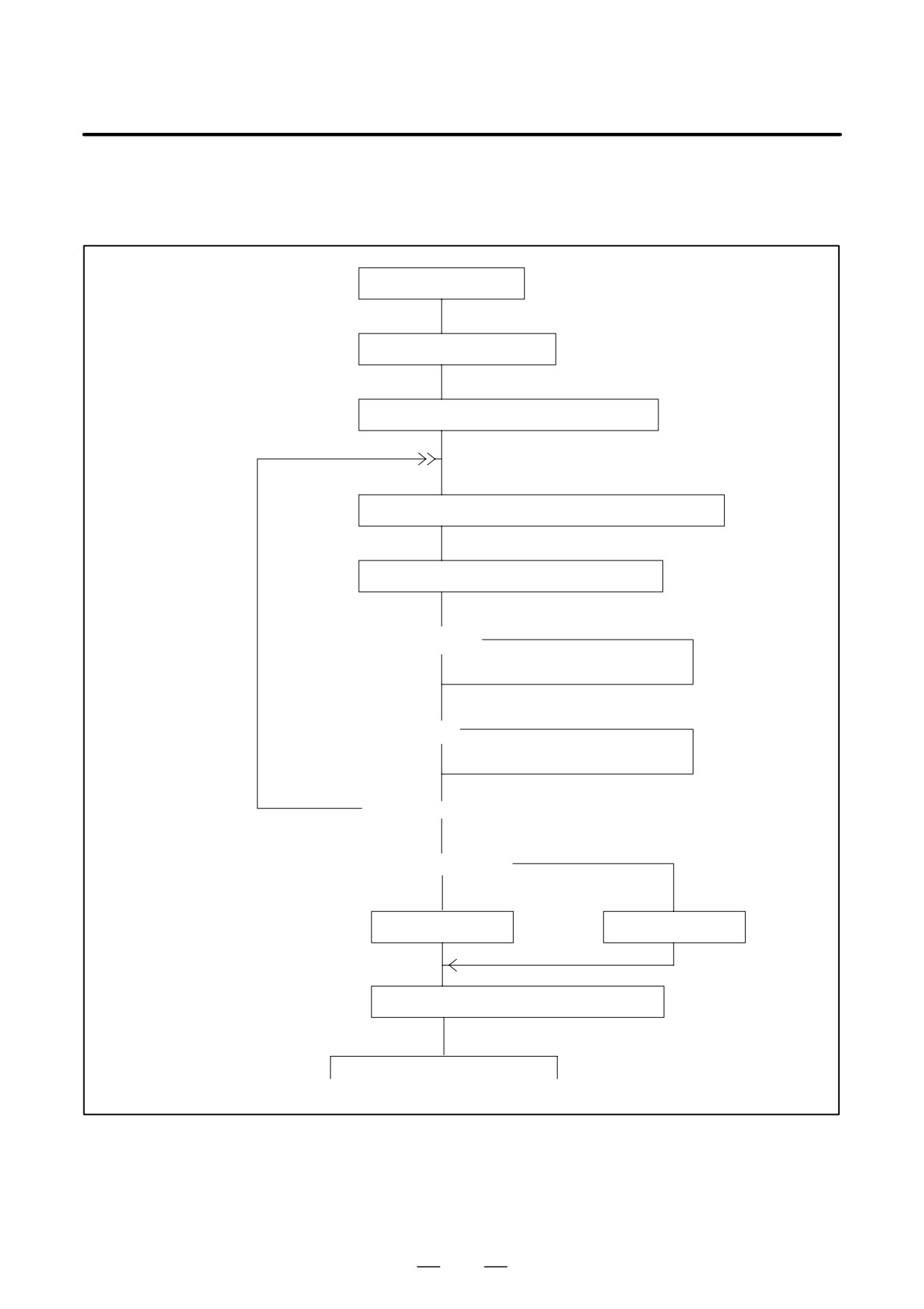
D Operation flow
Program screen
Edit mode/BG edit mode
Set the data protection key to ON (enable editing)
Soft key for starting setting for copy between paths [P COPY]
Copy source selection soft key [PATH1] or [PATH2]
Not set (selected O number)
<”SOURCE” set?>
Set
Not set (selected O number)
<”DEST” set?>
Set
Yes
<Operation cancel soft key [CAN]?>
No
<Replacementsetting?>
To be replaced
Not to be replaced
REPLACE=ON
REPLACE=OFF
Start copying: soft key [EXEC]
Copy completed
Alarm termination
D Background editing
Copying can also be performed during background editing.
972
B-63534EN/02
OPERATION
9. EDITING PROGRAMS
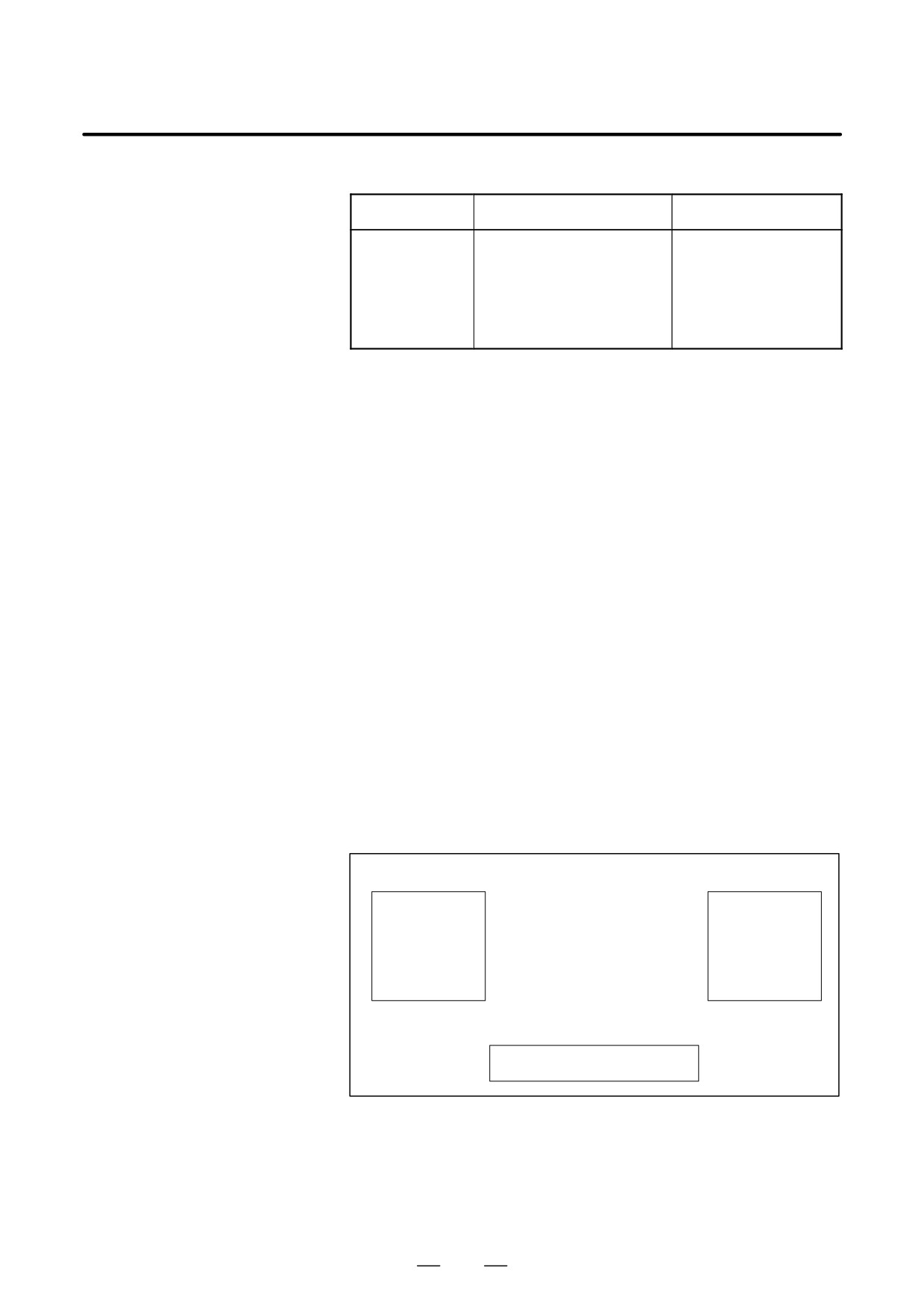
D Major related alarms
Major related alarm numbers
Alarm number
Description
Relevant path
P/S 70,70 BP/S0
Insufficient free memory
Copy destination
P/S 71,71 BP/S
Specified program not found
Copy source
P/S 72,72 BP/S
Too many programs
Copy destination
P/S 73,73 BP/S
Duplicate registration
Copy destination
P/S 75,75 BP/S
Protected program number
Copy source/destination
⋅
BP/S indicates an alarm output during background editing.
⋅
Each alarm is issued to the path for which the operation causing the
alarm is being performed.
Restrictions
D Conditions under which
Copying is not performed under any of the following conditions:
copying cannot be
⋅
The data protection key for the copy destination path is set to OFF.
performed
⋅
The specified O number is protected.
⋅
The specified O number is already being used for a program registered
for the copy destination path (if replacement is disabled).
⋅
The part program storage for the copy destination path does not have
sufficient free space.
⋅
The copy source or destination path is placed in the alarm state.
During background editing, however, only P/S alarms 000 and 101
disable copying.
During specified-range copy, if the part program storage for the copy
D Specified-range copy
destination path becomes insufficient, if the maximum number of
programs which can be registered for the destination path is exceeded, if
a specified program number has already been registered for the
destination path, or if a specified program number is protected, an alarm
is issued immediately and copying is stopped.
Copy destination
Copy source
O0001
←
O0001
O0020
←
O0020
←
O0200
O0200
Insufficient storage,
O1100
duplicate registration,
O2000
protected number, or maximum
number of programs exceeded
↓
Alarm issued, copying stopped
973
9. EDITING PROGRAMS
OPERATION
B-63534EN/02
D Replacement
Even if replacement is enabled, the program is not replaced if the part
program storage for the copy destination path does not have sufficient free
space. During background editing, copying by replacing the currently
running program is not allowed.
CAUTION
Once the copying of a program between paths has been
started, it cannot be canceled. Carefully confirm all the
settings before starting copying.
974
B-63534EN/02
OPERATION
10. CREATING PROGRAMS
CREATING PROGRAMS
10
Programs can be created using any of the following methods:
⋅
MDI keyboard
⋅
PROGRAMMING IN TEACH IN MODE
⋅
CONVERSATIONAL PROGRAMMING INPUT WITH GRAPHIC
FUNCTION
⋅
CONVERSATIONAL AUTOMATIC PROGRAMMING FUNCTION
⋅
AUTOMATIC PROGRAM PREPARATION DEVICE (FANUC
SYSTEM P)
This chapter describes creating programs using the MDI panel, Teach IN
mode, and conversational programming with graphic function. This
chapter also describes the automatic insertion of sequence numbers.
975

10. CREATING PROGRAMS
OPERATION
B-63534EN/02
Programs can be created in the EDIT mode using the program editing
10.1
functions described in III-9.
CREATING
PROGRAMS USING
THE MDI PANEL
Procedure for Creating Programs Using the MDI Panel
Procedure
1
Enter the EDIT mode.
2
Press the
PROG
key.
3
Press address key
O
and enter the program number.
4
Press the
INSERT
key.
5
Create a program using the program editing functions described in
III-9.
Explanation
D Comments in a program
Comments can be written in a program using the control in/out codes.
Example) O0001 (FANUC SERIES 16) ;
M08 (COOLANT ON) ;
S When the
INSERT
key is pressed after the control-out code
“(”,
comments, and control-in code “)” have been typed, the typed
comments are registered.
S When the
INSERT
key is pressed midway through comments, to enter
the rest of comments later, the data typed before the
INSERT
key is
pressed may not be correctly registered (not entered, modified, or lost)
because the data is subject to an entry check which is performed in
normal editing.
Note the following to enter a comment:
S Control-in code “)” cannot be registered by itself.
S Comments entered after the
INSERT
key is pressed must not begin with
a number, space, or address O.
S If an abbreviation for a macro is entered, the abbreviation is converted
into a macro word and registered (see Section 9.7).
S Address O and subsequent numbers, or a space can be entered but are
omitted when registered.
976

B-63534EN/02
OPERATION
10. CREATING PROGRAMS
Sequence numbers can be automatically inserted in each block when a
10.2
program is created using the MDI keys in the EDIT mode.
AUTOMATIC
Set the increment for sequence numbers in parameter 3216.
INSERTION OF
SEQUENCE
NUMBERS
Procedure for automatic insertion of sequence numbers
Procedure
1
Set 1 for SEQUENCE NO. (see III-11.4.3).
2
Enter the EDIT mode.
3
Press
PROG
to display the program screen.
4
Search for or register the number of a program to be edited and move
the cursor to the EOB (;) of the block after which automatic insertion
of sequence numbers is started.
When a program number is registered and an EOB (;) is entered with
the
INSERT
key, sequence numbers are automatically inserted starting
with 0. Change the initial value, if required, according to step 10, then
skip to step 7.
5
Press address key
N
and enter the initial value of N.
6
Press
INSERT
7
Enter each word of a block.
8
Press
EOB
977
10. CREATING PROGRAMS
OPERATION
B-63534EN/02
9
Press
INSERT
. The EOB is registered in memory and sequence numbers
are automatically inserted. For example, if the initial value of N is 10
and the parameter for the increment is set to 2, N12 inserted and
displayed below the line where a new block is specified.
PROGRAM
O0040 N00012
O0040 ;
N10 G92 X0 Y0 Z0 ;
N12
%
_
EDIT
****
***
***
13 : 18 : 08
PRGRM
LIB
C.A.P
(OPRT)
10
S In the example above, if N12 is not necessary in the next block,
pressing the
DELETE
key after N12 is displayed deletes N12.
S To insert N100 in the next block instead of N12, enter N100 and
press
ALTER
after N12 is displayed. N100 is registered and initial
value is changed to 100.
978

B-63534EN/02
OPERATION
10. CREATING PROGRAMS
When the playback option is selected, the TEACH IN JOG mode and
10.3
TEACH IN HANDLE mode are added. In these modes, a machine position
CREATING
along the X, Y, and Z axes obtained by manual operation is stored in
PROGRAMS IN
memory as a program position to create a program.
The words other than X, Y, and Z, which include O, N, G, R, F, C, M, S,
TEACH IN MODE
T, P, Q, and EOB, can be stored in memory in the same way as in EDIT
(PLAYBACK)
mode.
Procedure for Creating Programs in TEACH IN Mode
Procedure
The procedure described below can be used to store a machine position
along the X, Y, and Z axes.
1
Select the TEACH IN JOG mode or TEACH IN HANDLE mode.
2
Move the tool to the desired position with jog or handle.
3
Press
PROG
key to display the program screen. Search for or register
the number of a program to be edited and move the cursor to the
position where the machine position along each axis is to be
registered (inserted).
4
Key in address
X
5
Press the
INSERT
key. Then a machine position along the X axis is
stored in memory.
(Example) X10.521 Absolute positon (for mm input)
X10521
Data stored in memory
6
Similarly, key in
, then press the
INSERT
key. Then a machine
Y
position along the Y axis is stored in memory. Further, key in
Z
,
then press the
INSERT
key. Then a machine position along the Z axis is
stored in memory.
All coordinates stored using this method are absolute coordinates.
Examples
O1234 ;
N1 G92 X10000 Y0 Z10000 ;
N2 G00 G90 X3025 Y23723 ;
N3 G01 Z-325 F300 ;
Z
N4 M02 ;
P1
(3.025, 23.723, 10.0)
P0
Y
(10.0, 0, 10.0)
X
(3.025, 23.723, -0.325)
P2
979
10. CREATING PROGRAMS
OPERATION
B-63534EN/02
1
Set the setting data SEQUENCE NO. to 1 (on). (The incremental value
parameter (No. 3216) is assumed to be “1”.)
2
Select the TEACH IN HANDLE mode.
3
Make positioning at position P0 by the manual pulse generator.
4
Select the program screen.
5
Enter program number O1234 as follows:
O
1
2
3
4
INSERT
This operation registers program number O1234 in memory.
Next, press the following keys:
EOB
INSERT
An EOB (;) is entered after program number O1234. Because no
number is specified after N, sequence numbers are automatically
inserted for N0 and the first block (N1) is registered in memory.
6
Enter the P0 machine position for data of the first block as follows:
G
9
2
INSERT
X
INSERT
Y
INSERT
Z
INSERT
EOB
INSERT
This operation registers G92X10000Y0Z10000; in memory. The
automatic sequence number insertion function registers N2 of the
second block in memory.
7
Position the tool at P1 with the manual pulse generator.
8
Enter the P1 machine position for data of the second block as follows:
G
0
0
INSERT
G
9
0
X
INSERT
Y
INSERT
EOB
INSERT
This operation registers G00G90X3025Z23723; in memory. The
automatic sequence number insertion function registers N3 of the third
block in memory.
9
Position the tool at P2 with the manual pulse generator.
10
Enter the P2 machine position for data of the third block as follows:
G
0
1
INSERT
Z
INSERT
F
3
0
0
INSERT
EOB
INSERT
This operation registers G01Z -325F300; in memory.
The automatic sequence number insertion function registers N4 of the
fourth block in memory.
11
Register M02; in memory as follows:
INSERT
EOB
INSERT
M
0
2
N5 indicating the fifth block is stored in memory using the automatic
sequence number insertion function. Press the
DELETE
key to delete it.
This completes the registration of the sample program.
980
B-63534EN/02
OPERATION
10. CREATING PROGRAMS
Explanations
D Checking contents of the
The contents of memory can be checked in the TEACH IN mode by using
memory
the same procedure as in EDIT mode.
PROGRAM
O1234 N00004
(RELATIVE)
(ABSOLUTE)
X
-6.975
X
3.025
Y
23.723
Y
23.723
Z
-10.325
Z
-0.325
O1234 ;
N1 G92 X10000 Y0 Z10000 ;
N2 G00 G90 X3025 Y23723 ;
N3 G01 Z-325 F300 ;
N4 M02
;
%
_
THND
* * * *
* * *
* * *
14 : 17 : 27
PRGRM
LIB
(OPRT)
D Registering a position
When a value is keyed in after keying in address
X
,
Y
, or
Z
,
with compensation
then the
INSERT
key is pressed, the value keyed in for a machine position
is added for registration. This operation is useful to correct a machine
position by key-in operation.
D Registering commands
Commands to be entered before and after a machine position must be
other than position
entered before and after the machine position is registered, by using the
commands
same operation as program editing in EDIT mode.
981
10. CREATING PROGRAMS
OPERATION
B-63534EN/02
Programs can be created block after block on the conversational screen
10.4
while displaying the G code menu.
CONVERSATIONAL
Blocks in a program can be modified, inserted, or deleted using the G code
PROGRAMMING
menu and conversational screen.
WITH GRAPHIC
FUNCTION
Procedure for Conversational Programming with Graphic Function
Procedure 1
1
Enter the EDIT mode.
Creating a program
2
Press
PROG
. If no program is registered, the following screen is
displayed. If a program is registered, the program currently selected
is displayed.
PROGRAM
O0000 N0000
_
EDIT
****
***
***
11 : 59 : 46
PRGRM
LIB
C.A.P
(OPRT)
3
Key in the program number of a program to be registered after keying
in address O, then press
INSERT
. For example, when a program with
program number 10 is to be registered, key in
O
1
0
, then
press
INSERT
. This registers a new program O0010.
982
B-63534EN/02
OPERATION
10. CREATING PROGRAMS
4
Press the [C.A.P] soft key. The following G code menu is displayed
on the screen.
If soft keys different from those shown in step 2 are displayed, press
the menu return key
to display the correct soft keys.
PROGRAM
O1234 N00004
G00
: POSITIONING
G01
: LINEAR IPL
G02
: CIRCULAR IPL. CW
G03
: CIRCULAR IPL. CCW
G04
: DWELL
G09
: EXACT STOP CHECK
G10
: OFFSET&TLC VALUE SETTING (0)
G17
: XY PLANE
G18
: ZX PLANE
G19
: YZ PLANE
G20
: INCH
G21
: METRIC
_
EDIT
****
***
***
14 : 26 : 15
PRGRM
G.MENU
BLOCK
5
Key in the G code corresponding to a function to be programmed.
When the positioning function is desired, for example, the G code
menu lists the function with the G code G00. So key in G00. If the
screen does not indicate a function to be programmed, press the page
key
to display the next G code menu screen. Repeat this
operation until a desired function appears. If a desired function is not
a G code, key in no data.
6
Press the soft key [BLOCK] to display a detailed screen for a keyed in
G code. The figure below shows an example of detailed screen for
G00.
PROGRAM
O1234 N00000
G00 : POSITIONING
G00
G G G
X
100. Y
50.0
Z
(X, Y, Z, )
H
OFFSET NO.
M
S
T
B
:
EDIT
****
***
***
14 : 32 : 57
PRGRM
G.MENU
BLOCK
(OPRT)
When no keys are pressed, the standard details screen is displayed.
983
10. CREATING PROGRAMS
OPERATION
B-63534EN/02
PROGRAM
O0010 N00000
G
G G G
X
Y
Z
H
F
R
M
S
T
B
I
J
K
P
Q
L
:
EDIT
****
***
***
14 : 41 : 10
PRGRM
G.MENU
BLOCK
(OPRT)
7
Move the cursor to the block to be modified on the program screen.
At this time, a data address with the cursor blinks.
8
Enter numeric data by pressing the numeric keys and press the
[INPUT] soft key or
INPUT
key. This completes the input of one data
item.
9
Repeat this operation until all data required for the entered G code is
entered.
10
Press the
INSERT
key. This completes the registration of data of one
block in program memory. On the screen, the G code menu screen is
displayed, allowing the user to enter data for another block. Repeat
the procedure starting with 5 as required.
11
After registering all programs, press the [PRGRM] soft key. The
registered programs are converted to the converssational format and
displayed.
12
Press the
RESET
key to return to the program head.
Procedure 2
1
Move the cursor to the block to be modified on the program screen
Modifying a block
and press the [C.A.P] soft key. Or, press the [C.A.P] soft key first to
display the conversational screen, then press the
or
page
key until the block to be modified is displayed.
2
When data other than a G code is to be altered, just move the cursor to
the data and key in a desired value, then press the [INPUT] soft key or
INPUT
key.
3
When a G code is to be altered, press the menu return key
and the
soft key [G.MENU]. Then the G code menu appears. Select a desired
G code, then key in the value. For example, to specify a cutting feed,
since the G code menu indicates G01, key in G01. Then press the soft
key [BLOCK]. The detailed screen of the G code is displayed, so enter
the data.
984
B-63534EN/02
OPERATION
10. CREATING PROGRAMS
4
After data is changed completely, press the
ALTER
key. This operation
replaces an entire block of a program.
Procedure 3
1
On the conversational screen, display the block immediately before a
Inserting a block
new block is to be inserted, by using the page keys. On the program
screen, move the cursor with the page keys and cursor keys to
immediately before the point where a new block is to be inserted.
2
Press the soft key [G.MENU] to display the G code menu. Then enter
new block data.
3
When input of one block of data is completed in step 2, press the
INSERT
key. This operation inserts a block of data.
Procedure 4
1
On the conversational screen, display the contents of a block to be
Deleting a block
deleted, then press the
DELETE
key.
2
The contents of the block displayed are deleted from program
memory. Then the contents of the next block are displayed on the
conversational screen.
985
11. SETTING AND DISPLAYING DATA
OPERATION
B-63534EN/02
SETTING AND DISPLAYING DATA
11
General
To operate a CNC machine tool, various data must be set on the MDI panel
for the CNC. The operator can monitor the state of operation with data
displayed during operation.
This chapter describes how to display and set data for each function.
Explanations
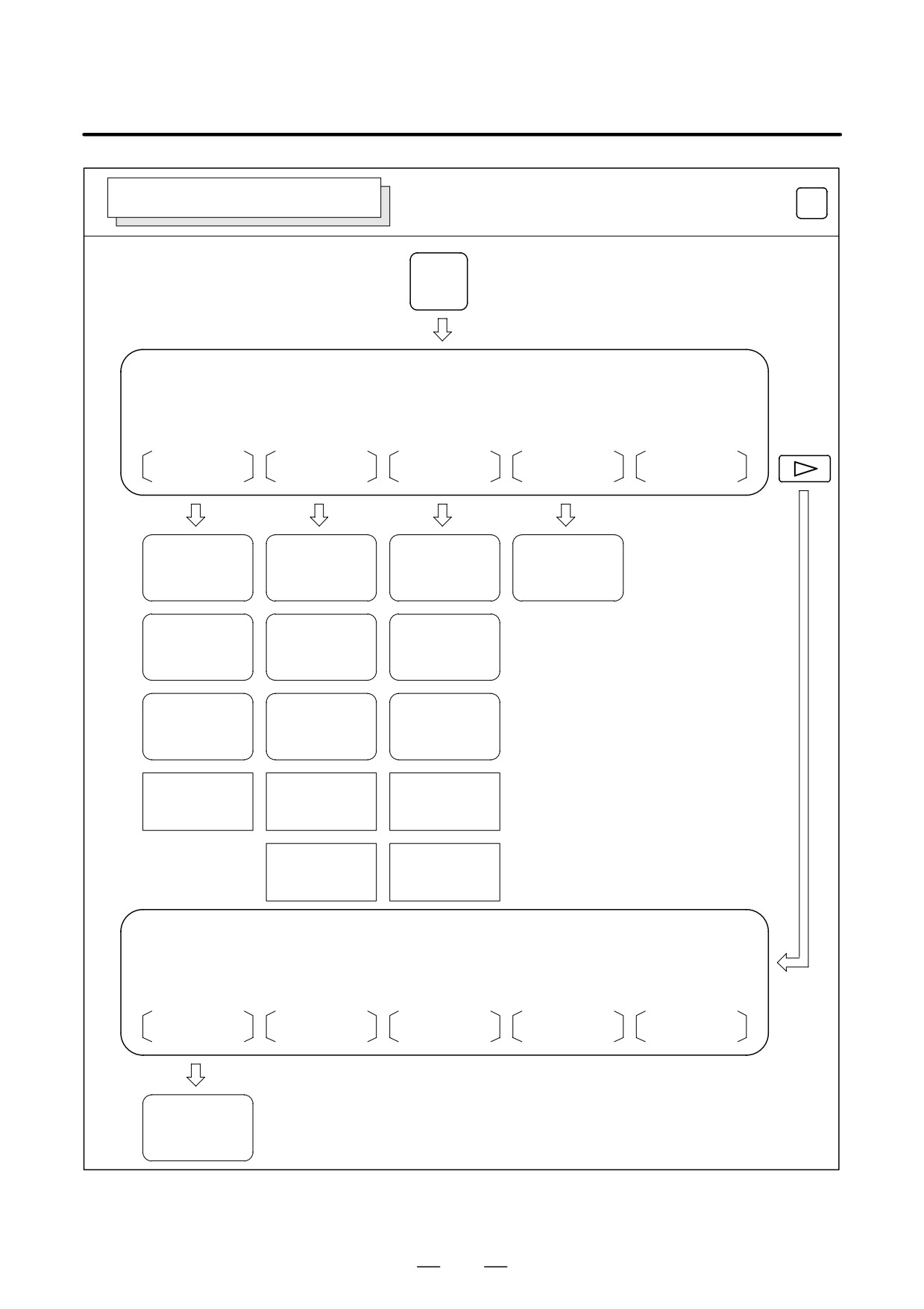
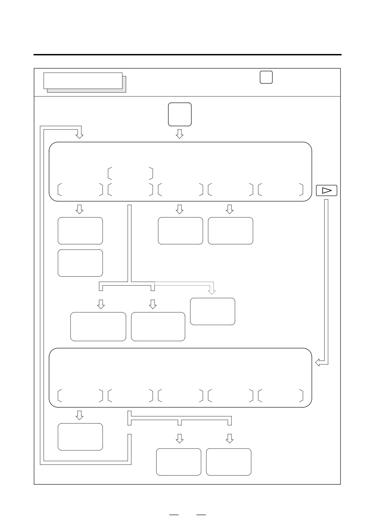
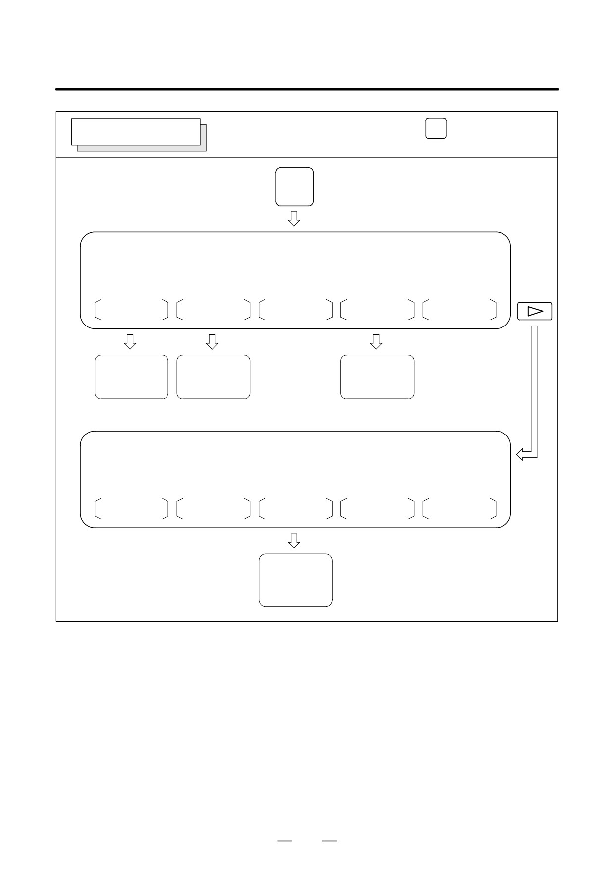
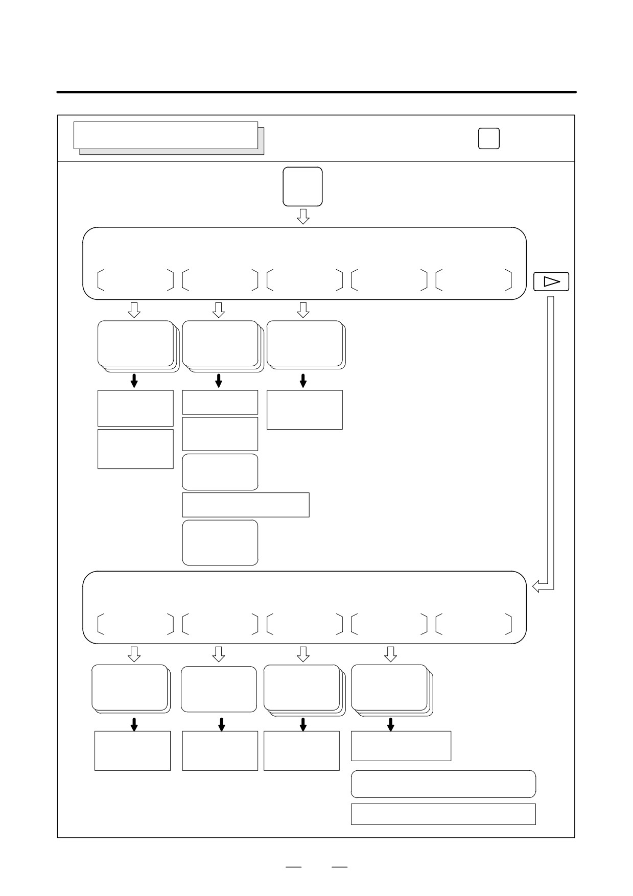
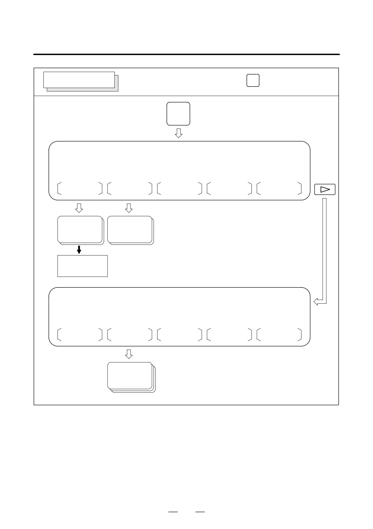
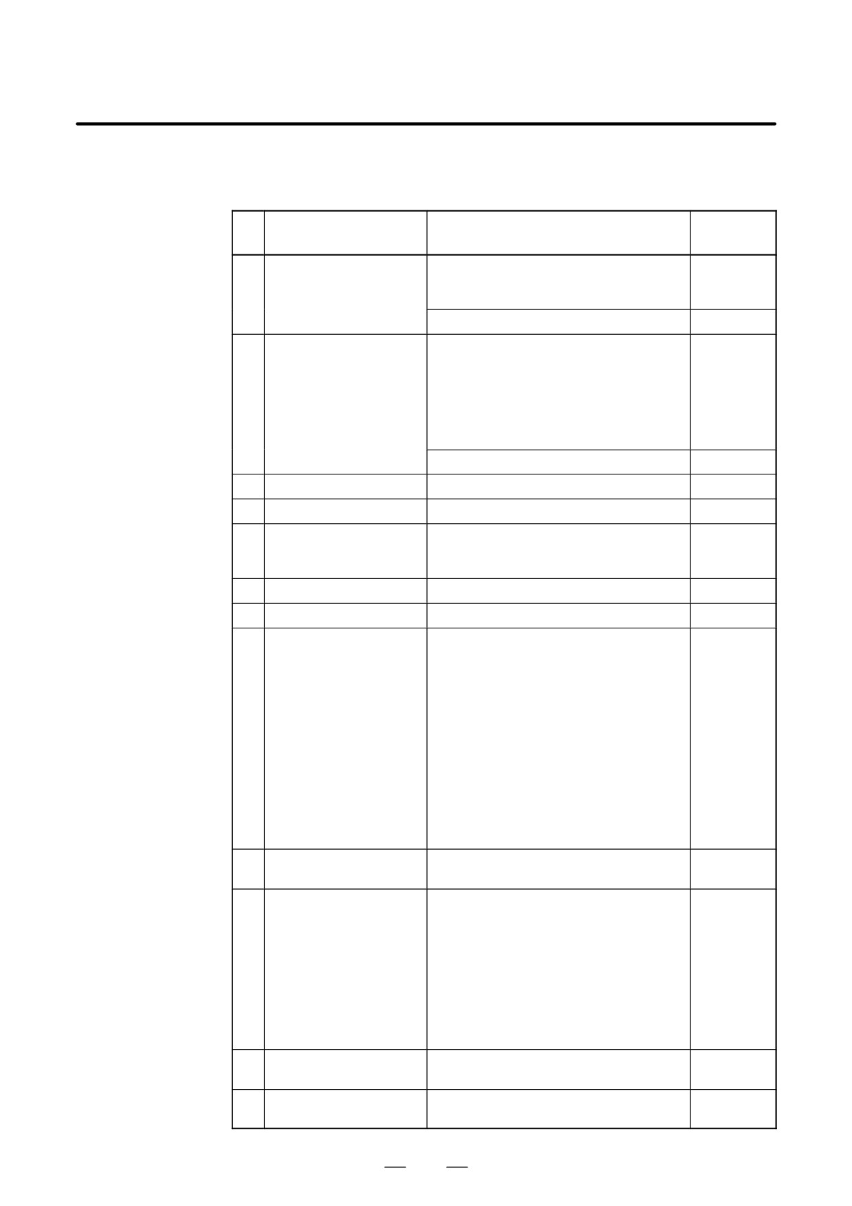
⋅Screen transition chart
The screen transition for when each function key on the MDI panel is
pressed is shown below. The subsections referenced for each screen are
OFFSET
also shown. See the appropriate subsection for details of each screen and
HELP
POS
PROG
SETTING
CUSTOM
the setting procedure on the screen. See other chapters for screens not
SYSTEM
MESSAGE
GRAPH
described in this chapter.
See Chapter 7 for the screen that appears when function key
MESSAGE
is
MDI function keys
pressed. See Chapter 12 for the screen that appears when function key
(Shaded keys (
) are described
in this chapter.)
GRAPH
is pressed. See Chapter 13 for the screen that appears when function
key
HELP
is pressed. In general, function key
CUSTOM
is prepared by the
machine tool builder and used for macros. Refer to the manual issued by
the machine tool builder for the screen that appears when function key
CUSTOM
is pressed.
D Data protection key
The machine may have a data protection key to protect part programs,
tool compensation values, setting data, and custom macro variables.
Refer to the manual issued by the machine tool builder for where the data
protection key is located and how to use it.
986
B-63534EN/02
OPERATION
11. SETTING AND DISPLAYING DATA
POSITION DISPLAY SCREEN
Screen transition triggered by the function key
POS
POS
Current position screen
ABS
REL
ALL
HNDL
(OPRT)
Position display of
Position displays
Total position display
Manual handle
workpiece coordiĆ
relative coordinate
of each coordinate
interruption
system
nate system
system
⇒See III-4.8.
⇒ See III-11.1.3.
⇒ See III-11.1.1.
⇒ See III-11.1.2.
Display of part
Display of part
Display of part
count and run
count and run
count and run
time
time
time
⇒ See III-11.1.6.
⇒ See III-11.1.6.
⇒ See III-11.1.6.
Display of actual
Display of actual
Display of actual
speed
speed
speed
⇒ See III-11.1.5.
⇒ See III-11.1.5.
⇒ See III-11.1.5.
Setting of floating
Setting of floating
Setting of floating
reference position
reference position
reference position
⇒ See III-11.1.7.
⇒ See III-11.1.7.
⇒ See III-11.1.7.
Setting of relative
Setting of relative
coordinate values
coordinate values
⇒ See III-11.1.2.
⇒ See III-11.1.2.
Current position screen
MONI
(OPRT)
Display of operĆ
ating monitor
⇒See III-11.1.8.
987
11. SETTING AND DISPLAYING DATA
OPERATION
B-63534EN/02
Screen transition triggered by the function key
PROG
PROGRAM SCREEN
in the MEMORY or MDI mode
PROG
*: Displayed in MDI mode
Program screen
MEM
MDI
PRGRM
CHECK
CURRNT
NEXT
(OPRT)
Display of proĆ
Display of current
Display of current
gram contents
block and modal
block and next
data
block
⇒ See III-11.2.1.
⇒ See III-11.2.2.
⇒ See III-11.2.3.
Display of program
number and seĆ
quence number
⇒ See III-11.6.1.
[ABS]
[REL]
Command
for MDI operation
Program being executed
Program being executed
⇒ See III-11.2.5.
Absolute coordinate value
Relative coordinate value
Distance to go
Distance to go
(Displayed in the
modal values
modal values
⇒ See III-11.2.4.
⇒ See III-11.2.4.
MDI mode)
Program screen
MEM
RSTR
FL.SDL
(OPRT)
Program restart
[PRGRM]
[DIR]
[SCHDUL]
screen
⇒ See III-4.5.
Display of file
Setting of
directory
schedule
⇒ See III-4.6.
See III-4.6.
988
B-63534EN/02
OPERATION
11. SETTING AND DISPLAYING DATA
Screen transition triggered by the function key
PROG
PROGRAM SCREEN
in the EDIT mode
PROG
Program screen
EDIT
PRGRM
LIB
C.A.P.
(OPRT)
Conversational
Program editing
Program memory
programming
screen
and program diĆ
screen
⇒ See III-9
rectory
⇒ See III-10.4
⇒ See III-11.3.1.
Program screen
EDIT
FLOPPY
(OPRT)
File directory
screen for
floppy disks
⇒ See III-8.8
989
11. SETTING AND DISPLAYING DATA
OPERATION
B-63534EN/02
OFFSET
OFFSET/SETTING SCREEN
Screen transition triggered by the function key
SETTING
OFFSET
SETTING
Tool offset value
OFFSET
SETTING
WORK
(OPRT)
Display of tool
Display of setĆ
Display of workĆ
piece coordinate
offset value
ting data
system
⇒ See III-11.4.1.
⇒ See III-11.4.3
⇒ See III-11.4.6
Setting of tool
Parameter setting
Setting of work
⇒ See III-11.4.3.
offset data
origin offset value
⇒ See III-11.4.1.
Setting sequence
⇒ See III-11.4.6.
number comparison
Tool length
and stop
⇒ See III-11.4.4.
measurement
⇒ See III-11.4.2.
Setting run time and
parts count
⇒ See III-11.4.5.
Setting the number of parts required
⇒ See III-11.4.5.
Displaying setĆ
ting time
⇒ See III-11.4.5.
Tool offset value
MACRO
MENU
OPR
TOOLLF
(OPRT)
Displaying pattern
Displaying softĆ
Displaying tool life
Display of
ware operator's
management data
menu
macro variables
panel
åSee subsec. 11.4.9.
åSee subsec.
åSee subsec. 11.4.8.
åSee subsec. 11.4.10.
11.4.11.
Setting macro
Displaying pattern
Software operaĆ
Presetting tool life counter
variables
data
tor's panel switch
Clearing executing data
åSee subsec. 11.4.11.
åSee subsec. 11.4.8.
åSee subsec. 11.4.9.
åSee subsec. 11.4.10.
Displaying extended tool life management data
åSee subsec. 11.4.12.
Editing extended tool life management data
åSee subsec. 11.4.12.
990
B-63534EN/02
OPERATION
11. SETTING AND DISPLAYING DATA
SYSTEM SCREEN
Screen transition triggered by the function key
SYSTEM
SYSTEM
Parameter screen
PARAM
DGNOS
PMC
SYSTEM
(OPRT)
Display of
Display of
diagnosis
parameter screen
screen
⇒ See III-11.5.1
⇒ See III-7.3
Setting of parameter
⇒ See III-11.5.1
Parameter screen
PITCH
SV.PRM
SP.PRM
(OPRT)
Display of pitch
error data
⇒ See III-11.5.2.
991
11. SETTING AND DISPLAYING DATA
OPERATION
B-63534EN/02
D Setting screens
The table below lists the data set on each screen.
Table. 11 Setting screens and data on them
Reference
No.
Setting screen
Contents of setting
item
1
Tool offset value
Tool offset value
III-11.4.1
Tool length offset value
Cutter compensation value
Tool length measurement
III-11.4.2
2
Setting data(handy)
Parameter write
III-11.4.3
TV check
Punch code
Input unit (mm/inch)
I/O channel
Automatic insert of Sequence No.
Conversion of tape format (F15)
Sequence number comparison and stop
III-11.4.4
3
Setting data (mirror image)
Mirror image
III-11.4.3
4
Setting data (timer)
Parts required
III-11.4.5
5
Macro variables
Custom macro common variables
III-11.4.8
(#100 to #149) or (#100 to #199)
(#500 to #531) or (#500 to #599)
6
Parameter
Parameter
III-11.5.1
7
Pitch error
Pitch error compensation data
III-11.5.2
8
software operator’s panel
Mode selection
III-11.4.10
Jog feed axis selection
Jog rapid traverse
Axis selection for Manual pulse generator
Multiplication for manual pulse generator
Jog feedrate
Feedrate override
Rapid traverse override
Optional block skip
Single block
Machine lock
Dry run
Protect key
Feed hold
9
Tool life data
Life count
III-11.4.11
(Tool life management)
10
Tool life data
Life count type (cycle or minute)
III-11.4.12
(Extended tool life man-
Life value
agement)
Life counter
Tool number
H code
D code
New tool group
New tool number
Skipping tool
Clearing tool
11
Work coordinate system
Work origin offset value
III-11.4.6
setting
12
Current position display
Floating reference position
III-11.1.7
screen
992
B-63534EN/02
OPERATION
11. SETTING AND DISPLAYING DATA
11.1
POS
Press function key
to display the current position of the tool.
SCREENS
The following three screens are used to display the current position of the
DISPLAYED BY
tool:
FUNCTION KEY
POS
⋅Position display screen for the work coordinate system.
⋅Position display screen for the relative coordinate system.
#POS#
⋅Overall position display screen.
The above screens can also display the feedrate, run time, and the number
of parts. In addition, a floating reference position can be set on these
screens.
Function key
POS
can also be used to display the load on the servo motor
and spindle motor and the rotation speed of the spindle motor (operating
monitor display).
Function key
POS
can also be used to display the screen for displaying
the distance moved by handle interruption. See III- 4.8 for details on this
screen.
993
11. SETTING AND DISPLAYING DATA
OPERATION
B-63534EN/02
11.1.1
Displays the current position of the tool in the workpiece coordinate
system. The current position changes as the tool moves. The least input
Position Display in the
increment is used as the unit for numeric values. The title at the top of
Work Coordinate
the screen indicates that absolute coordinates are used.
System
Display procedure for the current position screen in the workpiece coordinate system
1
Press function key
POS
2
Press soft key [ABS].
3
Press the [ABS] soft key one more time to display the coordinates
along axes other than the six standard axes.
D Display with one-path control
ACTUAL POSITION(ABSOLUTE) O1000 N00010
X
123.456
Y
363.233
Z
0.000
PART COUNT
5
RUN TIME
0H15M CYCLE TIME 0H 0M38S
ACT.F
3000 MM/M
S 0 T0000
MEM STRT MTN ***
09:06:35
[
ABS
]
[ REL ]
[ ALL ]
[ HNDL ]
[ OPRT ]
D Display with two-path control
(7 soft keys display unit)
ACTUAL POSITION(ABSOLUTE) O1000 N00010
X
100.000
1
Z
200.000
1
X1
300.000
PART COUNT
5
RUN TIME
0H15M CYCLE TIME 0H 0M38S
ACT.F
3000 MM/M
S 0 T0000
MEM STRT MTN ***
09:06:35
HEAD1
[
ABS
]
[ REL ]
[ ALL ]
[ HNDL ]
[(OPRT)]
994
B-63534EN/02
OPERATION
11. SETTING AND DISPLAYING DATA
D Display with two-path control
(12 soft keys display unit)
ACTUAL POSITION
O1000 N10010
O2000 N20010
(ACTUAL)
(ACTUAL)
X1
100.000
X2
400.000
Y1
200.000
Y2
500.000
Z1
300.000
Z2
600.000
(ACTUAL SPEED) F :
0MM/MIN
(ACTUAL SPEED) F :
0MM/MIN
S :
0RPM
S :
0RPM
(PARTS COUNT)
114
(PARTS COUNT)
114
(RUN TIME)
5H 3M
(RUN TIME)
5H 3M
(CYCLE TIME)
0H 0M 6S
(CYCLE TIME)
0H 0M 6S
MEM STOP *** ***
12:34:56 HEAD1
ABS
REL
ALL
+
Explanations
D Display including
Bits 6 and 7 of parameter 3104 (DAL, DAC) can be used to select whether
compensation values
the displayed values include tool length offset and cutter compensation.
D Displaying the sixth and
Only the coordinates for the first to fifth axes are displayed initially
subsequent axes
whenever when there are six or more controlled axes. Pressing the [ABS]
soft key displays the coordinates for the sixth and subsequent axes.
995
11. SETTING AND DISPLAYING DATA
OPERATION
B-63534EN/02
11.1.2
Displays the current position of the tool in a relative coordinate system
based on the coordinates set by the operator. The current position changes
Position Display in the
as the tool moves. The increment system is used as the unit for numeric
Relative Coordinate
values. The title at the top of the screen indicates that relative coordinates
System
are used.
Display procedure for the current position screen with the relative coordinate system
1
Press function key
POS
2
Press soft key [REL].
3
Press the [REL] soft key one more time to display the coordinates
along axes other than the six standard axes.
D Display with one-path control
ACTUAL POSITION(RELATIVE)
O1000 N00010
X
123.456
Y
363.233
Z
0.000
PART COUNT
5
RUN TIME
0H15M CYCLE TIME 0H 0M38S
ACT.F
3000 MM/M
S 0 T0000
MEM STRT MTN ***
09:06:35
[ ABS ]
[
REL ]
[ ALL ]
[ HNDL ]
[ OPRT ]
See Explanations for the procedure for setting the coordinates.
D Display with two-path control
(7 soft keys display unit)
ACTUAL POSITION(RELATIVE) O1000 N00010
X
1
100.000
Y
1
200.000
Z
1
300.000
PART COUNT
5
RUN TIME
0H15M CYCLE TIME 0H 0M38S
ACT.F
3000 MM/M
S 0 T0000
MEM STRT MTN ***
09:06:35
HEAD1
[ ABS ]
[
REL
]
[ ALL ]
[ HNDL ]
[(OPRT)]
996
B-63534EN/02
OPERATION
11. SETTING AND DISPLAYING DATA
D Display with two-path control)
(12 soft keys display unit)
ACTUAL POSITION
O1000 N10010
O2000 N20010
(RELATIVE)
(RELATIVE)
X1
100.000
X2
400.000
Y1
200.000
Y2
500.000
Z1
300.000
Z2
600.000
(ACTUAL SPEED) F :
0MM/MIN
(ACTUAL SPEED) F :
0MM/MIN
S :
0RPM
S :
0RPM
(PARTS COUNT)
114
(PARTS COUNT)
114
(RUN TIME)
5H 3M
(RUN TIME)
5H 3M
(CYCLE TIME)
0H 0M 6S
(CYCLE TIME)
0H 0M 6S
MEM STOP *** *** 12:34:56 HEAD1
ABS
REL
ALL
HNDL
(OPRT)
+
Explanations
D Setting the relative
The current position of the tool in the relative coordinate system can be
coordinates
reset to 0 or preset to a specified value as follows:
Procedure to set the axis coordinate to a specified value
Procedure
1
Enter an axis address (such as X or Y) on the screen for the relative
coordinates. The indication for the specified axis blinks and the soft
keys change as shown on the left.
X
246.912
2
⋅
To reset the coordinate to 0, press soft key [ORGIN]. The relative
Y
913.780
coordinate for the blinking axis is reset to 0.
Z
578.246
>X
⋅
To preset the coordinate to a specified value, enter the value and
MEM
press soft key [PRESET]. The relative coordinate for the blinking
PRESET
ORIGIN
axis is set to the entered value.
Procedure to reset all axes
Procedure
1
Press soft key [(OPRT)].
ABS
REL
ALL
(OPRT)
2
Press soft key [ORIGIN].
ORIGIN
3
Press soft key [ALLEXE].
ALLEXE
EXEC
The relative coordinates for all axes are reset to 0.
997
11. SETTING AND DISPLAYING DATA
OPERATION
B-63534EN/02
D Display including
Bits 6 and 7 of parameter 3104 (DRL, DRC) can be used to select whether
compensation values
the displayed values include tool length offset and cutter compensation.
D Presetting by setting a
Bit 3 of parameter 3104 (PPD) is used to specify whether the displayed
coordinate system
positions in the relative coordinate system are preset to the same values
as in the workpiece coordinate system when a coordinate system is set by
a G92 command or when the manual reference position return is made.
D Displaying the sixth and
Only the coordinates for the first to fifth axes are displayed initially
subsequent axes
whenever when there are six or more controlled axes. Pressing the [ABS]
soft key displays the coordinates for the sixth and subsequent axes.
998
B-63534EN/02
OPERATION
11. SETTING AND DISPLAYING DATA
11.1.3
Displays the following positions on a screen : Current positions of the
tool in the workpiece coordinate system, relative coordinate system, and
Overall Position
machine coordinate system, and the remaining distance. The relative
Display
coordinates can also be set on this screen. See III-11.1.2 for the
procedure.
Procedure for displaying overall position display screen
Procedure
1
Press function key
POS
2
Press soft key [ALL].
D Display with one-path control
ACTUAL POSITION
O1000 N00010
(RELATIVE)
(ABSOLUTE)
X 246.912
X 123.456
Y 913.780
Y 456.890
Z 1578.246
Z
789.123
(MACHINE)
(DISTANCE TO GO)
X
0.000
X
0.000
Y
0.000
Y
0.000
Z
0.000
Z
0.000
PART COUNT
5
RUN TIME
0H15M CYCLE TIME 0H 0M38S
ACT.F
3000 MM/M
S 0 T0000
MEM **** *** ***
09:06:35
[ ABS ]
[ REL ]
[
ALL ]
[ HNDL ]
[ OPRT ]
D Display with two-path control
(7 soft keys display unit)
ACTUAL POSITION
O1000 N00010
(RELATIVE)
(ABSOLUTE)
X1
100.000
X1
100.000
Y1
200.000
Y1
200.000
Z1
300.000
Z1
300.000
(MACHINE)
(DISTANCE TO GO)
X1
100.000
X1
000.000
Y1
200.000
Y1
000.000
Z1
300.000
Z1
000.000
Z2
000.000
PART COUNT
5
RUN TIME
0H15M CYCLE TIME 0H 0M38S
ACT.F
3000 MM/M
S 0 T0000
MEM **** *** ***
09:06:35
HEAD1
[ ABS ]
[ REL ]
[
ALL ]
[ HNDL ]
[(OPRT)]
999