FANUC Series 16i/160i/160is-MB, Series 18i/180i/180is-MB5, Series 18i/180i/180is-MB. Operator's Manual - page 35
11. SETTING AND DISPLAYING DATA
OPERATION
B-63534EN/02
D Display with two-path control
(12 soft keys display unit)
ACTUAL POSITION O1000 N10010
O2000 N20010
(RELATIVE)
(ABSOLUTE)
(RELATIVE)
(ABSOLUTE)
X1
100.000
X1
100.000
X1
100.000
X1
100.000
Y1
100.000
Y1
100.000
Y1
200.000
Y1
200.000
Z1
300.000
Z1
300.000
Z1
300.000
Z1
300.000
(MACHINE)
(DISTANCE TO GO)
(MACHINE)
(DISTANCE TO GO)
X1
100.000
X1
000.000
X1
100.000
X1
000.000
Y1
200.000
Y1
000.000
Y1
200.000
Y1
000.000
Z1
300.000
Z1
000.000
Z1
300.000
Z1
000.000
(ACTUAL SPEED) F :
0MM/MIN
(ACTUAL SPEED) F :
0MM/MIN
S :
0RPM
S :
0RPM
(PARTS COUNT)
114
(PARTS COUNT)
114
(RUN TIME)
5H 3M
(RUN TIME)
5H 3M
(CYCLE TIME) 0H 0M
6S
(CYCLE TIME) 0H 0M
6S
MEM STOP *** ***
12:34:56 HEAD1
ABS
REL
ALL
+
Explanations
D Coordinate display
The current positions of the tool in the following coordinate systems are
displayed at the same time:
D Current position in the relative coordinate system
(relative coordinate)
D Current position in the work coordinate system
(absolute coordinate)
D Current position in the machine coordinate system
(machine coordinate)
D Distance to go (distance to go)
D Distance to go
The distance remaining is displayed in the MEMORY or MDI mode. The
distance the tool is yet to be moved in the current block is displayed.
D Machine coordinate
The least command increment is used as the unit for values displayed in
system
the machine coordinate system. However, the least input increment can
be used by setting bit 0 (MCN) of parameter 3104.
D Displaing the sixth and
Only the coordinates for the first to fifth axes are displayed initially
subsequent axes
whenever there are six or more controlled axes. Pressing the [ALL] soft
key displays the coordinates for the sixth and subsequent axes.
D Displaying the fifth and
Relative coordinates cannot be displayed together with absolute
subsequent axes
coordinates whenever there are five or more controlled axes. Pressing the
[ALL] soft key toggles the display between absolute and relative
coordinates.
D Resetting the relative
The total position display screen also supports the resetting of the relative
coordinates
coordintes to 0 or presetting of them to specified values. See the procedure
for resetting the relative coordintes described in Subsection III-11.1.2
1000
B-63534EN/02
OPERATION
11. SETTING AND DISPLAYING DATA
11.1.4
A workpiece coordinate system shifted by an operation such as manual
intervention can be preset using MDI operations to a pre-shift workpiece
Presetting the
coordinate system. The latter coordinate system is displaced from the
Workpiece Coordinate
machine zero point by a workpiece zero point offset value.
System
A command (G92.1) can be programmed to preset a workpiece coordinate
system.
(See II-7.2.4 in the section for programming.)
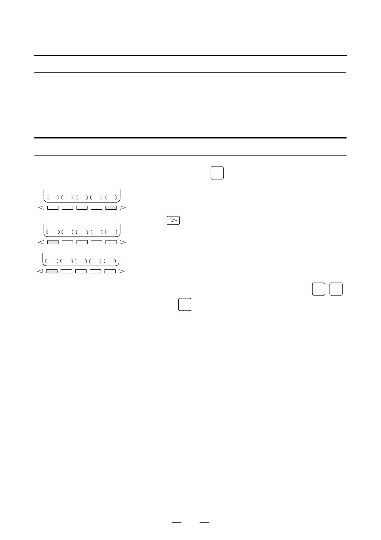
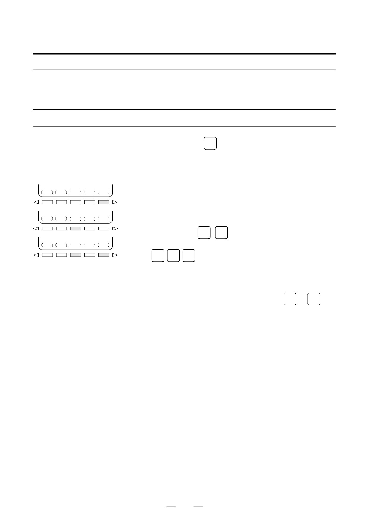
Procedure for Presetting the Workpiece Coordinate System
Procedure
1
Press function key
POS
2
Press soft key [(OPRT)].
ABS
REL
ALL
(OPR)
3
When [WRK-CD] is not displayed, press the continuous menu
key
WRK-CD
4
Press soft key [WRK-CD].
ALLAXS
AXS-CD
5
Press soft key [ALLAXS] to preset all axes.
6
To preset a particular axis in step 5, enter the axis name (
X
,
Y
,
...) and
0
, then press soft key [AXS-CD].
Explanations
D Operation mode
This function can be executed when the reset state or automatic operation
stop state is entered, regardless of the operation mode.
D Presetting relative
As with absolute coordinates, bit 3 (PPD) of parameter No. 3104 is used
coordinates
to specify whether to preset relative coordinates (RELATIVE).
1001
11. SETTING AND DISPLAYING DATA
OPERATION
B-63534EN/02
11.1.5
The actual feedrate on the machine (per minute) can be displayed on a
current position display screen or program check screen by setting bit 0
Actual Feedrate
(DPF) of parameter 3105. On the 12 soft keys display unit, the actual
Display
feedrate is always displayed.
Display procedure for the actual feedrate on the current position display screen
Procedure
1
Press function key
POS
to display a current position display screen.
ACTUAL POSITION(ABSOLUTE) O1000 N00010
X
123.456
Y
363.233
Z
0.000
PART COUNT
5
RUN TIME
0H15M CYCLE TIME 0H 0M38S
ACT.F
3000 MM/M
S 0 T0000
MEM STRT MTN ***
09:06:35
[
ABS
]
[ REL ]
[ ALL ]
[ HNDL ]
[ OPRT ]
Actual feedrate is displayed after ACT.F.
Explanations
The actual feedrate is displayed in units of millimeter/min or inch/min
(depending on the specified least input increment) under the display of the
current position.
D Actual feedrate value
The actual rate is calculated by the following expression:
n
Fact + ȍ
Ǹ
(fi)2
i+1
where
n
: Number of axes
fi
: Cutting feed rate in the tangential direction of each axis or rapid
traverse rate
Fact : Actual feedrate displayed
The display unit: mm/min (metric input).
inch/min (Inch input, Two digits below the decimal
point are displayed.)
The feedrate along the PMC axis can be omitted by setting bit 1 (PCF) of
parameter 3105.
D Actual feedrate display
In the case of feed per revolution and thread cutting, the actual feedrate
of feed per revolution
displayed is the feed per minute rather than feed per revolution.
1002
B-63534EN/02
OPERATION
11. SETTING AND DISPLAYING DATA
D Actual feedrate display
In the case of movement of rotary axis, the speed is displayed in units of
of rotary axis
deg/min but is displayed on the screen in units of input system at that time.
For example, when the rotary axis moves at 50 deg/min, the following is
displayed: 0.50 INCH/M
D Actual feedrate display
The program check screen also displays the actual feedrate.
on the other screen
1003
11. SETTING AND DISPLAYING DATA
OPERATION
B-63534EN/02
11.1.6
The run time, cycle time, and the number of machined parts are displayed
on the current position display screens.
Display of Run Time
and Parts Count
Procedure for displaying run time and parts count on the current position display screen
Procedure
1
Press function key
POS
to display a current position display screen.
ACTUAL POSITION(RELATIVE) O1000 N00010
X
123.456
Y
363.233
Z
0.000
PART COUNT
5
RUN TIME
0H15M CYCLE TIME 0H 0M38S
ACT.F
3000 MM/M
S 0 T0000
MEM STRT MTN ***
09:06:35
[ ABS ]
[
REL ]
[ ALL ]
[ HNDL ]
[ OPRT ]
The number of machined parts (PART COUNT), run time (RUN
TIME), and cycle time (CYCLE TIME) are displayed under the
current position.
Explanations
D PART COUNT
Indicates the number of machined parts. The number is incremented each
time M02, M30, or an M code specified by parameter 6710 is executed.
D RUN TIME
Indicates the total run time during automatic operation, excluding the stop
and feed hold time.
D CYCLE TIME
Indicates the run time of one automatic operation, excluding the stop and
feed hold time. This is automatically preset to 0 when a cycle start is
performed at reset state. It is preset to 0 even when power is removed.
D Display on the other
Details of the run time and the number of machined parts are displayed
screen
on the setting screen. See III-11.4.5.
D Parameter setting
The number of machined parts and run time cannot be set on current
position display screens. They can be set by parameters No. 6711, 6751,
and 6752 or on the setting screen.
D Incrementing the number
Bit 0 (PCM) of parameter 6700 is used to specify whether the number of
of machined parts
machined parts is incremented each time M02, M30, or an M code
specified by parameter 6710 is executed, or only each time an M code
specified by parameter 6710 is executed.
1004
B-63534EN/02
OPERATION
11. SETTING AND DISPLAYING DATA
11.1.7
To perform floating reference position return with a G30.1 command, the
floating reference position must be set beforehand.
Setting the Floating
Reference Position
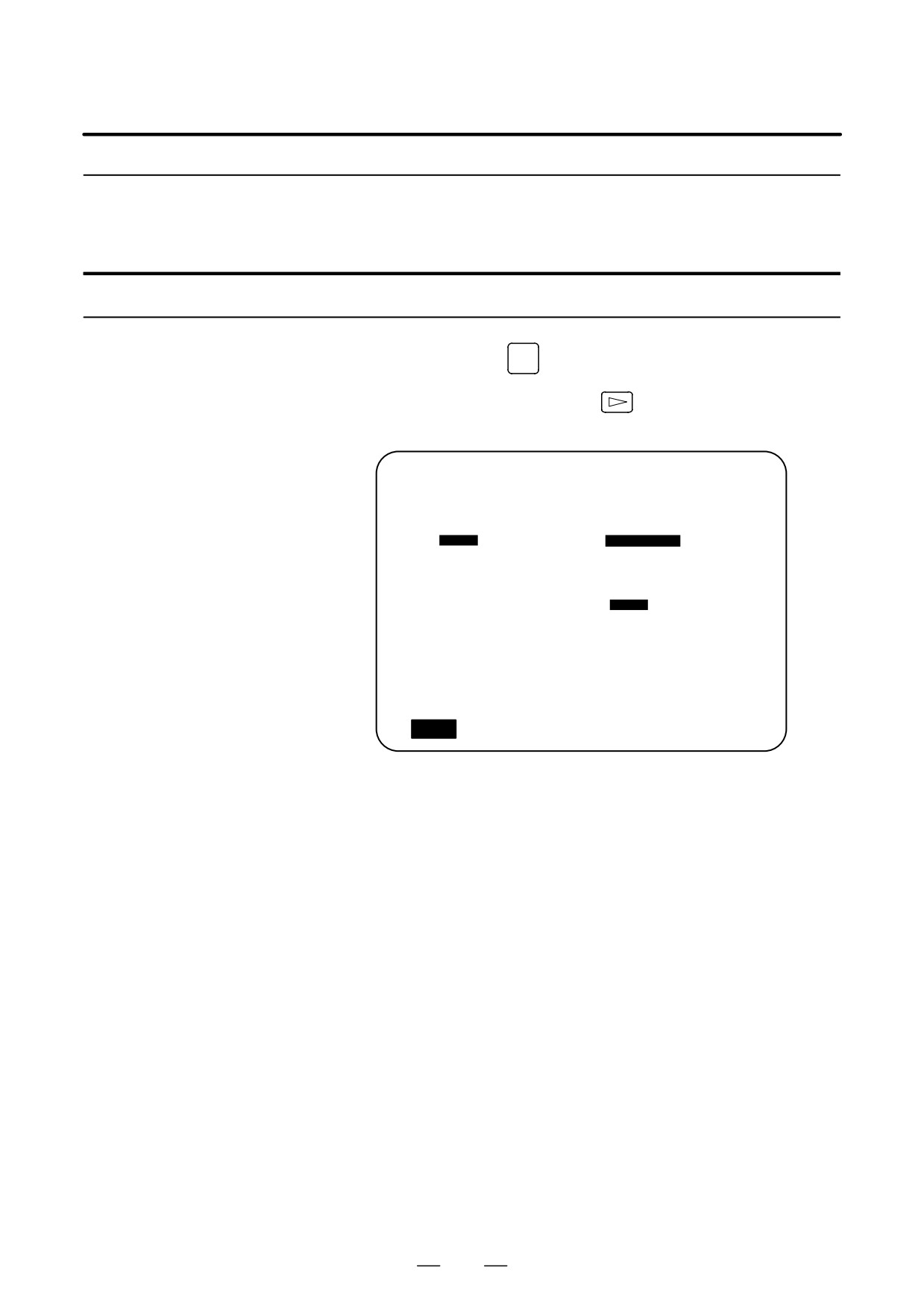
Procedure for setting the floating reference position
Procedure
1
Press function key
POS
to display a screen used for displaying the
current position.
2
Move the tool to the floating reference position by jogging.
3
Press soft key [(OPRT)].
ABS
REL
ALL
(OPRT)
4
Press soft key [SET FRP].
5
To register the floating reference positions for all axes, press soft key
[ALLEXE].
SET FRP
To register the floating reference position of a specific axis, enter the
name of the axis [
X
,
Y
, etc.), then press soft key [EXEC]. Two
ALLEXE
EXEC
or more names can be entered consecutively
(e.g.,
X
Y
Z
[EXEC]).
The above operation stores the floating reference position. It can be
checked with parameter (no. 1244).
6
In step 4, the floating reference position along a specified axis can
also be stored by entering the axis name (such as
X
or
Y
) and
pressing soft key [SET FRP].
Explanations
D Presetting the relative
By parameter FPC (bit 3 of parameter 1201), the relative position can be
coordinate system
preset to 0 when a floating reference position is registered.
1005
11. SETTING AND DISPLAYING DATA
OPERATION
B-63534EN/02
11.1.8
The reading on the load meter can be displayed for each servo axis and
the serial spindle by setting bit 5 (OPM) of parameter 3111 to 1. The
Operating Monitor
reading on the speedometer can also be displayed for the serial spindle.
Display
Procedure for displaying the operating monitor
Procedure
1
Press function key
POS
to display a current position display screen.
2
Press the continuous-menu key
3
Press soft key [MONI].
OPERATING MONITOR
O0001 N00001
(LOAD METER)
X :
80% S1 :
01%
Y : * * * * *
0%
(SPEED METER RPM)
Z : * * * * *
0%
S1 :
1500
PART COUNT
5
RUN TIME
0H15M CYCLE TIME 0H 0M38S
ACT.F
3000 MM/M
MEM STRT MTN ***
09:06:35
[
MONI
]
[
]
[
]
[
]
[ (OPRT) ]
[
Explanations
D Display of the servo axes
The reading on the load meter can be displayed for up to eight servo axes
by setting parameters 3151 to 3158.
When all these parameters are set to 0, data is displayed only to the 3rd
axis.
D Display of the spindle
When serial spindles are used, the reading on the load meter and
axes
speedometer can be displayed only for the main serial spindle.
D Unit of graph
The bar graph for the load meter shows load up to 200% (only a value is
displayed for load exceeding 200%). The bar graph for the speedometer
shows the ratio of the current spindle speed to the maximum spindle speed
(100%).
D Load meter
The reading on the load meter depends on servo parameter 2086 and
spindle parameter 4127.
1006
B-63534EN/02
OPERATION
11. SETTING AND DISPLAYING DATA
D Speedometer
Although the speedometer normally indicates the speed of the spindle
motor, it can also be used to indicate the speed of the spindle by setting
bit 6 (OPS) of parameter 3111 to 1.
The spindle speed to be displayed during operation monitoring is
calculated from the speed of the spindle motor (see the formula below).
The spindle speed can therefore be displayed, during operation
monitoring, even when no position coder is used. To display the correct
spindle speed, however, the maximum spindle speed for each gear
(spindle speed at each gear ratio when the spindle motor rotates at the
maximum speed) must be set in parameters No. 3741 to 3744.
The input of the clutch and gear signals for the first serial spindle is used
to determine the gear which is currently selected. Control the input of the
CTH1A and CTH2A signals according to the gear selection, by referring
to the table below.
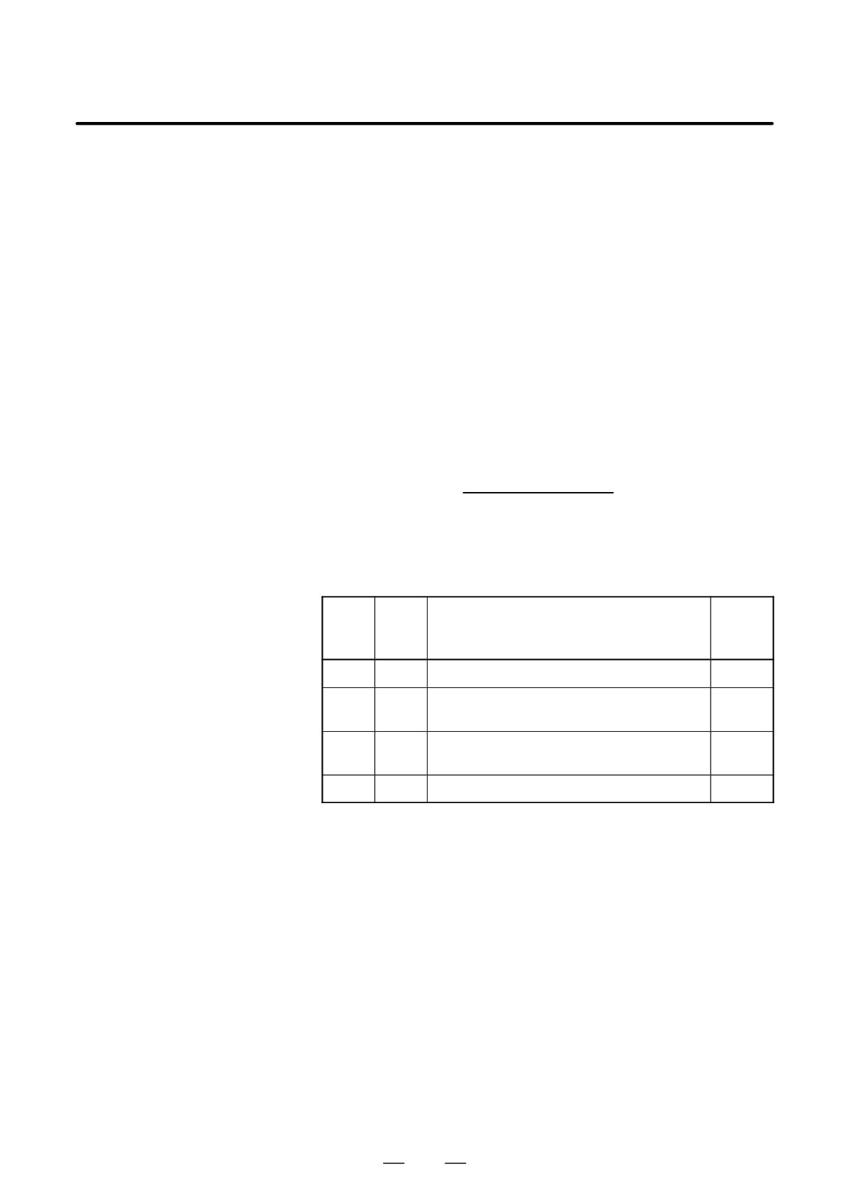
(Formula for calculating the spindle speed to be displayed)
Spindle speed
Maximum spindle
Speed of spindle motor
displayed during
=
× speed with the
Maximum speed of
operation monitoring
gear being used
spindle motor
The following table lists the correspondence between clutch and gear
selection signals CTH1A and CTH2A, used to determine the gear being
used, and parameters:
Serial
CTH1A
CTH2A
Parameter
spindle
spec
0
0
=No.3741 (Maximum spindle speed with gear 1)
HIGH
0
1
=No.3742 (Maximum spindle speed with gear 2)
MEDIUM
HIGH
1
0
=No.3743 (Maximum spindle speed with gear 3)
MEDIUM
LOW
1
1
=No.3744 (Maximum spindle speed with gear 4)
LOW
The speed of the spindle motor and spindle can be displayed, during
operation monitoring, only for the first serial spindle and the spindle
switching axis for the first serial spindle. It cannot be displayed for the
second spindle.
D Color of graph
If the value of a load meter exceeds 100%, the bar graph turns purple.
1007
11. SETTING AND DISPLAYING DATA
OPERATION
B-63534EN/02
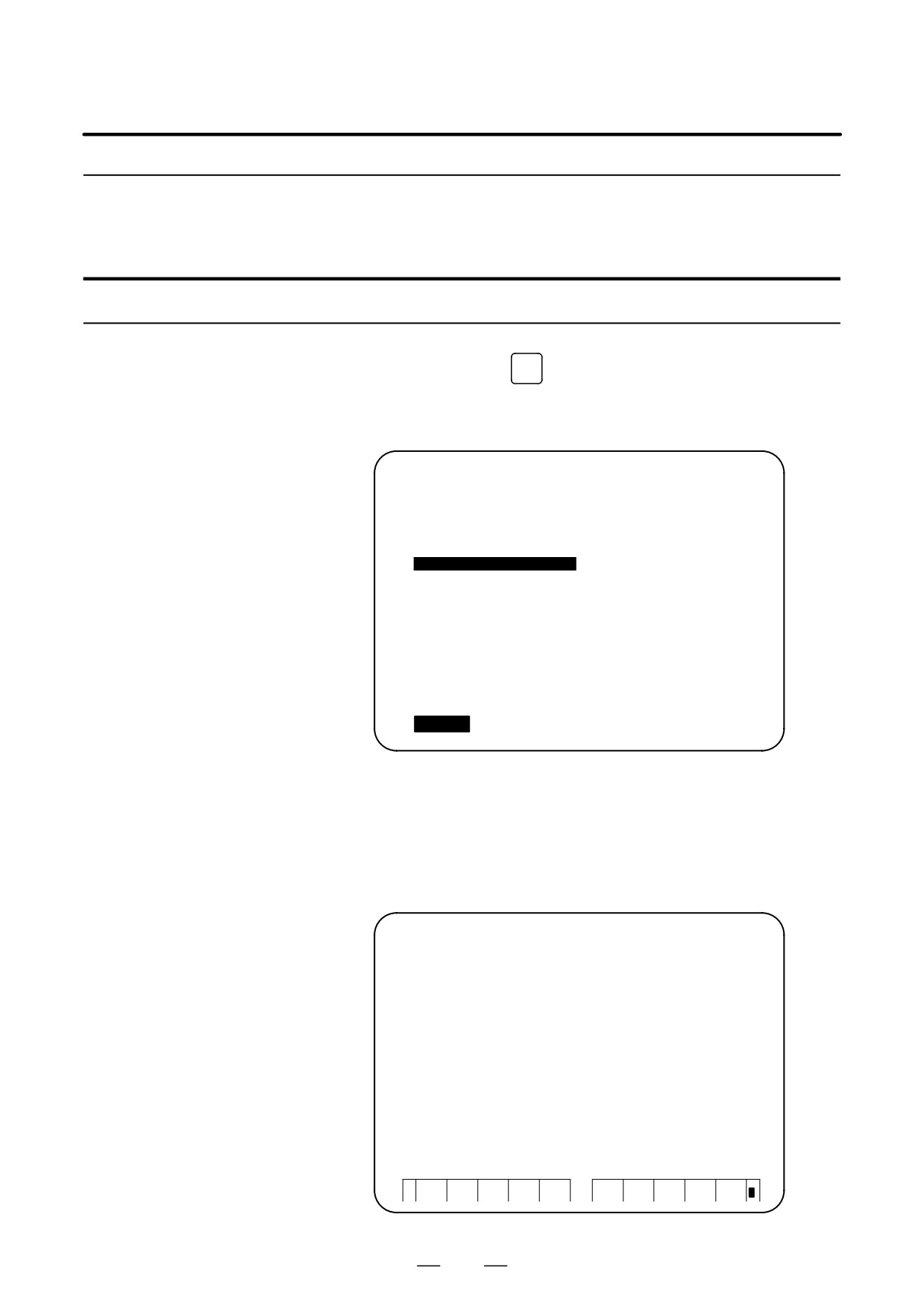
This section describes the screens displayed by pressing function key
11.2
PROG
in MEMORY or MDI mode.The first four of the following screens
SCREENS
DISPLAYED BY
display the execution state for the program currently being executed in
MEMORY or MDI mode and the last screen displays the command values
FUNCTION KEY
#PROGOG#
for MDI operation in the MDI mode:
(IN MEMORY MODE
1. Program contents display screen
OR MDI MODE)
2. Current block display screen
3. Next block display screen
4. Program check screen
5. Program screen for MDI operation
6. Stamping the machining time
Function key
PROG
can also be pressed in MEMORY mode to display the
program restart screen and scheduling screen.
See III-4.5 for the program restart screen.
See III-4.6 for the scheduling screen.
1008
B-63534EN/02
OPERATION
11. SETTING AND DISPLAYING DATA
11.2.1
Displays the program currently being executed in MEMORY or MDI
mode.
Program Contents
Display
Procedure for displaying the program contents
1
Press function key
PROG
to display the program screen.
2
Press chapter selection soft key [PRGRM].
The cursor is positioned at the block currently being executed.
PROGRAM
O2000 N00130
O2000 ;
N100 G92 X0 Y0 Z70. ;
N110 G91 G00 Y-70. ;
N120 Z-70. ;
N130 G42 G39 I-17.5 ;
N140 G41 G03 X-17.5 Y17.5 R17.5 ;
N150 G01 X-25. ;
N160 G02 X27.5 Y27.5 R27.5 ;
N170 G01 X20. ;
N180 G02 X45. Y45. R45. ;
> _
S 0 T0000
MEM STRT
***
16:05:59
[ PRGRM
]
[ CHECK ] [ CURRNT ] [ NEXT ] [ (OPRT) ]
Explanations
D 12 soft keys display unit
On the 12 soft keys display unit, the contents of the program are displayed
on the right half of the screen or on the entire screen (switched each time
soft key [PRGRM] is pressed).
PROGRAM
O0006 N00000
O0003 ;
N015
G99G82X550.0Y-450.0
N001
G92X0Y0Z0;
Z-130.0R-97.0P300F70;
N002
G90 G00 Z250.0 T11 M6;
N016
G98Y-650.0;
N003
G43 Z0 H11;
N017
G99X1050.0;
N004 S30 M3
N018
G98Y-450.0;
N005
G99 G81X400.0 R Y-350.0
N019
G00X0Y0M5;
Z-153.0R-97.0 F120;
N020
G49Z250.0T31M6;
N006
Y-550.0;
N021
G43Z0H31;
N007
G98Y-750.0;
N022
S10M3;
N008
G99X1200.0;
N023
G85G99X800.0Y-350.0
N009
Y-550.0;
Z-153.0R47.0F50;
N010
G98Y-350.0;
N024
G91Y-200.0K2;
N011
G00X0Y0M5;
N025
G28X0Y0M5;
N012
G49Z250.0T15M6;
N026
G49Z0;
N013
G43Z0H15;
N027
M0;
N014
S20M3;
EDIT **** *** ***
07:12:55
O SRH
SRH↑
SRH↓
REWIND
+
1009
11. SETTING AND DISPLAYING DATA
OPERATION
B-63534EN/02
11.2.2
Displays the block currently being executed and modal data in the
MEMORY or MDI mode.
Current Block Display
Screen
Procedure for displaying the current block display screen
Procedure
1
Press function key
PROG
2
Press chapter selection soft key [CURRNT].
The block currently being executed and modal data are displayed.
The screen displays up to 22 modal G codes and up to 11 G codes
specified in the current block.
PROGRAM
O2000 N00130
(CURRNT)
(MODAL)
G01
X 17.500
G67
G01 F 2000
G17
F 2000
G54
G17
G41
H
2
G64
G91
G80
G69
G22
G15
G94
G40 .1
G21 H 2 D
G25
G41
G49 T
G80
G98 S
G50
> _
S 0 T0000
MEM STRT
***
16:05:59
[ PRGRM ] [ CHECK ] [ CURRNT ] [ NEXT ] [ (OPRT) ]
Explanations
The current block display screen is not provided for 12 soft keys display
D 12 soft keys display unit
unit. Press soft key [PRGRM] to display the contents of the program on
the right half of the screen. The block currently being executed is
indicated by the cursor. Modal data is displayed on the left half of the
screen. The screen displays up to 18 modal G codes.
ACTUAL POSITION
O3001 N00000
(ABSOLUTE)
F
0
MM/MIN
X
0.000
Y
0.000
PROGRAM
Z
30.000
O3001 ;
G40 ;
G49 M06 T9 ;
G0 G54 G90 X0 Y0 ;
(MODAL)
G43 Z30. H5 S6000 M3 ;
M0 ;
G00 G40 G54
F
500 M
3
X17.5 Y-22 ;
G17 G43 G64
Z-6.5 ;
G90 G80 G69
H 5
G10 P11 R0.995 F500 ;
G22 G90 G15
D
T
9
M30 ;
G94 G50 G25
%
G21 G67
S
6000
SACT
0
>_
MEM **** *** ***
07:07:40
ABS
REL
ALL
PRGRM
NEXT
(OPRT)
+
1010
B-63534EN/02
OPERATION
11. SETTING AND DISPLAYING DATA
11.2.3
Displays the block currently being executed and the block to be executed
next in the MEMORY or MDI mode.
Next Block Display
Screen
Procedure for displaying the next block display screen
Procedure
1
Press function key
PROG
2
Press chapter selection soft key [NEXT].
The block currently being executed and the block to be executed next
are displayed.
The screen displays up to 11 G codes specified in the current block
and up to 11 G codes specified in the next block.
PROGRAM
O2000 N00130
(CURRNT)
(NEXT)
G01
X
17.500
G39
I
-17.500
G17
F
2000
G42
G41
H
2
G80
> _
S 0 T0000
MEM STRT
***
16:05:59
[ PRGRM ][ CHECK ][ CURRNT ][ NEXT
][ (OPRT) ]
1011
11. SETTING AND DISPLAYING DATA
OPERATION
B-63534EN/02
11.2.4
Displays the program currently being executed, current position of the
tool, and modal data in the MEMORY mode.
Program Check Screen
Procedure for displaying the program check screen
Procedure
1
Press function key
PROG
2
Press chapter selection soft key [CHECK].
The program currently being executed, current position of the tool,
and modal data are displayed.
D Display with one-path control
PROGRAM
O2000 N00130
(7 soft keys display unit)
O0010 ;
G92 G90 X100. Y200. Z50. ;
G00 X0 Y0 Z0 ;
G01 Z250. F1000 ;
(ABSOLUTE)(DIST TO GO) G00 G94
G80
X
0.000 X
0.000 G17 G21 G98
Y
0.000 Y
0.000 G90 G40 G50
Z
0.000 Z
0.000 G22 G49 G67
B
H M
T
D
F
S
> _
S 0 T0000
MEM STRT
***
16:05:59
[ PRGRM ][
CHECK
][ CURRNT ][ NEXT ][ (OPRT) ]
D Display with two-path control
(7 soft keys display unit)
PROGRAM
O2000 N00130
O0010;
G92
G90
X100. Y200.0 Z50. ;
G00
X0 Y0 Z0 ;
G01
Z250. F1000 ;
(ABSOLUTE) (DIST TO GO) G00
G94
G80
X1
0.000
X1
0.000
G17
G21
G98
Y1
0.000
Y1
0.000
G90
G40
G50
Z1
0.000
Z1
0.000
G22
G49
G67
B
H M
T
D
F
S
MEM STRT
***
16:05:59
HEAD1
[ PRGRM ]
[
CH ECK
]
[ CURRNT ]
[ NEXT ]
[ (OPRT) ]
1012
B-63534EN/02
OPERATION
11. SETTING AND DISPLAYING DATA
D Display with two-path control
(12 soft keys display unit)
PROGRAM CHECK O1000 N01010
PROGRAM CHECK
O2000 N02010
O0010 ;
O0020 ;
G92 G90 X100.0 Y200. Z50. ;
G28 X10. Y10. Z10. ;
G00 X0 Y0 Z0 ;
G00 X50. Y20. Z-50. ;
G01 Z250. F1000 ;
X100. ;
X50. Y20. ;
G01 Z-100. F2000 ;
(RELATIVE) (ABSOLUTE)
(DIST TO GO)
(RELATIVE) (ABSOLUTE)
(DIST TO GO)
X1
0.000 X1
0.000
X1
0.000
X2
0.000
X2
0.000
X2
0.000
Y1
0.000 Y1
0.000
Y1
0.000
Y2
0.000
Y2
0.000
Y2
0.000
Z1
0.000 Z1
0.000
Z1
0.000
Z2
0.000
Z2
0.000
Z2
0.000
(MODAL)
(MODAL)
G00
G22
G40
G98
M
G00
G98 G25
G67
M
G17
G94
G49
G50
M
G97
G21 G22
G54
M
G90
G21
G80
G67
M
G69
G40 G90
G18
M
H T
H T
B
B
F
1000.000
(ACT.F)
0MM/MIN
F
0.000
(ACT.F)
0MM/MIN
S
20
(ACT.S)
0RPM
S
30
(ACT.S)
0RPM
>_
S
0 T0000
MEM STOP *** *** 14:00:00 HEAD1
PRGRM CHECK
NEXT
(OPRT)
+
Explanations
D Program display
The screen displays up to four blocks of the current program, starting from
the block currently being executed. The block currently being executed
is displayed in reverse video. During DNC operation, however, only three
blocks can be displayed.
D Current position display
The position in the workpiece coordinate system or relative coordinate
system and the remaining distance are displayed. The absolute positions
and relative positions are switched by soft keys [ABS] and [REL].
When there are six or more controlled axes, pressing the [ABS] soft key
toggles the display between the absolute coordinates for the first to fifth
axes and those for the sixth to eighth axes. Pressing the [REL] soft key
toggles the relative coordinate display in the same way.
D Modal G codes
Up to 12 modal G codes are displayed.
D Display during automatic
During automatic operation, the actual speed, SACT, and repeat count are
operation
displayed. The key input prompt (>_) is displayed otherwise.
D T codes
Then bit 2 (PCT) of parameter No. 3108 is set to 1, the T codes specified
with the PMC (HD.T/NX.T) are displayed instead of those specified in
the program. Refer to the FANUC PMC Programming Manual
(B-61863E) for details of HD.T/NX.T.
1013
11. SETTING AND DISPLAYING DATA
OPERATION
B-63534EN/02
D 12 soft keys display unit
The program check screen is not provided for 12 soft keys display unit.
Press soft key [PRGRM] to display the contents of the program on the
right half of the screen. The block currently being executed is indicated
by the cursor. The current position of the tool and modal data are
displayed on the left half of the screen.
Up to 18 modal G codes are displayed.
ACTUAL POSITION
O3001 N00000
(ABSOLUTE)
F
0
MM/MIN
X 0.000
Y 0.000
PROGRAM
Z
30.000
O3001 ;
G40 ;
G49 M06 T9 ;
G0 G54 G90 X0 Y0 ;
(MODAL)
G43 Z30. H5 S6000 M3 ;
M0 ;
G00 G40 G54
F
500 M
3
X17.5 Y-22 ;
Z-6.5 ;
G17 G43 G64
G10 P11 R0.995 F500 ;
G90 G80 G69
H 5
M30 ;
G22 G90 G15
D
T
9
%
G94 G50 G25
>_
G21 G67
S
6000
MEM **** *** ***
07:07:40
SACT
0
ABS
REL
ALL
PRGRM
NEXT
(OPRT)
+
1014
B-63534EN/02
OPERATION
11. SETTING AND DISPLAYING DATA
11.2.5
Displays the program input from the MDI and modal data in the MDI
mode.
Program Screen for
MDI Operation
Procedure for displaying the program screen for MDI operation
Procedure
1
Press function key
PROG
2
Press chapter selection soft key [MDI].
The program input from the MDI and modal data are displayed.
PROGRAM (MDI)
O2000 N00130
O0000 G00 X100.0 Z200.0 ;
M03 ;
Program
G01 Z120.0 F500 ;
M98 P9010 ;
G00 Z0.0 ;
%
G00 G90 G94 G40 G80 G50 G54 G69
Modal information
G17 G22 G21 G49 G98 G67 G64 G15
H M
T
D
F
S
> _
S 0 T0000
MDI **** *** ***
16:05:59
[ PRGRM ] [
MDI ] [ CURRNT ] [ NEXT ] [ (OPRT) ]
Explanations
D MDI operation
See III-4.2 for MDI operation.
D Modal information
The modal data is displayed when bit 7 (MDL) of parameter 3107 is set
to 1. Up to 16 modal G codes are displayed. On the 12 soft keys display
unit, however, the contents of the program are displayed on the right half
of the screen and the modal data is displayed on the left half of the screen,
regardless of this parameter.
D Displaying during
During automatic operation, the actual speed, SACT, and repeat count are
automatic operation
displayed. The key input prompt (>_) is displayed otherwise.
1015
11. SETTING AND DISPLAYING DATA
OPERATION
B-63534EN/02
11.2.6
When a machining program is executed, the machining time of the main
program is displayed on the program machining time display screen. The
Stamping the
machining times of up to ten main programs are displayed in
Machining Time
hours/minutes/seconds. When more than ten programs are executed, data
for the oldest programs is discarded.
Procedure for Stamping Machining Time
Procedure 1
1
Select the memory operation mode, then press the
RESET
key.
Machining time
calculation and display
2
Select the program screen, then select a program whose machining
time is to be calculated.
3
Execute the program to perform actual machining.
4
When the
RESET
key is pressed, or M02 or M30 is executed, the
machining time count operation stops. When the machining time
display screen is selected, the program number of the stopped main
program and its machining time are displayed.
To display the machining time display screen, use the procedure
below.
(Machining time data can be displayed in any mode and
during background editing.)
S Press the function key
PROG
S Press the rightmost soft key once or twice to display soft key [TIME].
S Press soft key [TIME]. The machining time display screen appears.
Machining time display screen
PROGRAM (TIME)
O0010 N00002
NO.
TIME
O0020
12H48M02S
> _
EDIT **** *** ***
16:52:13
[
TIME
]
[
]
[
]
[
]
[ (OPRT) ]
1016
B-63534EN/02
OPERATION
11. SETTING AND DISPLAYING DATA
5
To calculate the machining times of additional programs, repeat the
above procedure. The machining time display screen displays the
executed main program numbers and their machining times
sequentially.
Note, that machining time data cannot be displayed for more than ten
main programs. When more than ten programs are executed, data for
the oldest programs is discarded. The screens below show how the
screen display changes from the initial state where the machining times
of ten main programs (O0020, O0040, ..., and O0200) are displayed
to the state where the machining time of the main program O0220 is
calculated.
PROGRAM (TIME)
O0000 N00000
NO.
TIME
O0020
12H48M01S
O0040
0H48M01S
O0060
4H16M01S
O0080
0H16M01S
O0100
1H20M01S
O0120
2H08M02S
O0140
2H32M01S
O0160
0H51M01S
O0180
15H04M01S
O0200
0H56M01S
>_
EDIT **** *** ***
16:52:13
[ TIME
][
][
][
][(OPRT) ]
PROGRAM (TIME)
O0000 N00000
NO.
TIME
O0040
0H48M01S
O0060
4H16M01S
O0080
0H16M01S
O0100
1H20M01S
O0120
2H08M02S
O0140
2H32M01S
O0160
0H51M01S
O0180
15H04M01S
O0200
0H56M01S
O0220
0H03M01S
>_
EDIT **** *** ***
16:52:20
[
TIME
][
][
][
][(OPRT) ]
1017
11. SETTING AND DISPLAYING DATA
OPERATION
B-63534EN/02
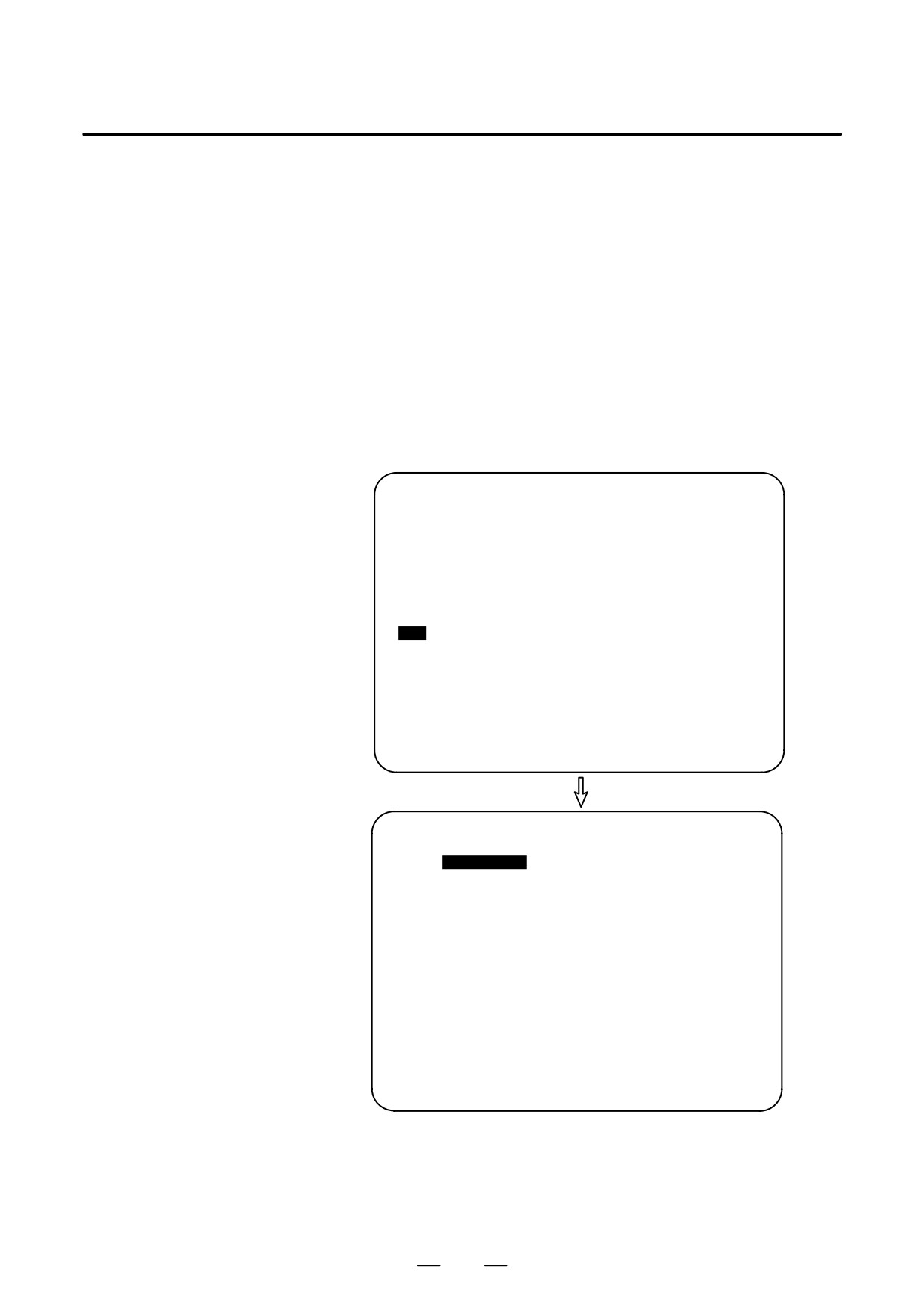
Procedure 2
1
To insert the calculated machining time of a program in a program as a
Stamping machining
comment, the machining time of the program must be displayed on
time
the machining time display screen. Before stamping the machining
time of the program, check that the machining time display screen
shows the program number
2
Set the part program storage and edit mode or background edit state
and select the program screen. Then select the program whose
machining time is to be inserted.
3
Suppose that the machining time of O0100 is displayed on the
machining time display screen.Press soft key [(OPRT)] to display the
operation soft keys. Then, hold down the rightmost soft key until soft
key [TIME-INSERT] appears. When soft key [TIME-INSERT] is
pressed, the cursor moves to the start of the program, and the
machining time of the program is inserted after the program number.
PROGRAM
O0100 N00000
O0100 ;
N10 G92 X100. Z10. ;
N20 S1500 M03 ;
N30 G00 X20.5 Z5. T0101 ;
N40 G01 X-10. F25. ;
N50 G02 X-16.5 Z-12. R2. ;
N60 G01 X40. ;
N70 X42. Z-13. ;
N80 Z-50. ;
N90 X44. Z-51. ;
N100 X80. ;
EDIT
*** *** *** ***
16:05:59
[ INS-TM ] [
] [
] [
] [
]
PROGRAM
O0100 N00000
O0100 (001H20M01S) ;
N10 G92 X100. Z10. ;
N20 S1500 M03 ;
N30 G00 X20.5 Z5. T0101 ;
N40 G01 Z-10. F25. ;
N50 G02 X16.5 Z-12. R2. ;
N60 G01 X40. ;
N70 X42. Z-13. ;
N80 Z-50. ;
N90 X44. Z-51. ;
N100 X80. ;
EDIT
*** *** *** ***
16:05:59
[ INS-TM ] [
] [
] [
] [
]
1018
B-63534EN/02
OPERATION
11. SETTING AND DISPLAYING DATA
4
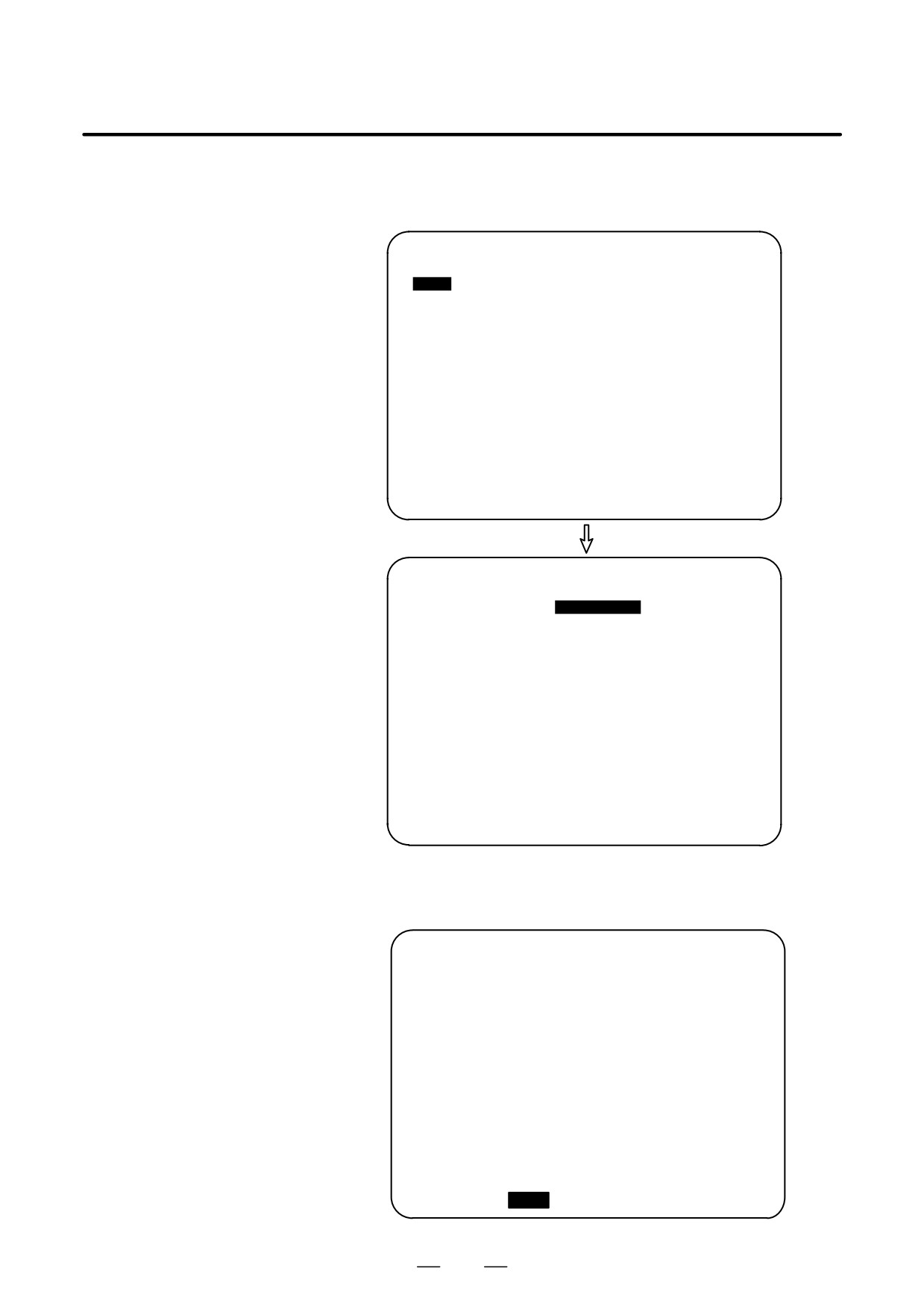
If a comment already exists in the block containing the program
number of a program whose machining time is to be inserted, the
machining time is inserted after the existing comment.
PROGRAM
O0100 0N0000
O0100
(SHAFT XSF001) ;
N10
G92
X100. Z10. ;
N20
S1500 M03 ;
N30 G00 X20.5 Z5. T0101 ;
N40 G01 X-10. F25. ;
N50 G02 X16.5 Z-12. R2. ;
N60 G01 X40. ;
N70 X42. Z-13. ;
N80 Z-50. ;
N90 X44. Z-51. ;
N100 X80. ;
EDIT
***
***
*** ***
16:52:13
[ INS-TM ]
[
]
[
]
[
]
[
]
PROGRAM
O0100 N00000
O0100 (SHAFT XSF001)(001H20M01S) ;
N10 G92 X100. Z10. ;
N20 S1500 M03 ;
N30 G00 X20.5 Z5. T0101 ;
N40 G01 Z-10. F25. ;
N50 G02 X16.5 Z-12. R2. ;
N60 G01 X40. ;
N70 X42. Z-13. ;
N80 Z-50. ;
N90 X44. Z-51. ;
N100 X80. ;
EDIT
***
***
***
***
16:52:13
[ INS-TM ] [
]
[
]
[
]
[
]
5
The machining time of a program inserted as a comment can be
displayed after an existing program comment on the program
directory screen.
PROGRAM DIRECTORY
O0001 N00010
PROGRAM (NUM.) MEMORY (CHAR.)
USED:
60
3321
FREE:
2
429
O0020
(GEAR XGR001 ):(012H48M01S)
O0002
(GEAR XGR002 ):(000H48M01S)
O0010
(BOLT YBT001
):(004H16M01S)
O0020
(BOLT YBT002
):(000H16M01S)
O0040
(SHAFT XSF001):(001H20M01S)
O0050
(SHAFT XSF002):(002H08M01S)
O0100
(SHAFT XSF011 ):(002H32M02S)
O0200
(PLATE XPL100 ):(000H51M01S)
>_
EDIT **** *** ***
14:46:09
[ PRGRM ] [
DIR
]
[
]
[
]
[ (OPRT) ]
1019
11. SETTING AND DISPLAYING DATA
OPERATION
B-63534EN/02
Explanations
D Machining time
Machining time is counted from the initial start after a reset in memory
operation mode to the next reset. If a reset does not occur during
operation, machining time is counted from the start to M03 (or M30).
However, note that the time during which operation is held is not counted,
but the time used to wait for completion of M, S, T, and/or B functions
is counted.
D Stamping the machining
The displayed machining time can be inserted (stamped) as a comment
time
in a program stored in memory. Machining time is inserted as a comment
after the program number.
D Program directory
The machining time inserted after a program number can be displayed on
the program directory screen by setting bit 0 (NAM) of parameter No.
3107 to 1. This lets the user know the machining time of each program.
This information is useful as reference data when planning processing.
Limitations
D Alarm
When program execution is terminated by an alarm during the machining
time count, the machining time until the alarm is released is counted.
D M02
If the user specifies that M02 does not reset the CNC but returns
completion signal FIN to the CNC to restart the program from the
beginning successively (with bit 5 (M02) of parameter No. 3404 set to 0),
the machining time count stops when M02 returns completion signal FIN.
D Stamping the machining
When the machining time of a program to be stamped is not displayed on
time
the machining time display screen, the machining time cannot be inserted
into the program even if soft key [INS-TM] is pressed.
1020
B-63534EN/02
OPERATION
11. SETTING AND DISPLAYING DATA
D Program directory
When the machining time inserted into a program is displayed on the
program directory screen and the comment after the program number
consists of only machining time data, the machining time is displayed in
both the program name display field and machining time display field.
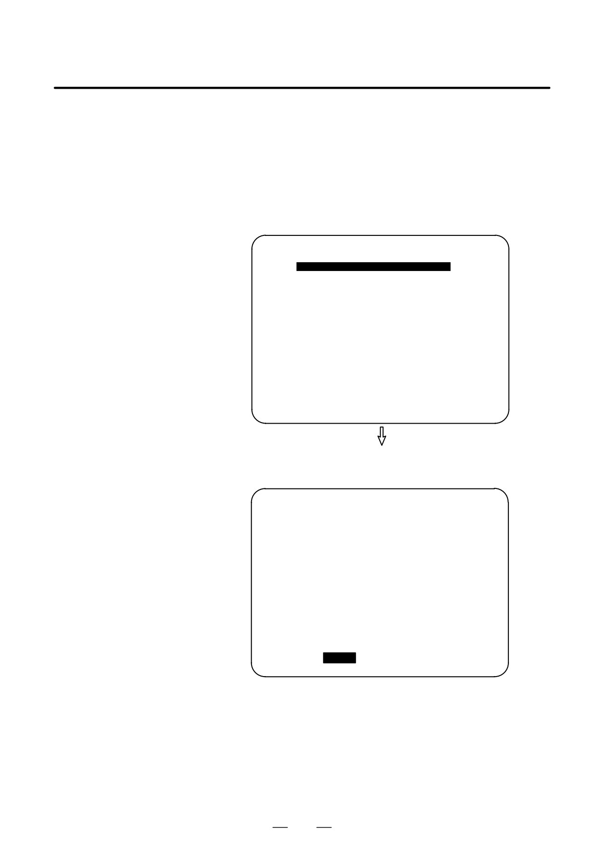
If machining time data is inserted into a program as shown below, the
program directory screen does not display the data or displays only part
of the data.
Example 1: Program directory screen when a program name
longer than 16 characters
PROGRAM
O0100 N00000
O0240 (SHAFT XSF301 MATERIAL=FC25)
(001H20M01S);
N10 G92 X100. Z10. ;
N20 S1500 M03 ;
N30 G00 X20.5 Z5. T0101 ;
N40 G01 Z-10. F25. ;
N50 G02 X16.5 Z-12. R2. ;
N60 G01 X40. ;
N70 X42. Z-13. ;
N80 Z-50. ;
N90 X44. Z-51. ;
EDIT
*** *** *** ***
16:52:13
[ INS-TM ]
[
]
[
]
[
]
[
]
All characters after the first 16 characters of the
program comment are discarded and the machining time
display field is left blank.
PROGRAM DIRECTORY
O0001 N00010
PROGRAM (NUM.) MEMORY (CHAR.)
USED:
60
3321
FREE:
2
429
O0240
(SHAFT XSF301
)
:
(
)
>_
EDIT **** *** ***
16:52:13
[ PRGRM ]
[
DIR
]
[
]
[
]
[ (OPRT) ]
1021
11. SETTING AND DISPLAYING DATA
OPERATION
B-63534EN/02
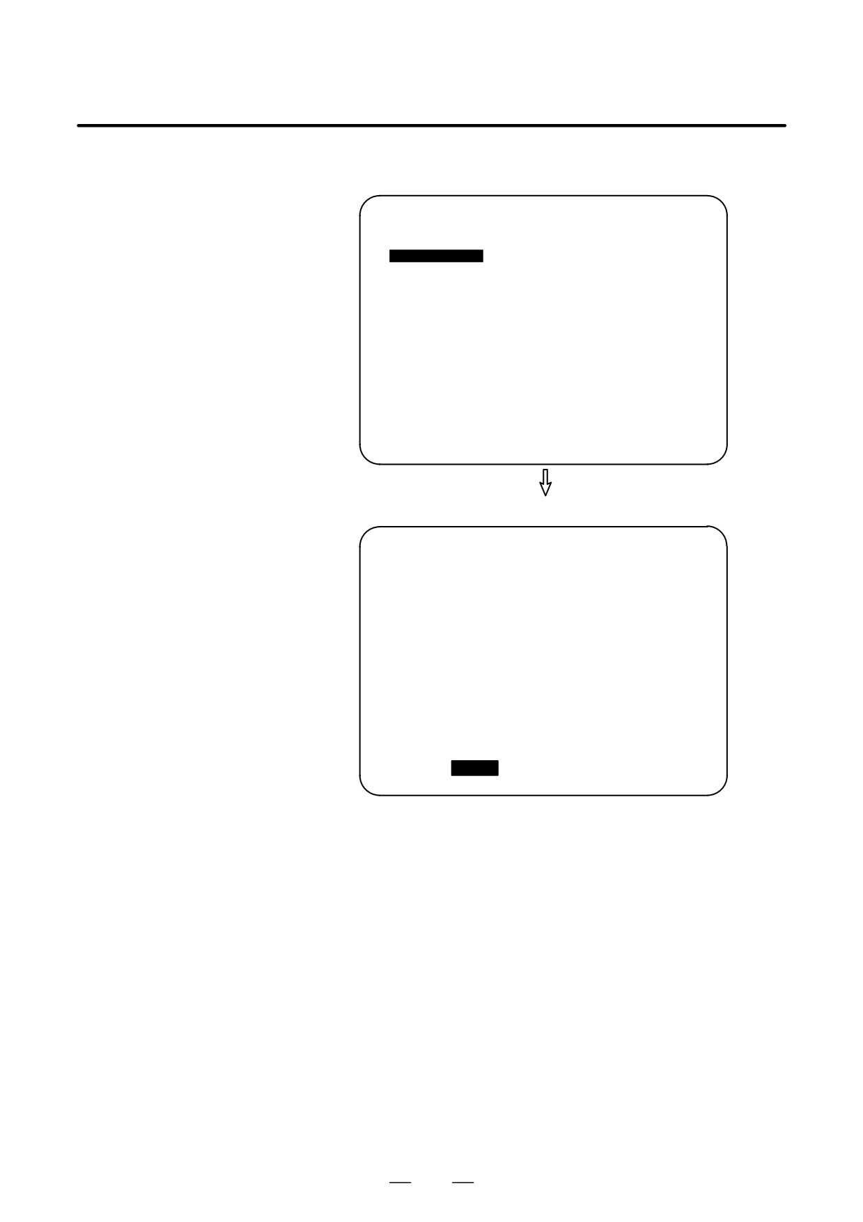
Example 2: Program directory screen when two or more machining
times are stamped.
PROGRAM
O0260 N00000
O0260 (SHAFT XSF302) (001H15M59S)
(001H20M01S) ;
N10 G92 X100. Z10. ;
N20 S1500 M03 ;
N30 G00 X20.5 Z5. T0101 ;
N40 G01 Z-10. F25. ;
N50 G02 X16.5 Z-12. R2. ;
N60 G01 X40. ;
N70 X42. Z-13. ;
N80 Z-50. ;
N90 X44. Z-51. ;
EDIT
*** *** *** ***
16:52:13
[ INS-TM ]
[
]
[
]
[
]
[
]
Only the first machining time is displayed.
PROGRAM DIRECTORY
O0001 N00010
PROGRAM (NUM.) MEMORY (CHAR.)
USED:
60
3321
FREE:
2
429
O0260
(SHAFT XSF302
)
:
(001H15M59S)
>_
EDIT **** *** ***
16:52:13
[ PRGRM ]
[
DIR
]
[
]
[
]
[ (OPRT) ]
1022
B-63534EN/02
OPERATION
11. SETTING AND DISPLAYING DATA
Example 3: Program directory screen when inserted machining time data
does not conform to the format hhhHmmMssS (3-digit
number followed by H, 2-digit number followed by M, and
2-digit number followed by S, in this order)
PROGRAM
O0280 N00000
O0280 (SHAFT XSF303) (1H10M59S)
N10 G92 X100. Z10. ;
N20 S1500 M03 ;
N30 G00 X20.5 Z5. T0101 ;
N40 G01 Z-10. F25. ;
N50 G02 X16.5 Z-12. R2. ;
N60 G01 X40. ;
N70 X42. Z-13. ;
N80 Z-50. ;
N90 X44. Z-51. ;
N100 X80. ;
EDIT
*** *** *** ***
16:52:13
[ INS-TM ]
[
]
[
]
[
]
[
]
The machining time display field is blank.
PROGRAM DIRECTORY
O0001 N00010
PROGRAM (NUM.) MEMORY (CHAR.)
USED:
60
3321
FREE:
2
429
O0260
(SHAFT XSF302
)
:
(001H15M59S)
O0280
(SHAFT XSF303
)
:
(
)
>_
EDIT **** *** ***
16:52:13
[ PRGRM ]
[
DIR
]
[
]
[
]
[
(OPRT) ]
D Correcting the
If an incorrect machining time is calculated (such as when a reset occurs
machining time
during program execution), reexecute the program to calculate the correct
machining time. If the machining time display screen displays multiple
programs with the same program number, select the machining time of the
latest program number for insertion into the program.
1023
11. SETTING AND DISPLAYING DATA
OPERATION
B-63534EN/02
This section describes the screens displayed by pressing function key
11.3
PROG
in the EDIT mode. Function key
PROG
in the EDIT mode can
SCREENS
DISPLAYED BY
display the program editing screen and the program list screen (displays
PROG
memory used and a list of programs). Pressing function key
PROG
in the
(IN THE EDIT MODE)
EDIT mode can also display the conversational graphics programming
screen and the floppy file directory screen. See III-9 and 10 for the
program editing screen and conversational graphics programming screen.
See III-8 for the floppy file directory screen.
11.3.1
Displays the number of registered programs, memory used, and a list of
registered programs.
Displaying Memory
Used and a List of
Programs
Procedure for displaying memory used and a list of programs
Procedure
1
Select the EDIT mode.
2
Press function key
PROG
3
Press chapter selection soft key [DIR].
PROGRAM DIRECTORY
O0001 N00010
PROGRAM (NUM.) MEMORY (CHAR.)
USED:
60
3321
FREE:
2
429
O0010 O0001 O0003 O0002 O0555 O0999
O0062 O0004 O0005 O1111 O0969 O6666
O0021 O1234 O0588 O0020 O0040
> _
S 0 T0000
MDI **** *** ***
16:05:59
[ PRGRM ]
[
DIR
]
[
]
[ C.A.P. ]
[ (OPRT) ]
1024
OPERATION
11. SETTING AND DISPLAYING DATA
B-63534EN/02
Explanations
D Details of memory used
PROGRAM NO. USED
PROGRAM NO. USED
: The number of the programs registered
(including the subprograms)
FREE
: The number of programs which can be
registered additionally.
MEMORY AREA USED
MEMORY AREA USED : The capacity of the program memory in which
data is registered (indicated by the number of
characters).
FREE
: The capacity of the program memory which
can be used additionally (indicated by the
number of characters).
D Program library list
Program Nos. registered are indicated.
Also, the program name can be displayed in the program table by setting
parameter NAM (No. 3107#0) to 1.
PROGRAM DIRECTORY
O0001 N00010
PROGRAM (NUM.) MEMORY (CHAR.)
USED:
60
3321
FREE:
2
429
O0001
(MACRO-GCODE.MAIN)
O0002
(MACRO-GCODE.SUB1)
O0010
(TEST-PROGRAM.ARTHMETIC NO.1)
O0020
(TEST-PROGRAM.F10-MACRO)
O0040
(TEST-PROGRAM.OFFSET)
O0050
O0100
(INCH/MM CONVERT CHECK NO.1)
O0200
(MACRO-MCODE.MAIN)
> _
EDIT **** *** ***
16:05:59
[ PRGRM ]
[
DIR
]
[
]
[ C.A.P.
]
[
(OPRT) ]
D Program name
Always enter a program name between the control out and control in
codes immediately after the program number.
Up to 31 characters can be used for naming a program within the
parentheses. If 31 characters are exceeded, the exceeded characters are
not displayed.
Only program number is displayed for the program without any program
name.
f
jjjj
(∆∆∆∆…∆)
;
Program number Program name (up to 31 characters)
D Order in which programs
Programs are displayed in the same order that they are registered in the
are displayed in the
program library list. However, if bit 4 (SOR) of parameter 3107 is set to
program library list
1, programs are displayed in the order of program number starting from
the smallest one.
1025
11. SETTING AND DISPLAYING DATA
OPERATION
B-63534EN/02
D Order in which programs
When no program has been deleted from the list, each program is
are registered
registered at the end of the list.
If some programs in the list were deleted, then a new program is
registered, the new program is inserted in the empty location in the list
created by the deleted programs.
Example) When bit 4 (SOR) of parameter 3107 is 0
1. After clearing all programs, register programs O0001, O0002, O0003,
O0004, and O0005 in this order. The program library list displays the
programs in the following order:
O0001, O0002, O0003, O0004, O0005
2. Delete O0002 and O0004. The program library list displays the
programs in the following order:
O0001, O0003, O0005
3. Register O0009. The program library list displays the programs in the
following order:
O0001, O0009, O0003, O0005
1026
OPERATION
11. SETTING AND DISPLAYING DATA
B-63534EN/02
11.3.2
In addition to the normal listing of the numbers and names of CNC
programs stored in memory, programs can be listed in units of groups,
Displaying a Program
according to the product to be machined, for example.
List for a Specified
Group
To assign CNC programs to the same group, assign names to those
programs, beginning each name with the same character string.
By searching through the program names for a specified character string,
the program numbers and names of all the programs having names
including that string are listed.
Procedure for Displaying a Program List for a Specified Group
Procedure
1
Enter EDIT or background editing mode.
2
Press the
PROG
function key.
3
Press the
PROG
function key or [DIR] soft key to display the program
list.
PROGRAM DIRECTORY
O0001 N00010
PROGRAM (NUM.) MEMORY (CHAR.)
USED:
60
3321
FREE:
2
429
O0020
(GEAR-1000 MAIN)
O0040
(GEAR-1000 SUB-1)
O0060
(SHAFT-2000 MAIN)
O0100
(SHAFT-2000 SUB-1)
O0200
(GEAR-1000 SUB-2)
O1000
(FRANGE-3000 MAIN)
O2000
(GEAR-1000 SUB-3)
O3000
(SHAFT-2000 SUB-2)
> _
EDIT **** *** *** ***
16:52:13
[ PRGRM ]
[
DIR
]
[
]
[
]
[
(OPRT) ]
4
Press the [(OPRT)] operation soft key.
BG-EDT O-SRH
GROUP
5
Press the [GROUP] operation soft key.
(NAME) PR-GRP
6
Press the [NAME] operation soft key.
7
Enter the character string corresponding to the group for which a
search is to be made, using the MDI keys. No restrictions are imposed
on the length of a program name. Note, however, that search is made
based on only the first 32 characters.
Example: To search for those CNC programs having names that
begin with character string “GEAR-1000,” enter the
following:
>GEAR-1000*_
1027
11. SETTING AND DISPLAYING DATA
OPERATION
B-63534EN/02
8
Pressing the [EXEC] operation soft key displays the group-unit
EXEC
program list screen, listing all those programs whose name includes
the specified character string.
PROGRAM DIRECTORY (GROUP) O0001 N00010
PROGRAM (NUM.) MEMORY (CHAR.)
USED:
60
3321
FREE:
2
429
O0020
(GEAR-1000 MAIN)
O0040
(GEAR-1000 SUB-1)
O0200
(GEAR-1000 SUB-2)
O2000
(GEAR-1000 SUB-3)
> _
EDIT **** *** *** ***
16:52:25
[ PRGRM ]
[
DIR
]
[
]
[
]
[
(OPRT) ]
[Group-unit program list screen displayed
when a search is made for “GEAR-1000*”]
When the program list consists of two or more pages, the pages can be
changed by using a page key.
Explanations
D * and ?
In the above example, the asterisk (*) must not be omitted. The asterisk
indicates an arbitrary character string (wild card specification).
“GEAR-1000*” indicates that the first nine characters of the target
program names must be “GEAR-1000,” followed by an arbitrary
character string. If only “GEAR-1000” is entered, a search is made only
for those CNC programs having the nine-character name “GEAR-1000.”
A question mark (?) can be used to specify a single arbitrary character.
For example, entering “????-1000” enables a search to be made for
programs having names which start with four arbitrary characters,
followed by “-1000”.
1028
OPERATION
11. SETTING AND DISPLAYING DATA
B-63534EN/02
[Example of using wild cards]
(Entered character string)
(Group for which the search will be made)
(a)
“*”
CNC programs having any name
(b)
“*ABC”
CNC programs having names which end
with “ABC”
(c)
“ABC*”
CNC programs having names which start
with “ABC”
(d)
“*ABC*”
CNC programs having names which
include “ABC”
(e)
“?A?C”
CNC programs having four-character
names, the second and fourth characters
of which are A and C, respectively
(f)
“??A?C”
CNC programs having five-character
names, the third and fifth characters of
which are A and C, respectively
(g)
“123*456”
CNC programs having names which start
with “123” and which end with “456”
D When the specified
If no program is located as a result of a search for an entered character
character string cannot
string, warning message “DATA NOT FOUND” is displayed on the
be found
program list screen.
D Holding the group for
A group-unit program list, generated by a search, is held until the power
which a search is made
is turned off or until another search is performed.
D Group for which
After changing the screen from the group-unit program list to another
previous search was
screen, pressing the [PR-GRP] operation soft key (displayed in step 6)
made
redisplays the group-unit program list screen, on which the program
names for the previously searched group are listed. Using this soft key
eliminates the need to enter the relevant character string again to redisplay
the search results after changing the screen.
Examples
Assume that the main programs and subprograms for machining gear part
number
1000 all have names which include character string
“GEAR-1000.” The numbers and names of those programs can be listed
by searching through the names of all CNC programs for character string
“GEAR-1000.” This function facilitates the management of the CNC
programs stored in large-capacity memory.
1029