FANUC Series 16i/160i/160is-MB, Series 18i/180i/180is-MB5, Series 18i/180i/180is-MB. Operator's Manual - page 31

8. DATA INPUT/OUTPUT
OPERATION
B-63534EN/02
8.5
OFFSET DATA INPUT
AND OUTPUT
8.5.1
Offset data is loaded into the memory of the CNC from a floppy or NC
tape. The input format is the same as for offset value output. See III- 8.5.2.
Inputting Offset Data
When an offset value is loaded which has the same offset number as an
offset number already registered in the memory, the loaded offset data
replaces existing data.
Inputting offset data
Procedure
1
Make sure the input device is ready for reading.
For the two-path control, select the tool post for which offset data to
be input is used with the tool post selection switch.
2
Press the EDIT switch on the machine operator’s panel.
3
When using a floppy, search for the required file according to the
procedure in III-8.2.
OFFSET
4
Press function key
SETTING
, then the tool compensation screen appears.
5
Press soft keys [(OPRT)].
6
Press rightmost soft key
(next menu key).
7
Press soft keys [READ] and [EXEC].
8
The input offset data will be displayed on the screen after completion
of input operation.
880

B-63534EN/02
OPERATION
8. DATA INPUT/OUTPUT
8.5.2
All offset data is output in a output format from the memory of the CNC
to a floppy or NC tape.
Outputting Offset Data
Outputting
offset data
Procedure
1
Make sure the output device is ready for output.
For the two-path control, select the tool post for which offset data to
be input is used with the tool post selection switch.
2
Specify the punch code system (ISO or EIA) using a parameter.
3
Press the EDIT switch on the machine operator’s panel.
OFFSET
4
Press function key
SETTING
, then the tool compensation screen appears.
5
Press soft key [(OPRT)].
6
Press the rightmost soft key
(next-menu key)
7
Press soft keys [PUNCH] and [EXEC].
Offset data is output in the output format described below.
Explanations
D Output format
Output format is as follows:
Format
(1) For tool compensation memory A
G10 G90 P_R_;
where P_: Offset No.
R_: Tool compensation amount
With OSI/Ethernet or DNC1/Ethernet, the output format is as
follows:
(2) For tool compensation memory B
Setting/changing the geometric compensation amount
G10 G90 L10 P_R_;
Setting/changing the wear compensation amount
G10 G90 L11 P_R_;
(3) For tool compensation memory C
Setting/changing the geometric compensation amount for H code
G10 G90 L10 P_R_;
Setting/changing the geometric compensation amount for D code
G10 G90 L12 P_R_;
Setting/changing the wear compensation amount for H code
G10 G90 L11 P_R_;
Setting/changing the wear compensation amount for D code
G10 G90 L13 P_R_;
The L1 command may be used instead of L11 for format compatibility of
the conventional CNC.
D Output file name
When the floppy disk directory display function is used, the name of the
output file is OFFSET.
881

8. DATA INPUT/OUTPUT
OPERATION
B-63534EN/02
8.6
Parameters and pitch error compensation data are input and output from
different screens, respectively. This chapter describes how to enter them.
INPUTTING AND
OUTPUTTING
PARAMETERS AND
PITCH ERROR
COMPENSATION
DATA
8.6.1
Parameters are loaded into the memory of the CNC unit from a floppy or
NC tape. The input format is the same as the output format. See III-8.6.2.
Inputting Parameters
When a parameter is loaded which has the same data number as a
parameter already registered in the memory, the loaded parameter
replaces the existing parameter.
Inputting parameters
Procedure
1
Make sure the input device is ready for reading.
For the two-path control, select the tool post for which parameters to
be input are used with the tool post selection switch.
2
When using a floppy, search for the required file according to the
procedure in III-8.2.
3
Press the EMERGENCY STOP button on the machine operator’s
panel.
OFFSET
4
Press function key
SETTING
5
Press the soft key [SETING] for chapter selection, then the setting
screen appears.
6
Enter 1 in response to the prompt for “PARAMETER WRITE
(PWE)” in setting data. Alarm P/S100 (indicating that parameters can
be written) appears.
7
Press soft key
SYSTEM
8
Press chapter selection soft key [PARAM], then the parameter screen
appears.
9
Press soft key [(OPRT)].
10
Press the rightmost soft key
(next-menu key).
11
Press soft keys [READ] and [EXEC].
Parameters are read into memory. Upon completion of input, the
“INPUT” indicator at the lower-right corner of the screen disappears.
OFFSET
12
Press function key
SETTING
13
Press soft key [SETING] for chapter selection.
14
Enter 0 in response to the prompt for “PARAMETER WRITE
(PWE)” in setting data.
882
B-63534EN/02
OPERATION
8. DATA INPUT/OUTPUT
15
Turn the power to the CNC back on.
16
Release the EMERGENCY STOP button on the machine operator’s
panel.
8.6.2
All parameters are output in the defined format from the memory of the
CNC to a floppy or NC tape.
Outputting Parameters
Outputting parameters
Procedure
1
Make sure the output device is ready for output.
For the two-path control, select the tool post for which parameters to
be input are used with the tool post selection switch.
2
Specify the punch code system (ISO or EIA) using a parameter.
3
Press the EDIT switch on the machine operator’s panel.
4
Press function key
SYSTEM
, then the parameter screen appears.
5
Press chapter selection soft key [PARAM].
6
Press soft key [(OPRT)].
7
Press rightmost soft key
(next-menu key).
8
Press soft keys [PUNCH].
9
To output all parameters, press the [ALL] soft key. To output only
parameters which are set to other than 0, press the [NON-0] soft key.
10
Press soft key [EXEC].
All parameters are output in the defined format.
Explanations
D Output format
Output format is as follows:
N . . . P
;
N . . . A1P . A2P . . AnP . .
;
N . . . P
;
N . . . : Parameter No.
A . . . : Axis No.(n is the number of control axis)
P . . . : Parameter setting value .
D Suppressing output of
To suppress the output of the following parameters, press the [PUNCH]
parameters set to 0
soft key then [NON-0] soft key.
Other than axis type
Axis type
Bit type
Parameter for which all bits
Parameter for an axis for
are set to 0
which all bits are set to 0.
Value type
Paramter whose value is 0.
Parameter for an axis for
which the value is 0.
883

8. DATA INPUT/OUTPUT
OPERATION
B-63534EN/02
D Output file name
When the floppy disk directory display function is used, the name of the
output file is PARAMETER.
Once all parameters have been output, the output file is named ALL
PARAMETER. Once only parameters which are set to other than 0 have
been output, the output file is named NON-0. PARAMETER.
Pitch error compensation data are loaded into the memory of the CNC
8.6.3
from a floppy or NC tape. The input format is the same as the output
Inputting Pitch Error
format. See III-8.6.4. When a pitch error compensation data is loaded
Compensation Data
which has the corresponding data number as a pitch error compensation
data already registered in the memory, the loaded data replaces the
existing data.
Pitch error compensation data
Procedure
1
Make sure the input device is ready for reading.
For the two-path control, select the tool post for which pitch error
compensation data to be input is used with the tool post selection
switch.
2
When using a floppy, search for the required file according to the
procedure in III-8.2.
3
Press the EMERGENCY STOP button on the machine operator’s
panel.
OFFSET
4
Press function key
SETTING
5
Press the soft key [SETING] for chapter selection.
6
Enter 1 in response to the prompt for writing parameters (PWE).
Alarm P/S100 (indicating that parameters can be written) appears.
7
Press soft key
SYSTEM
8
Press the rightmost soft key
(next-menu key)and press
chapter selection soft key [PITCH].
9
Press soft key [(OPRT)].
10
Press the rightmost soft key
(next-menu key).
11
Press soft keys [READ] and [EXEC].
Parameters are read into memory. Upon completion of input, the
“INPUT” indicator at the lower-right corner of the screen disappears.
OFFSET
12
Press function key
SETTING
13
Press soft key [SETING] for chapter selection.
14
Enter 0 in response to the prompt for “PARAMETER WRITE
(PWE)” in setting data.
884

B-63534EN/02
OPERATION
8. DATA INPUT/OUTPUT
15
Turn the power to the CNC back on.
16
Release the EMERGENCY STOP button on the machine operator’s
panel.
Explanations
D Pitch error
Parameters 3620 to 3624 and pitch error compensation data must be set
compensation
correctly to apply pitch error compensation correctly (See III-11.5.2).
8.6.4
All pitch error compensation data are output in the defined format from
the memory of the CNC to a floppy or NC tape.
Outputting Pitch Error
Compensation Data
Procedure for Outputting Pitch Error Compensation Data
1
Make sure the output device is ready for output.
For the two-path control, select the tool post for which pitch error
compensation data to be output is used with the tool post selection
switch.
2
Specify the punch code system (ISO or EIA) using a parameter.
3
Press the EDIT switch on the machine operator’s panel.
4
Press function key
SYSTEM
5
Press the rightmost soft key
(next-menu key) and press chapter
selection soft key [PITCH].
6
Press soft key [(OPRT)].
7
Press rightmost soft key
(next-menu key).
8
Press soft keys [PUNCH] and [EXEC].
All pitch error compensation data are output in the defined format.
Explanations
D Output format
Output format is as follows :
N10000 P
;
N11023 P
;
N : Pitch error compensation point + 10000
P : Pitch error compensation data
When bi-directional pitch error compensation is used, output format is
as follows :
N20000 P
;
N21023 P
;
N23000 P
;
N24023 P
;
N : Pitch error compensation point + 20000
P : Pitch error compensation data
D Output file name
When the floppy disk directory display function is used, the name of the
output file is “PITCH ERROR”.
885

8. DATA INPUT/OUTPUT
OPERATION
B-63534EN/02
8.7
INPUTTING/
OUTPUTTING
CUSTOM MACRO
COMMON
VARIABLES
The value of a custom macro common variable (#500 to #999) is loaded
8.7.1
into the memory of the CNC from a floppy or NC tape. The same format
Inputting Custom
used to output custom macro common variables is used for input. See
Macro Common
III-8.7.2. For a custom macro common variable to be valid, the input data
Variables
must be executed by pressing the cycle start button after data is input.
When the value of a common variable is loaded into memory, this value
replaces the value of the same common variable already existing (if any)
in memory.
Inputting custom macro common variables
Procedure
1
Register the program which has been output, as described in Section
III-8.7.2, in memory according to the program input procedure
described in Section III-8.4.1.
2
Press the MEMORY switch on the machine operator’s panel upon
completing input.
3
Press the cycle start button to execute the loaded program.
4
Display the macro vriable screen to chek whether the values of the
common variables have been set correctly.
Display of the macro variable screen
OFFSET
⋅ Press function key
SETTING
⋅ Press the rightmost soft key (next-menu key).
⋅ Press soft key [MACRO].
⋅ Select a variable with the page keys or numeric keys and
soft key [NO.SRH].
Explanations
D Common variables
The common variables (#500 to #531) can be input and output.
When the option for adding a common variable is specified, values from
#500 to #999 can be input and output.
#100 to #199 can be input and
output when bit 3 (PU5) of parameter No. 6001 is set to 1.
886

B-63534EN/02
OPERATION
8. DATA INPUT/OUTPUT
8.7.2
Custom macro common variables (#500 to #999) stored in the memory
of the CNC can be output in the defined format to a floppy or NC tape.
Outputting Custom
Macro Common
Variable
Outputting custom macro common variable
Procedure
1
Make sure the output device is ready for output.
2
Specify the punch code system (ISO or EIA) using a parameter.
3
Press the EDIT switch on the machine operator’s panel.
OFFSET
4
Press function key
SETTING
5
Press the rightmost soft key
(next-menu key), then press soft
key [MACRO].
6
Press soft key [(OPRT)].
7
Press the rightmost soft key
(next-menu key).
8
Press soft keys [PUNCH] and [EXEC].
Common variables are output in the defined format.
Explanations
D Output format
The output format is as follows:
%
;
#500=[25283*65536+65536]/134217728
(1)
#501=#0; .
(2)
#502=0; .
(3)
#503= .
;
;
;
#531= .
;
M02;
%
(1)The precision of a variable is maintained by outputting the value of the
variable as <expression>.
(2)Undefined variable
(3)When the value of a variable is 0
D Output file name
When the floppy disk directory display function is used, the name of the
output file is “MACRO VAR”.
D Common variable
The common variables (#500 to #531) can be input and output.
When the option for adding a common variable is specified, values from
#500 to #999 can be input and output.
#100 to #199 can be input and output when bit 3 (PU5) of parameter No.
6001 is set to 1.
887
8. DATA INPUT/OUTPUT
OPERATION
B-63534EN/02
On the floppy directory display screen, a directory of the FANUC Handy
8.8
File, FANUC Floppy Cassette, or FANUC FA Card files can be displayed.
DISPLAYING
In addition, those files can be loaded, output, and deleted.
DIRECTORY OF
FLOPPY CASSETTE
DIRECTORY (FLOPPY)
O0001 N00000
NO. FILE NAME
(METER) VOL
0001 PARAMETER
58.5
0002 O0001
1.9
0003 O0002
1.9
0004 O0010
1.3
0005 O0040
1.3
0006 O0050
1.9
0007 O0100
1.9
0008 O1000
1.9
0009 O9500
1.6
EDIT
****
***
***
11 : 51 : 12
PRGRM
DIR
(OPRT)
888
B-63534EN/02
OPERATION
8. DATA INPUT/OUTPUT
8.8.1
Displaying the
Directory
Displaying the directory of floppy cassette files
Procedure
1
Use the following procedure to display a directory of all the
files stored in a floppy:
1
Press the EDIT switch on the machine operator’s panel.
2
Press function key
PROG
3
Press the rightmost soft key
(next-menu key).
4
Press soft key [FLOPPY].
5
Press page key
or PAGE
PAGE
6
The screen below appears.
DIRECTORY (FLOPPY)
O0001 N00000
NO. FILE NAME
(METER) VOL
0001 PARAMETER
58.5
0002 O0001
1.9
0003 O0002
1.9
0004 O0010
1.3
0005 O0040
1.3
0006 O0050
1.9
0007 O0100
1.9
0008 O1000
1.9
0009 O9500
1.6
EDIT
****
***
***
11 : 53 : 04
F SRH
READ
PUNCH
DELETE
Fig. 8.8.1 (a)
7
Press a page key again to display another page of the directory.
889
8. DATA INPUT/OUTPUT
OPERATION
B-63534EN/02
Procedure 2
Use the following procedure to display a directory of files
starting with a specified file number :
1
Press the EDIT switch on the machine operator’s panel.
2
Press function key
PROG
3
Press the rightmost soft key
(next-menu key).
4
Press soft key [FLOPPY].
5
Press soft key [(OPRT)].
6
Press soft key [F SRH].
7
Enter a file number.
8
Press soft keys [F SET] and [EXEC].
9
Press a page key to display another page of the directory.
10
Press soft key [CAN] to return to the soft key display shown in the
screen of Fig 8.8.1 (a).
DIRECTORY (FLOPPY)
O0001 N00000
NO. FILE NAME
(METER) VOL
0005 O0040
1.3
0006 O0050
1.9
0007 O0100
1.9
0008 O1000
1.9
0009 O9500
1.6
SEARCH
FILE NO. =
>_
EDIT
****
***
***
11 : 54 : 19
F SET
CAN
EXEC
Fig. 8.8.1 (b)
890
B-63534EN/02
OPERATION
8. DATA INPUT/OUTPUT
Explanations
D Screen fields and their
NO :Displays the file number
meanings
FILE NAME: Displays the file name.
(METER)
: Converts and prints out the file capacity to paper tape
length.You can also produce H
(FEET)
I by setting the INPUT UNIT to INCH of the setting data.
VOL.
: When the file is multi-volume, that state is displayed.
(Ex.) Floppy or card A
Floppy or card B
Floppy or card C
C01
C02
L03
C(number)means CONTINUE
L(number)means LAST
number number of floppies or cards
891
8. DATA INPUT/OUTPUT
OPERATION
B-63534EN/02
8.8.2
The contents of the specified file number are read to the memory of NC.
Reading Files
Reading files
Procedure
1
Press the EDIT switch on the machine operator’s panel.
For the two-path control, select the tool post for which a file is to be
input in memory with the tool post selection switch.
2
Press function key
PROG
3
Press the rightmost soft key
(next-menu key).
4
Press soft key [FLOPPY].
5
Press soft key [(OPRT)].
6
Press soft key [READ].
DIRECTORY (FLOPPY)
O0001 N00000
NO. FILE NAME
(METER) VOL
0001 PARAMETER
58.5
0002 O0001
1.9
0003 O0002
1.9
0004 O0010
1.3
0005 O0040
1.3
0006 O0050
1.9
0007 O0100
1.9
0008 O1000
1.9
0009 O9500
1.6
READ
FILE NO. =
PROGRAM NO. =
>_
EDIT
****
***
***
11 : 55 : 04
F SET
O SET
STOP
CAN
EXEC
7
Enter a file number.
8
Press soft key [F SET].
9
To modify the program number, enter the program number, then press
soft key [O SET].
10
Press soft key [EXEC]. The file number indicated in the lower-left
corner of the screen is automatically incremented by one.
11
Press soft key [CAN] to return to the soft key display shown in
the screen of Fig. 8.8.1.(a).
892
B-63534EN/02
OPERATION
8. DATA INPUT/OUTPUT
8.8.3
Any program in the memory of the CNC unit can be output to a floppy
as a file.
Outputting Programs
Outputting programs
Procedure
1
Press the EDIT switch on the machine operator’s panel.
For the two-path control, select the tool post for which a file is to be
input in memory with the tool post selection switch.
2
Press function key
PROG
3
Press the rightmost soft key
(next-menu key).
4
Press soft key [FLOPPY].
5
Press soft key [(OPRT)].
6
Press soft key [PUNCH].
DIRECTORY (FLOPPY)
O0002 N01000
NO. FILE NAME
(METER) VOL
0001 PARAMETER
58.5
0002 O0001
1.9
0003 O0002
1.9
0004 O0010
1.3
0005 O0040
1.3
0006 O0050
1.9
0007 O0100
1.9
0008 O1000
1.9
0009 O9500
1.6
PUNCH
FILE NO. =
PROGRAM NO. =
>_
EDIT
****
***
***
11 : 55 : 26
F SET
O SET
STOP
CAN
EXEC
7
Enter a program number. To write all programs into a single file, enter
-9999 in the program number field. In this case, the file name
“ALL.PROGRAM” is registered.
8
Press soft key [O SET].
9
Press soft key [EXEC]. The program or programs specified in step 7
are written after the last file on the floppy. To output the program after
deleting files starting with an existing file number, key in the file
number, then press soft key [F SET] followed by soft key [EXEC].
10
Press soft key [CAN] to return to the soft key display shown in
the screen of Fig. 8.8.1 (a).
893
8. DATA INPUT/OUTPUT
OPERATION
B-63534EN/02
8.8.4
The file with the specified file number is deleted.
Deleting Files
Deleting files
Procedure
1
Press the EDIT switch on the machine operator’s panel.
2
Press function key
PROG
3
Press the rightmost soft key
(next-menu key).
4
Press soft key [FLOPPY].
5
Press soft key [(OPRT)].
6
Press soft key [DELETE].
DIRECTORY (FLOPPY)
O0001 N00000
NO. FILE NAME
(METER) VOL
0001 PARAMETER
58.5
0002 O0001
1.9
0003 O0002
1.9
0004 O0010
1.3
0005 O0040
1.3
0006 O0050
1.9
0007 O0100
1.9
0008 O1000
1.9
0009 O9500
1.6
DELETE
FILE NO. =
NAME=
>_
EDIT
****
***
***
11 : 55 : 51
F SET
F
NAME
CAN
EXEC
7
Specify the file to be deleted.
When specifying the file with a file number, type the number and
press soft key [F SET]. When specifying the file with a file name,
type the name and press soft key [F NAME].
8
Press soft key [EXEC].
The file specified in the file number field is deleted. When a file is
deleted, the file numbers after the deleted file are each decremented
by one.
9
Press soft key [CAN] to return to the soft key display shown in
the screen of Fig. 8.8.1 (a).
894
B-63534EN/02
OPERATION
8. DATA INPUT/OUTPUT
Restrictions
D Inputting file numbers
If
[F SET] or [O SET] is pressed without key inputting file number and
and program numbers
program number, file number or program number shows blank. When
with keys
0 is entered for file numbers or program numbers, 1 is displayed.
D I/O devices
To use channel 0 ,set a device number in parameter (No. 102).
Set the I/O device number to parameter (No. 112) when cannel 1 is used.
Set it to (No. 0122) when channel 2 is used.
D Significant digits
For the numeral input in the data input area with FILE No. and
PROGRAM No., only lower 4 digits become valid.
D Collation
When the data protection key on the machine operator’s panel
is ON, no programs are read from the floppy. They are verified against
the contents of the memory of the CNC instead.
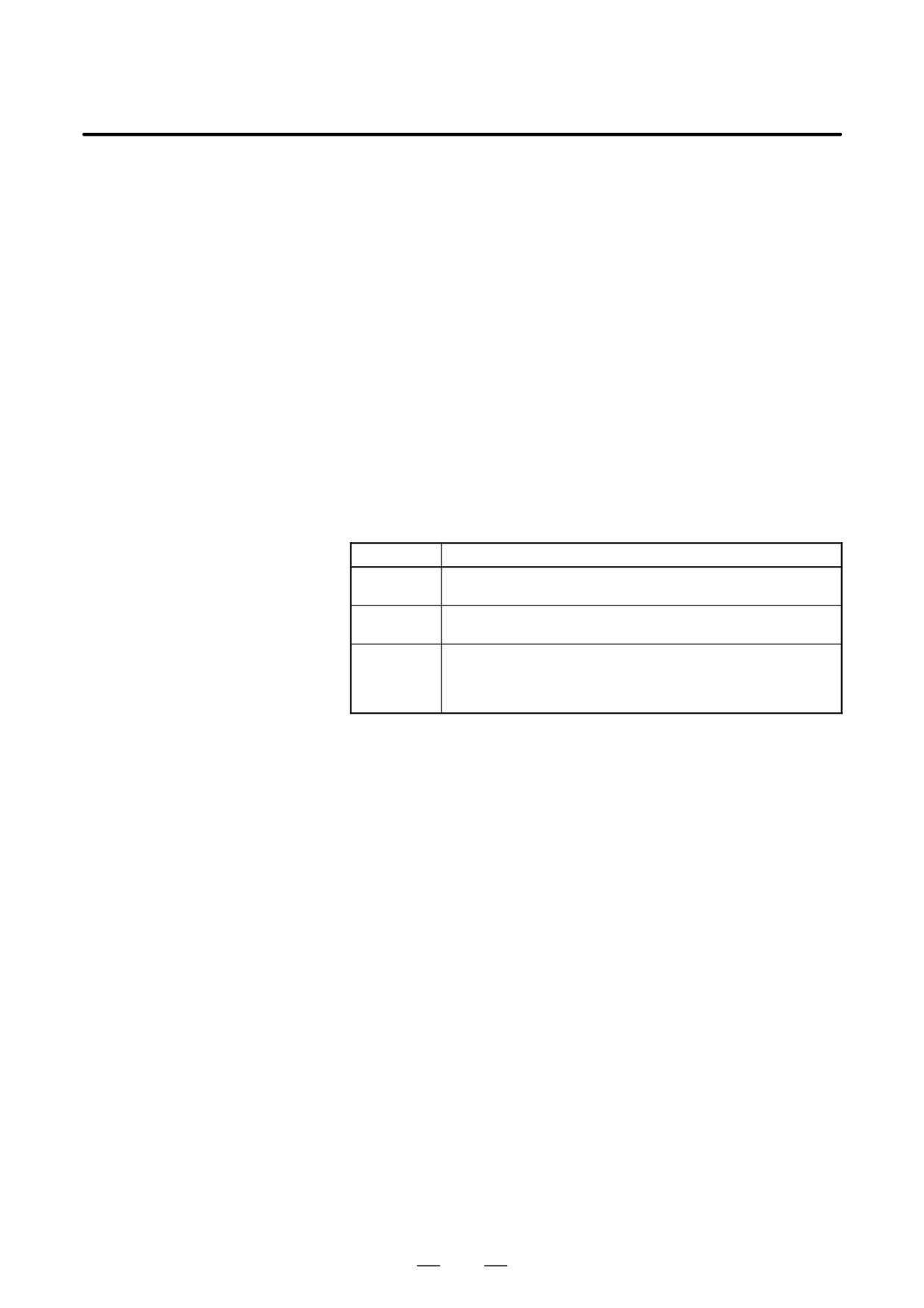
ALARM
Alarm No.
Contents
An invalid file number or program number was entered.
71
(Specified program number is not found.)
Verification operation found a mismatch between a program
79
loaded into memory and the contents of the floppy
The dataset-ready signal (DR) for the input/output device is
turned off. (The no file error or duplicate file error occurred on
86
the input/output device because an invalid file number, pro-
gram number, or file name was entered.
895
8. DATA INPUT/OUTPUT
OPERATION
B-63534EN/02
8.9
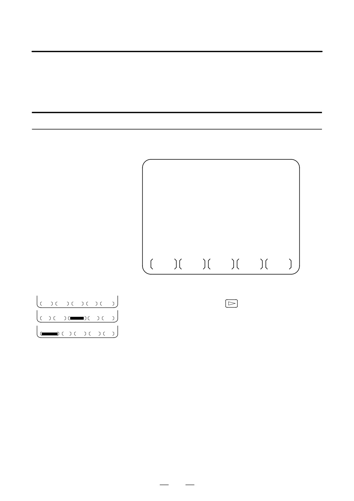
CNC programs stored in memory can be grouped according to their
names, thus enabling the output of CNC programs in group units. Section
OUTPUTTING A
III-11.3.2 explains the display of a program listing for a specified group.
PROGRAM LIST FOR
A SPECIFIED GROUP
Procedure for Outputting a Program List for a Specified Group
Procedure
1
Display the program list screen for a group of programs, as described
in Section III-11.3.2.
PROGRAM DIRECTORY (GROUP)
O0001 N00010
PROGRAM (NUM.)
MEMORY (CHAR.)
USED:
60
3321
FREE:
2
429
O0020 (GEAR-1000 MAIN
)
O0040 (GEAR-1000 SUB-1
)
O0200 (GEAR-1000 SUB-2
)
O2000 (GEAR-1000 SUB-3
)
>_
EDIT
****
***
***
***
16 : 52 : 13
PRGRM
DIR
(OPRT)
2
Press the [(OPRT)] operation soft key.
BG-EDT O-SRH
GROUP
3
Press the right-most soft key
(continuous menu key).
READ
PUNCH
4
Press the [PUNCH] operation soft key.
5
Press the [AL-GRP] operation soft key.
AL-GRP
STOP
CAN EXEC
The CNC programs in the group for which a search is made are
output. When these programs are output to a floppy disk, they are
output to a file named GROUP.PROGRAM.
896
B-63534EN/02
OPERATION
8. DATA INPUT/OUTPUT
8.10
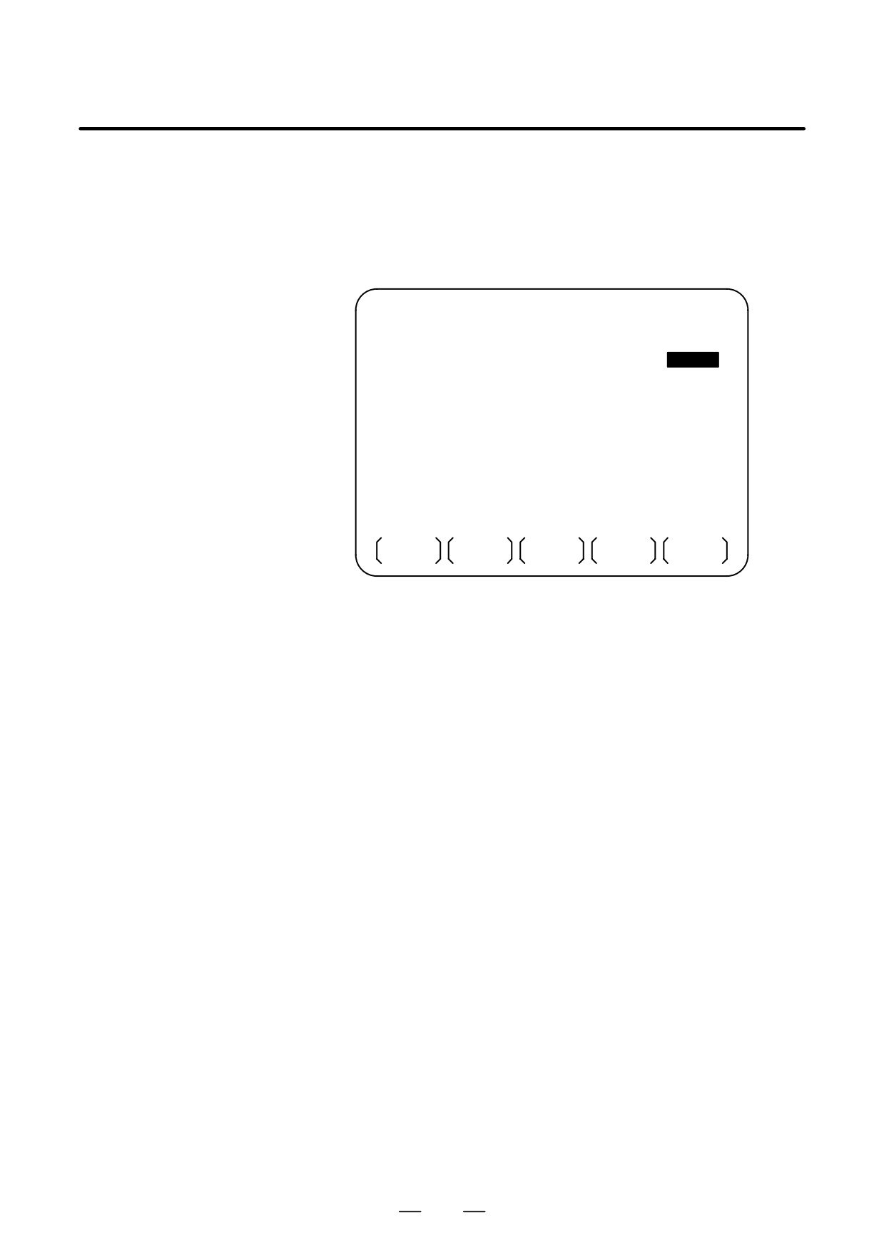
To input/output a particular type of data, the corresponding screen is
usually selected. For example, the parameter screen is used for parameter
DATA INPUT/OUTPUT
input from or output to an external input/output unit, while the program
ON THE ALL IO
screen is used for program input or output. However, programs,
SCREEN
parameters, offset data, and macro variables can all be input and output
using a single common screen, that is, the ALL IO screen.
READ/PUNCH (PROGRAM)
O1234 N12345
I/O CHANNEL
3
TV CHECK
OFF
DEVICE NUM.
0
PUNCH CODE
ISO
BAUDRATE
4800
INPUT CODE
ASCII
STOP BIT
2
FEED OUTPUT
FEED
NULL INPUT (EIA)
NO
EOB OUTPUT (ISO) CR
TV CHECK (NOTES)
ON
BAUDRATE CLK. INNER
CD CHECK (232C)
OFF
RESET/ALARM
ON
PARITY BIT
OFF
SAT COMMAND HOST
INTERFACE
RS422
COM PROTCOL
A
END CODE
EXT
COM CODE
ASCII
(0:EIA
1:ISO)>1_
MDI
****
***
***
***
12:34:56
PRGRM
PARAM
OFFSET
MACRO
(OPRT)
Fig. 8.10 ALL IO screen (when channel 3 is being
used for input/output)
897
8. DATA INPUT/OUTPUT
OPERATION
B-63534EN/02
8.10.1
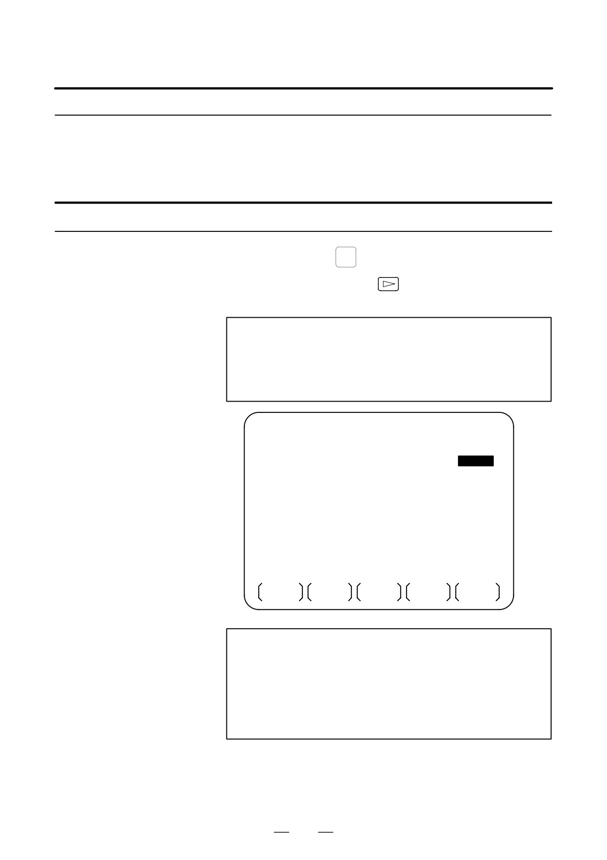
Input/output-related parameters can be set on the ALL IO screen.
Parameters can be set, regardless of the mode.
Setting
Input/Output-Related
Parameters
Setting input/output-related parameters
Procedure
1
Press function key
SYSTEM
2
Press the rightmost soft key
(next-menu key) several times.
3
Press soft key [ALL IO] to display the ALL IO screen.
NOTE
1
If program or floppy is selected in EDIT mode, the program
directory or floppy screen is displayed.
2
When the power is first turned on, program is selected by
default.
READ/PUNCH (PROGRAM)
O1234 N12345
I/O CHANNEL
3
TV CHECK
OFF
DEVICE NUM.
0
PUNCH CODE
ISO
BAUDRATE
4800
INPUT CODE
ASCII
STOP BIT
2
FEED OUTPUT
FEED
NULL INPUT (EIA)
NO
EOB OUTPUT (ISO) CR
TV CHECK (NOTES)
ON
BAUDRATE CLK. INNER
CD CHECK (232C)
OFF
RESET/ALARM
ON
PARITY BIT
OFF
SAT COMMAND HOST
INTERFACE
RS422
COM PROTCOL
A
END CODE
EXT
COM CODE
ASCII
(0:EIA
1:ISO)>1_
MDI
****
***
***
***
12:34:56
PRGRM
PARAM
OFFSET
MACRO
(OPRT)
NOTE
Baud rate clock, CD check (232C), reset/alarm report, and
the parity bit for parameter No.
134, as well as the
communication code, end code, communication protocol,
interface, and SAT command for parameter No. 135 are
displayed only when channel
3 is being used for
input/output.
4
Select the soft key corresponding to the desired type of data (program,
parameter, and so forth).
5
Set the parameters corresponding to the type of input/output unit to be
used.
(Parameter setting is possible regardless of the mode.)
898
B-63534EN/02
OPERATION
8. DATA INPUT/OUTPUT
8.10.2
A program can be input and output using the ALL IO screen.
When entering a program using a cassette or card, the user must specify
Inputting and
the input file containing the program (file search).
Outputting Programs
File search
Procedure
1
Press soft key [PRGRM] on the ALL IO screen, described in Section
8.10.1.
2
Select EDIT mode. A program directory is displayed.
3
Press soft key [(OPRT)]. The screen and soft keys change as shown
below.
⋅
A program directory is displayed only in EDIT mode. In all other
modes, the ALL IO screen is displayed.
O0001 N00010
PROGRAM (NUM.)
MEMORY (CHAR.)
USED
:
60
3321
FREE
:
2
429
O0010 O0001 O0003 O0002 O0555 O0999
O0062 O0004 O0005 O1111 O0969 O6666
O0021 O1234 O0588 O0020 O0040
>_
EDIT
****
***
***
***
14:46:09
F SRH
READ
PUNCH
DELETE
(OPRT)
4
Enter address N.
5
Enter the number of the file to be found.
⋅
N0
The first floppy file is found.
⋅
One of N1 to N9999
Among the files numbered from 1 to 9999, a specified file is found.
⋅
N-9999
The file immediately after that used most recently is found.
⋅
N-9998
When -9998 is specified, the next file is found. Then, each time
a file input/output operation is performed, N-9999 is automatically
inserted. This means that subsequent files can be sequentially
found automatically.
This state is canceled by specifying N0, N1 to N9999, or N-9999,
or upon a reset.
899
8. DATA INPUT/OUTPUT
OPERATION
B-63534EN/02
6
Press soft keys [F SRH] and [EXEC].
CAN EXEC
The specified file is found.
Explanations
D Difference between N0
When a file already exists in a cassette or card, specifying N0 or N1 has
and N1
the same effect. If N1 is specified when there is no file on the cassette or
card, an alarm is issued because the first file cannot be found. Specifying
N0 places the head at the start of the cassette or card, regardless of whether
the cassette/card already contains files. So, no alarm is issued in this case.
N0 can be used, for example, when a program is written into a new
cassette or card, or when a previously used cassette or card is used once
all the files it contains have been erased.
D Alarm issue during file
If an alarm (file search failure, for example) is generated during file
search
search, the CNC does not issue an alarm immediately. However, a P/S
alarm (No. 086) is issued if input/output is subsequently performed on
that file.
Instead of sequentially searching for files by specifying actual file
D File search using N-9999
numbers every time, the user can specify the first file number, then find
the subsequent files by specifying N-9999. When N-9999 is specified,
the time required for file search can be reduced.
900
B-63534EN/02
OPERATION
8. DATA INPUT/OUTPUT
Inputting a program
Procedure
1
Press soft key [PRGRM] on the ALL IO screen, described in Section
8.10.1.
2
Select EDIT mode. A program directory is displayed.
3
Press soft key [(OPRT)]. The screen and soft keys change as shown
below.
⋅
A program directory is displayed only in EDIT mode. In all other
modes, the ALL IO screen is displayed.
O0001 N00010
PROGRAM (NUM.)
MEMORY (CHAR.)
USED
:
60
3321
FREE
:
2
429
O0010 O0001 O0003 O0002 O0555 O0999
O0062 O0004 O0005 O1111 O0969 O6666
O0021 O1234 O0588 O0020 O0040
>_
EDIT
****
***
***
***
14:46:09
F SRH
READ
PUNCH
DELETE
(OPRT)
4
To specify a program number to be assigned to an input program,
enter address O, followed by the desired program number.
If no program number is specified, the program number in the file or
on the NC tape is assigned as is.
5
Press soft key [READ], then [EXEC].
STOP CAN EXEC
The program is input with the program number specified in step 4
assigned.
To cancel input, press soft key [CAN].
To stop input prior to its completion, press soft key [STOP].
901
8. DATA INPUT/OUTPUT
OPERATION
B-63534EN/02
Outputting programs
Procedure
1
Press soft key [PRGRM] on the ALL IO screen, described in Section
8.10.1.
2
Select EDIT mode. A program directory is displayed.
3
Press soft key [(OPRT)]. The screen and soft keys change as shown
below.
⋅
A program directory is displayed only in EDIT mode. In all other
modes, the ALL IO screen is displayed.
O0001 N00010
PROGRAM (NUM.)
MEMORY (CHAR.)
USED
:
60
3321
FREE
:
2
429
O0010 O0001 O0003 O0002 O0555 O0999
O0062 O0004 O0005 O1111 O0969 O6666
O0021 O1234 O0588 O0020 O0040
>_
EDIT
****
***
***
***
14:46:09
F SRH
READ
PUNCH
DELETE
(OPRT)
4
Enter address O.
5
Enter a desired program number.
If -9999 is entered, all programs in memory are output.
To output a range of programs, enter O∆∆∆∆, OVVVV.. The
programs numbered from ∆∆∆∆ to VVVV are output.
When bit 4 (SOR) of parameter No. 3107 for sorted display is set to 1
on the program library screen, programs are output in order, starting
from those having the smallest program numbers.
6
Press soft key [PUNCH], then [EXEC].
STOP CAN EXEC
The specified program or programs are output. If steps 4 and 5 are
omitted, the currently selected program is output.
To cancel output, press soft key [CAN].
To stop output prior to its completion, press soft key [STOP].
902
B-63534EN/02
OPERATION
8. DATA INPUT/OUTPUT
Deleting files
Procedure
1
Press soft key [PRGRM] on the ALL IO screen, described in Section
8.10.1.
2
Select EDIT mode. A program directory is displayed.
3
Press soft key [(OPRT)]. The screen and soft keys change as shown
below.
⋅
A program directory is displayed only in EDIT mode. In all other
modes, the ALL IO screen is displayed.
O0001 N00010
PROGRAM (NUM.)
MEMORY (CHAR.)
USED
:
60
3321
FREE
:
2
429
O0010 O0001 O0003 O0002 O0555 O0999
O0062 O0004 O0005 O1111 O0969 O6666
O0021 O1234 O0588 O0020 O0040
>_
EDIT
****
***
***
***
14:46:09
F SRH
READ
PUNCH
DELETE
(OPRT)
4
Press soft key [DELETE].
5
Enter a file number, from 1 to 9999, to indicate the file to be deleted.
6
Press soft key [EXEC].
CAN EXEC
The k-th file, specified in step 5, is deleted.
Explanations
D File numbers after
After deletion of the k-th file, the previous file numbers (k+1) to n are
deletion
decremented by 1 to k to (n-1).
Before deletion
After deletion
1 to (k-1)
1 to (k-1)
K
Delete
(k+1) to n
k to (n-1)
D Write protect
Before a file can be deleted, the write protect switch of the cassette must
be set to make the cassette writable.
903
8. DATA INPUT/OUTPUT
OPERATION
B-63534EN/02
8.10.3
Parameters can be input and output using the ALL IO screen.
Inputting and
Outputting Parameters
Inputting parameters
Procedure
1
Press soft key [PARAM] on the ALL IO screen, described in Section
8.10.1.
2
Select EDIT mode.
3
Press soft key [(OPRT)]. The screen and soft keys change as shown
below.
READ/PUNCH (PARAMETER)
O1234 N12345
I/O CHANNEL
3
TV CHECK
OFF
DEVICE NUM.
0
PUNCH CODE
ISO
BAUDRATE
4800
INPUT CODE
ASCII
STOP BIT
2
FEED OUTPUT
FEED
NULL INPUT (EIA)
NO
EOB OUTPUT (ISO) CR
TV CHECK (NOTES)
ON
BAUDRATE CLK. INNER
CD CHECK (232C)
OFF
RESET/ALARM
ON
PARITY BIT
OFF
COM CODE
ASCII
END CODE
EXT
COM PROTCOL
A
INTERFACE
RS422
SAT COMMAND HOST
(0:EIA 1:ISO)>1_
MDI
****
***
***
***
12:34:56
READ
PUNCH
4
Press soft key [READ], then [EXEC].
CAN EXEC
The parameters are read, and the ”INPUT” indicator blinks at the
lower-right corner of the screen. Upon the completion of input, the
”INPUT” indicator is cleared from the screen.
To cancel input, press soft key [CAN].
904
B-63534EN/02
OPERATION
8. DATA INPUT/OUTPUT
Outputting parameters
Procedure
1
Press soft key [PARAM] on the ALL IO screen, described in Section
8.10.1.
2
Select EDIT mode.
3
Press soft key [(OPRT)]. The screen and soft keys change as shown
below.
READ/PUNCH (PARAMETER)
O1234 N12345
I/O CHANNEL
3
TV CHECK
OFF
DEVICE NUM.
0
PUNCH CODE
ISO
BAUDRATE
4800
INPUT CODE
ASCII
STOP BIT
2
FEED OUTPUT
FEED
NULL INPUT (EIA)
NO
EOB OUTPUT (ISO) CR
TV CHECK (NOTES)
ON
BAUDRATE CLK. INNER
CD CHECK (232C)
OFF
RESET/ALARM
ON
PARITY BIT
OFF
COM CODE
ASCII
END CODE
EXT
COM PROTCOL
A
INTERFACE
RS422
SAT COMMAND HOST
(0:EIA 1:ISO)>1_
MDI
****
***
***
***
12:34:56
READ
PUNCH
4
Press soft key [PUNCH], then [EXEC].
CAN EXEC
The parameters are output, and the ”OUTPUT” indicator blinks at the
lower-right corner of the screen. Upon the completion of output, the
”OUTPUT” indicator is cleared from the screen.
To cancel output, press soft key [CAN].
905
8. DATA INPUT/OUTPUT
OPERATION
B-63534EN/02
8.10.4
Offset data can be input and output using the ALL IO screen.
Inputting and
Outputting Offset Data
Inputting offset data
Procedure
1
Press soft key [OFFSET] on the ALL IO screen, described in Section
8.10.1.
2
Select EDIT mode.
3
Press soft key [(OPRT)]. The screen and soft keys change as shown
below.
READ/PUNCH (OFFSET)
O1234 N12345
I/O CHANNEL
3
TV CHECK
OFF
DEVICE NUM.
0
PUNCH CODE
ISO
BAUDRATE
4800
INPUT CODE
ASCII
STOP BIT
2
FEED OUTPUT
FEED
NULL INPUT (EIA)
NO
EOB OUTPUT (ISO) CR
TV CHECK (NOTES)
ON
BAUDRATE CLK. INNER
CD CHECK (232C)
OFF
RESET/ALARM
ON
PARITY BIT
OFF
COM CODE
ASCII
END CODE
EXT
COM PROTCOL
A
INTERFACE
RS422
SAT COMMAND HOST
(0:EIA 1:ISO)>1_
MDI
****
***
***
***
12:34:56
READ
PUNCH
4
Press soft key [READ], then [EXEC].
CAN EXEC
The offset data is read, and the ”INPUT” indicator blinks at the
lower-right corner of the screen.
Upon the completion of input, the ”INPUT” indicator is cleared from
the screen.
To cancel input, press soft key [CAN].
906
B-63534EN/02
OPERATION
8. DATA INPUT/OUTPUT
Outputting offset data
Procedure
1
Press soft key [OFFSET] on the ALL IO screen, described in Section
8.10.1.
2
Select EDIT mode.
3
Press soft key [(OPRT)]. The screen and soft keys change as shown
below.
READ/PUNCH (OFFSET)
O1234 N12345
I/O CHANNEL
3
TV CHECK
OFF
DEVICE NUM.
0
PUNCH CODE
ISO
BAUDRATE
4800
INPUT CODE
ASCII
STOP BIT
2
FEED OUTPUT
FEED
NULL INPUT (EIA)
NO
EOB OUTPUT (ISO) CR
TV CHECK (NOTES)
ON
BAUDRATE CLK. INNER
CD CHECK (232C)
OFF
RESET/ALARM
ON
PARITY BIT
OFF
COM CODE
ASCII
END CODE
EXT
COM PROTCOL
A
INTERFACE
RS422
SAT COMMAND HOST
(0:EIA 1:ISO)>1_
MDI
****
***
***
***
12:34:56
READ
PUNCH
4
Press soft key [PUNCH], then [EXEC].
CAN EXEC
The offset data is output, and the ”OUTPUT” indicator blinks at the
lower-right corner of the screen. Upon the completion of output, the
”OUTPUT” indicator is cleared from the screen.
To cancel output, press soft key [CAN].
907
8. DATA INPUT/OUTPUT
OPERATION
B-63534EN/02
8.10.5
Custom macro common variables can be output using the ALL IO screen.
Outputting Custom
Macro Common
Variables
Outputting custom macro common variables
Procedure
1
Press soft key [MACRO] on the ALL IO screen, described in Section
8.10.1.
2
Select EDIT mode.
3
Press soft key [(OPRT)]. The screen and soft keys change as shown
below.
READ/PUNCH (MACRO)
O1234 N12345
I/O CHANNEL
3
TV CHECK
OFF
DEVICE NUM.
0
PUNCH CODE
ISO
BAUDRATE
4800
INPUT CODE
ASCII
STOP BIT
2
FEED OUTPUT
FEED
NULL INPUT (EIA)
NO
EOB OUTPUT (ISO) CR
TV CHECK (NOTES)
ON
BAUDRATE CLK. INNER
CD CHECK (232C)
OFF
RESET/ALARM
ON
PARITY BIT
OFF
COM CODE
ASCII
END CODE
EXT
COM PROTCOL
A
INTERFACE
RS422
SAT COMMAND HOST
(0:EIA 1:ISO)>1_
MDI
****
***
***
***
12:34:56
READ
PUNCH
4
Press soft key [PUNCH], then [EXEC].
CAN EXEC
The custom macro common variables are output, and the ”OUTPUT”
indicator blinks at the lower-right corner of the screen. Upon the
completion of output, the ”OUTPUT” indicator is cleared from the
screen.
To cancel output, press soft key [CAN].
NOTE
To input a macro variable, read the desired custom macro
statement as a program, then execute the program.
908
B-63534EN/02
OPERATION
8. DATA INPUT/OUTPUT
8.10.6
The ALL IO screen supports the display of a directory of floppy files, as
well as the input and output of floppy files.
Inputting and
Outputting Floppy
Files
Displaying a file directory
Procedure
1
Press the rightmost soft key
(next-menu key) on the ALL IO
screen, described in Section 8.10.1.
2
Press soft key [FLOPPY].
3
Select EDIT mode. The floppy screen is displayed.
4
Press soft key [(OPRT)]. The screen and soft keys change as shown
below.
The floppy screen is displayed only in EDIT mode. In all other
modes, the ALL IO screen is displayed.
READ/PUNCH (FLOPPY)
O1234 N12345
>
MDI
****
***
***
***
12:34:56
F SRH
READ
PUNCH
DELETE
5
Press soft key [F SRH].
6
Enter the number of the desired file, then press soft key [F SET].
F SET
CAN EXEC
7
Press soft key [EXEC]. A directory is displayed, with the specified
file uppermost. Subsequent files in the directory can be displayed by
pressing the page key.
909