FANUC Series 16i/160i/160is-MB, Series 18i/180i/180is-MB5, Series 18i/180i/180is-MB. Operator's Manual - page 30
5. TEST OPERATION
OPERATION
B-63534EN/02
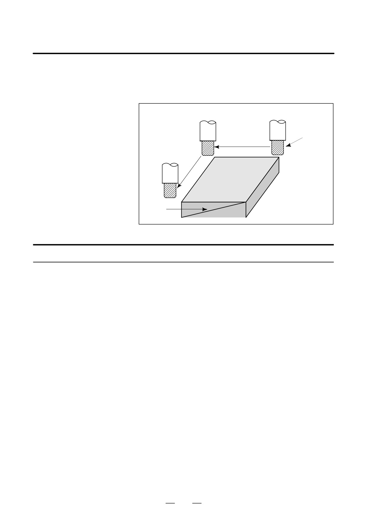
Pressing the single block switch starts the single block mode. When the
5.5
cycle start button is pressed in the single block mode, the tool stops after
SINGLE BLOCK
a single block in the program is executed. Check the program in the single
block mode by executing the program block by block.
Cycle start
Cycle start
Tool
Cycle start
Stop
Stop
Workpiece
Stop
Fig. 5.5 (a) Single block
Procedure for Single block
Procedure
1
Press the single block switch on the machine operator’s panel. The
execution of the program is stopped after the current block is
executed.
2
Press the cycle start button to execute the next block. The tool stops
after the block is executed.
Refer to the appropriate manual provided by the machine tool builder
for single block execution.
850
B-63534EN/02
OPERATION
5. TEST OPERATION
Explanation
D Reference position
If G28 to G30 are issued, the single block function is effective at the
return and single block
intermediate point.
D Single block during a
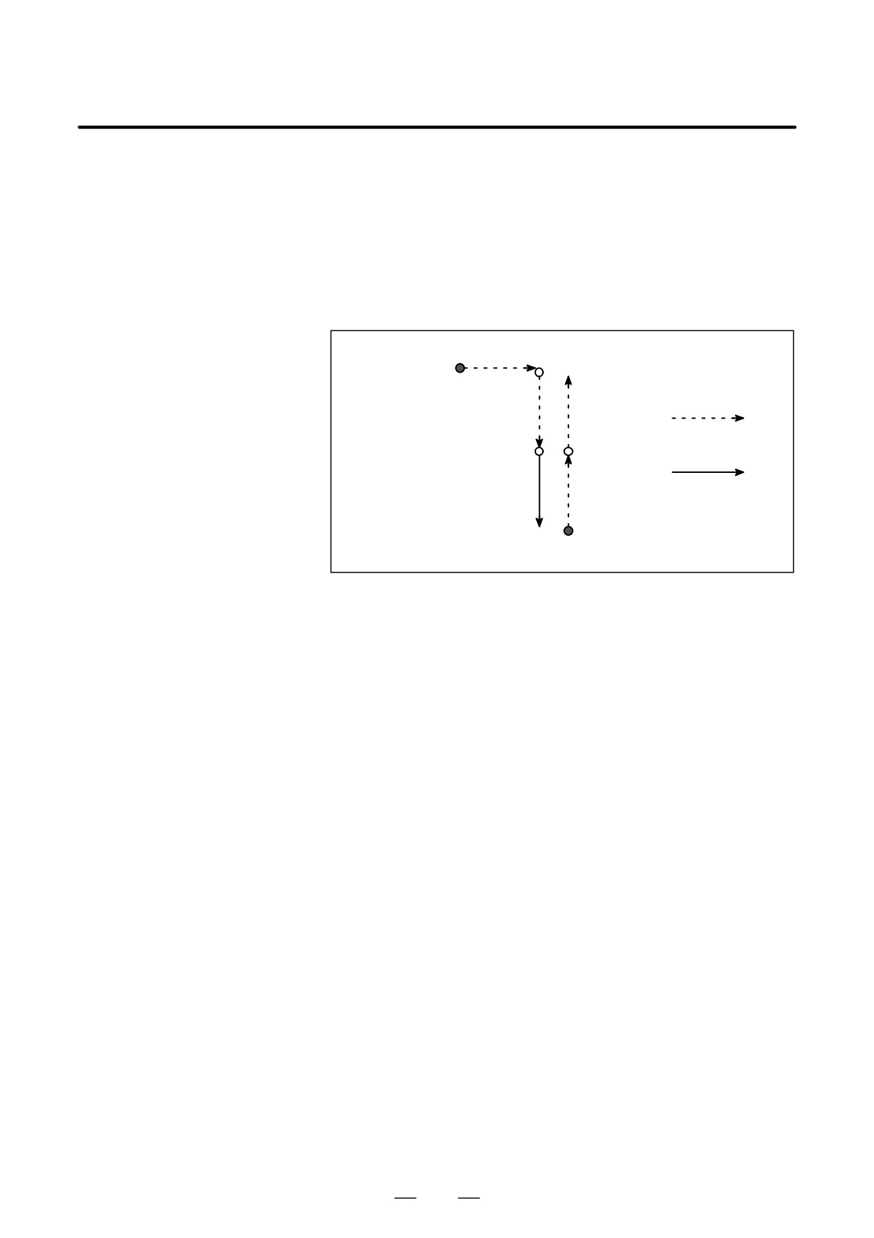
In a canned cycle, the single block stop points are the end of
,
, and
canned cycle
shown below. When the single block stop is made after the point
or
, the feed hold LED lights.
Rapid traverse
Feed
Fig. 5.5 (b) Single block during canned cycle
D Subprogram call and
Single block stop is not performed in a block containing M98P_;. M99;
single block
or G65.
However, single block stop is even performed in a block with M98P_ or
M99 command, if the block contains an address other than O, N, P, L.
851
6. SAFETY FUNCTIONS
OPERATION
B-63534EN/02
SAFETY FUNCTIONS
6
To immediately stop the machine for safety, press the Emergency stop
button. To prevent the tool from exceeding the stroke ends, Overtravel
check and Stroke check are available. This chapter describes emergency
stop., overtravel check, and stroke check.
852

B-63534EN/02
OPERATION
6. SAFETY FUNCTIONS
If you press Emergency Stop button on the machine operator’s panel, the
6.1
machine movement stops in a moment.
EMERGENCY STOP
Red
EMERGENCY STOP
Fig. 6.1 Emergency stop
This button is locked when it is pressed. Although it varies with the
machine tool builder, the button can usually be unlocked by twisting it.
Explanation
EMERGENCY STOP interrupts the current to the motor.
Causes of trouble must be removed before the button is released.
853
6. SAFETY FUNCTIONS
OPERATION
B-63534EN/02
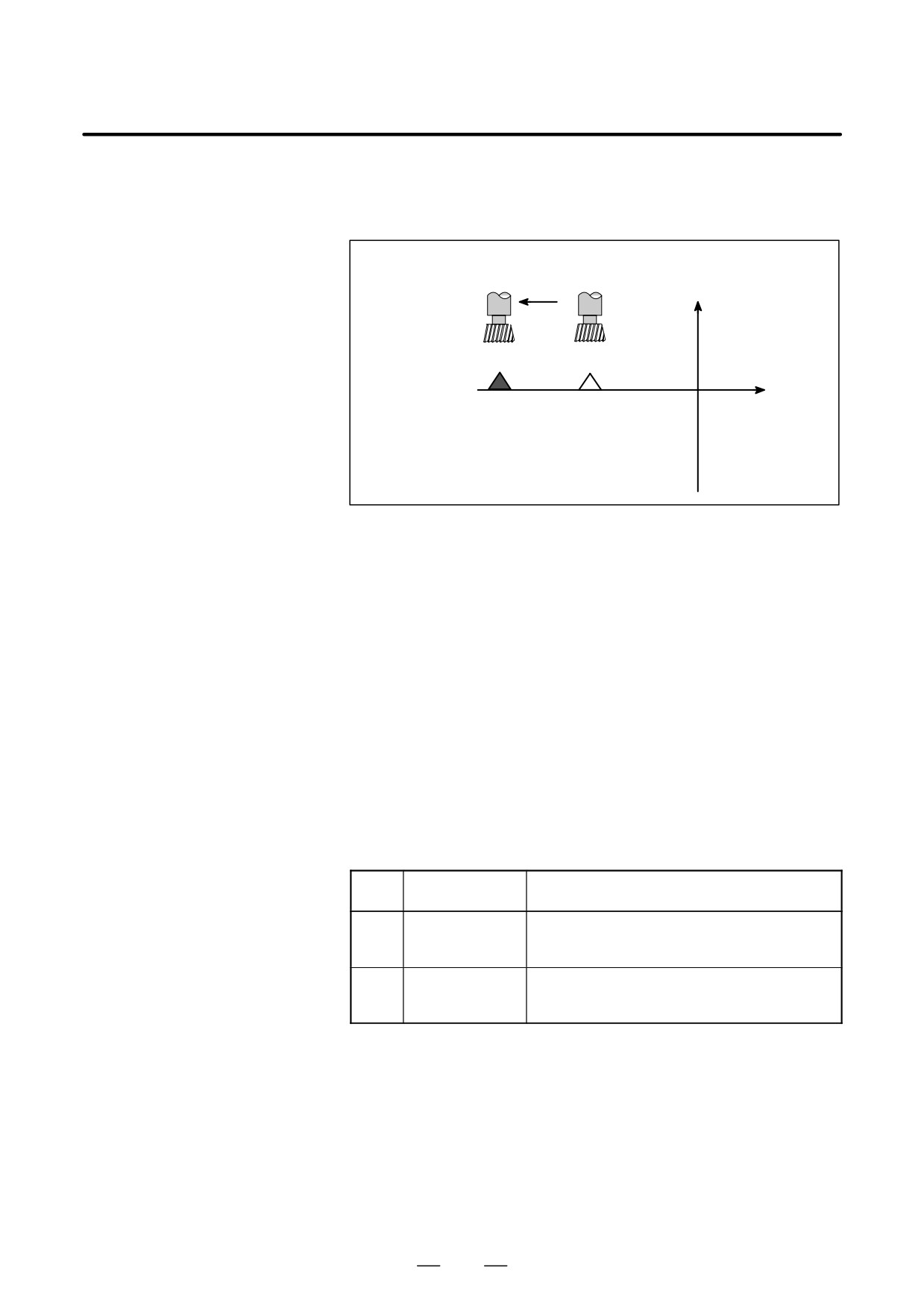
When the tool tries to move beyond the stroke end set by the machine tool
6.2
limit switch, the tool decelerates and stops because of working the limit
OVERTRAVEL
switch and an OVER TRAVEL is displayed.
Deceleration and stop
Y
X
Stroke end
Limit switch
Fig. 6.2 Overtravel
Explanation
D Overtravel during
When the tool touches a limit switch along an axis during automatic
automatic operation
operation, the tool is decelerated and stopped along all axes and an
overtravel alarm is displayed.
D Overtravel during
In manual operation, the tool is decelerated and stopped only along the
manual operation
axis for which the tool has touched a limit switch. The tool still moves
along the other axes.
Press the reset button to reset the alarm after moving the tool to the safety
D Releasing overtravel
direction by manual operation. For details on operation, refer to the
operator’s manual of the machine tool builder.
Alarm
Alarm
Message
Description
No.
The tool has exceeded the hardware-specified
506
Overtravel: +n
overtravel limit along the positive nth axis
(n:
1 to 8).
The tool has exceeded the hardware-specified
507
Overtravel: -n
overtravel limit along the negative nth axis
(n:
1 to 8).
854
B-63534EN/02
OPERATION
6. SAFETY FUNCTIONS
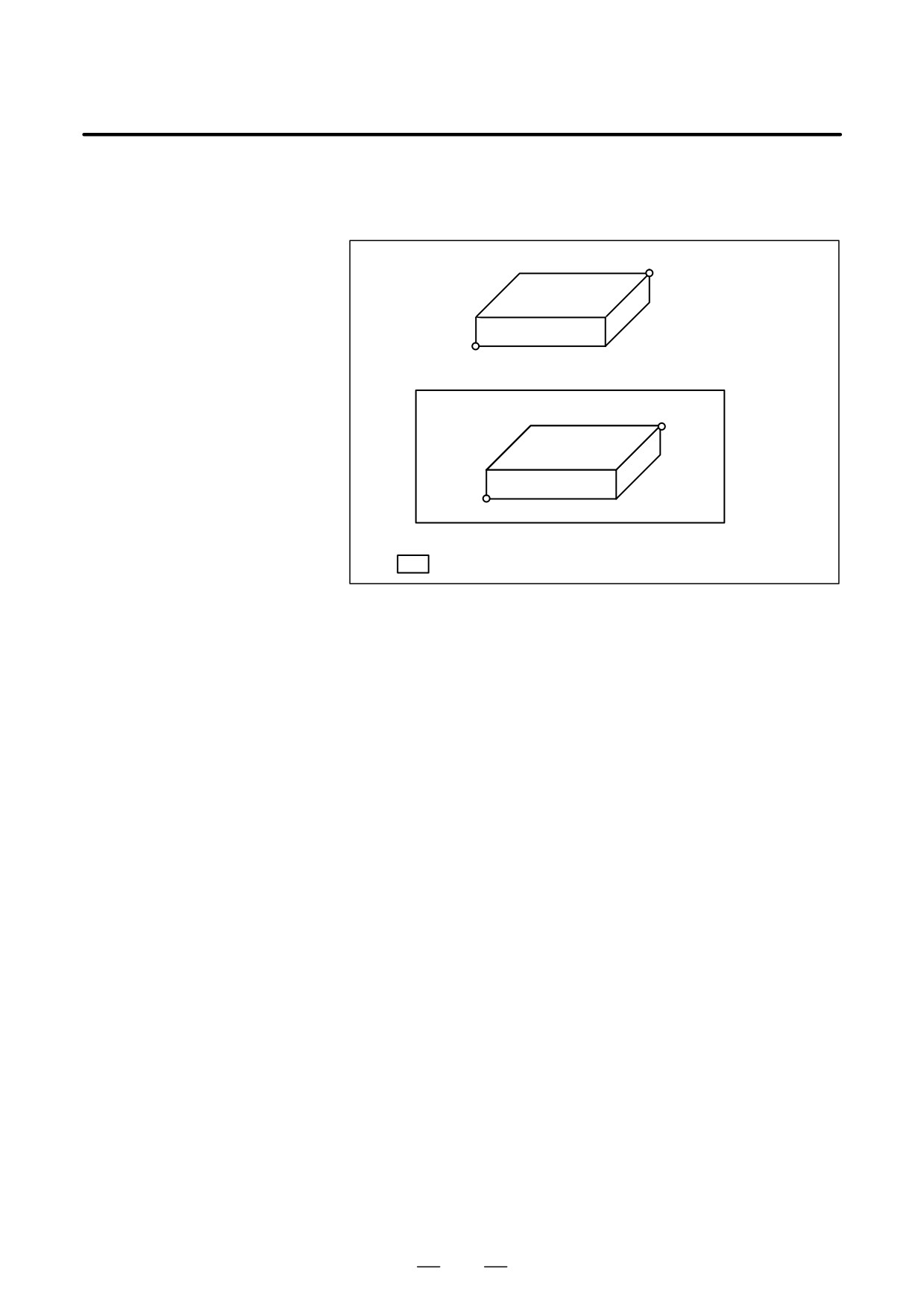
Three areas which the tool cannot enter can be specified with stored stroke
6.3
check 1, stored stroke check 2, and stored stroke check 3.
STORED STROKE
CHECK
(X,Y,Z)
ÇÇÇÇÇÇÇ
ÇÇÇÇÇÇÇÇ
ÇÇÇÇÇÇÇÇ
(I,J,KÇ
ÇÇÇÇÇÇ
(1)Forbidden area is inside.
ÇÇÇÇÇÇÇÇÇÇÇ(X,Y,Z)Ç
ÇÇÇÇÇÇÇÇÇÇÇÇÇÇ
ÇÇÇÇÇÇÇÇÇÇÇÇÇÇ
ÇÇÇÇÇÇÇÇÇÇÇÇÇÇ
,J,K)
ÇÇÇÇÇÇÇ
ÇÇÇÇÇÇÇÇÇÇÇÇÇÇ
(2)Forbidden area is outside
ÇÇ : Forbidden area for the tool
Fig. 6.3 (a) Stroke check
When the tool exceeds a stored stroke limit, an alarm is displayed and the
tool is decelerated and stopped.
When the tool enters a forbidden area and an alarm is generated, the tool
can be moved in the reverse direction from which the tool came.
Explanation
D Stored stroke check 1
Parameters (Nos. 1320, 1321 or Nos. 1326, 1327) set boundary. Outside
the area of the set limits is a forbidden area. The machine tool builder
usually sets this area as the maximum stroke.
D Stored stroke check 2
Parameters (Nos. 1322, 1323) or commands set these boundaries. Inside
(G22, G23)
or outside the area of the limit can be set as the forbidden area. Parameter
OUT (No. 1300#0) selects either inside or outside as the forbidden area.
In case of program command a G22 command forbids the tool to enter the
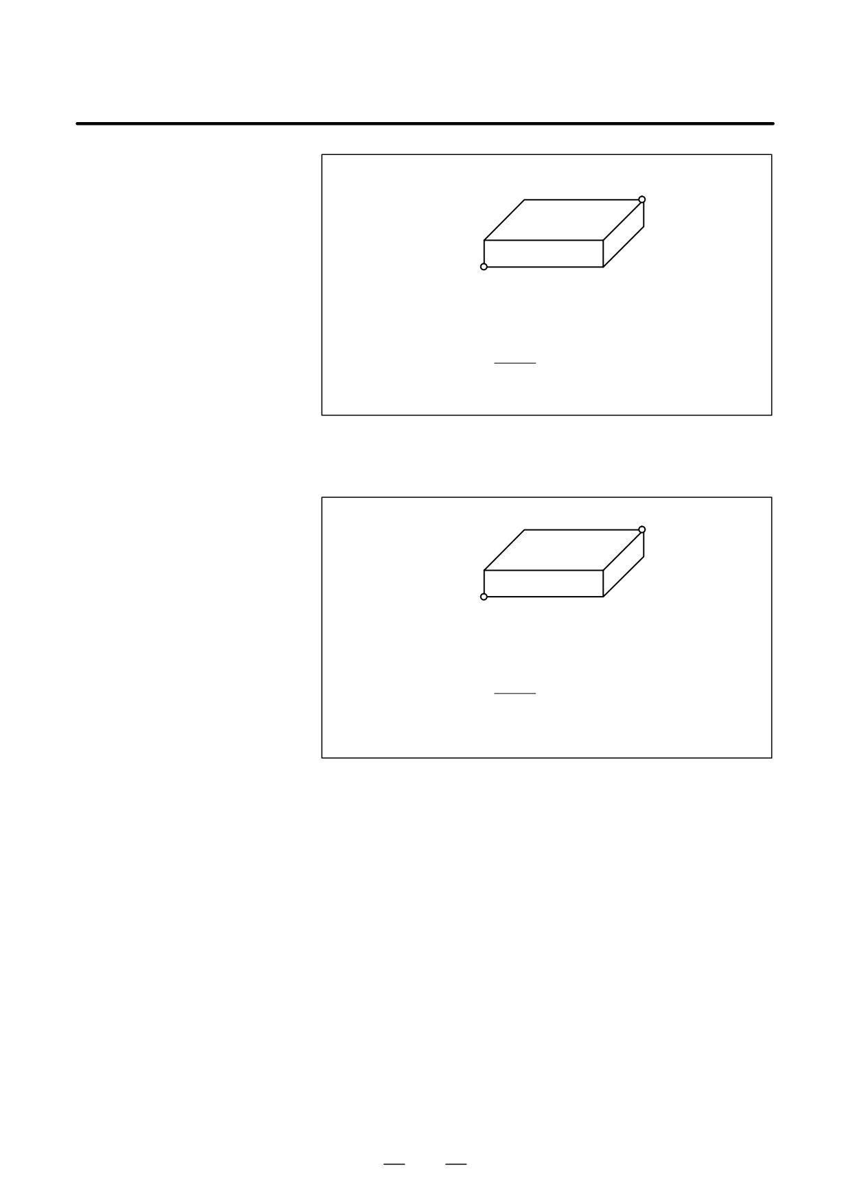
forbidden area, and a G23 command permits the tool to enter the
forbidden area. Each of G22; and G23; should be commanded
independently of another commands in a block.
The command below creates or changes the forbidden area:
855
6. SAFETY FUNCTIONS
OPERATION
B-63534EN/02
G 22X_Y_Z_I_J_K_;
(X,Y,Z)
ÇÇÇÇÇÇÇÇ
ÇÇÇÇÇÇÇÇ
ÇÇÇÇÇÇÇ
(I,J,K)
ÇÇÇÇÇÇ
X>I, Y>J, Z>K
X-I >ζ (In least command increment)
Y-J >ζ (In least command increment)
Z-K >ζ ((In least command increment)
F
ζ (mm)=
7500
F=Rapid traverse speed (mm/min)
Fig. 6.3 (b) Creating or changing the forbidden area using a program
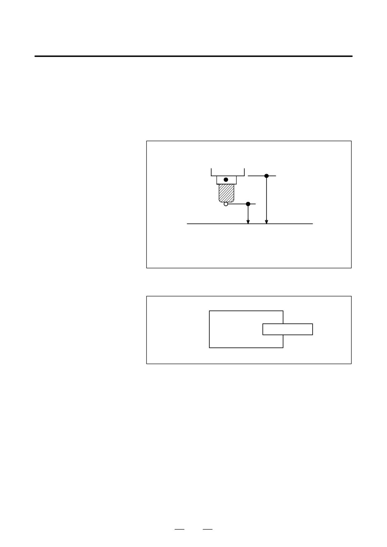
When setting the area by parameters, points A and B in the figure below
must be set.
A (X,Y,Z)
ÇÇÇÇÇÇÇ
ÇÇÇÇÇÇÇÇ
ÇÇÇÇÇÇÇ
B (I,J,K)
ÇÇÇÇÇÇ
X>I, Y>J, Z>K
X-I >ζ (In least command increment)
Y-J >ζ (In least command increment)
Z-K >ζ ((In least command increment)
F
ζ (mm)=
7500
F=Rapid traverse speed (mm/min)
Fig. 6.3 (c) Creating or changing the forbidden area using a parameters
In stored stroke check 2, even if you mistake the order of the coordinate
value of the two points, a rectangular, with the two points being the
apexes, will be set as the area.
When you set the forbidden area through parameters (Nos. 1322, 1323),
the data should be specified by the distance from the machine coordinate
system in the least command increment. (Output increment)
If it is set by a G22 command, specify the data by the distance from the
machine coordinate system in the least input increment (Input increment.)
The programmed data are then converted into the numerical values in the
least command increment, and the values are set as the parameters.
D Stored stroke check 3
Set the boundary with parameters No. 1324 and 1325. The area inside the
boundary becomes the forbidden area.
856
B-63534EN/02
OPERATION
6. SAFETY FUNCTIONS
D Checkpoint for the
Confirm the checking position (the top of the tool or the tool chuck) before
forbidden area
programming the forbidden area.
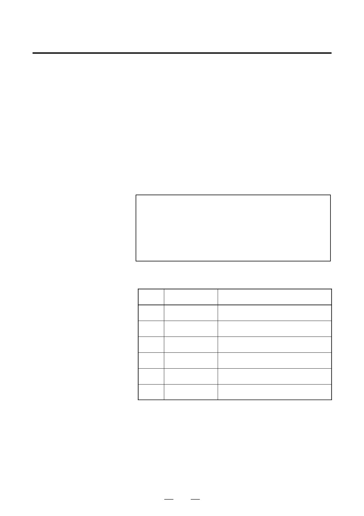
If point A (The top of the tool) is checked in Fig. 6.3 (d) , the distance “a”
should be set as the data for the stored stroke limit function. If point B
(The tool chuck) is checked, the distance “b” must be set. When checking
the tool tip (like point A), and if the tool length varies for each tool, setting
the forbidden area for the longest tool requires no re-setting and results
in safe operation.
B
The position of the
tool after reference
position return
b
A
a
Area boundary
ÇÇÇÇÇÇÇÇÇÇÇÇÇÇ
ÇÇÇÇÇÇÇÇÇÇÇÇÇÇ
Fig. 6.3 (d) Setting the forbidden area
D Forbidden area
Area can be set in piles.
over lapping
ÇÇÇÇÇÇÇÇÇÇ
Ç
ÇÇ
Ç
ÇÇÇÇÇÇ
Ç
ÇÇÇÇÇÇ
Ç
ÇÇ
ÇÇÇÇÇÇÇÇÇÇ
Fig. 6.3 (e) Setting the forbidden area over lapping
Unnecessary limits should be set beyond the machine stroke.
D Overrun amount of
If the maximum rapid traverse rate is F (mm/min), the maximum overrun
stored stroke limit
amount, L (mm), of the stored stroke limit is obtained from the following
expression:
L (mm) = F/7500
The tool enters the specified inhibited area by up to L (mm). Bit 7 (BFA)
of parameter No. 1300 can be used to stop the tool when it reaches a point
L mm short of the specified area. In this case, the tool will not enter the
inhibited area.
D Effective time for a
Each limit becomes effective after the power is turned on and manual
forbidden area
reference position return or automatic reference position return by G28
has been performed.
After the power is turned on, if the reference position is in the forbidden
area of each limit, an alarm is generated immediately. (Only in G22 mode
for stored stroke limit 2).
857
6. SAFETY FUNCTIONS
OPERATION
B-63534EN/02
D Releasing the alarms
If the enters a forbidden area and an alarm is generated, the tool can be
moved only in the backward direction. To cancel the alarm, move the tool
backward until it is outside the forbidden area and reset the system. When
the alarm is canceled, the tool can be moved both backward and forward.
D Change from G23 to
When G23 is switched to G22 in the forbidden area, the following results.
G22 in a forbidden area
(1) When the forbidden area is inside, an alarm is informed in the next
move.
(2) When the forbidden area is outside, an alarm is informed immediately.
D Timing for displaying
Parameter BFA (bit 7 of No. 1300) selects whether an alarm is displayed
an alarm
immediately before the tool enters the forbidden area or immediately after
the tool has entered the forbidden area.
D Setting a forbidden area
For two-path control, set a fobidden area for each path.
for two-path control
NOTE
In setting a forbidden area, if the two points to be set are the
same, the area is as follows:
(1) When the forbidden area is stored stroke check 1, all areas
are forbidden areas.
(2) When the forbidden area is stored stroke check 2 or stored
stroke check 3, all areas are movable areas.
Alarms
Alarm
Message
Contents
Number
500
OVER TRAVEL: +n
Exceeded the n-th axis (1-8) + side stored
stroke limit I.
501
OVER TRAVEL: -n
Exceeded the n-th axis (1-8)
* side
stored stroke limit I.
502
OVER TRAVEL: +n
Exceeded the n-th axis (1-8) + side stored
stroke limit II.
503
OVER TRAVEL: -n
Exceeded the n-th axis (1-8)
* side
stored stroke limit II.
504
OVER TRAVEL: +n
Exceeded the n-th axis (1-8) + side stored
stroke limit III.
505
OVER TRAVEL: -n
Exceeded the n-th axis (1-8)
* side
stored stroke limit III.
858
B-63534EN/02
OPERATION
6. SAFETY FUNCTIONS
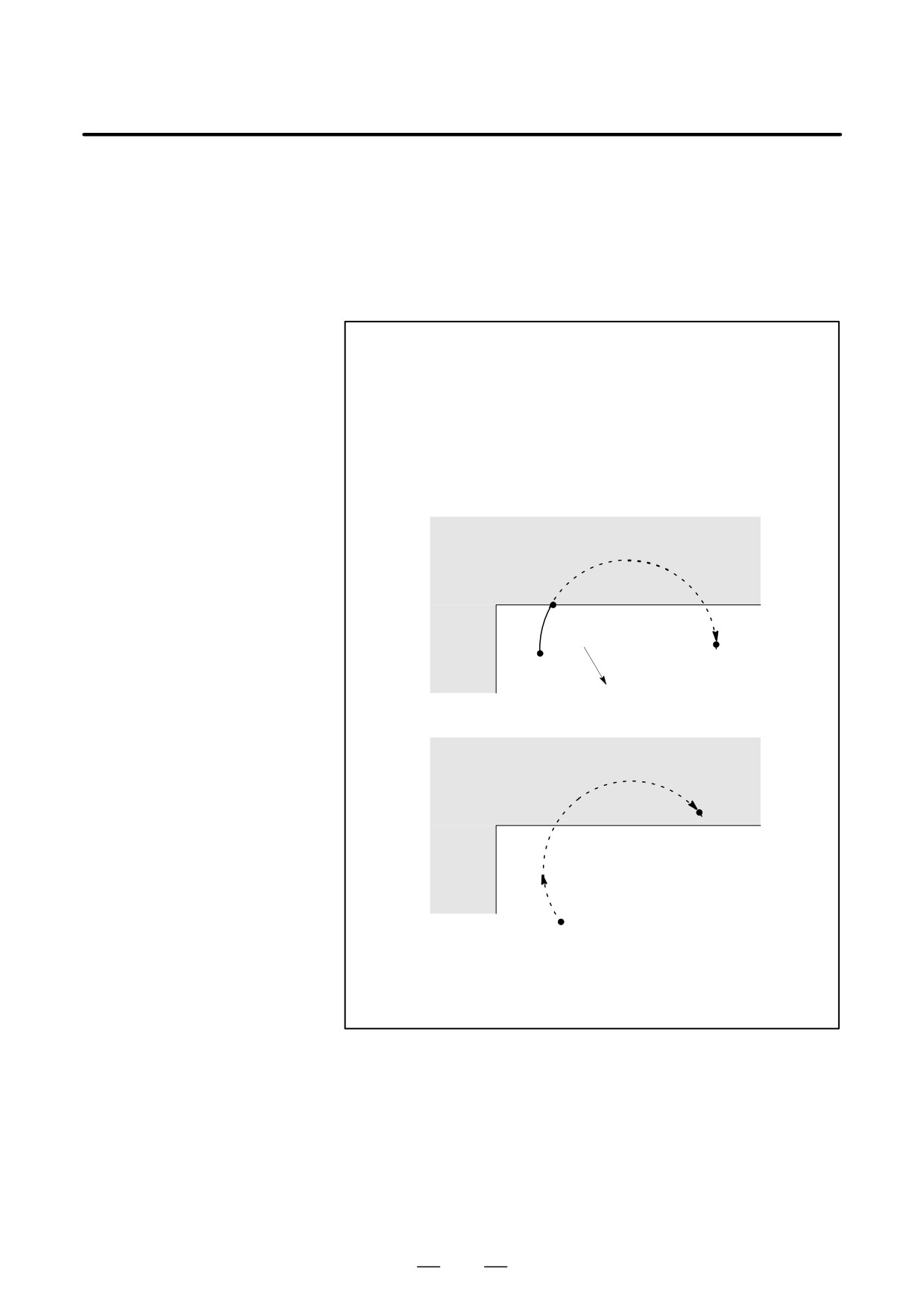
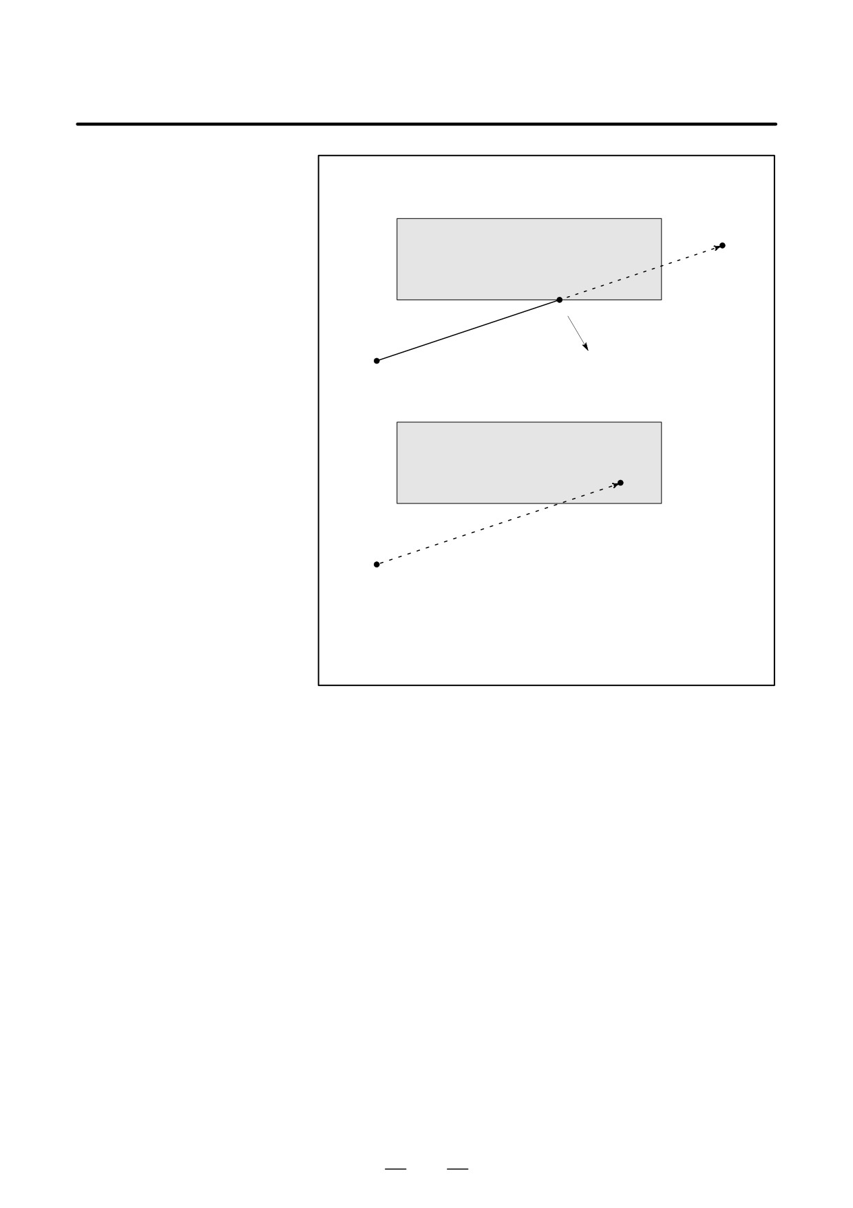
During automatic operation, before the movement specified by a given
6.4
block is started, whether the tool enters the inhibited area defined by
STROKE LIMIT
stored stroke limit 1, 2, or 3 is checked by determining the position of the
CHECK PRIOR TO
end point from the current position of the machine and a specified amount
of travel. If the tool is found to enter the inhibited area defined by a stored
PERFORMING
stroke limit, the tool is stopped immediately upon the start of movement
MOVEMENT
for that block, and an alarm is displayed.
WARNING
Whether the coordinates of the end point, reached as a
result of traversing the distance specified in each block, are
in a inhibited area is checked. In this case, the path followed
by a move command is not checked. However, if the tool
enters the inhibited area defined by stored stroke limit 1, 2,
or 3, an alarm is issued.
(See the examples below.)
Example 1)
Inhibited area defined by
stored stroke limit 1 or 2
a
End point
Start point
The tool is stopped at point a according
to stored stroke limit 1 or 2.
Inhibited area defined by
stored stroke limit 1 or 2
End point
Immediately upon movement commencing
from the start point, the tool is stopped to
enable a stroke limit check to be performed
before movement.
859
6. SAFETY FUNCTIONS
OPERATION
B-63534EN/02
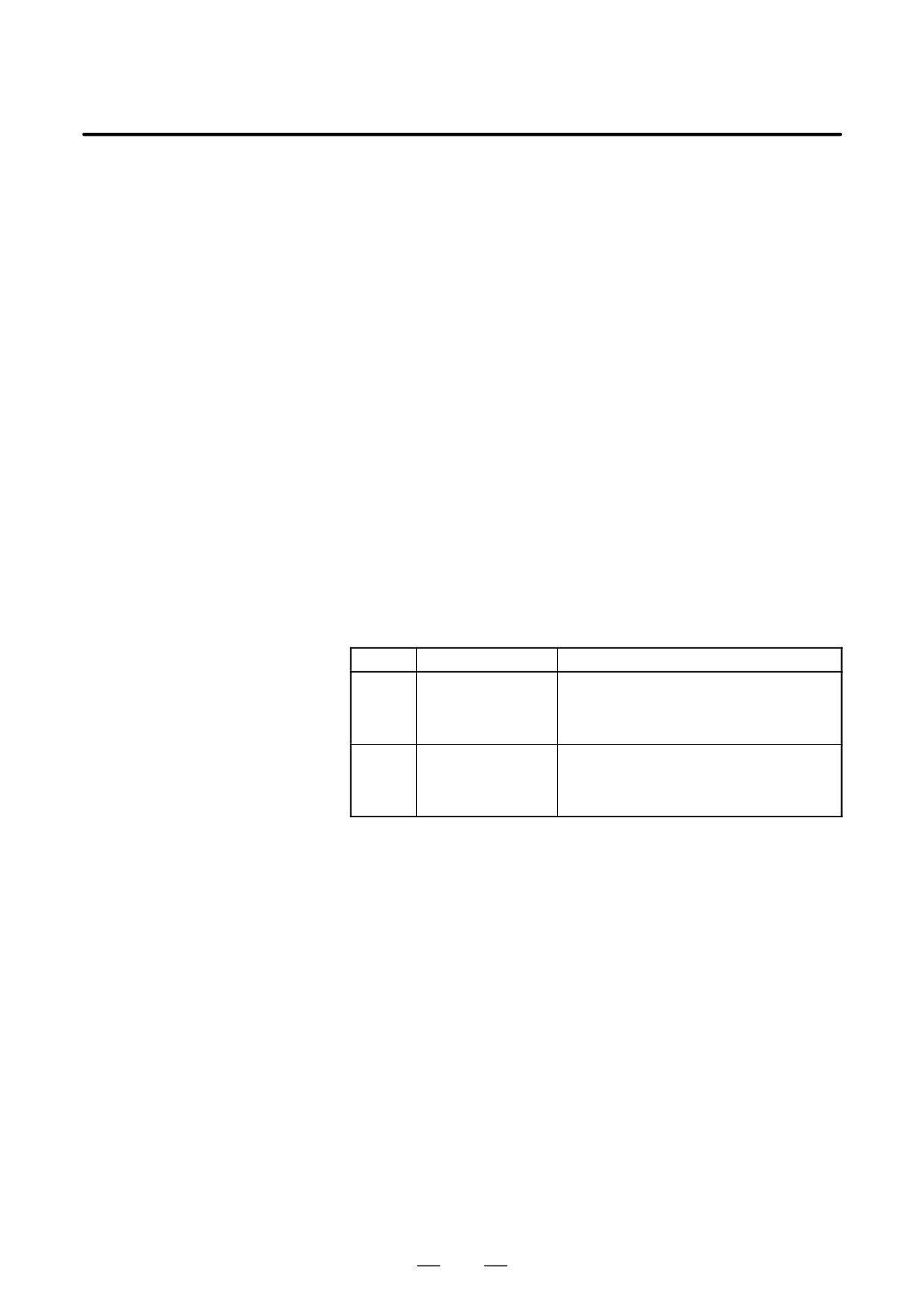
Example 2)
End point
Inhibited area defined by
stored stroke limit 1 or 2
a
The tool is stopped at point a according
Start point
to stored stroke limit 1 or 2.
Inhibited area defined by
stored stroke limit 1 or 2
End point
Immediately upon movement commencing
from the start point, the tool is stopped to
enable a stroke limit check to be performed
before movement.
Explanations
When a stroke limit check prior to movement is performed, whether to
check the movement performed by a G31 (skip) block and G37 (automatic
tool length measurement) block can be determined using NPC (bit 2 of
parameter No. 1301).
Limitations
D Machine lock
If machine lock is applied at the start of movement, no stroke limit check
made before movement is performed.
D G23
When stored stroke limit 2 is disabled (G23 mode), no check is made to
determine whether the tool enters the inhibited area defined by stored
stroke limit 2.
D Program restart
When a program is restarted, an alarm is issued if the restart position is
within a inhibited area.
D Manual intervention
When the execution of a block is restarted after manual intervention
following a feed hold
following a feed hold stop, no alarm is issued even if the end point
stop
following a manual intervention is within a inhibited area.
D A block consisting of
If a block consisting of multiple operations (such as a canned cycle and
multiple operations
exponential interpolation) is executed, an alarm is issued at the start point
of any operation whose end point falls within a inhibited area.
860
B-63534EN/02
OPERATION
6. SAFETY FUNCTIONS
D Cyrindrical interpolation
In cylindrical interpolation mode, no check is made.
mode
D Polar coordinate
In polar coordinate interpolation mode, no check is made.
interpolation mode
D Angular axis control
When the angulalr axis control option is selected, no check is made.
D Simple synchronous
In simple synchronous control, only the master axis is checked; no slave
control
axes are checked.
D Three-dimensional
In three-dimensional coordinate conversion mode, no check is made.
coordinate conversion
D Drawing
No check is performed while drawing is being performed as part of
dynamic graphic display
(only drawing
(no machining) is being
performed).
D PMC axis control
No check is made for a movement based on PMC axis control.
D High-speed
No check is made for a movement based on high-speed, high-precision
high-precision contour
contour control (HPCC).
control (HPCC)
Alarm
Number
Message
Contents
The pre-movement stroke limit check re-
veals that the block end point enters the
510
OVER TRAVEL : +n
prohibited area for the positive stroke limit
along the n axis. Correct the program.
The pre-movement stroke limit check re-
veals that the block end point enters the
511
OVER TRAVEL : -n
prohibited area for the negative stroke limit
along the n axis. Correct the program.
861
7. ALARM AND SELF-DIAGNOSIS
FUNCTIONS
OPERATION
B-63534EN/02
ALARM AND SELF-DIAGNOSIS FUNCTIONS
7
When an alarm occurs, the corresponding alarm screen appears to indicate
the cause of the alarm. The causes of alarms are classified by error codes.
Up to 25 previous alarms can be stored and displayed on the screen (alarm
history display).
The system may sometimes seem to be at a halt, although no alarm is
displayed. In this case, the system may be performing some processing.
The state of the system can be checked using the self-diagnostic function.
862
7. ALARM AND SELF-DIAGNOSIS
B-63534EN/02
OPERATION
FUNCTIONS
7.1
ALARM DISPLAY
Explanations
D Alarm screen
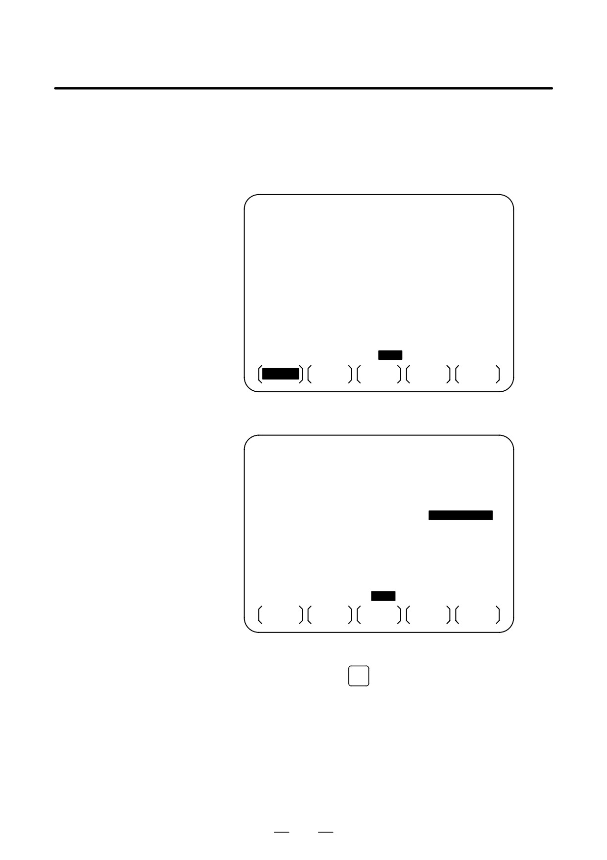
When an alarm occurs, the alarm screen appears.
ALARM MESSAGE
0000
00000
100
PARAMETER WRITE ENABLE
510
OVER TR1AVEL :+X
520
OVER TRAVEL
:+2
530
OVER TRAVEL
:+3
S
0 T0000
MDI
ALM
18 : 52 : 05
****
***
***
ARALM
MSG
HISTRY
D Another method for
In some cases, the alarm screen does not appear, but an ALM is displayed
alarm displays
at the bottom of the screen.
PARAMETER (RS232C INTERFACE)
O1000 N00010
0100 ENS
NCR CTV
0
0
0
0
0
0
0
0
0101 NFD
XIK
ASI SB2
0
0
0
0
0
0
0
1
0102 DEVICE NUM. (CH0)
2
0103 BAUDRATE (CH0)
10
0111
NFD
ASI SB2
0
0
0
0
0
0
0
0
0112 DEVICE NUM. (CH1)
0
0113 BAUDRATE (CH1)
0
>_
S
0 T0000
MEM * * * *
* * *
* * *
ALM
08 : 41 : 27
NO.SRH
ON:1
OFF:0
+INPUT
INPUT
In this case, display the alarm screen as follows:
1. Press the function key
MESSAGE
2. Press the chapter selection soft key [ALARM].
863
7. ALARM AND SELF-DIAGNOSIS
FUNCTIONS
OPERATION
B-63534EN/02
D Reset of the alarm
Error codes and messages indicate the cause of an alarm. To recover from
an alarm, eliminate the cause and press the reset key.
D Error codes
The error codes are classified as follows:
No. 000 to 255
: P/S alarm (Program errors) (*)
No. 300 to 349
: Absolute pulse coder (APC) alarms
No. 350 and 399
: Serial pulse coder (SPC) alarms
No. 400 to 499
: Servo alarms
No. 500 to 599
: Overtravel alarms
No. 700 to 739
: Overheat alarms
No. 740 to 748
: Rigid tapping alarms
No. 749 to 799
: Spindle alarms
No. 900 to 999
: System alarms
No. 5000 to
: P/S alarm (Program errors)
* For an alarm (No. 000 to 255) that occurs in association with
background operation, the indication “xxxBP/S alarm” is provided
(where xxx is an alarm number). Only a BP/S alarm is provided for
No. 140.
See the error code list in the Appendix G for details of the error codes.
864
7. ALARM AND SELF-DIAGNOSIS
B-63534EN/02
OPERATION
FUNCTIONS
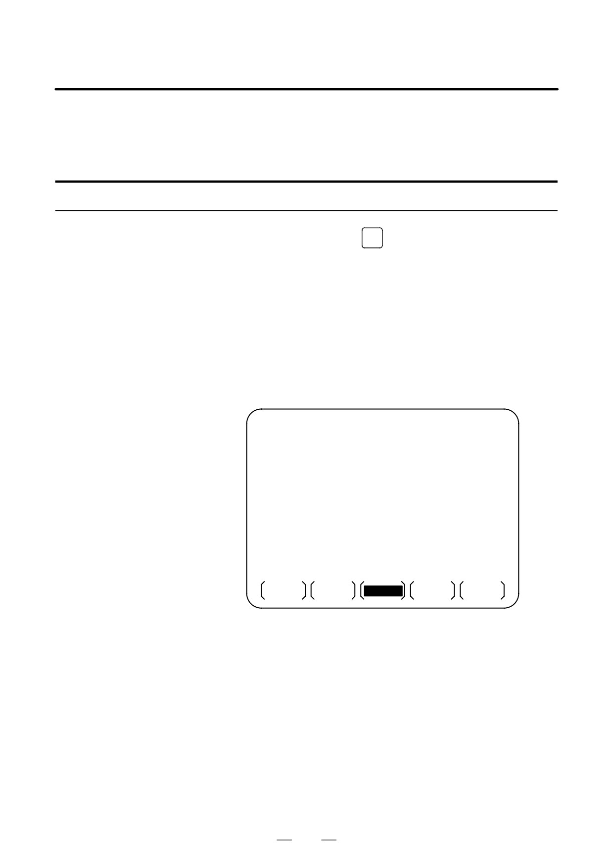
Up to 25 of the most recent CNC alarms are stored and displayed on the
7.2
screen.
ALARM HISTORY
Display the alarm history as follows:
DISPLAY
Procedure for Alarm History Display
Procedure
MESSAGE
1
Press the function key
2
Press the chapter selection soft key [HISTRY].
The alarm history appears.
The following information items are displayed.
(1)The date the alarm was issued
(2)Alarm No.
(3)Alarm message (some contains no message)
(4)Page No.
3
Change the page by the 1-page change key.
4
To delete the recorded information, press the softkey [(OPRT)] then
the [DELETE] key.
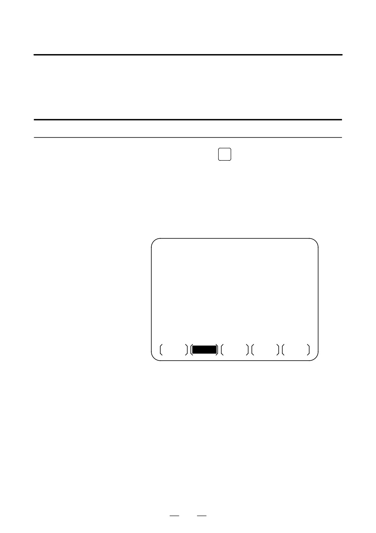
ALARM HISTORY
O0100 N00001
PAGE=1
(1)01.02.14 16:43:48
(4)
(2)010 (3)MPROPER G-CODE
01.02.13 8:22:21
506 OVER TRAVEL : +1
01.02.12 20:15:43
417 SERVO ALARM : X AXIS DGTL PARAM
MEM * * * *
***
***
19 : 47 : 45
ALARM
MSG
HISTRY
(OPRT)
865
7. ALARM AND SELF-DIAGNOSIS
FUNCTIONS
OPERATION
B-63534EN/02
The system may sometimes seem to be at a halt, although no alarm has
7.3
occurred. In this case, the system may be performing some processing.
CHECKING BY
The state of the system can be checked by displaying the self-diagnostic
SELF-DIAGNOSTIC
screen.
SCREEN
Procedure for Diagnois
Procedure
1
Press the function key
SYSTEM
2
Press the chapter select key [DGNOS].
3
The diagnostic screen has more than 1 pages. Select the screen by the
following operation.
(1) Change the page by the 1-page change key.
(2) Method by soft key
- Key input the number of the diagnostic data to be displayed.
- Press [N SRCH].
DIAGNOSTIC (GENERAL)
O0000 N0000
000
WAITING FOR FIN SIGNAL
:0
001
MOTION
:0
002
DWELL
:0
003
IN-POSITION CHECK
:0
004
FEEDRATE OVERRIDE 0%
:0
005
INTERLOCK/START-LOCK
:0
006
SPINDLE SPEED ARRIVAL CHECK
:0
>_
EDIT
****
***
***
14 : 51 : 55
PARAM
DGNOS
PMC
SYSTEM
(OPRT)
Explanations
D Self diagnostic screen at
For the two-path control, the diagnostic screen for the path selected with
2-path control
the path selection switch is displayed. When displaying the diagnostic
screen for the other tool post, specify the path with the tool post selection
switch.
866
7. ALARM AND SELF-DIAGNOSIS
B-63534EN/02
OPERATION
FUNCTIONS
Explanations
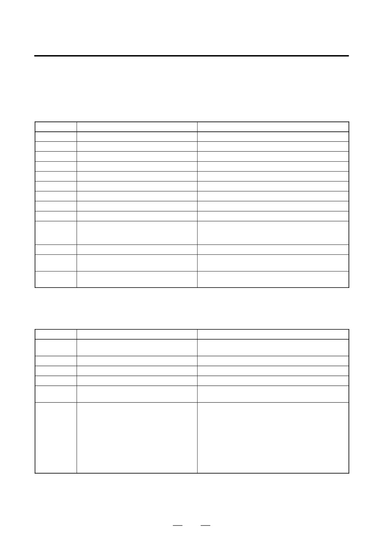
Diagnostic numbers 000 to 015 indicate states when a command is being
specified but appears as if it were not being executed. The table below
lists the internal states when 1 is displayed at the right end of each line on
the screen.
Table 7.3 (a) Alarm displays when a command is specified but appears as if it were not being executed
No.
Display
Internal status when 1 is displayed
000
WAITING FOR FIN SIGNAL
M, S. T function being executed
001
MOTION
Move command in automatic operation being executed
002
DWELL
Dwell being executed
003
IN-POSITION CHECK
In-position check being executed
004
FEEDRATE OVERRIDE 0%
Cutting feed override 0%
005
INTERLOCK/START-LOCK
Interlock ON
006
SPINDLE SPEED ARRIVAL CHECK
Waiting for spindle speed arrival signal to turn on
010
PUNCHING
Data being output via reader puncher interface
011
READING
Data being input via reader puncher interface
012
WAITING FOR (UN) CLAMP
Waiting for index table clamp/unclamp before B axis in-
dex table indexing start/after B axis index table indexing
end to complete
013
JOG FEEDRATE OVERRIDE 0%
Jog override 0%
014
WAITING FOR RESET.ESP.RRW.OFF
Emergency stop, external reset, reset & rewind, or MDI
panel reset key on
015
EXTERNAL PROGRAM
External program number searching
NUMBER SEARCH
Diagnostic numbers 020 to 025 indicate states when an automatic
operation is stopped or paused.
Table 7.3 (b) Alarm displays when an automatic operation is stopped or paused.
No.
Display
Internal status when 1 is displayed
020
CUT SPEED UP/DOWN
Set when emergency stop turns on or when servo alarm
occurs
021
RESET BUTTON ON
Set when reset key turns on
022
RESET AND REWIND ON
Reset and rewind turned on
023
EMERGENCY STOP ON
Set when emergency stop turns on
024
RESET ON
Set when external reset, emergency stop, reset, or reset
& rewind key turns on
025
STOP MOTION OR DWELL
A flag which stops pulse distribution. It is set in the fol-
lowing cases.
(1) External reset turned on.
(2) Reset & rewind turned on.
(3) Emergency stop turned on.
(4) Feed hold turned on.
(5) The MDI panel reset key turned on.
(6) Switched to the manual mode(JOG/HANDLE/INC).
(7) Other alarm occurred.
(There is also alarm which is not set.)
867
7.
ALARM AND SELF-DIAGNOSIS
FUNCTIONS
OPERATION
B-63534EN/02
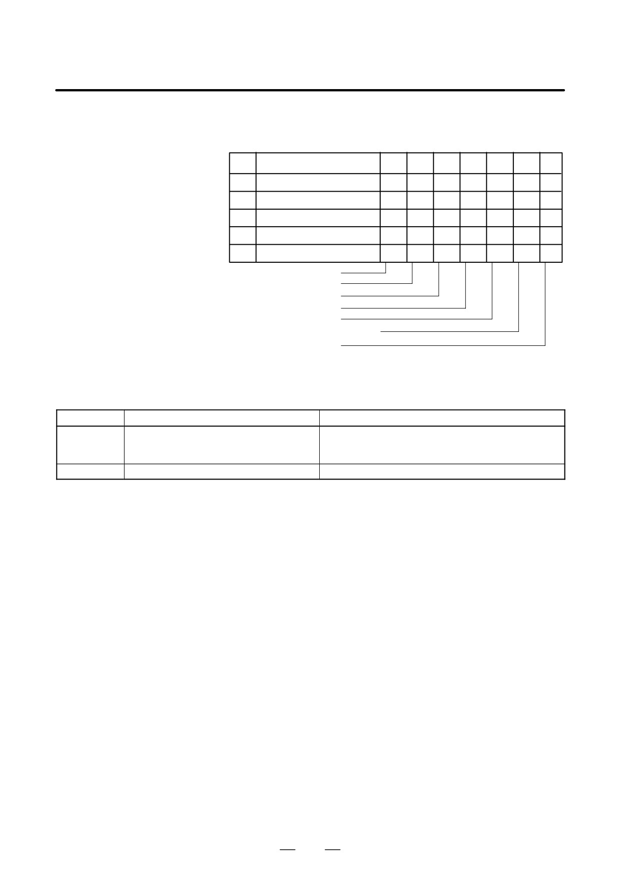
The table below shows the signals and states which are enabled when each
diagnostic data item is 1. Each combination of the values of the diagnostic
data indicates a unique state.
020
CUT SPEED UP/DOWN
1
0
0
0
1
0
0
021
RESET BUTTON ON
0
0
1
0
0
0
0
022
RESET AND REWIND ON
0
0
0
0
0
0
0
023
EMERGENCY STOP ON
1
0
0
0
0
0
0
024
RESET ON
1
1
1
1
0
0
0
025
STOP MOTION OR DWELL
1
1
1
1
1
1
0
Emergency stop signal input
External reset signal input
MDI reset button turned on
Reset & rewind input
Servo alarm generation
Changed to another mode or feed hold
Single block stop
Diagnostic numbers 030 and 031 indicate TH alarm states.
Diagnostic numbers 030 and 031 indicate TH alarm states.
No.
Display
Meaning of data
030
CHARACTER NUMBER TH DATA
The position of the character which caused TH alarm is
displayed by the number of characters from the begin-
ning of the block at TH alarm
031
TH DATA
Read code of character which caused TH alarm
868
B-63534EN/02
OPERATION
8. DATA INPUT/OUTPUT
DATA INPUT/OUTPUT
8
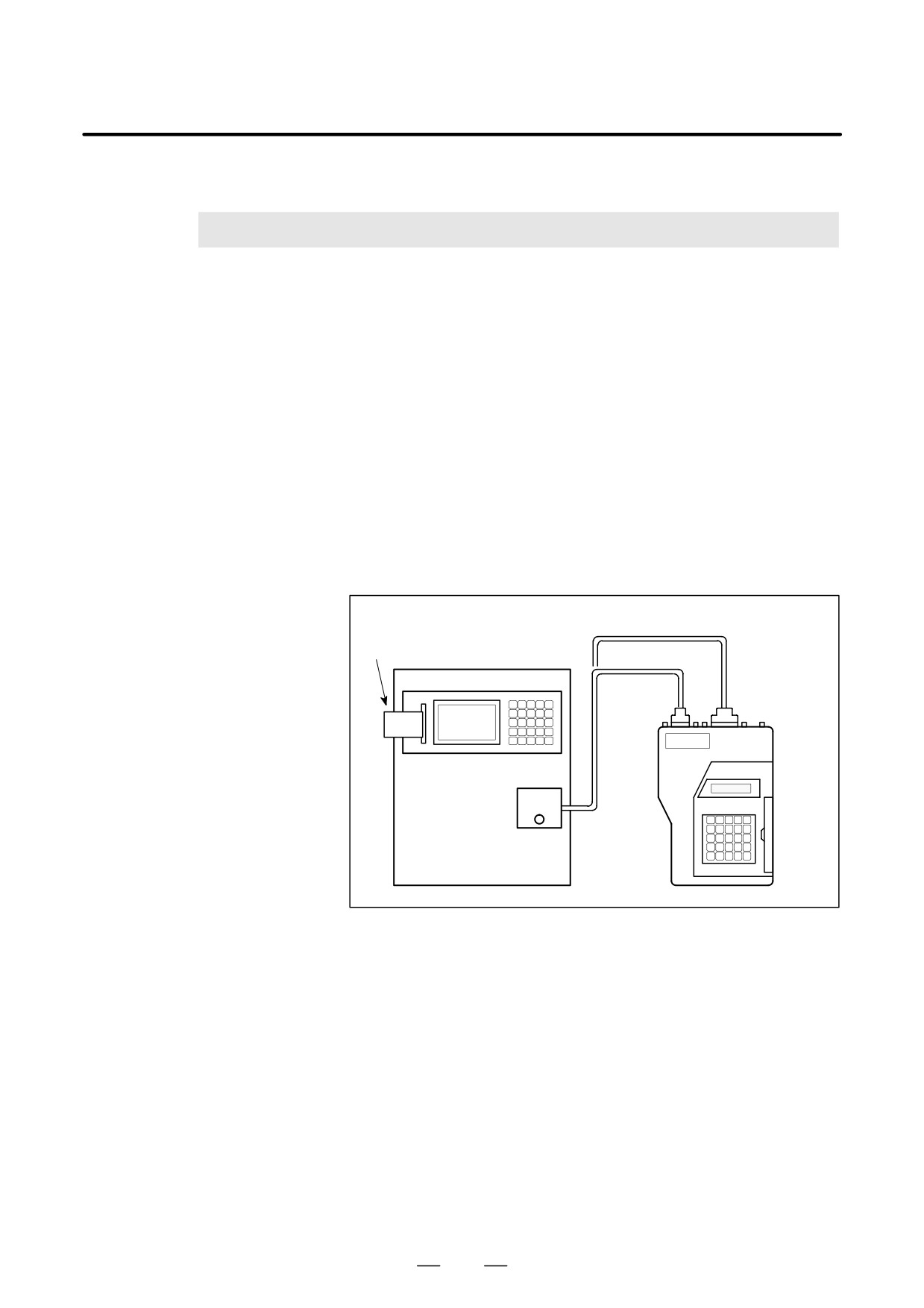
NC data is transferred between the NC and external input/output devices
such as the Handy File.
The memory card interface located to the left of the display can be used
to read information on a memory card in the CNC or write it to the card.
The following types of data can be entered and output :
1.Program
2.Offset data
3.Parameter
4.Pitch error compensation data
5.Custom macro common variable
Before an input/output device can be used, the input/output related
parameters must be set.
For how to set parameters, see III-2 “OPERATIONAL DEVICES”.
RS-422
interface
Memory card
RS-232-C
interface
FANUC
Handy File
Memory card
interface
RS-232-C or
RS-422 interface
(Punch panel etc...)
(External I/O device)
869
8. DATA INPUT/OUTPUT
OPERATION
B-63534EN/02
8.1
Of the external input/output devices, the FANUC Handy File use floppy
disks as their input/output medium.
FILES
In this manual, these input/output medium is generally referred to as a
floppy.
Unlike an NC tape, a floppy allows the user to freely choose from several
types of data stored on one medium on a file-by-file basis.
Input/output is possible with data extending over more than one floppy
disk.
Explanations
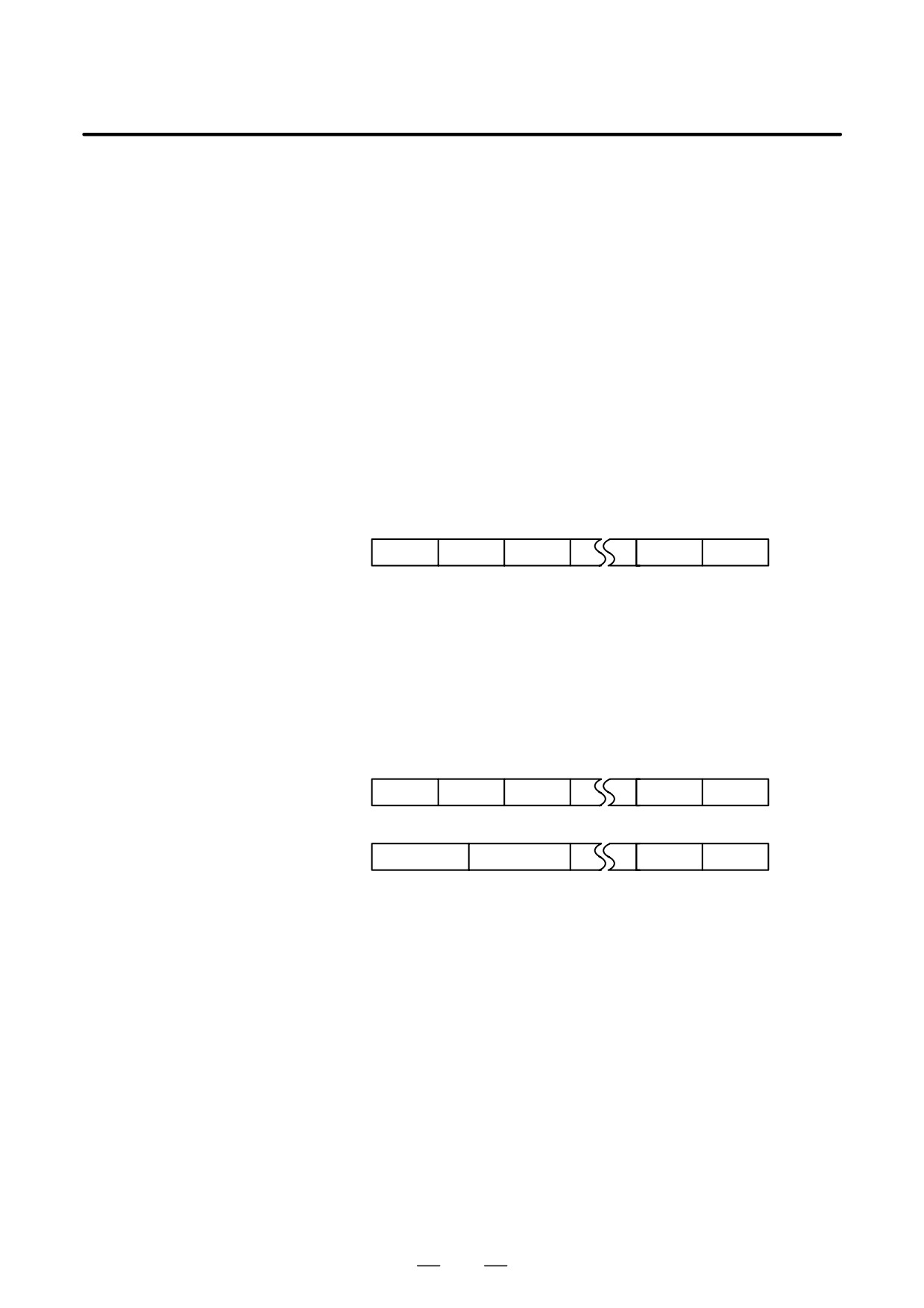
D What is a File
The unit of data, which is input/output between the floppy and the CNC
by one input/output operation (pressing the VREADW or VPUNCHW
key), is called a HfileI. When inputting CNC programs from, or
outputting them to the floppy, for example, one or all programs within the
CNC memory are handled as one file.
Files are assigned automatically file numbers 1,2,3,4 and so on, with the
lead file as 1.
File 1
File 2
File 3
File n
Blank
D Request for floppy
When one file has been entered over two floppies, LEDs on the adaptor
replacement
flash alternately on completion of data input/output between the first
floppy and the CNC, prompting floppy replacement. In this case, take the
first floppy out of the adaptor and insert a second floppy in its place. Then,
data input/output will continue automatically.
Floppy replacement is prompted when the second floppy and later is
required during file search-out, data input/output between the CNC and
the floppy, or file deletion.
Floppy 1
File 1
File 2
File 3
File (k-1)
File k
Floppy 2
Continuation of
File (k+1)
File n
Blank
file k
Since floppy replacement is processed by the input/output device, no
special operation is required. The CNC will interrupt data input/output
operation until the next floppy is inserted into the adaptor.
When reset operation is applied to the CNC during a request for floppy
replacement, the CNC is not reset at once, but reset after the floppy has
been replaced.
870
B-63534EN/02
OPERATION
8. DATA INPUT/OUTPUT
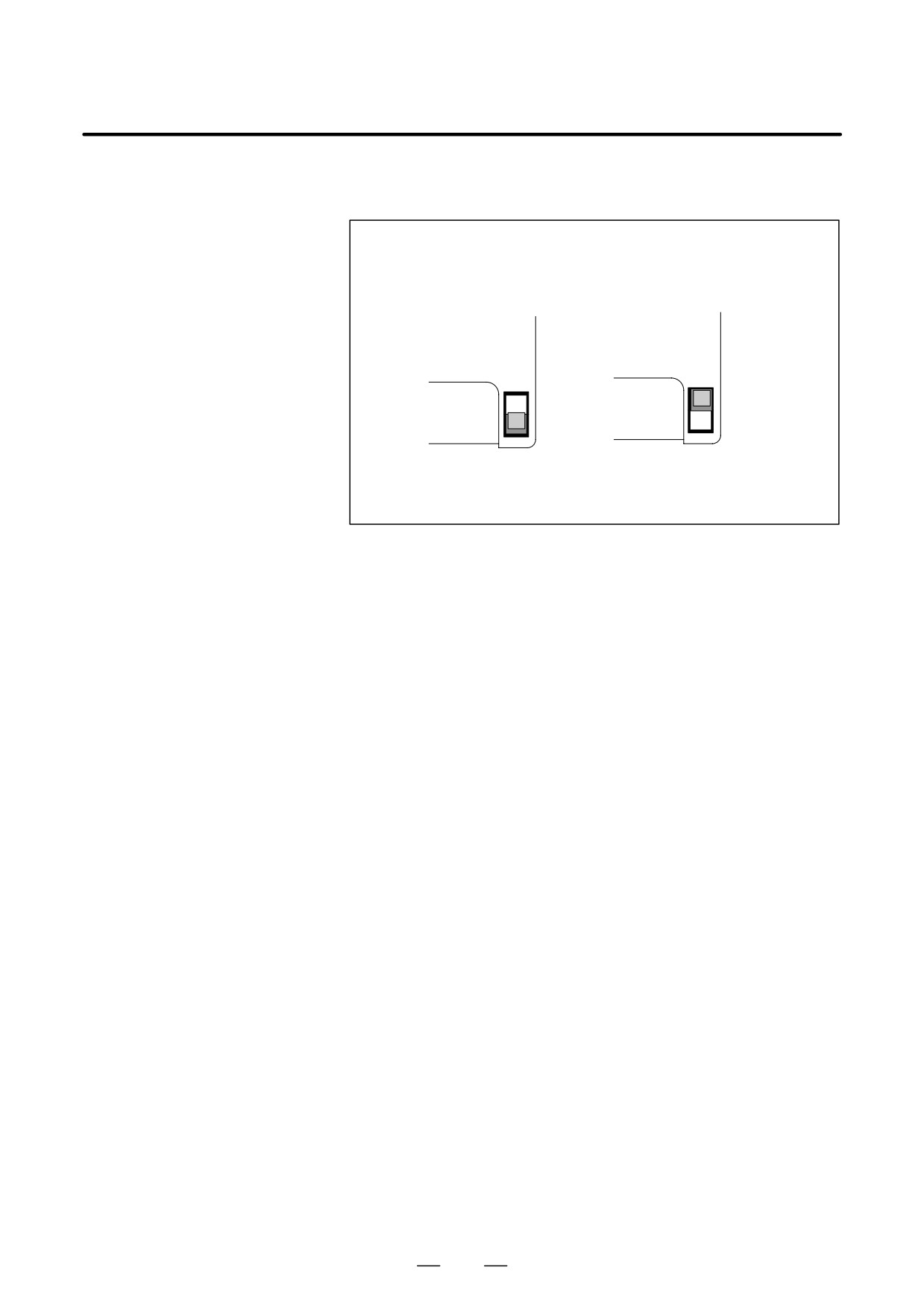
D Protect switch
The floppy is provided with the write protect switch. Set the switch to
the write enable state. Then, start output operation.
Write protect switch of a cassette
(1) Write-protected
(2) Write-enabled
(Only reading is
(Reading, writing,
possible.)
and deletion are possible.)
Fig. 8.1 Protect swtich
D Writing memo
Once written in the cassette or card, data can subsequently be read out by
correspondence between the data contents and file numbers. This
correspondence cannot be verified, unless the data contents and file
numbers are output to the CNC and displayed. The data contents can be
displayed with display function for directory of floppy disk
(See Section III-8.8).
To display the contents,write the file numbers and the contents on the
memo column which is the back of floppy.
(Entry example on MEMO)
File 1
CNC parameters
File 2
Offset data
File 3
NC program O0100
⋅
⋅
⋅
⋅
⋅
⋅
File (n-1)
NC program O0500
File n
NC program O0600
871
8. DATA INPUT/OUTPUT
OPERATION
B-63534EN/02
8.2
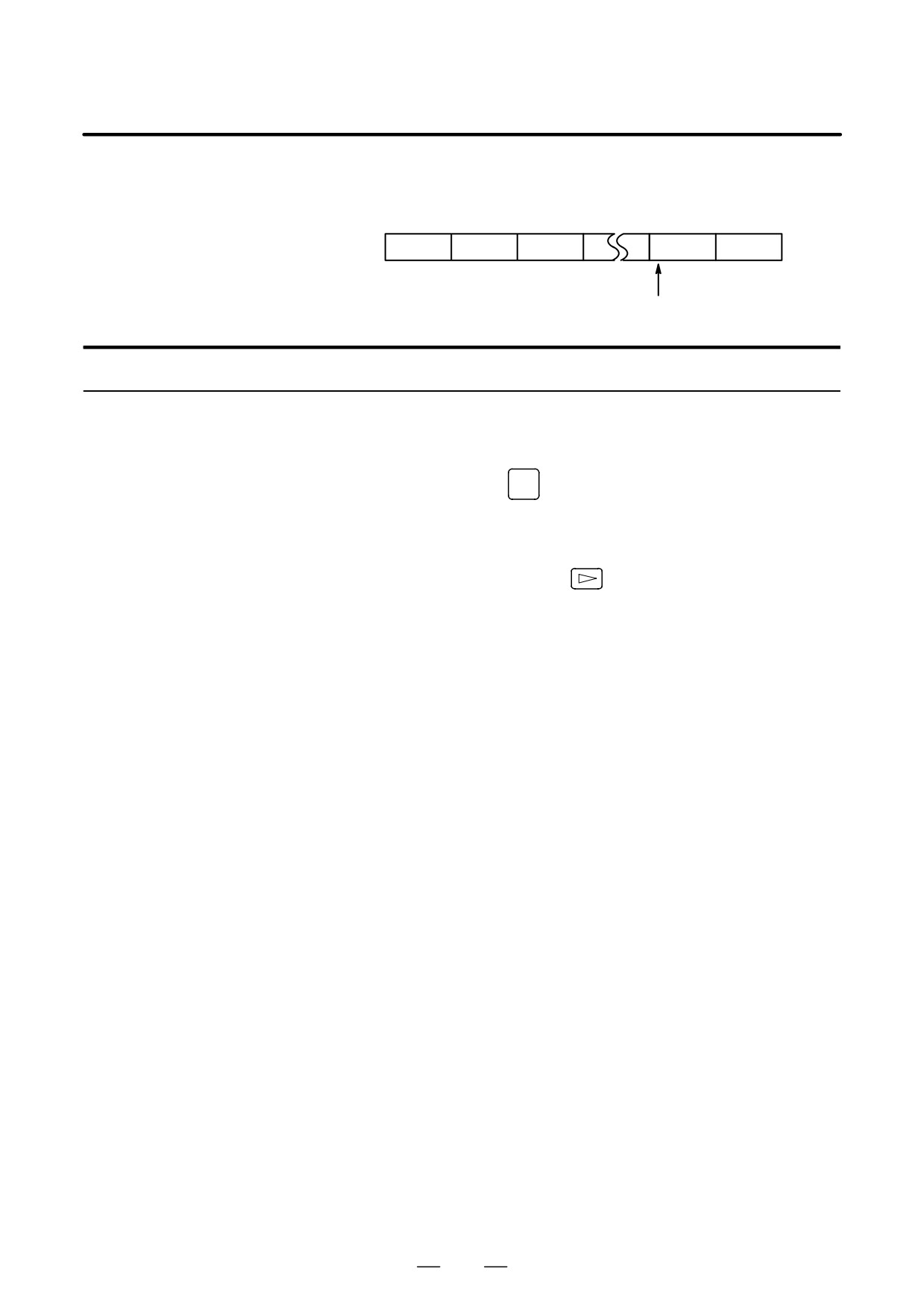
When the program is input from the floppy, the file to be input first
must be searched.
FILE SEARCH
For this purpose, proceed as follows:
File 1
File 2
File 3
File n
Blank
File searching of the file n
File heading
Procedure
1
Press the EDIT or MEMORY switch on the machine operator’s
panel.
2
Press function key
PROG
, then the program contents display screen or
program check screen appears.
3
Press soft key [(OPRT)].
4
Press the rightmost soft key
(next-menu key).
5
Enter address N.
6
Enter the number of the file to search for.
⋅ N0
The beginning of the cassette or card is searched.
⋅ One of N1 to N9999
Of the file Nos. 1 to 9999, a designated file is searched.
⋅ N-9999
The file next to that accessed just before is searched.
⋅ N-9998
When N-9998 is designated, N-9999 is automatically inserted
each time a file is input or output. This condition is reset by the
designation of N1,N1 to 9999, or N*9999 or reset.
7
Press soft keys [F SRH] and [EXEC].
The specified file is searched for.
Explanation
D File search by N-9999
The same result is obtained both by sequentially searching the files by
specifying Nos. N1 to N9999 and by first searching one of N1 to N9999
and then using the N-9999 searching method. The searching time is
shorter in the latter case.
872

B-63534EN/02
OPERATION
8. DATA INPUT/OUTPUT
Alarm
Alarm No.
Description
The ready signal (DR) of an input/output device is off.
An alarm is not immediately indicated in the CNC even when an
alarm occurs during head searching (when a file is not found, or
86
the like).
An alarm is given when the input/output operation is performed
after that. This alarm is also raised when N1 is specified for writ-
ing data to an empty floppy. (In this case, specify No.)
873

8. DATA INPUT/OUTPUT
OPERATION
B-63534EN/02
8.3
Files stored on a floppy can be deleted file by file as required.
FILE DELETION
File deletion
Procedure
1
Insert the floppy into the input/output device so that it is ready for
writing.
2
Press the EDIT switch on the machine operator’s panel.
3
Press function key
PROG
, then the program contents display screen
appears.
4
Press soft key [(OPRT)]
5
Press the rightmost soft key
(next-menu key).
6
Enter address N.
7
Enter the number (from 1 to 9999) of the file to delete.
8
Press soft key [DELETE] and then press soft key [DELETE].
The file specified in step 7 is deleted.
Explanations
D File number after the file
When a file is deleted, the file numbers after the deleted file are each
is deleted
decremented by one. Suppose that a file numbered k was deleted. In this
case, files are renumbered as follows:
Before deletion
after deletion
1 to (k>1)
1 to (k>1)
k
Deleted
(k+1) to n
k to (n>1)
D Protect switch
Set the write protect switch to the write enable state to delete the files.
874
B-63534EN/02
OPERATION
8. DATA INPUT/OUTPUT
8.4
PROGRAM
INPUT/OUTPUT
8.4.1
This section describes how to load a program into the CNC from a floppy
or NC tape.
Inputting a Program
Inputting a program
Procedure
1
Make sure the input device is ready for reading.
For the two-path control, select the tool post for which a program to
be input is used with the tool post selection switch.
2
Press the EDIT switch on the machine operator’s panel.
3
When using a floppy, search for the required file according to the
procedure in III-8.2.
4
Press function key
PROG
, then the program contents display screen or
program directory screen appears.
5
Press soft key [(OPRT)].
6
Press the rightmost soft key
(next-menu key).
7
After entering address O, specify a program number to be assigned to
the program. When no program number is specified here, the
program number used on the floppy or NC tape is assigned.
8
Press soft keys [READ] and [EXEC]
The program is input and the program number specified in step 7 is
assigned to the program.
Explanations
D Collation
If a program is input while the data protect key on the machine operator’s
panel turns ON, the program loaded into the memory is verified against
the contents of the floppy or NC tape.
If a mismatch is found during collation, the collation is terminated with
an alarm (P/S No. 079).
If the operation above is performed with the data protection key turns
OFF, collation is not performed, but programs are registered in memory.
D Inputting multiple
When a tape holds multiple programs, the tape is read up to ER (or %).
programs from an NC
tape
O1111 M02;
O2222 M30;
O3333 M02;
ER(%)
875

8. DATA INPUT/OUTPUT
OPERATION
B-63534EN/02
D Program numbers on a
• When a program is entered without specifying a program number.
NC tape
⋅
The O-number of the program on the NC tape is assigned to the
program.
If the program has no O-number, the N-number in the first block is
assigned to the program.
⋅
When the program has neither an O-number nor N-number, the
previous program number is incremented by one and the result is
assigned to the program.
⋅
When the program does not have an O-number but has a five-digit
sequence number at the start of the program, the lower four digits of
the sequence number are used as the program number. If the lower
four digits are zeros, the previously registered program number is
incremented by one and the result is assigned to the program.
• When a program is entered with a program number
The O-number on the NC tape is ignored and the specified number is
assigned to the program. When the program is followed by additional
programs, the first additional program is given the program number.
Additional program numbers are calculated by adding one to the last
program.
D Program registration in
The method of registration operation is the same as the method of
the background
foreground operation. However, this operation registers a program in the
background editing area. As with edit operation, the operations described
below are required at the end to register a program in foreground program
memory.
[(OPRT)] [BG-END]
D Additional program input
You can input a program to be appended to the end of a registered
program.
Registered program
Input program
Program after input
f1234 ;
f5678 ;
f1234 ;
jjjjjjj ;
fffffff ;
jjjjjjj ;
jjjjj ;
fffff ;
jjjjj ;
jjjj ;
ffff ;
jjjj ;
jjj ;
fff ;
jjj ;
%
%
%
f5678 ;
fffffff ;
fffff ;
ffff ;
fff ;
%
In the above example, all lines of program O5678 are appended to the end
of program O1234. In this case, program number O5678 is not registered.
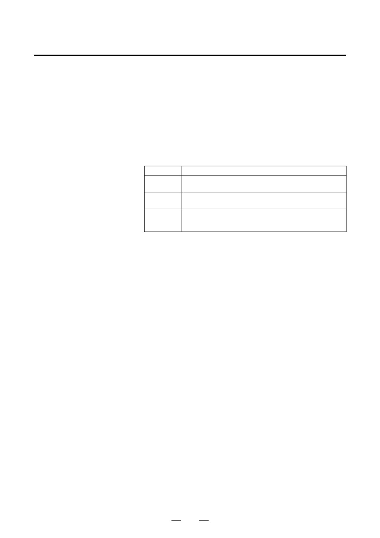
When inputting a program to be appended to a registered program, press
the [READ] soft key without specifying a program number in step 8.
Then, press the [CHAIN] and [EXEC] soft keys.
S In entire program input, all lines of a program are appended, except for
its O number.
S When canceling additional input mode, press the reset key or the [CAN]
or [STOP] soft key.
876
B-63534EN/02
OPERATION
8. DATA INPUT/OUTPUT
S Pressing the [CHAIN] soft key positions the cursor to the end of the
registered program. Once a program has been input, the cursor is
positioned to the start of the new program.
S Additional input is possible only when a program has already been
registered.
D Defining the same
If an attempt has been made to register a program having the same number
program number as that
as that of a previously registered program, P/S alarm 073 is issued and the
of an existing program
program cannot be registered.
Alarm
Alarm No.
Description
The size of memory is not sufficient to store the input pro-
70
grams
An attempt was made to store a program with an existing pro-
73
gram number.
The verification operation found a mismatch between a pro-
79
gram loaded into memory and the contents of the program on
the floppy or NC tape.
877

8. DATA INPUT/OUTPUT
OPERATION
B-63534EN/02
8.4.2
A program stored in the memory of the CNC unit is output to a floppy or
NC tape.
Outputting a Program
Outputting a program
Procedure
1
Make sure the output device is ready for output.
For the two-path control, select the tool post for which a program to
be output is used with the tool post selection switch.
2
To output to an NC tape, specify the punch code system (ISO or EIA)
using a parameter.
3
Press the EDIT switch on the machine operator’s panel.
4
Press function key
PROG
, then the program contents display screen or
program directory screen appears.
5
Press soft key [(OPRT)].
6
Press the rightmost soft key
(next-menu key).
7
Enter address O.
8
Enter a program number. If -9999 is entered, all programs stored in
memory are output.
To output multiple programs at one time, enter a range as follows :
O∆∆∆∆,OVVVV
Programs No.∆∆∆∆ to No.VVVV are output.
The program library screen displays program numbers in ascending
order when bit 4 (SOR) of parameter No. 3107 is set to 1.
9
Press soft keys [PUNCH] and [EXEC]
The specified program or programs are output.
Explanations
(Output to a floppy)
D File output location
When output is conducted to the floppy, the program is output as the new
file after the files existing in the floppy. New files are to be written from
the beginning with making the old files invalid, use the above output
operation after the N0 head searching.
D An alarm while a
When P/S alarm (No. 86) occurs during program output, the floppy is
program is output
restored to the condition before the output.
D Outputting a program
When program output is conducted after N1 to N9999 head searching, the
after file heading
new file is output as the designated n-th position. In this case, 1 to n-1
files are effective, but the files after the old n-th one are deleted. If an
alarm occurs during output, only the 1 to n-1 files are restored.
D Efficient use of memory
To efficiently use the memory in the cassette or card, output the program
by setting parameter NFD (No. 0101#7,No. 0111#7 or 0121#7) to 1. This
parameter makes the feed is not output, utilizing the memory efficiently.
878
B-63534EN/02
OPERATION
8. DATA INPUT/OUTPUT
D On the memo record
Head searching with a file No. is necessary when a file output from the
CNC to the floppy is again input to the CNC memory or compared with
the content of the CNC memory. Therefore, immediately after a file is
output from the CNC to the floppy, record the file No. on the memo.
D Punching programs in
Punch operation can be performed in the same way as in the foreground.
the background
This function alone can punch out a program selected for foreground
operation.
<O> (Program No.) [PUNCH] [EXEC]: Punches out a specified program.
<O> H-9999I [PUNCH] [EXEC]: Punches out all programs.
Explanations
(Output to an NC tape)
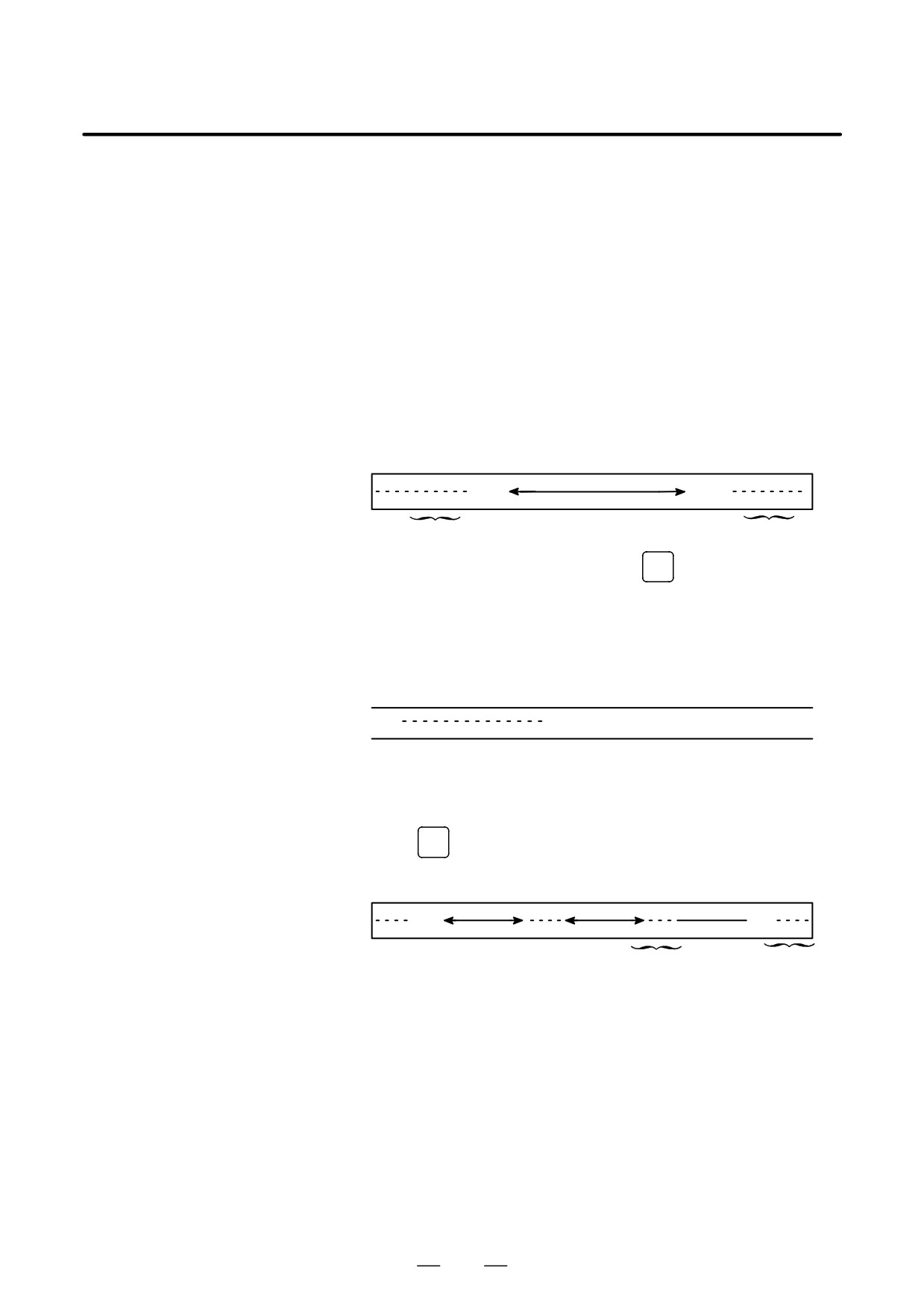
D Format
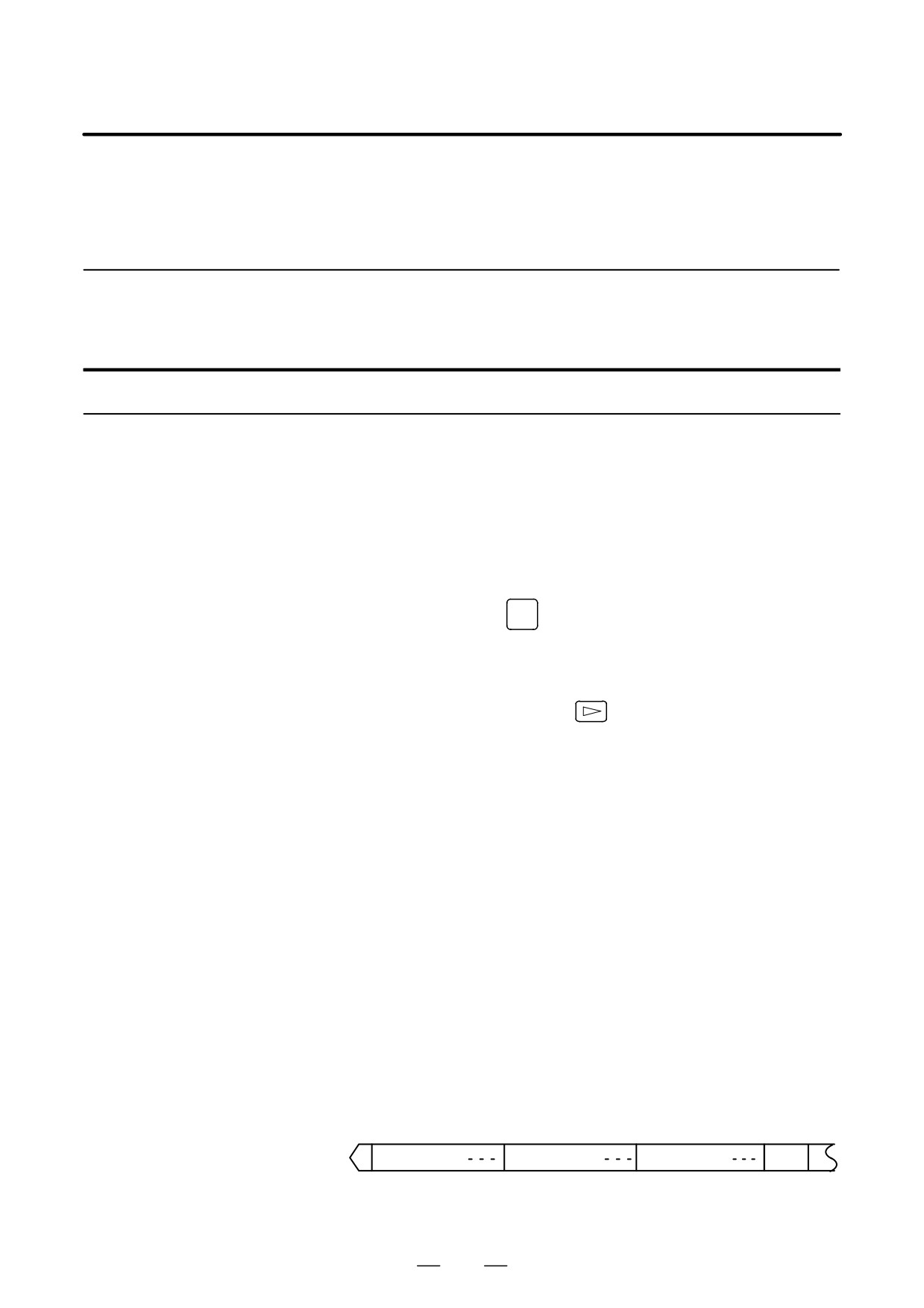
A program is output to paper tape in the following format:
ER
Program
ER
(%)
(%)
Feed of 3 feet
Feed of 3 feet
If three-feet feeding is too long, press the
CAN
key during feed
punching to cancel the subsequent feed punching.
D TV check
A space code for TV check is automatically punched.
D ISO code
When a program is punched in ISO code, two CR codes are punched after
an LF code.
LF CR CR
By setting NCR (bit 3 of parameter No. 0100), CRs can be omitted so that
each LF appears without a CR.
D Stopping the punch
Press the
RESET
key to stop punch operation.
D Punching all programs
All programs are output to paper tape in the following format.
ER
Program
Program
Program
ER
(%)
(%)
Feed of 1-feet
Feed of 3-feet
The sequence of the programs punched is undefined.
879