FANUC Series 16i/160i/160is-MB, Series 18i/180i/180is-MB5, Series 18i/180i/180is-MB. Operator's Manual - page 29
OPERATION
4. AUTOMATIC OPERATION
B-63534EN/02
2-4 Move the cursor to the mirror image setting position, then set the
target axis to 1.
3
Enter an automatic operation mode (memory mode or MDI mode),
then press the cycle start button to start automatic operation.
Explanations
D The mirror image function can also be turned on and off by setting bit
0 of parameter 0012 (MIRx) to 1 or 0.
D For the mirror image switches, refer to the manual supplied by the
machine tool builder.
Limitations
The direction of movement during manual operation, the direction of
movement from an intemidiate point to the reference position during
automatic reference position return (G28), the direction of approach
during unidirectional positioning (G60), and the shift direction in a boring
cycle (G76, G87) cannot be reserved.
820
OPERATION
B-63534EN/02
4. AUTOMATIC OPERATION
The tool can be withdrawn from a workpiece in order to replace the tool
4.10
when it is damaged during machining, or merely to check the status of
TOOL WITHDRAWAL
machining. The tool can then be advanced again to restart machining
AND RETURN
efficiently.
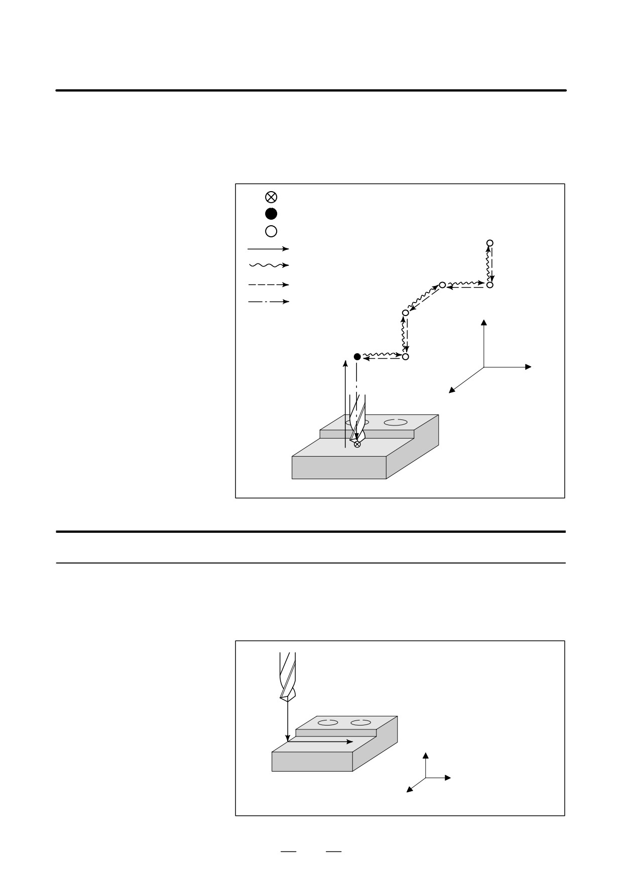
: Position where the TOOL WITHDRAW switch is turned on
: Programmed position
: Position to which the tool is retracted by manual operation
: Retraction path
: Manual operation (withdraw path)
: Return path
: Repositioning
Z
X
Y
Procedure for tool withdrawal and return
Procedure1
Specify a retraction axis and distance in command G10.6IP_
Programming
beforehand.In the sample program below, the N20 block specifies that the
Z-axis is the retraction axis and the retraction distance is to be 50 mm.
(Sample program)
N10 G91 Z-50. ;
N20 G10.6 Z50. ;
N10
N30 G01 X150. F500. ;
N30
Z
X
Y
821
OPERATION
4. AUTOMATIC OPERATION
B-63534EN/02
Procedure2
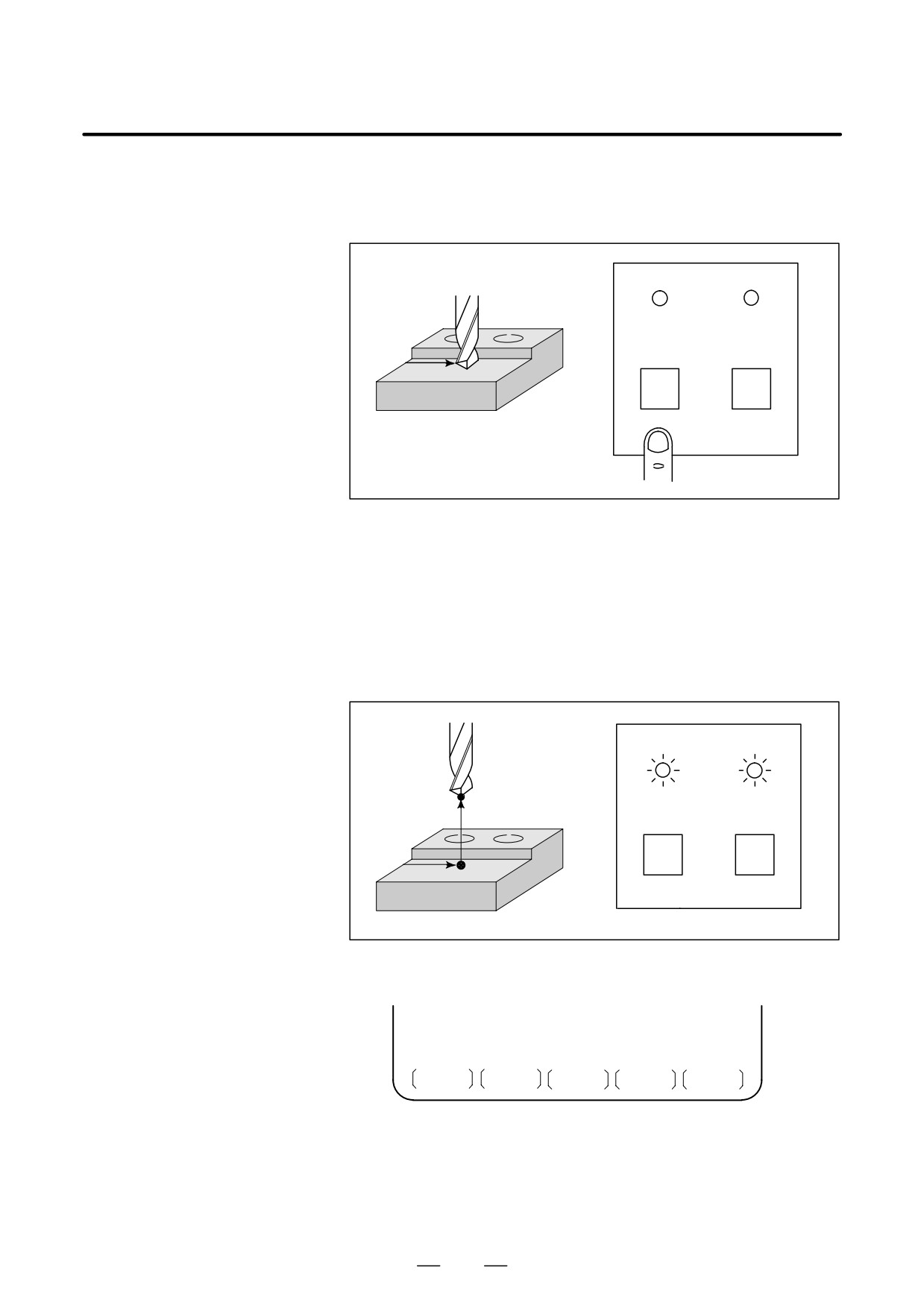
Suppose that the TOOL WITHDRAW switch on the machine operator’s
Retract
panel is turned on when the tool is positioned at point A during execution
of the N30 block.
Machine operator’s panel
TOOL
RETRAC-
BEING
TION
WITH-
POSITION
DRAWN
A
TOOL
TOOL
WITH-
RETURN
N30
DRAW
Next, the tool withdrawal mode is set and the TOOL BEING
WITHDRAWN LED goes on. At this time, automatic operation is
temporarily halted. The tool is then retracted by the programmed
distance. If point A is the end point of the block, retraction is performed
after automatic operation is stopped.Retraction is based on linear
interpolation.
The dry run feedrate is used for retraction.Upon
completion of retraction, the RETRACT POSITION LED on the
operator’s panel goes on.
Machine operator’s panel
TOOL BE-
RETRAC-
Point E
ING WITH-
TION
DRAWN
POSITION
TOOL
TOOL
WITH
A
DRAW
RETURN
N30
Screen
During retraction, the screen displays PTRR and STRT.
MEM STRT MTN ***
0 : 00 : 00 PTRR
S PTRR blinks in the field for indicating states such as the program
editing status.
S STRT is displayed in the automatic operation status field.
S MTN is displayed in the field for indicating status such as movement
along an axis.
822
OPERATION
B-63534EN/02
4. AUTOMATIC OPERATION
Procedure3
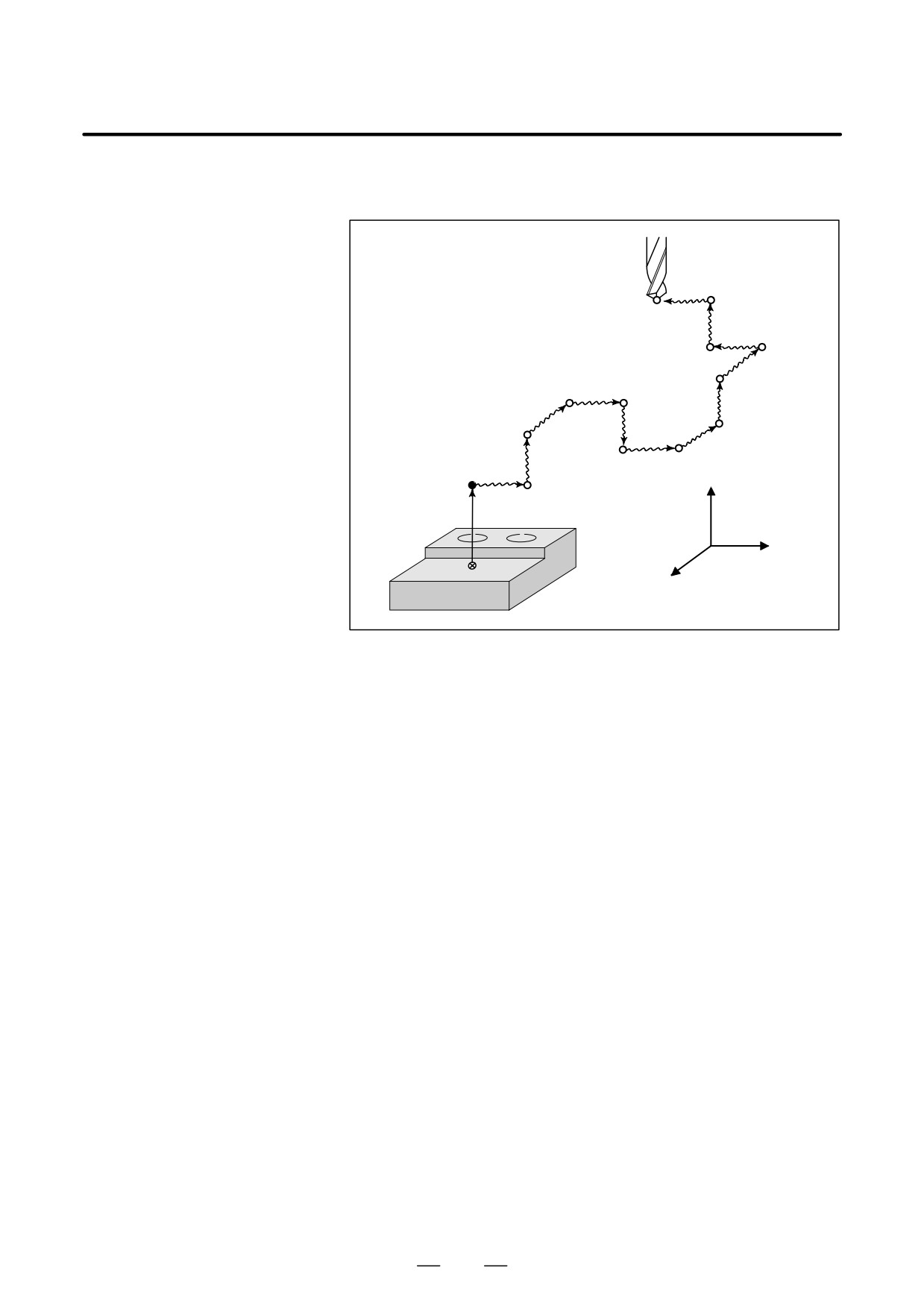
Set the manual operation mode, then withdraw the tool. For manual
Withdrawal
operation, either jog feed or handle feed is possible.
11
12
10
9
8
3
4
7
2
5
6
Z
E point
1
X
A point
Y
823
OPERATION
4. AUTOMATIC OPERATION
B-63534EN/02
Procedure4
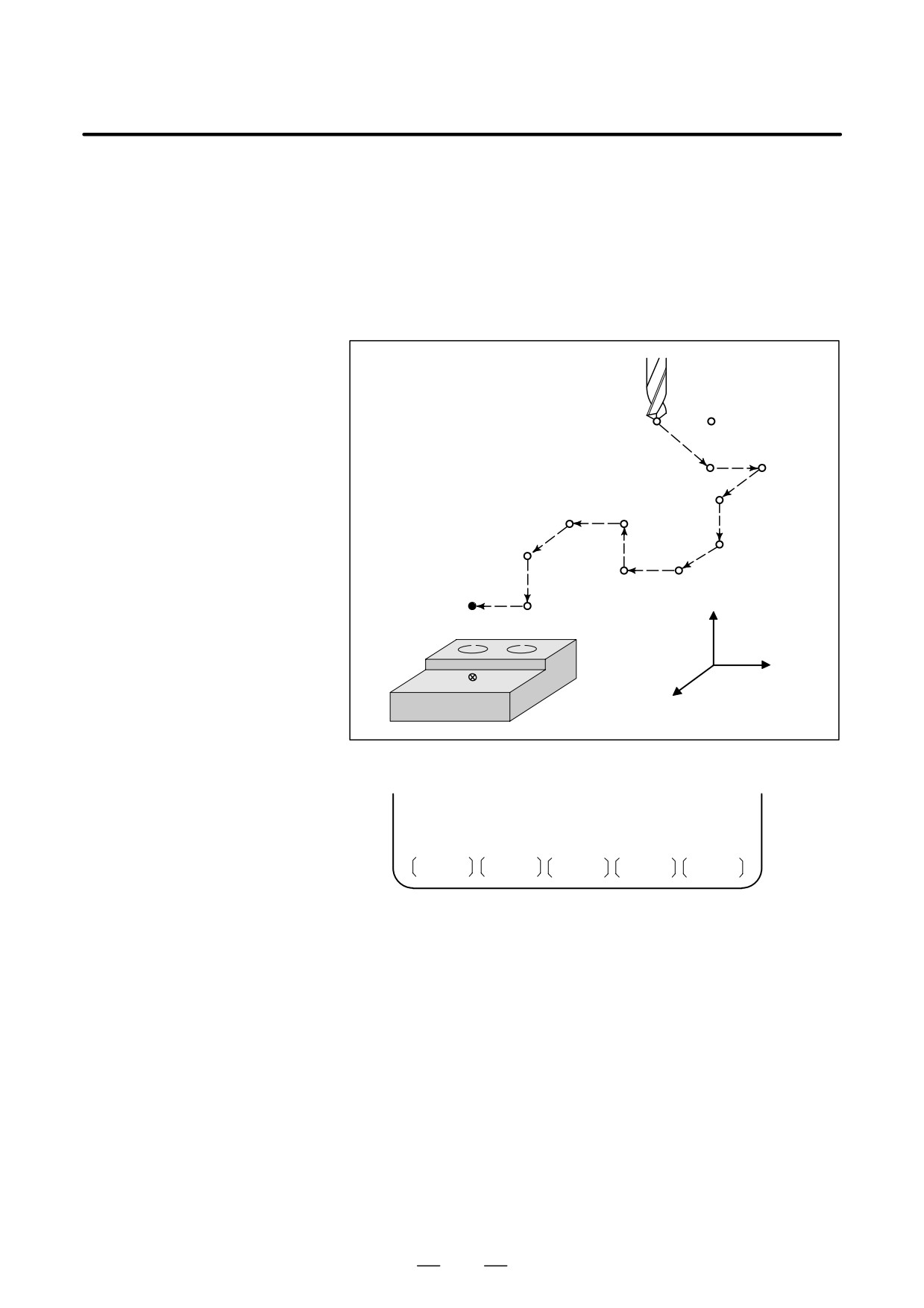
After withdrawing the tool and any additional operation such as replacing
Return
the tool, move the tool back to the previous retraction position.
To return the tool to the retraction position, return the mode to automatic
operation mode, then turn the TOOL RETURN switch on the operator’s
panel on then off again. The tool returns to the retraction position at the
dry run feedrate, regardless of whether the dry run switch is on or off.
When the tool has returned to the retraction position, the RETRACTION
POSITION LED comes on.
12
11
9
10
8
3
4
7
2
5
6
Z
E point
1
X
A point
Y
Screen
During return operation, the CRT screen displays PTRR and MSTR.
MEM MSTR MTN ***
0 : 00 : 00 PTRR
S PTRR blinks in the field for indicating states such as program editing
status.
S MSTR is displayed in the automatic operation status field.
S MTN is displayed in the field for indicating states such as movement
along an axis.
824
OPERATION
B-63534EN/02
4. AUTOMATIC OPERATION
Procedure 5
While the tool is at the retraction position (point E in the figure below)
Repositioning
and the RETRACTION POSITION LED is on, press the cycle start
switch. The tool is then repositioned at the point where retraction was
started (i.e. where the TOOL WITHDRAW switch was turned on).
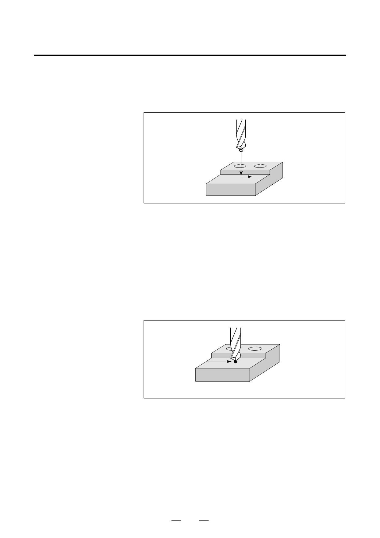
E point
⊗
N30A
Upon completion of repositioning, the tool withdraw mode is cancelled,
and the TOOL BEING WITHDRAWN LED goes off and restart N30.
Explanation 1
Retraction
D When no retraction
If no retraction distance or direction required for retraction are specified,
distance is specified
retraction is not performed when the TOOL WITHDRAW switch on the
operator’s panel is turned on. Instead, the block being executed in
automatic operation is interrupted
(automatic operation is held or
stopped). In this state, the tool can be withdrawn and returned.
E point
N30A point
D Retraction from the
When the single block switch is turned on during automatic operation, or
automatic operation
the TOOL WITHDRAW switch is turned on after the automatic operation
hold or stop state
hold or stop state is set by feed hold: Retraction is performed, then the
automatic operation hold or stop state is set again.
D Stopping retraction
During retraction, feed hold operation is ignored. However, reset
operation is enabled (retraction is stopped at reset). When an alarm is
issued during retraction, the retraction is stopped immediately.
D Repositioning
After retraction is completed, tool repositioning can be started without
immediately after
performing the withdraw and return operations.
retraction
825
OPERATION
4. AUTOMATIC OPERATION
B-63534EN/02
Explanation 2
Withdrawal
D Axis selection
To move the tool along an axis, select the corresponding axis selection
signal. Never specify axis selection signals for two or more axes at a time.
D Path memorization
When the tool is moved in manual operation along an axis, the control unit
memorizes up to ten paths of movements. If the tool is stopped after being
moved along a selected axis and is then moved along another selected
axis, the position where this switch takes place is memorized. After ten
paths have been memorized, the control unit does not memorize any
additional switching points.
D Reset
Upon reset, memorized position data is lost and the tool withdraw mode
is cancelled.
Explanaiton 3 Return
D Return path
When there are more than ten return paths, the tool first moves to the tenth
position, then to the ninth position, then to the eighth position, and so
forth until the retraction position is reached.
D Single block
The single block switch is enabled during return operation. If the single
block switch is turned off, continuous return operation is performed. If
the single block switch is turned off, the tool stops at each memorized
position. In this case, return operation can be resumed by turning the
TOOL RETURN switch on then off again.
D Interruption of return
When an alarm is issued during return operation, return operation stops.
operation
D Feed hold
The feed hold function is enabled during return operation.
Explanation 4
Repositioning
D Feed hold
The feed hold function is disabled during repositioning.
D Operation after
The operation after completion of repositioning depends on the automatic
completion of
operation state present when the TOOL WITHDRAW switch is turned on.
repositioning
1. When automatic operation is being started
After completion of repositioning, the interrupted execution of the
block is resumed.
2. When automatic operation is held or stopped
After completion of repositioning, the tool stops once at the
repositioned point, then the original automatic operation hold or stop
state is set. When the cycle start switch is pressed, automatic operation
is resumed.
826
OPERATION
B-63534EN/02
4. AUTOMATIC OPERATION
With the retrace function, the tool can be moved in the reverse direction
4.11
(reverse movement) by using the REVERSE switch during automatic
RETRACE FUNCTION
operation to trace the programmed path. The retrace function also enables
the user to move the tool in the forward direction again (forward return
movement) along the retraced path until the retrace start position is
reached. When the tool reaches the retrace start position, the tool resumes
movement according to the program.
Procedure for Retrace Operation
Procedure
D Forward movement →
To move the tool in the forward direction, turn off the REVERSE switch
Reverse movement
on the operator’s panel, then press the cycle start switch. If the REVERSE
switch on the operator’s panel is on, the tool moves in the reverse direction
or completes reverse movement.
Three methods are available for moving the tool in the reverse direction
along the programmed path.
1) When the tool is moving in the forward direction, turn on the
REVERSE switch on the operator’s panel during block execution.
2) When the tool is moving in the forward direction, turn on the
REVERSE switch on the operator’s panel after a single block stop.
3) When the tool is moving in the forward direction, turn on the
REVERSE switch on the operator’s panel after a feed hold stop.
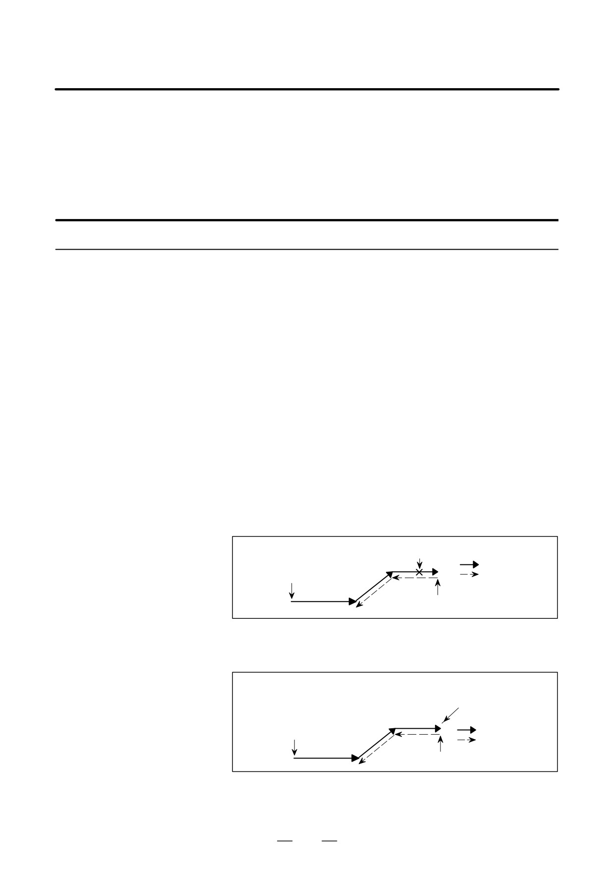
In the case of 1) above, the tool starts reverse movement after completion
of the block currently being executed (after execution up to the position
of a single block stop). Turning on the REVERSE switch on the
operator’s panel does not immediately start reverse movement.
REVERSE swtch rurned on
Cycle start
Forward movement
(forward movement started)
Reverse movement
Reverse movement started
In the case of 2) above, the tool starts reverse movement at the position
of a single block stop when the cycle start switch is pressed.
Single block stop
REVERSE switch
turned on cycle start
Cycle start
Forward movement
(forward movement started)
Reverse movement
Reverse movement started
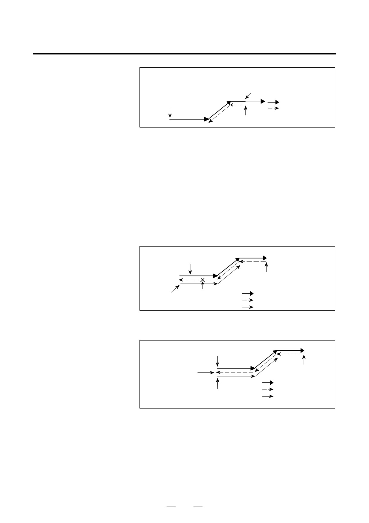
In the case of 3) above, the tool starts reverse movement at the position
of a feed hold stop when the cycle start switch is pressed.
827
OPERATION
4. AUTOMATIC OPERATION
B-63534EN/02
Feed hold stop
REVERSE switch
rurned on cycle start
Cycle start
Forward movement
(forward movement started)
Reverse movement
Reverse movement started
D Reverse movement →
Three methods are available for moving the tool in the forward direction
Forward return movement
again along the retraced path.
1) When the tool is moving in the reverse direction, turn off the
REVERSE switch on the operator’s panel during block execution.
2) When the tool is moving in the reverse direction, turn off the
REVERSE switch on the operator’s panel after a single block stop.
3) When the tool is moving in the reverse direction, turn off
theREVERSE switch on the operator’s panel after a feed hold stop.
In the case of 1) above, the tool starts forward return movement after
completion of the block currently being executed (after execution up to
the position of a single block stop). Turning off the REVERSE switch on
the operator’s panel does not immediately start forward return movement.
Cycle start
(forward movement started)
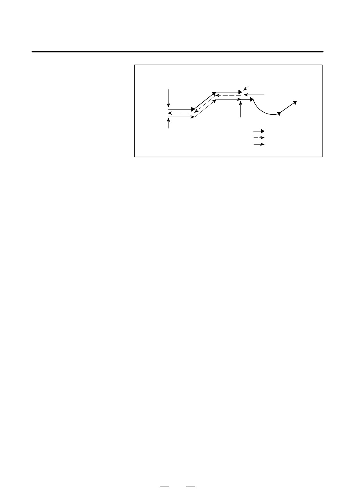
Reverse movement
started
Forward return
REVERSE
Forward movement
movement
switch
Reverse movement
started
turned off
Forward return movement
In the case of 2) above, the tool starts forward return movement at the
position of a single block stop when the cycle start switch is pressed.
Cycle start
(forward movement started)
Single block stop
REVERSE switch
Reverse movement
turned off
started
Cycle start
Forward movement
Reverse movement
Forward return movement started
Forward return
movemnt
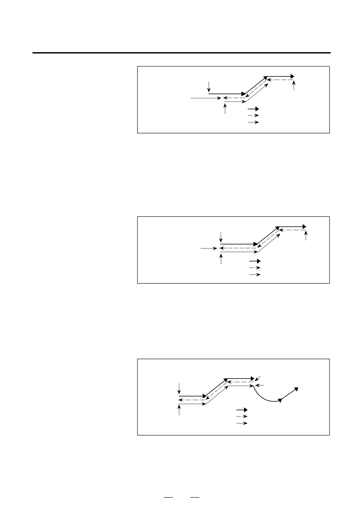
In the case of 3) above, the tool starts forward return movement at the
position of a feed hold stop when the cycle start switch is pressed.
828
OPERATION
B-63534EN/02
4. AUTOMATIC OPERATION
Cycle start
(forward movement started)
Reverse movement
Feed hold stop
started
REVERSE
Forward movement
switch turned off
Cycle start
Reverse movement
Forward return
Forward return
movement started
movement
D Reverse movement →
When there are no more blocks for which to perform reverse movement
Reverse movement
(when the tool has moved back to the initial forward movement block or
completion → Forward
the tool has not yet started forward movement), the reverse movement
return movement
completion state is entered and operation stops.
Even when the cycle start switch is pressed with the REVERSE switch
on the operator’s panel turned on, no operation is performed (the reverse
movement completion state remains unchanged). When the cycle start
switch is pressed after turning off the REVERSE switch on the operator’s
panel, the tool starts forward return movement or forward movement.
Cycle start
(forward movement started)
Reverse movement
Reverse movement
started
completed
REVERSE switch
Forward movement
turned off
Reverse movement
Forward return
Cycle start
Forward return movement
movement
started
D Forward return movement
When the tool completes a forward return movement up to the block
→ Forward movement
where reverse movement was started, the tool automatically resumes
forward movement. Programmed commands are read and program
execution is continued. No particular operation is required to resume
forward movement.
When tool movement switches from forward return movement to forward
movement, the display of RTRY (Re-TRY) in the lower-right corner of
the CRT screen disappears.
Cycle start
Reverse movement started
(forward movement started)
Forward movement
started
Forward movement
Reverse movement
Forward return movement started
Forward return movement
If the tool moves in the reverse direction after a feed hold stop, the tool
stops forward return movement at the position of the feed hold stop, then
resumes forward movement. If the tool moves in the reverse direction
after a single block stop, the tool also stops forward return movement at
the position of the single block stop.
829
OPERATION
4. AUTOMATIC OPERATION
B-63534EN/02
Feed hold stop
Reverse movement
Cycle start
(forward movement started)
signal=1,cycle start
Reverse movement
started
Forward movement started
Forward movement
Forward return movement started
Reverse movement
Forward return
movement
Explanations
D Forward movement and
In automatic operation, a program is usually executed in the order that
reverse movement
commands are specified. This mode of execution is referred to as forward
movement. The retrace function can execute in reverse, program blocks
that have already been executed. This mode of execution is referred to as
reverse movement. In reverse movement, the tool can retrace the tool path
followed by forward movement.
A program can be executed in the reverse direction only for those blocks
that have already been executed in the forward direction.
Approximately 40 to 80 blocks can be executed in the reverse direction,
depending on the program.
During reverse movement, the REVERSE MOVEMENT LED is on and
RVRS blinks in the lower-right corner of the screen to indicate that the
tool is undergoing reverse movement.
The tool can perform reverse movement one block at a time when the
single block mode is set.
D Forward return
The tool can be moved again along the retraced path of the blocks in the
movement
forward direction up to the block where reverse movement was started.
This movement is referred to as forward return movement. In forward
return movement, the tool moves along the same path as forward
movement up to the position where reverse movement started.
When the tool returns to the block where reverse movement was started,
the tool resumes forward movement according to the program.
In forward return movement, the REVERSE MOVEMENT LED is off
and RTRY (Re-TRY) blinks in the lower-right corner of the screen to
indicate that the tool is undergoing forward return movement. When the
tool switches from forward return movement to forward movement,
RTRY (Re-TRY) disappears from the lower-right corner of the screen.
The tool can perform forward return movement one block at a time when
the single block mode is set.
D Reverse movement
When there are no more blocks for which to perform reverse movement
completion
(when the tool has moved back along the path of all memorized blocks
or the tool has not yet started forward movement), operation stops. This
is referred to as reverse movement completion.
Upon reverse movement completion, the REVERSE MOVEMENT LED
goes off, and RVED (ReVerse EnD) blinks in the lower-right corner of
the screen to indicate that reverse movement is completed.
830
OPERATION
B-63534EN/02
4. AUTOMATIC OPERATION
D Reset
Upon reset (when the RESET key on the MDI panel is pressed, the
external reset signal is applied, or the reset and rewind signal is applied),
the memorized reverse movement blocks are cleared.
D Feedrate
A feedrate for reverse movement can be specified using parameter (No.
1414). When this parameter is set to 0, the feedrate used for forward
movement is used.
For forward return movement, the feedrate for forward movement is
always used.
In reverse movement and forward return movement, the feedrate override
function, rapid traverse override function, and dry run function are
enabled.
Limitations
D Block that disables
Reverse movement stops when any of the commands or modes listed
reverse movement
below appears. If an attempt is made during forward movement to stop
forward movement with feed hold stop and then move the tool in the
reverse direction when any of the commands and modes below is
specified, the reverse movement completion state occurs.
⋅ Involute interpolation (G02.2/ G03.2)
⋅ Exponential interpolation (G02.3/ G03.3)
⋅ Cylindrical interpolation (G07.1, G107)
⋅ Polar coordinate interpolation mode (G12.1)
⋅ Inch/metric conversion (G20/ G21)
⋅ Reference position return check (G27)
⋅ Return to reference position (G28)
⋅ Return from reference position (G29)
⋅
2nd, 3rd, and 4th reference position return (G30)
⋅ Floating reference position return (G30.1)
⋅ Thread cutting (G33)
⋅ Machine coordinate system selection (G53)
⋅ Chopping operation command (G81.1)
(See the chopping function described later.)
⋅ Rigid tapping cycle (M29, G84)
⋅ High speed cycle machining (G05)
⋅ High speed remote buffer A (G05)
⋅ High speed remote buffer B (G05)
⋅ High precision contour control (RISC) (G05)
⋅ Advanced preview control (G08)
⋅ Cs contour control
831
OPERATION
4. AUTOMATIC OPERATION
B-63534EN/02
D Circular
Be sure to specify the radius of an arc with R.
interpolation(G02,G03)
WARNING
If an end point is not correctly placed on an arc (if a leading
line is produced) when an arc center is specified using I, J,
and K, the tool does not perform correct reverse movement.
D Interrupt-type custom
1. Never initiate an interrupt during reverse movement.
macro
2. Never perform reverse movement for an interrupte block and the
program that has issure the interrupt.
D Tool life management
The retrace function does not support the tool life management funciton.
D Switching automatic
If the operation mode is switched after a single block stop from memory
operation mode
operation to MDI operation or vice versa during reverse movement or
forward return movement, reverse movement, forward return movement,
and forward movement can no longer be performed. To restart operation,
return the mode to the original mode, then press the cycle start switch.
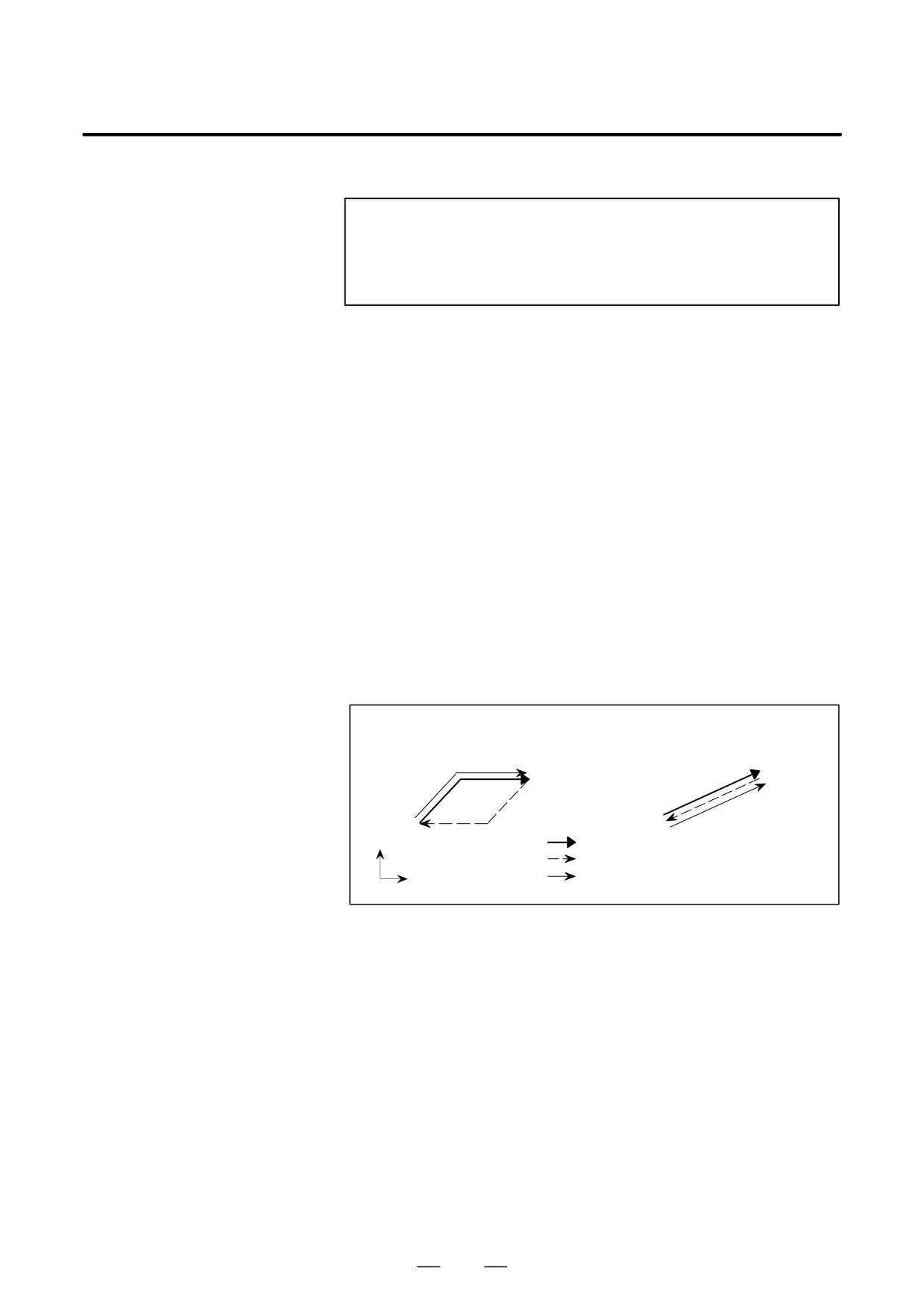
D Positioning (G00)
When the tool is positioned based on nonlinear interpolation by setting
bit 1 (LRP) of parameter No. 1401 to 0, the path of the tool for reverse
movement does not match the path for forward movement. The path for
forward return movement is the same as the path for forward movement.
When the tool is positioned based on linear interpolation by setting bit 1
(LRP) of parameter No. 1401 to 1, the path of the tool for reverse
movement matches the path for forward movement.
Positioning based on nonlinear
Positioning based on linear
interpolation (LRP=0)
interpolation (LRP=1)
Y
Forward movement
Reverse movement
Forward return
X
movement
D Dwell (G04)
The dwell command (G04) is executed in reverse movement and forward
return movement in the same way as during ordinary operation.
D Programmable data
A tool compensation value, parameter, pitch error data, workpiece zero
setting (G10)
point offset value, and tool life management setting specified or modified
using the programmable data setting code (G10) are ignored in reverse
movement and forward return movement.
D Stored stroke check
The on/off state of the stored stroke check function present at the end of
function on/off (G22,G23)
forward movement remains unchanged during reverse movement and
forward return movement. This means that the actual on/off state may
differ from the modal G22/G23 indication. When reverse movement or
forward return movement is cancelled upon reset, the modal G22/G23
indication at that time becomes valid.
The setting of an area with G22 X_Y_Z_I_J_K at the end of forward
movement remains unchanged.
832
OPERATION
B-63534EN/02
4. AUTOMATIC OPERATION
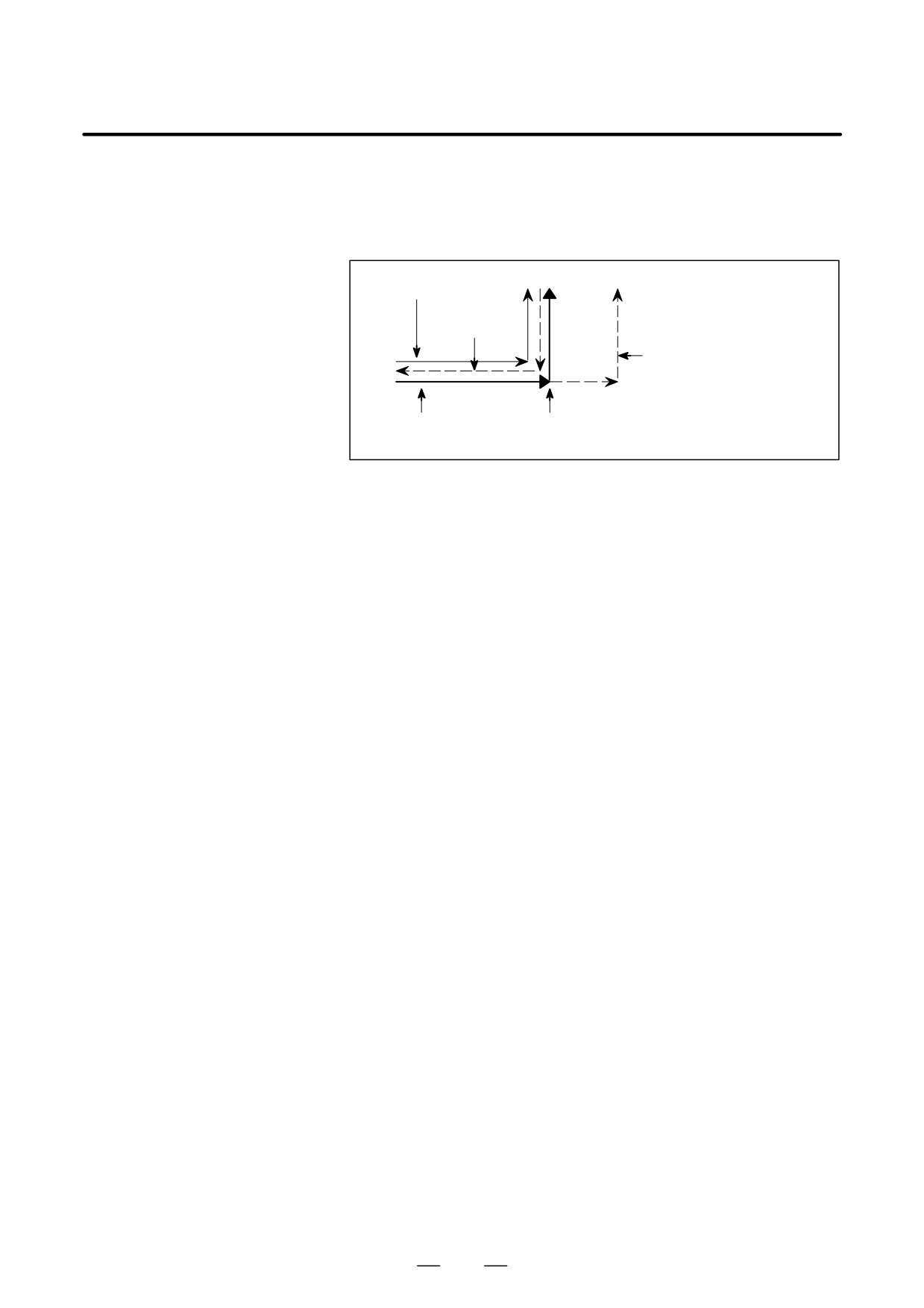
D Skip funtion (G31),
In reverse movement and forward return movement, the skip signal and
automatic tool length
automatic tool length measurement signal are ignored. In reverse
measurement (G37)
movement and forward return movement, the tool moves along the path
actually followed in forward movement.
Forward return
movement
Reverse
movement
When the signal is not applied
(G31) (Programmed path)
Forward movement
Skip signal on (G31) or automatic tool
(actual path)
length measurement signal on (G37)
D Chopping function
Whether the chopping operation is performed in reverse movement and
(G81.1)
forward return movement is determined by whether the chopping
operation was performed at the end of forward movement.
If the tool starts reverse movement with the chopping mode off and moves
in the reverse direction along the path of a block where the chopping mode
is on, the chopping axis maintains its position at point R.
When a block specifying G81.1 (chopping command) appears during
reverse movement, reverse movement ends and operation stops.
Along the path of a block where the tool moved according to inverse time
D Inverse time feed (G93)
feed in forward movement, the tool moves in the reverse direction
according to the feedrate specified by parameter No. 1414 (= 0) for reverse
movement.
If parameter No. 1414 for specifying the feedrate for reverse movement
is not set (= 0), the tool moves in the reverse direction at the same feedrate
as during forward movement.
D Constant surface speed
If the on/off mode of constant surface speed control is specified in reverse
control on/off (G96,G97)
movement, the specified mode is used in subsequent reverse movement.
In other words, when a block specifying G96Sxxxx; appears in reverse
movement, constant surface speed control is on for subsequent reverse
movement. When a block specifying G97Sxxxx; appears in reverse
movement, constant surface speed control is off for subsequent reverse
movement.
Note that the on/off mode of constant surface speed control in forward
movement is reversed in reverse movement.
D Clamping maximum
If the command for clamping maximum spindle speed is specified in
spindle speed
reverse movement, the specified clamp is applied to subsequent reverse
(G92Sxxxx)
movement. In other words, when G92Sxxxx appears in reverse
movement, the spindle speed is clamped at Sxxxx. Note, however, that
the spindle speed is clamped only when the G96 mode is set.
833
OPERATION
4. AUTOMATIC OPERATION
B-63534EN/02
D Auxiliary function
The M, S, and T functions, and secondary auxiliary functions (B
functions) are output directly in reverse movement and forward return
movement.
When an M, S, or T function, or secondary auxiliary function (B function)
is specified in a block containing a move command, the function and the
move command are output at the same time in forward movement, reverse
movement, and forward return movement. This means that the position
where an M, S, or T function, or secondary auxiliary function (B function)
is output differs in forward movement, reverse movement, and forward
return movement.
Even if a cutter compensation value or tool length compensation value is
D Tool compensation value
modified in reverse movement or forward return movement, the tool
moves according to the compensation value used when the block was
executed in the forward movement.
D Custom macro operation
All custom macro operations are ignored in reverse movement and
forward return movement.
The values of macro variables present at the end of forward movement
remain unchanged.
D Manual intervention
When the tool has been moved by manual intervention, return the tool to
the original position before moving the tool in the reverse direction after
a feed hold stop or single block stop.In reverse movement, the tool cannot
move along the path made during manual intervention. All movements
made by manual intervention are ignored in reverse movement and
forward return movement.
D Tool withdrawal and
The tool cannot move along the path retraction or repositioning
return function
performed using the tool withdrawal and return function. All retraction
and repositioning operations are ignored in reverse movement and
forward return movement.
D Mirror image
When a block with the mirror image function specified by a signal or
setting is memorized in forward movement, the mirror image function is
eliminated; the block is memorized as originally programmed.
Accordingly, in reverse movement and forward return movement, the tool
moves along the programmed path.In reverse movement or forward
return movement, the mirror image function can be specified by a signal
or setting.
When the tool performs reverse movement or forward return movement
for a block where the mirror image function is specified by the
programmable mirror image code (G51.1), the tool moves along the
actual path incorporating the mirror image function.
834
OPERATION
B-63534EN/02
4. AUTOMATIC OPERATION
In cases such as when tool movement along an axis is stopped by feed hold
4.12
during automatic operation so that manual intervention can be used to
MANUAL
replace the tool: When automatic operation is restarted, this function
INTERVENTION AND
returns the tool to the position where manual intervention was started.
To use the conventional program restart function and tool withdrawal and
RETURN
return function, the switches on the operator’s panel must be used in
conjunction with the MDI keys. This function does not require such
operations.
Before this function can be used, MIN (bit 0 of parameter No. 7001) must
be set to 1.
Explanations
D Manual absolute on/off
In manual absolute off mode, the tool does not return to the stop position,
but instead operates according to the manual absolute on/off function.
D Override
For the return operation, the dry run feedrate is used, and the jog feedrate
override function is enabled.
D Return operation
Return operation is performed according to positioning based on
nonlinear interpolation.
D Single block
If the single block stop switch is on during return operation, the tool stops
at the stop position and restarts movement when the cycle start switch is
pressed.
D Cancellation
If a reset occurs or an alarm is issued during manual intervention or the
return operation, this function is cancelled.
D MDI mode
This function can be used in the MDI mode as well.
Limitations
D Enabling and disabling
This function is enabled only when the automatic operation hold LED is
manual intervention and
on. When there is no travel distance remaining, this function has no effect
return
even if a feed hold stop is performed with the automatic operation hold
signal *SP (bit 5 of G008).
D Offset
When the tool is replaced using manual intervention for a reason such as
damage, the tool movement cannot be restarted by a changed offset in the
middle of the interrupted block.
D Machine lock, mirror
When performing manual intervention, never use the machine lock,
image, and scaling
mirror image, or scaling functions.
835
OPERATION
4. AUTOMATIC OPERATION
B-63534EN/02
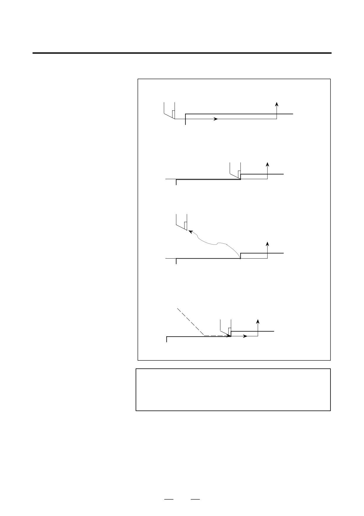
Example
1. The N1 block cuts a workpiece
Tool
N2
Block start point
N1
2. The tool is stopped by pressing the feed hold switch in
the middle of the N1 block (point A).
N2
N1 Point A
3. After retracting the tool manually to point B, tool movement is restarted.
Point B
Manual
intervention
N2
N1 Point A
4. After automatic return to point A at the dry run feedrate, the remaining
move command of the N1 block is executed.
B
N2
N1 Point A
WARNING
When performing manual intervention, pay particular
attention of machining and the shape of the workpiece so
that the machine and tool are not damaged.
836
OPERATION
B-63534EN/02
4. AUTOMATIC OPERATION
4.13
DNC OPERATION
WITH MEMORY
CARD
4.13.1
“DNC operation with Memory Card” is a function that it is possible to
perform machining with executing the program in the memory card,
Specification
which is assembled to the memory card interface, where is the left side
of the screen.
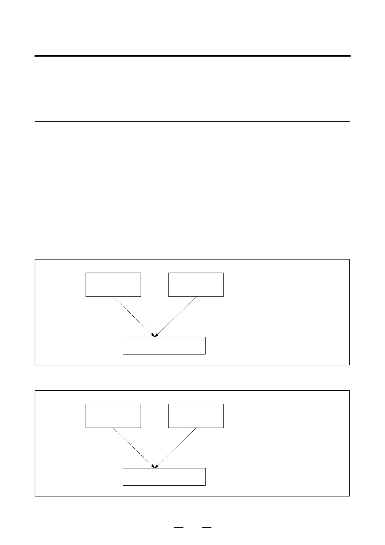
There are two methods to use this function as follows.
(a) By starting automatic operation
(cycle start) during the DNC
operation mode (RMT), it is possible to perform machining (DNC
operation) while a program is being read from a memory card, as by
using the external input/output unit such as a floppy cassette and so on.
(Fig. 4.13.1 (a))
(b) It is possible to read sub-programs written in the memory card and
execute them by the command Subprogram call (M198). (Fig. 4.13.1
(b))
It is possible to do the DNC
Memory in CNC
Memory Card
operation with Memory card
(Program)
(Program)
instead of the normal memory
operation by memory in the CNC.
Normal Memory
DNC operation
operation by
with Memory
memory in the
card
CNC
Execution of programs
Fig. 4.13.1 (a)
It is possible to execute the
Memory in CNC
Memory Card
subprogram in the memory card
(Program)
(Sub Program)
during memory operation.
Normal Memory
Subprogram
operation by memory
Call (M198)
in the CNC
Execution of programs
Fig. 4.13.1 (b)
837
OPERATION
4. AUTOMATIC OPERATION
B-63534EN/02
NOTE
1
To use this function, it is necessary to set the parameter of
No.20 to 4 by setting screen.
No.20 [I/O CHANEL: Setting to select an input/output unit]
Setting value is
4.: It means using the memory card
interface.
2
When CNC control unit is a stand-alone type, the memory
card interface on the left side of the screen of the display unit
is available. But the interface on the control unit is not
available.
4.13.2
Operations
4.13.2.1
DNC Operation
Procedure
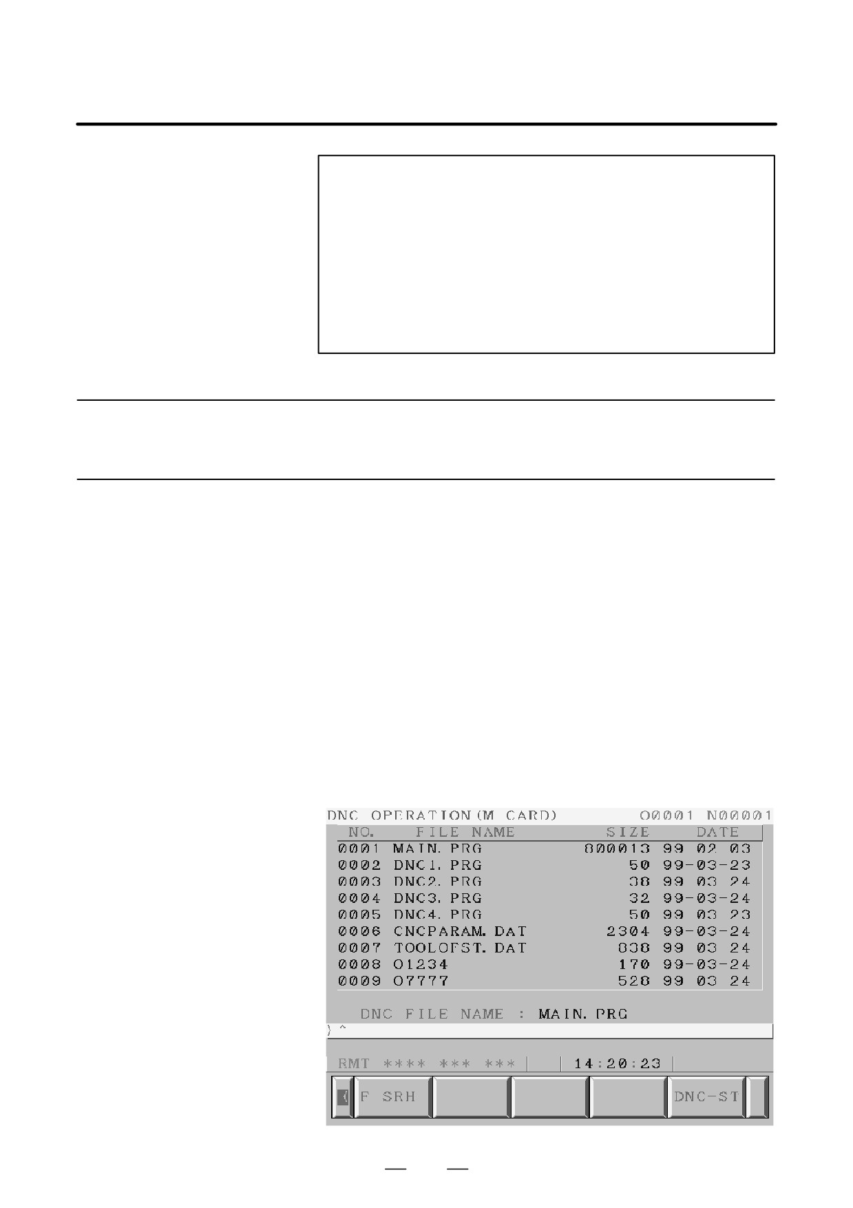
Please set the parameter of No.0020 to 4 in the setting screen in advance.
(1) Change to RMT mode.
(2) Push [PROGRAM] function key.
(3) Push [ > ] soft key (continuance menu).
(4) When [DNC-CD] soft key is pushed, the following screen is
displayed.
(5) The screen can be scrolled by page key. An arbitrary file number is
input, and [F SRH] soft key is pushed. Then the arbitrary file name
is displayed at the top of DNC operation (memory card) screen.
(6) When the file number that is executed is input and the [DNC-ST] soft
key is pushed, the file name that is selected is set to DNC FILE.
(7) When the cycle start is done, the program that is selected is executed.
838
OPERATION
B-63534EN/02
4. AUTOMATIC OPERATION
4.13.2.2
When the following block in a program in CNC memory is executed, a
subprogram file in memory card is called.
Subprogram Call (M198)
Format
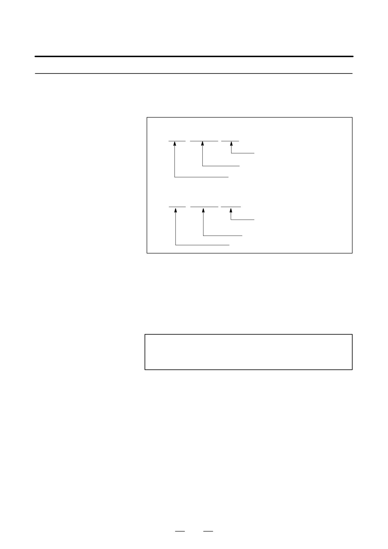
1. Normal format
M198 Pffff ∆∆∆∆ ;
File number for a file in
the memory card
Number of repetition
Memory card call instruction
2. FS15 tape format
M198 Pffff L∆∆∆∆ ;
File number of repetition
File number for a file in the
memory card
Memory card call instruction
Explanation
When the custom macro option is provided, both format 1 and 2 can be
used. A different M code can be used for a subprogram call depending
on the setting of parameter No. 6030. In this case, M198 is executed as
a normal M code. The file number is specified at address P. If the SBP
(bit 2) of parameter No. 3404 is set to 1, a program number can be
specified. When a file number is specified at address P, Fxxxx is indicated
instead of Oxxxx.
NOTE
Please set the parameter of No. 0020 to 4 in the setting
screen in advance.
839
OPERATION
4. AUTOMATIC OPERATION
B-63534EN/02
4.13.3
(1) The memory card can not be accessed, such as display of memory card
list and so on, during the DNC operation with memory card.
Limitation and Notes
(2) It is possible to execute the DNC operation with memory card on multi
path system. However, it is not possible to call programs from the
plural paths at the same time.
(3) The selection of DNC operation file that is set at DNC OPERATION
screen is cleared by the power supply turn off and on. After the power
supply is turned on again, it is necessary to select the DNC operation
file again.
(4) Please do not pull out and insert memory card during the DNC
operation with memory card.
(5) It is not possible to call a program in the memory card from the DNC
operation program.
(6) In case of using this function, the PMCIA card attachment written at
section 6 must be used to prevent a poor connection or drop out of the
memory card from occurring by vibration of the machine.
(7) In case of the stand-alone type i series that the display unit is a Display
link unit, this function can not be used.
(8) The memory card interface on the stand-alone type controller is not
available. Please use the memory card interface on the display unit.
4.13.4
#7
#6
#5
#4
#3
#2
#1
#0
Parameter
0138
DNM
[Data type] Bit
#7 (DNM) The DNC operation with memory card function is
0 : disable.
1 : enable.
840
OPERATION
B-63534EN/02
4. AUTOMATIC OPERATION
4.13.5
Connecting PCMCIA
Card Attachment
4.13.5.1
Specification Number
Specification
Remarks
A02B-0236-K160
For 7.2″ LCD or 8.4″ LCD
A02B-0236-K161
For 9.5″ LCD or 10.4″ LCD
4.13.5.2
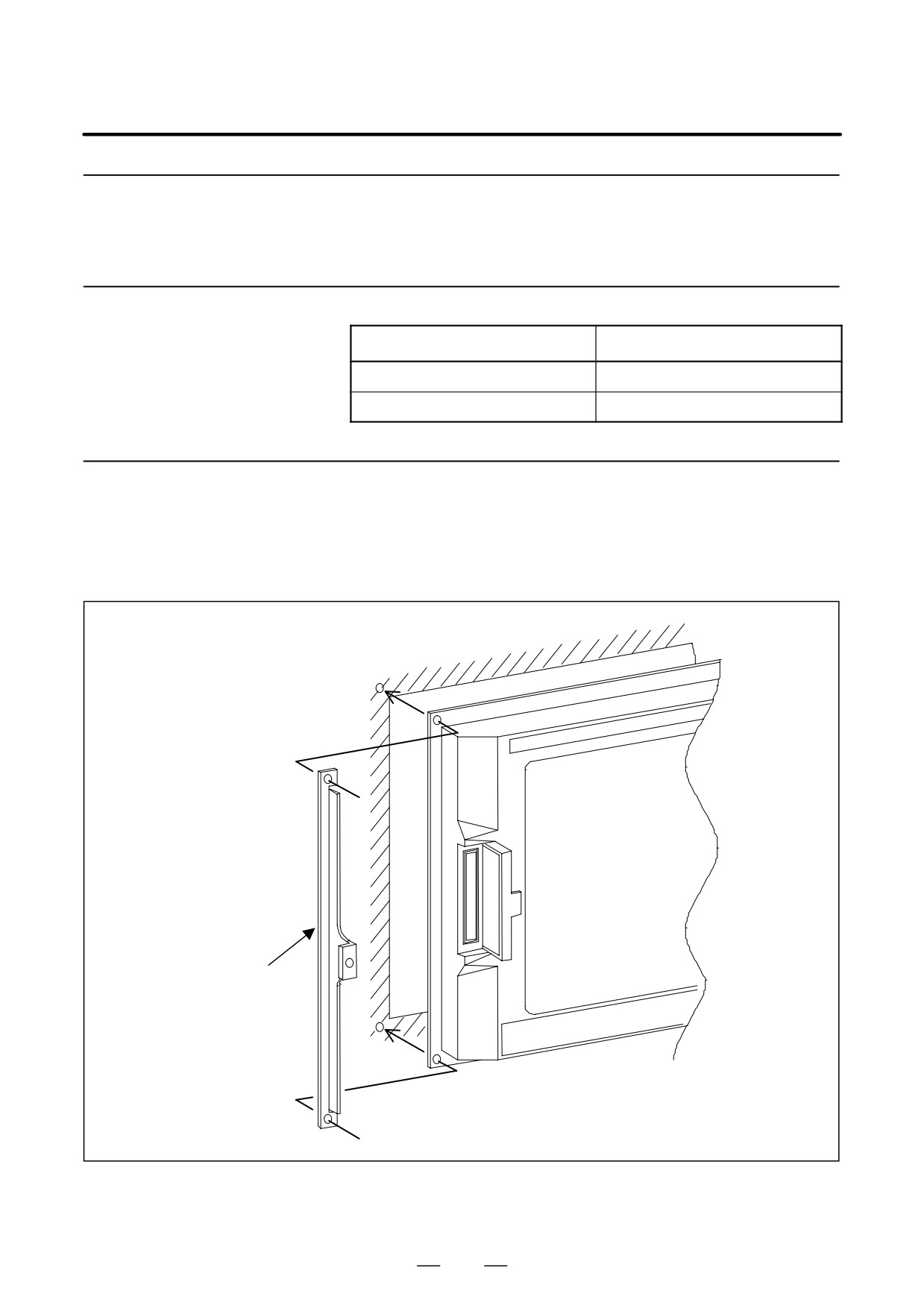
1) How to assemble to the unit
Assemble an attachment guide and a control unit to the cabinet by
Assembling
screwing together as follow figure.
The attachment guide is 1.6mm thick. Pay attention for the length of
the screws when you assemble them.
Attachment guide
841
OPERATION
4. AUTOMATIC OPERATION
B-63534EN/02
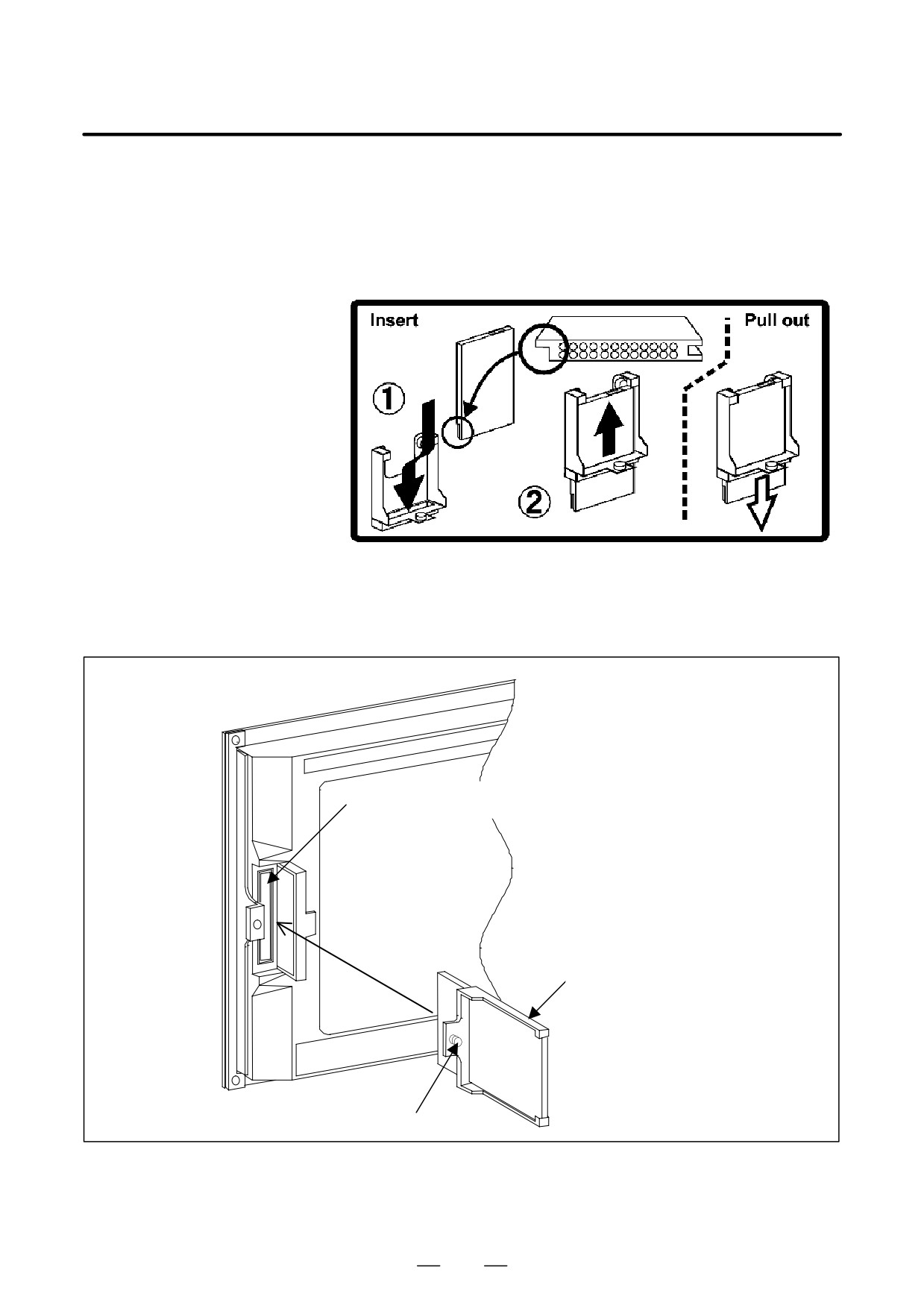
2) How to mount the card
(a) Insert the card to slit of the attachment. Please pay attention to the
direction of the card.
(Please mach the direction of ditch on the
card.)
(b) Push up the card to the upper end of the attachment.
3) Assembling of the attachment
Insert the memory card with the attachment into the memory card
interface as following figure. And, fix the attachment guide by
screwing the screw of the attachment guide by manual.
Memory card interface
attachment
screw to fix the attachment
842
OPERATION
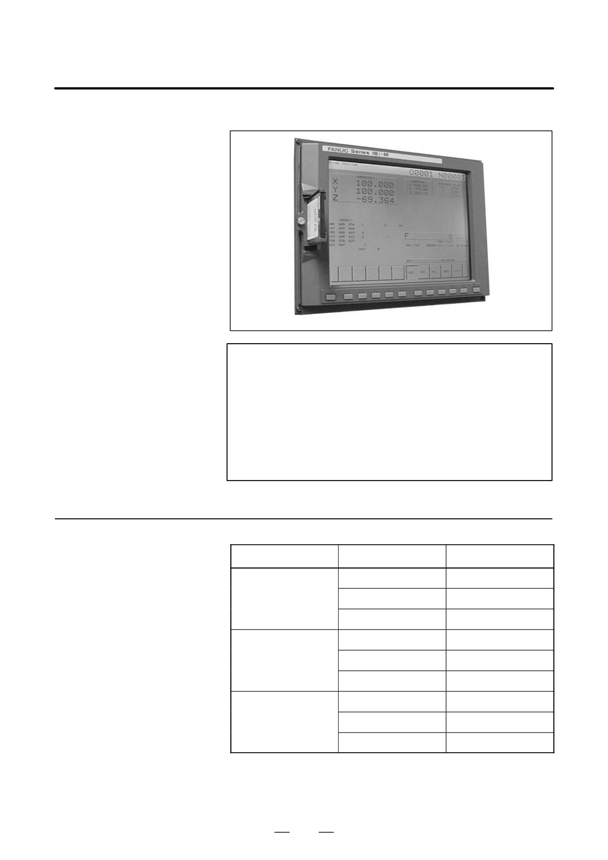
B-63534EN/02
4. AUTOMATIC OPERATION
4) Appearance after connection
NOTE
1
In both case of stand-alone type i series and LCD-mounted
type i series, the memory card interface where is the left side
of the screen of the display unit. (The memory card interface
on the stand-alone type controller is not available.)
2
It is impossible to assemble the display unit and the
attachment guide from inside of the cabinet.
3
The memory card must be used in the condition, as the
coolant cannot be poured directly on it.
4.13.6
Recommended
Maker
Type
Capacity
Memory Card
Hitachi LTD
HB289016A4
16MB
HB289032A4
32MB
HB289160A4
160MB
Matushita electric
BN-012AB
12MB
BN-020AB
20MB
BN-040AB
40MB
SanDisk
SDP3B-4
4MB
SDP3B-20
20MB
SDP3B-40
40MB
843
5. TEST OPERATION
OPERATION
B-63534EN/02
TEST OPERATION
5
The following functions are used to check before actual machining
whether the machine operates as specified by the created program.
5.1
Machine Lock and Auxiliary Function Lock
5.2
Feedrate Override
5.3
Rapid Traverse Override
5.4
Dry Run
5.5
Single Block
844
B-63534EN/02
OPERATION
5. TEST OPERATION
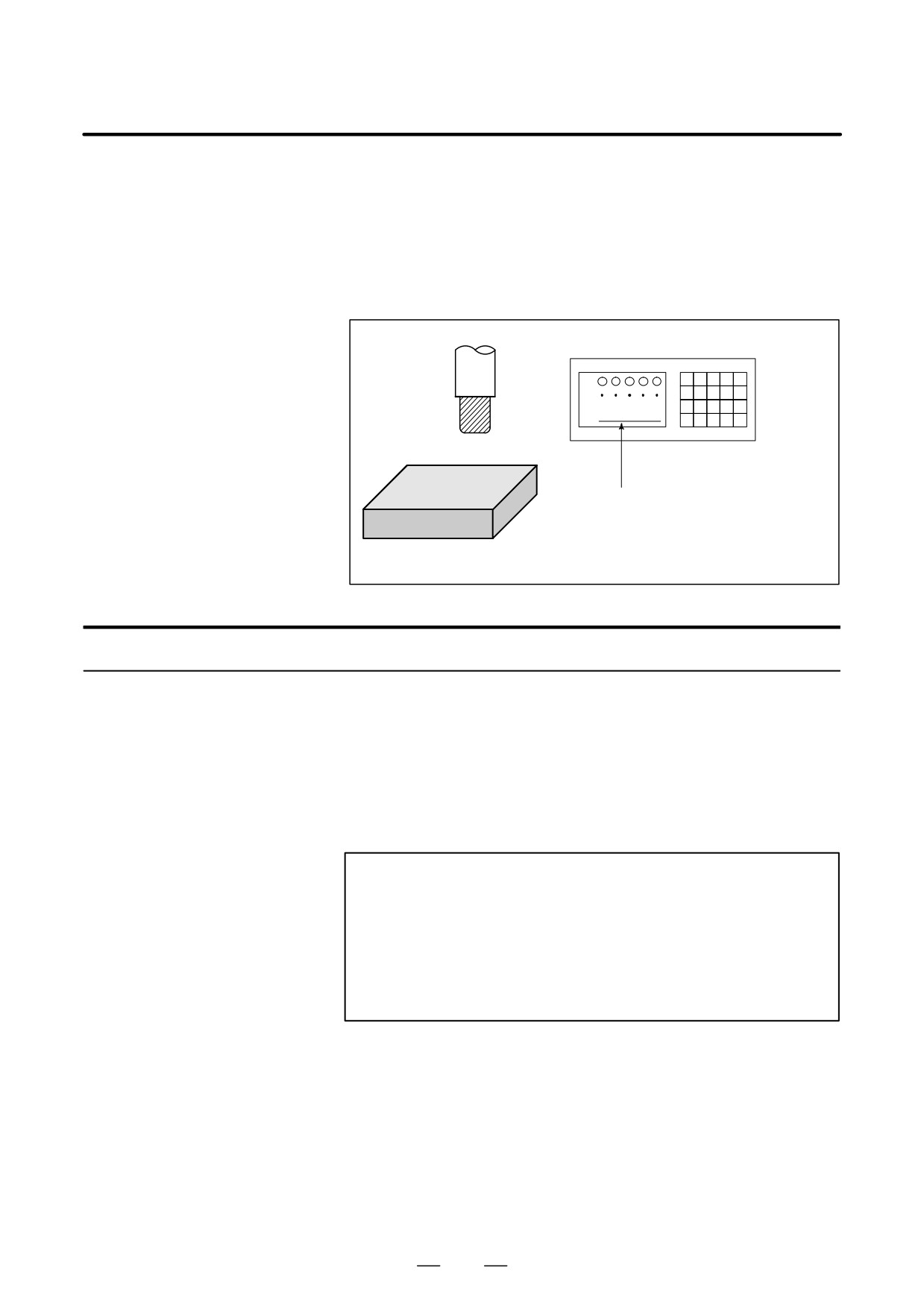
To display the change in the position without moving the tool, use
5.1
machine lock.
MACHINE LOCK AND
There are two types of machine lock: all-axis machine lock, which stops
AUXILIARY
the movement along all axes, and specified-axis machine lock, which
stops the movement along specified axes only. In addition, auxiliary
FUNCTION LOCK
function lock, which disables M, S, and T commands, is available for
checking a program together with machine lock.
MDI
X
Y
Tool
Z
Workpiece
The tool does not move but the
position along each axis changes
on the display.
Fig. 5.1 Machine lock
Procedure for Machine Lock and Auxiliary Function Lock
D Machine Lock
Press the machine lock switch on the operator’s panel. The tool does not
move but the position along each axis changes on the display as if the tool
were moving.
Some machines have a machine lock switch for each axis. On such
machines, press the machine lock switches for the axes along which the
tool is to be stopped. Refer to the appropriate manual provided by the
machine tool builder for machine lock.
WARNING
The positional relationship between the workpiece
coordinates and machine coordinates may differ before and
after automatic operation using machine lock. In such a
case, specify the workpiece coordinate system by using a
coordinate setting command or by performing manual
reference position return.
D Auxiliary Function Lock
Press the auxiliary function lock switch on the operator’s panel. M, S, T
and B codes are disabled and not executed. Refer to the appropriate
manual provided by the machine tool builder for auxiliary function lock.
845
5. TEST OPERATION
OPERATION
B-63534EN/02
Restrictions
D M, S, T, B command by
M, S, T and B commands are executed in the machine lock state.
only machine lock
D Reference position
When a G27, G28, or G30 command is issued in the machine lock state,
return under Machine
the command is accepted but the tool does not move to the reference
Lock
position and the reference position return LED does not go on.
D M codes not locked by
M00, M01, M02, M30, M98, and M99 commands are executed even in
auxiliary function lock
the auxiliary function lock state. M codes for calling a subprogram
(parameters No. 6071 to 6079) and those for calling a custom macro
(parameter No. 6080 to 6089) are also executed.
846
B-63534EN/02
OPERATION
5. TEST OPERATION
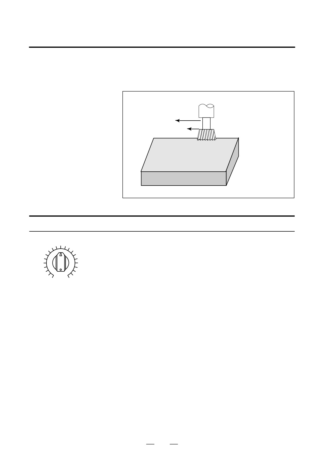
A programmed feedrate can be reduced or increased by a percentage (%)
5.2
selected by the override dial.This feature is used to check a program.
FEEDRATE
For example, when a feedrate of 100 mm/min is specified in the program,
OVERRIDE
setting the override dial to 50% moves the tool at 50 mm/min.
Feedrate 100 mm/min
Tool
(Specified by programmed)
Check the machining
by altering the feedrate
Feedrate 50 mm/min after
from the value speci-
feedrate override
fied in the program.
Workpiece
Fig. 5.2 Feedrate override
Procedure for Feedrate Override
Set the feedrate override dial to the desired percentage (%) on the machine
operator’s panel, before or during automatic operation.
On some machines, the same dial is used for the feedrate override dial and
jog feedrate dial. Refer to the appropriate manual provided by the
machine tool builder for feedrate override.
0
200
JOG FEED RATE OVERRIDE
Restrictions
D Override Range
The override that can be specified ranges from 0 to 254%. For individual
machines, the range depends on the specifications of the machine tool
builder.
D Override during thread
During threading, the override is ignored and the feedrate remains as
specified by program.
847
5. TEST OPERATION
OPERATION
B-63534EN/02
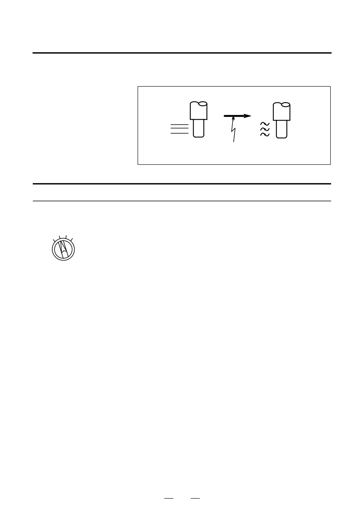
An override of four steps (F0, 25%, 50%, and 100%) can be applied to the
5.3
rapid traverse rate. F0 is set by a parameter (No. 1421).
RAPID TRAVERSE
OVERRIDE
ÇÇ
ÇÇ
ÇÇ
ÇÇ
ÇÇ
ÇÇ
Rapid traverse Override
5m/min
rate10m/min
50%
Fig. 5.3 Rapid traverse override
Rapid Traverse Override
Procedure
Select one of the four feedrates with the rapid traverse override switch
during rapid traverse. Refer to the appropriate manual provided by the
25
50
machine tool builder for rapid traverse override.
LOW
100
Rapid traverse override
Explanation
The following types of rapid traverse are available. Rapid traverse
override can be applied for each of them.
1) Rapid traverse by G00
2) Rapid traverse during a canned cycle
3) Rapid traverse in G27, G28, G29, G30, G53
4) Manual rapid traverse
5) Rapid traverse of manual reference position return
848
B-63534EN/02
OPERATION
5. TEST OPERATION
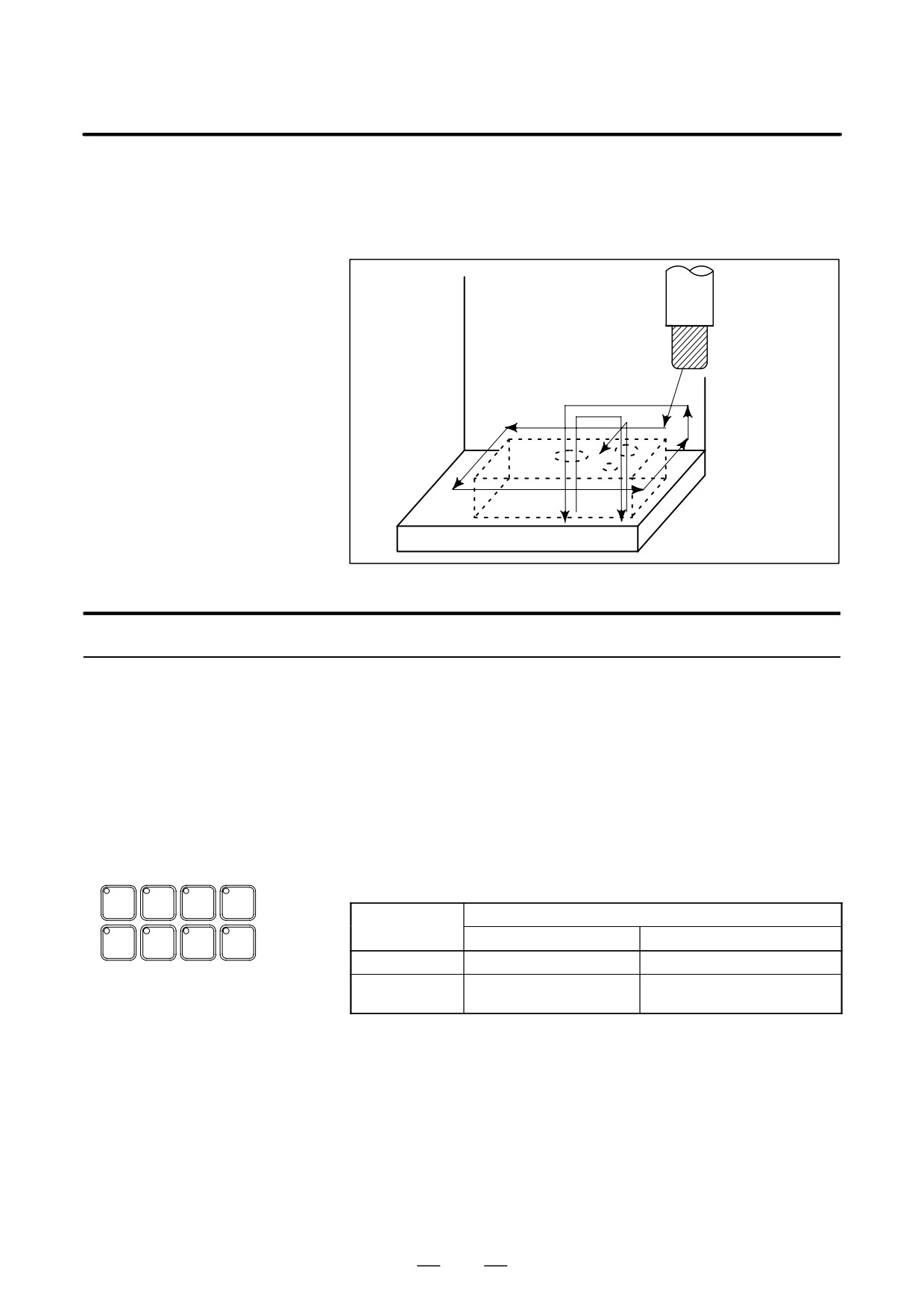
The tool is moved at the feedrate specified by a parameter regardless of
5.4
the feedrate specified in the program. This function is used for checking
DRY RUN
the movement of the tool under the state taht the workpiece is removed
from the table.
Tool
Table
Fig. 5.4 Dry run
Procedure for Dry Run
Procedure
Press the dry run switch on the machine operator’s panel during automatic
operation.
The tool moves at the feedrate specified in a parameter. The rapid traverse
switch can also be used for changing the feedrate.
Refer to the appropriate manual provided by the machine tool builder for
dry run.
Explanation
D Dry run feedrate
The dry run feedrate changes as shown in the table below according to the
rapid traverse switch and parameters.
SINGLE
OPT
BLOCK
MC
BLOCK
STOP
SKIP
LOCK
Program command
Rapid traverse
button
Rapid traverse
Feed
DRY
MST
WORK
RUN
LOCK
LIGHT
ON
Rapid traverse rate
Dry run feedrate Max.JV *2)
OFF
Dry run speed JV,or
Dry run feedrate JV
rapid traverse rate *1)
*2)
Max. cutting feedrate
Setting by parameter No.1422
Rapid traverse rate
Setting by parameter No.1420
Dry run feedrate
Setting by parameter No.1410
JV: Jog feedrate override
*1) Dry run feedrate x JV when parameter RDR (bit 6 of No. 1401) is
1. Rapid traverse rate when parameter RDR is 0.
*2) Clamped to the maximum cutting feedrate
JVmax: Maximum value of jog feedrate override
849