FANUC Series 16i/160i/160is-MB, Series 18i/180i/180is-MB5, Series 18i/180i/180is-MB. Operator's Manual - page 21
20. AXIS CONTROL FUNCTIONS
PROGRAMMING
B-63534EN/02
Compensation angle +Z Q sin(P)
360 (In inch input)
p T
Where,
Compensation angle : Absolute value with sign (degrees)
Z
: Amount of travel along the Z axis after a
G81 command is issued (mm or inch)
P
: Twisted angle of the gear with sign (degrees)
p
: Ratio of the circumference of a circle to its
diameter
T
: Number of teeth
Q
: Module (mm) or diametral pitch (1/inch)
Use P, T, and Q specified in the G81 block.
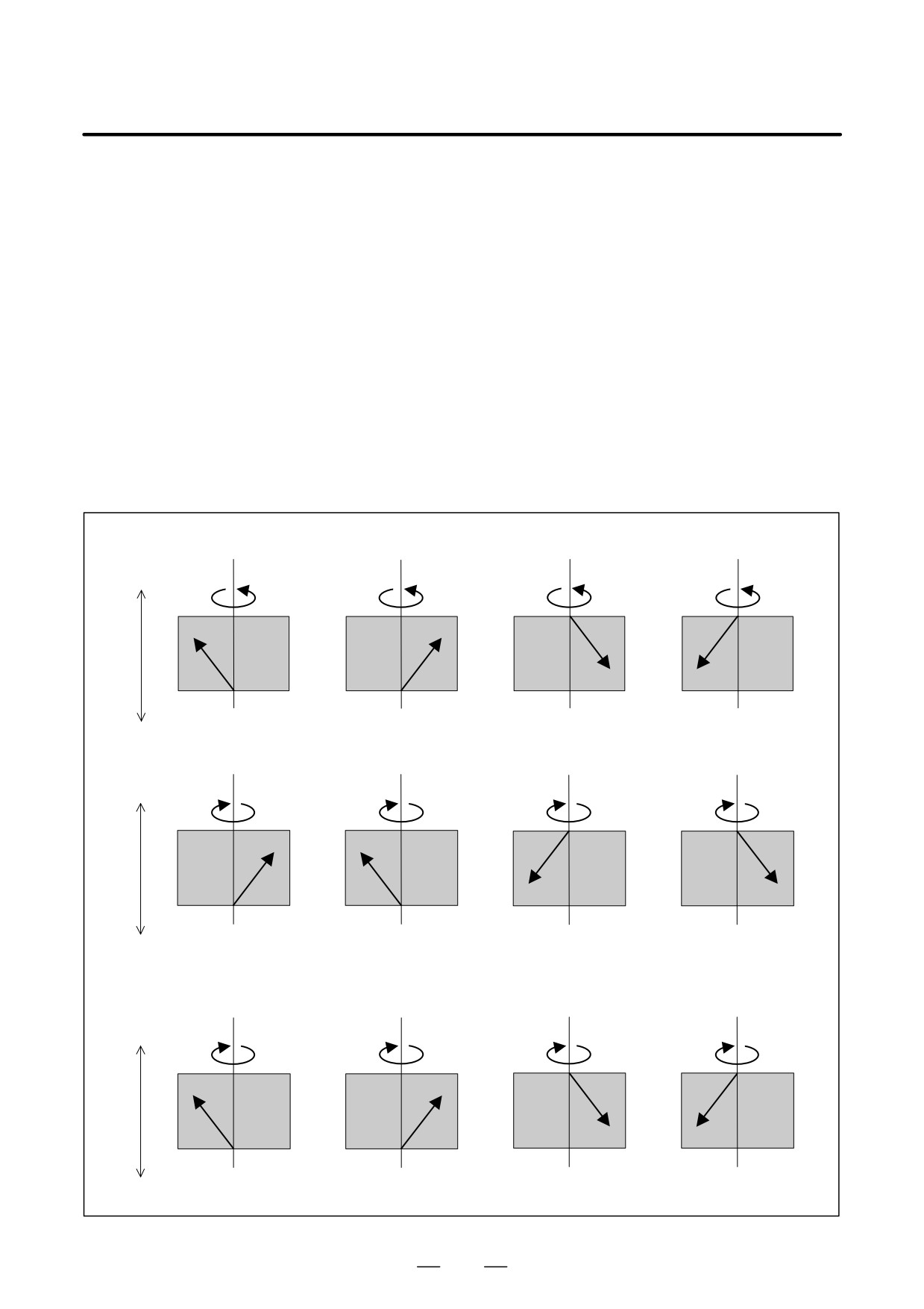
D Compensation direction
Parameter HDR (bit 2 of No. 7700)
in helical gear
compensation
When the HDR bit is set to 1
(a)
(b)
(c)
(d)
+Z
+C
+C
+C
+C
C : +, Z : +, P : +
C : +, Z : +, P : +
C : +, Z : -, P : +
C : +, Z : -, P : -
Compensation direction : +
Compensation direction : -
Compensation direction : -
Compensation direction : +
-Z
(e)
(f)
(g)
(h)
+Z
-C
–C
-C
-C
C : -, Z : +, P : +
C : -, Z : +, P : -
C : -, Z : -, P : +
C : -, Z : -, P : -
Compensation direction : -
Compensation direction : + Compensation direction : +
Compensation direction : -
-Z
When the HDR bit is set to 0 ((a), (b), (c), and (d) are the same as when the HDR bit is set to 1)
(e)
(f)
(g)
(h)
+Z
-C
–C
-C
-C
C : -, Z : +, P : +
C : -, Z : +, P : -
C : -, Z : -, P : -
C : -, Z : -, P : -
Compensation direction : +
Compensation direction : + Compensation direction : -
Compensation direction : +
-Z
580
B-63534EN/02
PROGRAMMING
20. AXIS CONTROL FUNCTIONS
Examples
(1) When the master axis is the spindle, and the slave axis is the C-axis
1. G81.5 T10 C0 L1 ;
Synchronization between the master axis and C-axis is started at
the ratio of one rotation about the C-axis to ten rotations about the
master axis.
2. G81.5 T10 C0 L-1 ;
Synchronization between the master axis and C-axis is started at
the ratio of one rotation about the C-axis to ten rotations about the
master axis.
In this case, however, the direction of rotation is opposite to that of
1. above.
3. G81.5 T1 C3.26 ;
Synchronization between the master axis and C-axis is started at
the ratio of a 3.26-degree rotation about the C-axis per one rotation
about the master axis.
4. G81.5 P10000 C-0.214 ;
Synchronization between the master axis and C-axis is started at
the ratio of a -0.214 degree rotation about the C-axis to 10,000
feedback pulses from the pulse coder of the master axis.
(2) When the master axis is the spindle, the slave axis is the V-axis (linear
axis), and inch/metric conversion is performed
1. For a millimeter machine and metric input
G81.5 T1 V1.0 ;
Synchronization between the master axis and V-axis is started at
the ratio of a 1.00 mm movement along the V-axis per rotation
about the master axis.
2. For a millimeter machine and inch input
G81.5 T1 V1.0 ;
Synchronization between the master axis and V-axis is started at
the ratio of a 1.0 inch movement (25.4 mm) along the V-axis per
rotation about the master axis.
(3) When two groups of axes are synchronized simultaneously
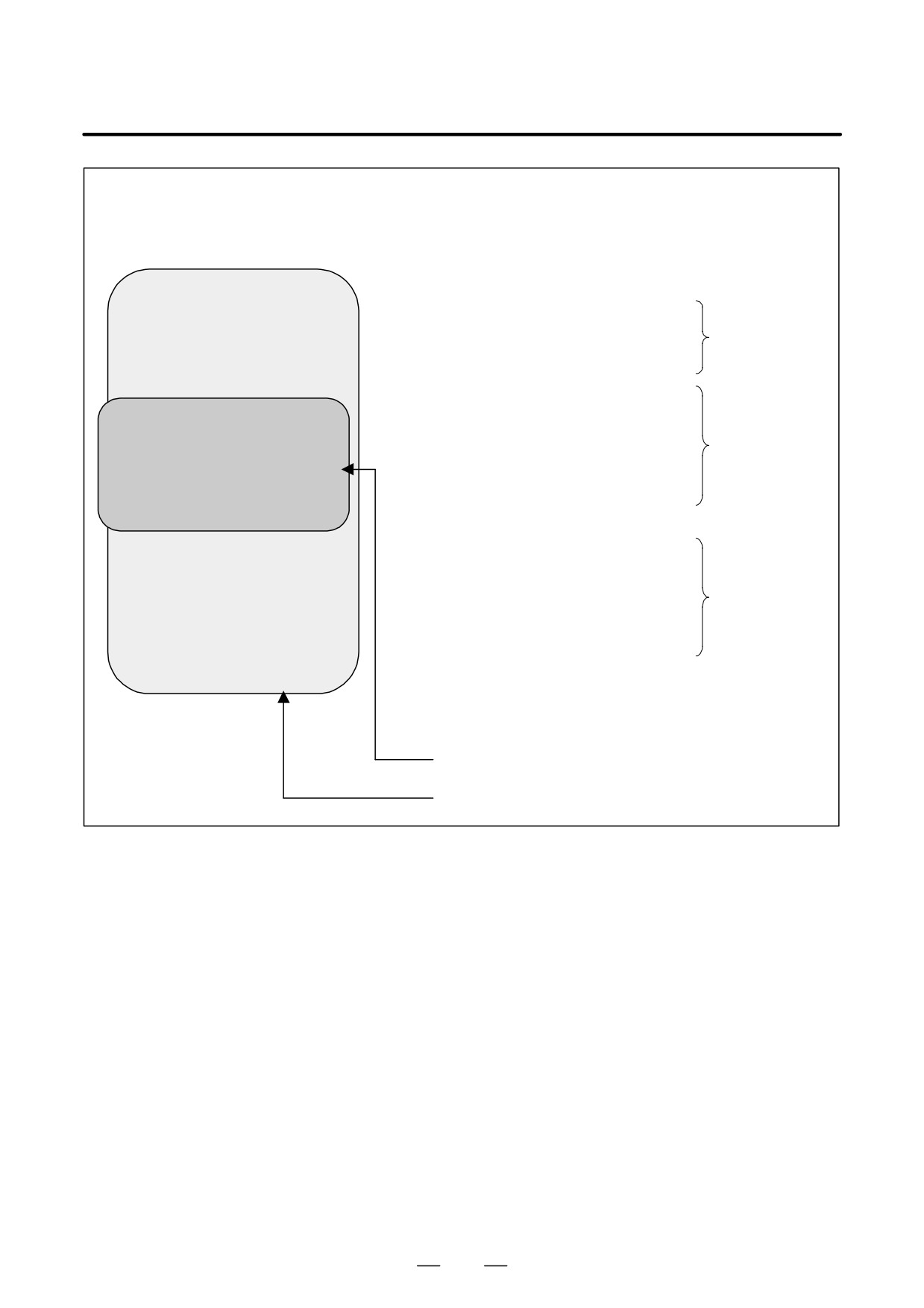
Based on the controlled axis configuration described in Fig.20.8.5,
the sample program below synchronizes the spindle with the V-axis
while the spindle is synchronized with the C-axis.
581
20. AXIS CONTROL FUNCTIONS
PROGRAMMING
B-63534EN/02
O0100 ;
N01 Mxx ;
Performs spindle orientation.
N02 G00 G90 C... ;
Positions the C-axis.
Starts synchronization at the ratio of
N03 G81.5 T10 C0 L1 ;
one rotation about the C-axis to ten
spindle rotations.
N04 Myy S300
Rotates the spindle.
N05 G01 G91 X... Y... F... ;
Makes movements for grinding.
Grinding
N06 Mzz ;
Stops the spindle.
N10 G00 G90 V... ;
Positions the dressing axis.
N11 G81.5 P12000 V0.5 ;
Starts synchronization at the ratio of a
0.5 mm movement along the V-axis
Dressing
every 12,000 pulses on the spindle.
N12 Myy S300
N20 M98 P9500 ;
Rotates the spindle.
A subprogram for dressing is called.
N21 Mzz ;
Stops the spindle.
N30 G80.5 V0 ;
Cancels V-axis synchronization.
Grinding
N31 Myy S300 ;
Rotates the spindle
N32 G01 G91 X... Y... F... ;
Makes movements for grinding
N40 Mzz ;
Stops the spindle.
N41 G80.5 C0 ;
Cancels C-axis synchronization.
V-axis synchronization mode
C-axis synchronization mode
Thus, the synchronizations of two groups can be started and canceled
independently of each other.
(4)
Command specification for hobbing machines
Based on the controlled axis configuration described in Fig.20.8.5,
the sample program below sets the C-axis (in parameter 7710) for
starting synchronization with the spindle according to the command
specification method for hobbing machines.
582
B-63534EN/02
PROGRAMMING
20. AXIS CONTROL FUNCTIONS
O1234 ;
N01 G81 T20 L1 ; Starts synchronization with the spindle and
C-axis at the ratio of a 1/20 rotation about the
C-axis to one spindle rotation.
N02 Mxx S300 ; Rotates the spindle at 300 min-1.
N03 X... F... ;
Makes a movement along the X-axis (for
cutting).
N04 Y... F... ;
Makes a movement along the Y-axis (for
grinding). Axes such as the C-axis, X-axis,
and Y-axis can be specified as required.
N05 X... F... ;
Makes a movement along the X-axis (for
retraction).
N06 Mzz ;
Stops the spindle.
N07 G80 ;
Cancels the synchronization between the
spindle and C-axis.
D Synchronization Ratio
The programmed ratio (synchronization ratio) of a movement along the
Specification Range
slave axis to a movement along the master axis is converted to a detection
unit ratio inside the NC. If such converted data (detection unit ratio)
exceeds a certain allowable data range in the NC, synchronization cannot
be established correctly, and an alarm (P/S 181) is issued.
Even when a programmed master axis movement and a programmed
slave axis movement are within specifiable ranges, a detection unit ratio
obtained by conversion can exceed the allowable range, thus resulting in
an alarm.
Let K be a synchronization ratio. The internal data corresponding K is the
amount of slave axis movement (Kn) represented in the detection unit
divided by the amount of master axis movement (Kd) represented in the
detection unit; this fraction is represented as Kn/Kd (reduced to its lowest
terms) as indicated below.
Kn
mount of slave axis movement represented in the detection unit
K+
Kd+Amount of master axis movement represented in the detection unit
Kn and Kd must lie within the following ranges:
-2147483648
v Kn v 2147483647
1
v Kd v 65535
When Kn or Kd exceeds its allowable range above, an alarm is issued.
In conversion to the detection unit, when the CMR
(command
multiplication: parameter 1820) is a fraction or when inch/millimeter
conversion is used, the fraction is directly converted without modification
so that no error can occur in the conversion of specified amounts of
movement.
During conversion, the amount of movement is multiplied by 254/100 for
inch input on a millimeter machine, and 100/254 for metric input on an
inch machine. Thus, Kn and Kd can become large numbers. If a
synchronization ratio cannot be reduced to its lowest terms, an alarm
condition is likely to occur.
583
20. AXIS CONTROL FUNCTIONS
PROGRAMMING
B-63534EN/02
D Example 1)
Based on the controlled axis configuration described in Fig.20.8.5,
suppose that the spindle and V-axis are as follows:
Spindle pulse coder
:
72000pulse/rev (4 pulses for
one A/B phase cycle)
C-axis least command increment : 0.001 degree
C-axis CMR
:
5
V-axis least command increment : 0.001mm
V-axis CMR
:
5
Then, the C-axis detection unit is 0.0002 degree. The V-axis detection
unit is 0.0002 mm. In this case, the synchronization ratio (Kn, Kd) is
related with a command as indicated below. Here, let Pm and Ps be the
amounts of movements represented in the detection unit on the master
axis and slave axis specified in a synchronization start command,
respectively.
(1) When the master axis is the spindle, and the slave axis is the C-axis
(a)
Command : G81.5 T10 C0 L1 ;
Operation
: Synchronization between the spindle and C-axis is
started at the ratio of one rotation about the C-axis
to ten spindle rotations.
Pm
:
(Number of pulses per spindle rotation)
10
rotations → 72000
10
Ps
:
(Amount of movement per rotation about the
C-axis)
CMR
(one rotation) → 360000
5
1
Kn
60000
5
1
5
+
Kd+3
72000
10
2
Both Kn and Kd are within the allowable range. No alarm is output.
(b)
Command : G81.5 T10 C0 L-1 ;
Operation
: Synchronization between the spindle and C-axis is
started at the ratio of one rotation about the C-axis
to ten spindle rotations.
In this case, however, the direction of rotation is
opposite to that of (a) above.
Pm
:
(Number of pulses per spindle rotation)
10
revolutions → 72000
10
Ps
:
(Amount of movement per rotation about the
C-axis)
CMR
(one rotation) → -360000
5
1
Kn
360000
5
1
+*5
Kd+*
72000
10
2
Both Kn and Kd are within the allowable range. No alarm is
output.
(c)
Command : G81.5 T1 C3.263 ;
Operation
: Synchronization between the spindle and C-axis is
started at the ratio of a 3.263-degree rotation about
the C-axis to one spindle rotation.
Pm
:
(Number of pulses per spindle rotation)
1 rotation
→ 72000
1
Ps
:
(Amount of C-axis movement) CMR → 3263
5
Kn
263
5
Kd+73
2000
1
14400
584
B-63534EN/02
PROGRAMMING
20. AXIS CONTROL FUNCTIONS
Both Kn and Kd are within the allowable range. No alarm is
output.
In this sample program, when T1 is specified for the master axis,
the synchronization ratio (fraction) of the CMR of the C-axis to
the denominator Kd can always be reduced to lowest terms, thus
Kd falls in the allowable range. So, the specifiable range of C is
as follows:
-99999999 v C v 99999999
(d)
Command : G81.5 T10 C3.263 ;
Operation
: Synchronization between the spindle and C-axis is
started at the ratio of a 3.263-degree rotation about
the C-axis to ten spindle rotations.
Pm
:
(Number of pulses per spindle rotation)
10
rotations → 72000
10
Ps
:
(Amount of the C-axis movement) CMR →
3263
5
Kn
263
5
263
Kd+72000
10+1
4400
In this case, an alarm is issued because Kd exceeds the specifiable
range.
(e)
Command : G81.5 P10000 C-0.214 ;
Operation
: Synchronization between the spindle and C-axis is
started at the ratio of a -0.214 degree rotation of the
C-axis to 10,000 feedback pulses from the pulse
coder of the spindle.
Pm
:
(Specified number of feedback pulses from the pulse
coder of the spindle) → 10000
Ps
:
(Amount of C-axis movement) CMR → -214
5
Kn
214
5
+*107
Kd+*10000
1000
Both Kn and Kd are within the allowable range. No alarm is
output.
(2) When the master axis is the spindle, the slave axis is the V-axis (linear
axis), and inch/metric conversion is performed
(a) For a millimeter machine and metric input
Command : G81.5 T1 V1.0 ;
Operation
: Synchronization between the spindle and V-axis is
started at the ratio of a 1.00 mm movement along
the V-axis per spindle rotation.
Pm
:
(Number of pulses per spindle rotation)
1
rotation → 72000
1
Ps
:
(Amount of V-axis movement) CMR → 1000
5
Kn
000
5
5
+
Kd+1
72000
72
Both Kn and Kd are within the allowable range. No alarm is
output.
(b) For a millimeter machine and inch input
Command : G81.5 T1 V1.0 ;
Operation
: Synchronization between the spindle and V-axis is
started at the ratio of a 1.0 inch movement (25.4
mm) along the V-axis per spindle rotation.
Pm
:
(Number of pulses per spindle rotation)
1
revolution → 72000
1
585
20. AXIS CONTROL FUNCTIONS
PROGRAMMING
B-63534EN/02
Ps
:
(Amount of V-axis movement) CMR
254 B
100 → 10000
5
254 B 100
Kn
0000
5
254
127
+
Kd+1
72000
100
72
Both Kn and Kd are within the allowable range. No alarm is
output.
(c) For a millimeter machine and inch input
Command : G81.5 T1 V0.0013 ;
Operation
: Synchronization between the spindle and V-axis is
started at the ratio of a 0.0013 inch (0.03302 mm)
movement along the V-axis per spindle rotation.
Pm
:
(Number of pulses per spindle rotation)
1
rotation → 72000
1
Ps
:
(Amount of V-axis movement) CMR
254 B
100 → 13
5
254 B 100
Kn
3
5
254
1651
+
Kd+1
72000
100
720000
In this case, an alarm is issued because Kd exceeds the specifiable
range.
D Example 2)
Based on the controlled axis configuration described in Fig.20.8.5,
suppose that the spindle and V-axis are as follows:
Spindle pulse coder
:
72000 pulse/rev (4 pulses for
one A/B phase cycle)
C-axis least command increment : 0.001 degree
C-axis CMR
:
1/2
V-axis least command increment : 0.001mm
V-axis CMR
:
1/2
Then, the C-axis detection unit is 0.002 degree. The V-axis detection
unit is 0.002 mm. In this case, the synchronization ratio (Kn, Kd) is
related with a command as indicated below. Here, let Pm and Ps be
the amounts of movements represented in the detection unit for the
master axis and slave axis specified in a synchronization start
command, respectively.
(1) When the master axis is the spindle, and the slave axis is the C-axis
(a) Command : G81.5 T1 C3.263 ;
Operation
: Synchronization between the spindle and C-axis is
started at the ratio of a 3.263-degree rotation about
the C-axis per spindle rotation.
Pm
:
(Number of pulses per spindle rotation)
1
rotation → 72000
1
Ps
:
(Amount of C-axis movement) CMR → 3263
1 B 2
Kn
263
1
Kd+73
2000
2
7200
In this case, an alarm is issued because Kd exceeds the specifiable
range.
(b) Command : G81.5 T1 C3.26 ;
Operation
: Synchronization between the spindle and C-axis is
started at the ratio of a 3.26-degree rotation about
the C-axis per spindle rotation.
Pm
:
(Number of pulses per spindle rotation)
1 revolution → 72000
1
586
B-63534EN/02
PROGRAMMING
20. AXIS CONTROL FUNCTIONS
Ps
:
(Amount of C-axis movement) CMR
→ 3260
1 B 2
Kn
260
1
Kd+73
2000
2
7200
(a) causes an alarm to be output because the values cannot be
abbreviated. (b) causes no alarm because the ratio of the travel
distances can be abbreviated to a simple ratio.
D Retraction function
When retract signal RTRCT is set to 1 (on the rising edge of the signal),
retraction is performed according to the retract value set in parameter No.
7741 and the feedrate set in parameter No. 7740.
The tool does not move along an axis for which the amount of retraction
is set to 0.
After retraction, retraction completion signal RTRCTF is output.
CAUTION
1
Retract operation is performed at the feedrate specified in
parameter No. 7740.
2
Feed hold cannot be applied to retraction.
3
In this case, the feedrate override capability is disabled.
NOTE
1
When the retract signal goes on during automatic operation,
retract operation is performed, and automatic operation is
stopped.
2
Automatic operation cannot be performed in retraction.
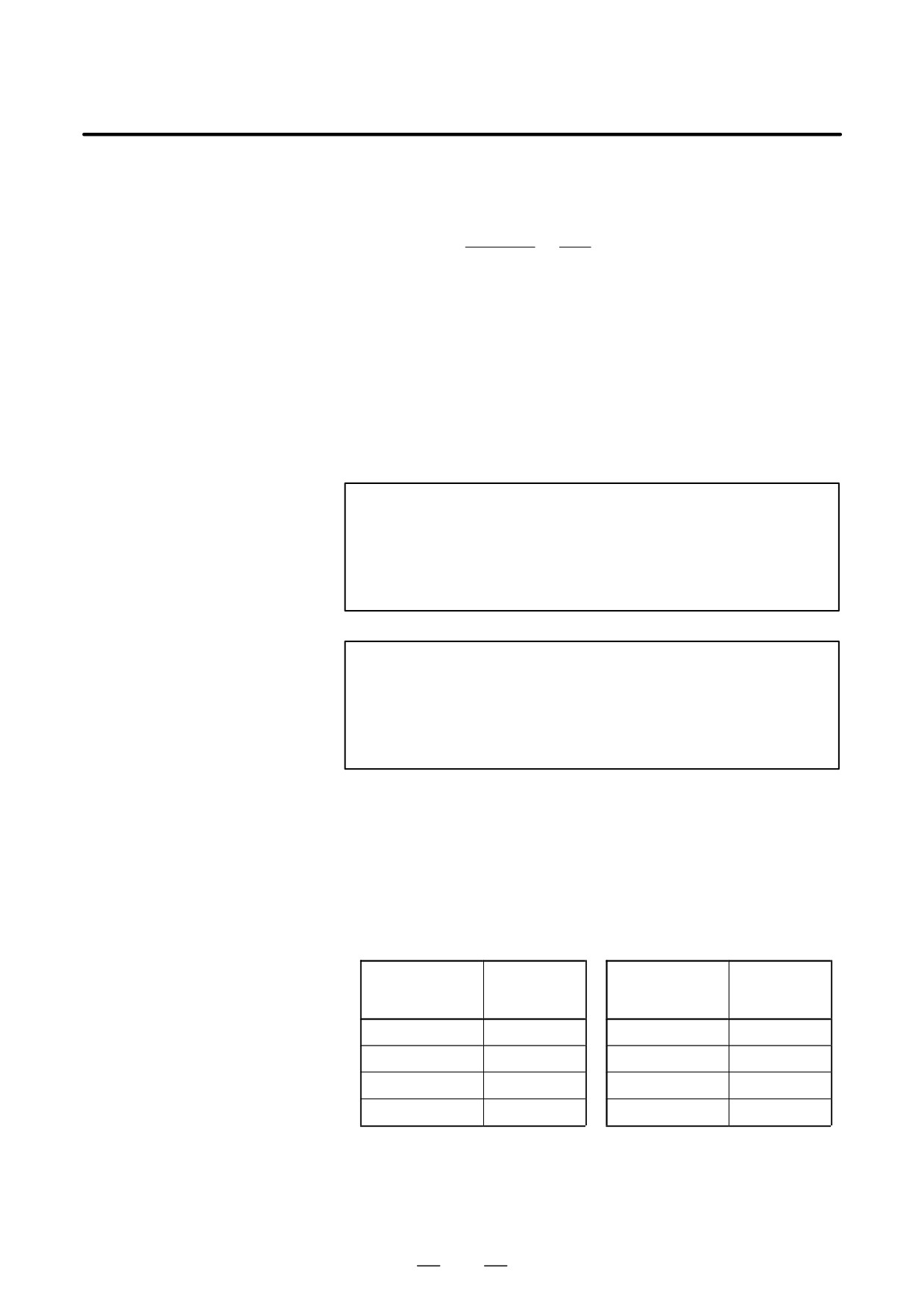
D Notes on parameter
Note the following points when specifying parameters for the electronic
settings
gear box.
1. Arrange the controlled axes such that a slave axis appears before a
dummy axis.
(Example)
Example of incorrect setting
Example of correct setting
Servo axis
Servo axis
Axis name
number
Axis name
number
(No.1023)
(No.1023)
X
1
X
1
Y
2
Y
2
C (dummy axis)
3
C (slave axis)
3
C (slave axis)
4
C (dummy axis)
4
2. Do not use a name which is usually not allowed to be used as an axis
address, such as D.
3. Specify the same values for an EGB slave axis and an EGB dummy
axis in the following parameters.
587
20. AXIS CONTROL FUNCTIONS
PROGRAMMING
B-63534EN/02
1004#7
Ten times minimum input increment
1001#0
Inch/metric switching (rotation axis/linear axis)
1006#1
Shape of machine coordinate system (rotation axis/linear
axis)
1006#2
Shape of machine coordinate system for pitch error
compensation (rotation axis/linear axis)
1420
Rapid traverse rate
1421
Rapid-traverse override F0 speed
1820
Command multiplication
4.
Specify the amount of travel per rotation about a rotation axis for a
slave axis in a parameter No. 1260.
5.
Make the specification for a dummy axis in the following way.
1815#1
Whether to use separate detectors. Although an EGB
dummy axis uses the interface of a separate detector, set
these parameters to 0.
6.
If the following parameters are not specified, an alarm (SV 417 servo
parameter invalid) may be generated. In such a case, make the
specification as described below.
20XX
Specify the same value for both a slave axis and a
dummy axis.
2084, 2085
Flexible feed gear.
Set parameters Nos. 2084 and 2085 to 1 for the
dummy axis.
7.
Specify as large a feed-forward coefficient as possible to reduce the
synchronization error. For details of parameter setting, see Feed-forward
setting of Geometric error suppression function in FANUC AC SERVO
MOTOR αi series Parameter Manual (B-65270EN) or FANUC AC
SERVO MOTOR α series Parameter Manual (B-65150EN).
588
B-63534EN/02
PROGRAMMING
20. AXIS CONTROL FUNCTIONS
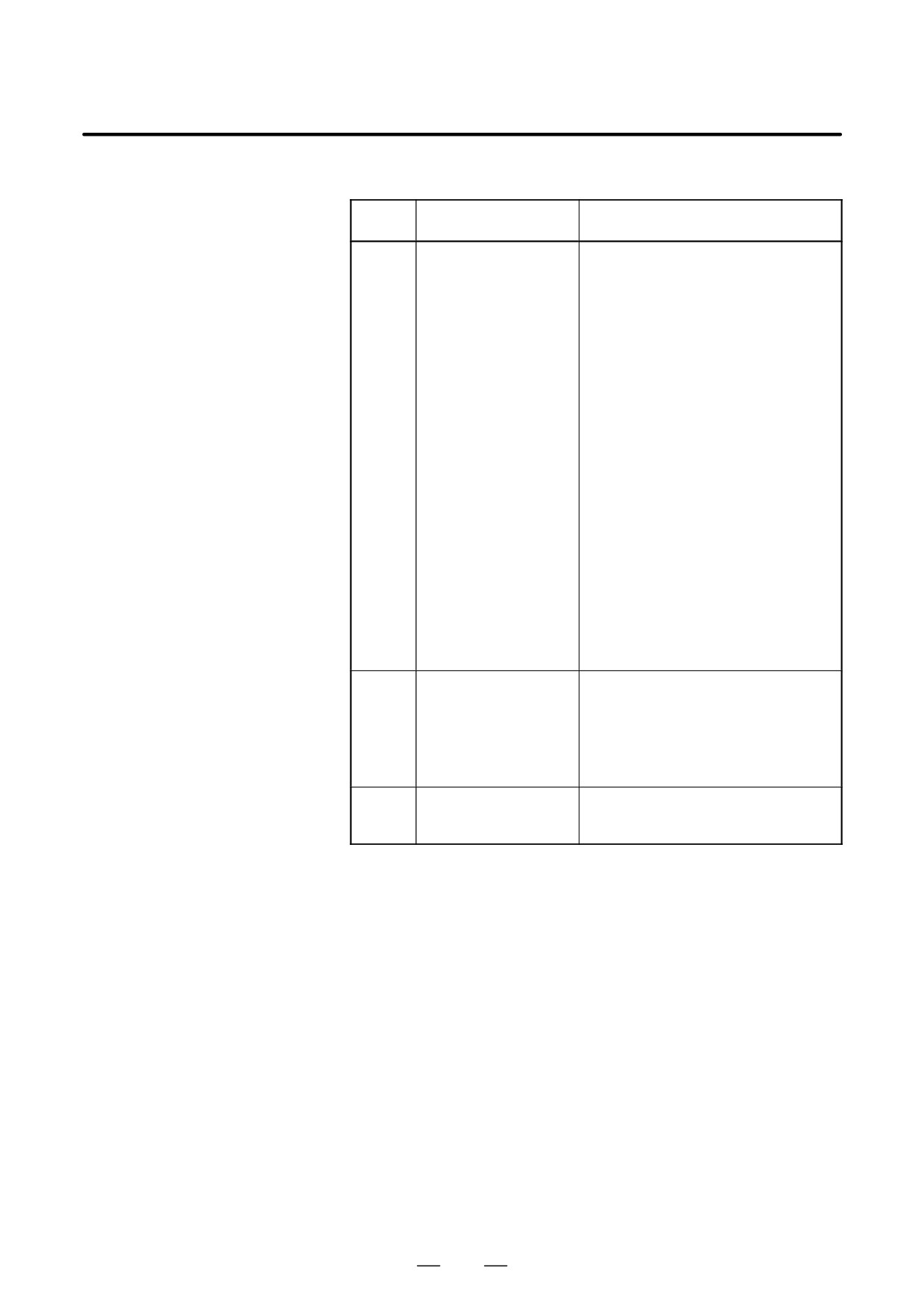
Alarms
Num-
Message
Contents
ber
P/S 181
FORMAT ERROR IN
Format error in the block in which EGB
G81 BLOCK
was specified
(1) The axis during synchronization by
EGB is specified by G81.5 again.
(2) U-axis is specified by G81.5/G80.5
with U-axis control.
(3) Format error in the block in which
G81.5/G80.5 was specified.
⋅ Data is specified to more than 2
slave axes in one block. Or noth-
ing is specified to the slave axis.
⋅ Data specified to the slave axis is
neither ‘b0 Lxx’ nor ‘bxx’.
⋅ Data is specified to more than 2
master axes in one block.
⋅ Data is specified to the axis which
is neither the master nor the slave
axis.
⋅ One of T, P or a codes is specified
redundantly.
⋅ Out of range data is specified by
one of T or L codes
⋅ An overflow occurred during cal-
culation of the synchronization co-
efficient.
P/S 184
ILLEGAL COMMAND
An illegal instruction was issued during
IN G81
synchronization by EGB.
(1) Slave axis was specified by G00,
G27, G28, G29, and G30 G codes.
(2) Inch/metric conversion was speci-
fied by G20 or G21 G codes.
P/S 186
PARAMETER SETTING
Erroneous EGB parameter setting
ERROR
The number of pulses (parameter Nos.
7782, 7783) per rotation is not set.
589
21. TWO-PATH CONTROL
FUNCTION
PROGRAMMING
B-63534EN/02
TWO-PATH CONTROL FUNCTION
21
590
21. TWO-PATH CONTROL
B-63534EN/02
PROGRAMMING
FUNCTION
The two-path control function is designed for use on a machining center
21.1
where two systems are operated independently to simultaneously perform
GENERAL
cutting.
D Controlling two path
The operations of two path are programmed independently of each other,
independently at the
and each program is stored in program memory for each path. When
same time
automatic operation is to be performed, each path is activated after
selecting a program for machining with path 1 and a program for
machining with path 2 from the programs stored in program memory for
each path. Then the programs selected for the paths are executed
independently at the same time. When path 1 and path 2 need to wait for
each other during machining, the waiting function is available (Section
21.2)
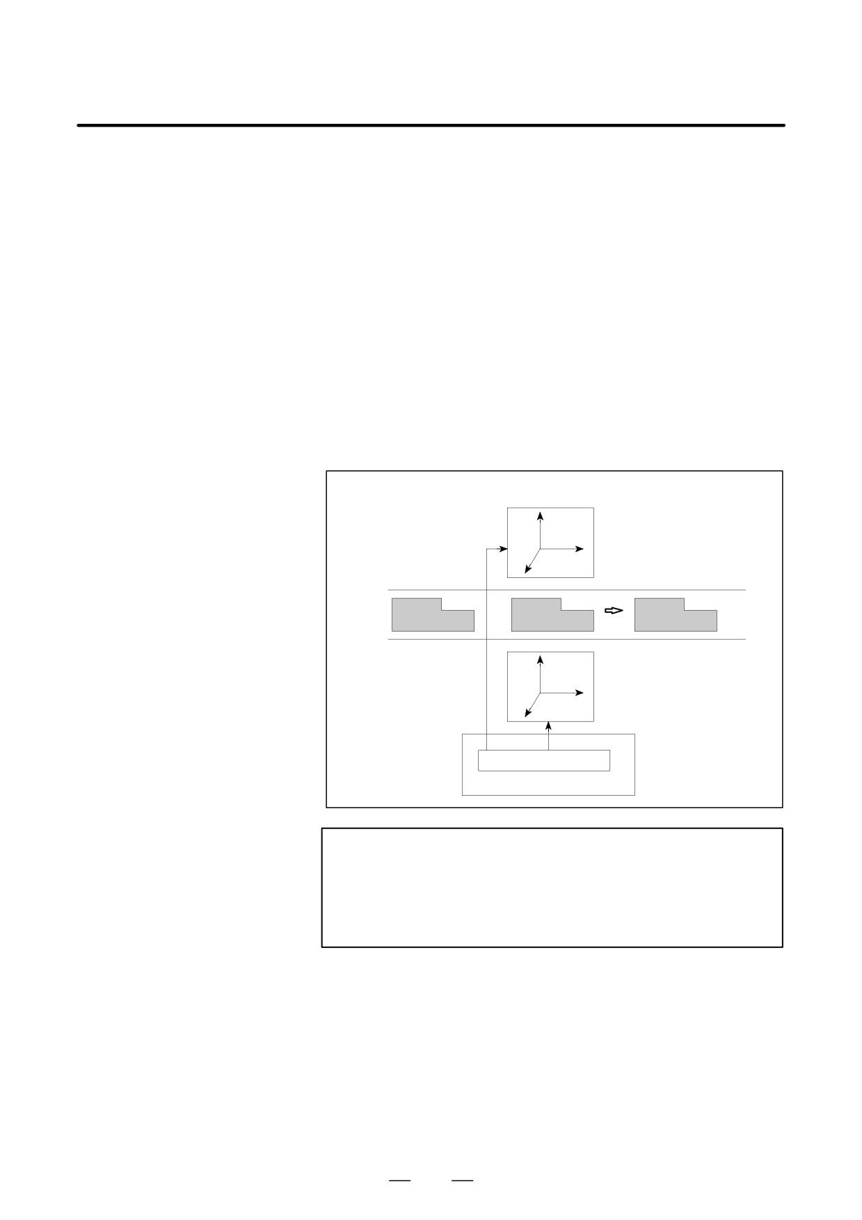
Just one MDI is provided for the two paths. Before operation and display
on the MDI, the path selection signal is used to switch between the two
paths.
Transfer Line
Machining center (Left)
Transport device
Machining center (Right)
CNC
2-path control
WARNING
Simultaneous operation of the two paths or the operation of
only a single tool post can be selected by pressing a key on
the machine operator’s panel. For details, refer to the
manual supplied by the machine tool builder.
591
21. TWO-PATH CONTROL
FUNCTION
PROGRAMMING
B-63534EN/02
21.2
WAITING FOR PATHS
Explanations
Control based on M codes is used to cause one path to wait for the other
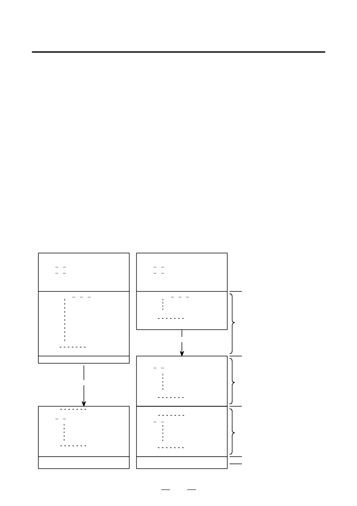
during machining. By specifying an M code in a machining program for
each path, the two paths can wait for each other at a specified block. When
an M code for waiting is specified in a block for one path during automatic
operation, the other path waits for the same M code to be specified before
staring the execution of the next block. This function is called the paths
waiting function.
A range of M codes used as M codes for waiting is to be set in the
parameters (Nos. 8110 and 8111) before hand.
Example
M100 to M103 are used as M codes for waiting.
Parameter setting:No. 8110=100
(Minimum M code for waiting: M100)
No. 8111=103
(Maximum M code for waiting: M103)
Path 1 program
Path 2 program
01357 ;
02468 ;
G50 X Z ;
G50 X Z ;
G00 X Z T0101 ;
G00 X Z T0202 ;
S1000 M03 ;
S2000 M03 ;
M100 ;
M100 ;
Waiting
N1100 G01 X Z F
;
N2100 G01 X Z F
;
Simultaneous,
N2199
;
independent operation
M101 ;
of path 1 (N1100 to
N1199) and path 2
(N2100 to N2199)
N1199
;
<Waiting (M101)>
M101 ;
M102 ;
Waiting
N2200 S3000 ;
G00 X Z T0202 ;
Operation of path 2
<Waiting (M102)>
(N2200 to N2299)
only
N2299
;
M102 ;
Waiting
N1300
;
Simultaneous,
N2300
;
G00 X Z T0505 ;
G00 X Z T0707 ;
independent operation
of path 1 (N1300 to
N1399) and path 2
(N2300 to N2399)
N1399
;
N2399
;
M103 ;
M103 ;
Waiting
M30 ;
M30 ;
End of program
592

21. TWO-PATH CONTROL
B-63534EN/02
PROGRAMMING
FUNCTION
NOTE
1
An M code for waiting must always be specified in a single block.
2
If one path is waiting because of an M code for waiting specified, and a different M code for
waiting is specified with the other path, an P/S alarm (No. 160) is raised, In this case, both paths
stop operation.
3
PMC-CNC interface
Unlike other M codes, the M code for waiting is not output to the PMC.
4 Operation of a single path
If the operation of a single path is required, the M code for waiting need not be deleted. By using
the NOWT signal to specify that waiting be ignored (G0063, #1), the M code for waiting in a
machining program can be ignored. For details, refer to the manual supplied by the machine
tool builder.
593
21. TWO-PATH CONTROL
FUNCTION
PROGRAMMING
B-63534EN/02
A machine with two paths have different custom macro common
21.3
variables and tool compensation memory areas for path 1 and 2. Paths 1
MEMORY COMMON
and
2 can share the custom macro common variables and tool
TO PATH
compensation memory areas provided certain parameters are specified
accordingly.
Explanations
D Custom macro common
Paths 1 and 2 can share all or part of custom macro common variables
variables
#100 to #149 and #500 to #531, provided parameters 6036 and 6037 are
specified accordingly.
(The data for the shared variables can be written
or read from either path.) See Section 15.1 of Part II.
594
21. TWO-PATH CONTROL
B-63534EN/02
PROGRAMMING
FUNCTION
21.4
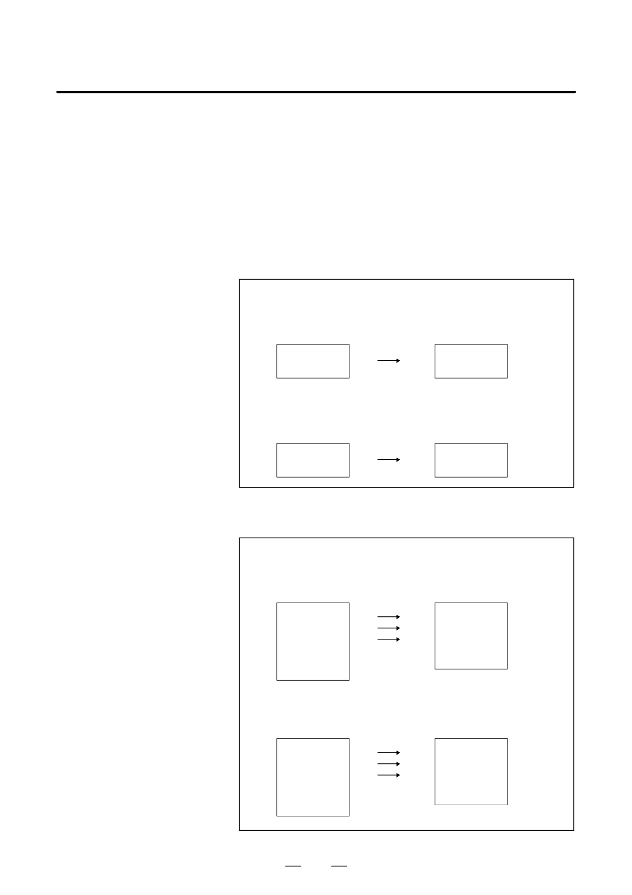
In a CNC supporting two-path control, specified machining programs
can be copied between the two paths by setting bit 0 (PCP) of parameter
COPYING A
No. 3206 to 1. A copy operation can be performed by specifying either
PROGRAM
a single program or a range. For information about operations, see
BETWEEN TWO
Section 9.10 in Part III.
PATHS
Explanations
D Single-program copy
Copy source number
:
0001
Copy destination number
: Not set
Copy source
Copy destination
O0001
O0001
Copy source number
:
0001
Copy destination
:
0010
Copy source
Copy destination
O0001
O0010
D Specified-range copy
Copy source number
:
0001 to 0100
Copy destination number
: Not set
Copy source
Copy destination
O0001
O0001
O0010
O0010
O0100
O0100
O1000
O2000
Copy source number
:
0001 to 0100
Copy destination
:
1000
Copy source
Copy destination
O0001
O1000
O0010
O1001
O0100
O1002
O1000
O2000
595

22. RISC PROCESSOR
PROGRAMMING
B-63534EN/02
RISC PROCESSOR
22
General
The following functions are executed at high speed with RISC processor.
D AI high precision contour control
D AI NANO high precision contour control
D Cylindrical interpolation cutting point control
D Tool center point control
D Tool axis compensation in tool axis direction
D 3-dimensional cutter compensation
D 3-dimensional circular interpolation
Expansion of RISC
The parameter(No.19600#0-#5) setting expands the following functions
commnd
which is executed with RISC processor.
5-axis control mode
function
mode ON
mode OFF
G51
G50
Scaling
G51.1
G50.1
Programmable mirror image
G54.2 Pn
G54.2 P0
Rotary table dynamic fixture offset
(n=1-8)
G68
G69
Coordinate system rotation
G68 I_J_K_
G69
3-dimensional coordinate system
conversion
G41,G42
G40
Cutter compensation C
AI high precision contour control, AI NANO high precision contour
control, Tool center point control, Tool axis compensation in tool axis
direction,
3-dimensional cutter compensation and
3-dimensional
circular interpolation can be used in the mode of above mentioned
functions when the above mentioned function is set to be executed with
RISC processor.
Please refer to paragraph of restrictions for the restriction in this case.
AI high precision contour control, AI NANO high precision contour
control, Tool center point control, Tool axis compensation in tool axis
direction,
3-dimensional cutter compensation and
3-dimensional
circular interpolation can be used only when the state of the above
mentioned functions is canceling when the above mentioned function is
set to be executed with CNC.
The alarm(P/S5012) occurs if AI high precision contour control, AI
NANO high precision contour control, Tool center point control, Tool
axis compensation in tool axis direction,
3-dimensional cutter
compensation and 3-dimensional circular interpolation is used when the
state of the above mentioned function is not canceling.
596
B-63534EN/02
PROGRAMMING
22. RISC PROCESSOR
5-axis control mode
The state to execute the each function of AI high precision contour
control, AI NANO high precision contour control, Tool center point
control, Tool axis compensation in tool axis direction, 3-dimensional
cutter compensation and
3-dimensional circular interpolation is
generically called five axis control mode.
The function set in the expansion of RISC command is included, too.
Restriction -1
The following commands can not be used in the AI High Precision
Contour Control mode or AI NANO High Precision Contour Control
mode. The alarm is issued if the function was used.
S
Custom macro
S
Exponential interpolation
-G02.3,G03.3
S
Dwell
-G04
S
High Speed Cutting Function relation
-G05
(G05P10000 and G05P0 are excluded)
S
AI contour control
-G05.1Q1,G5.1Q0
S
Hypothetical axis interpolation
-G07
S
Advanced preview control
-G08
(Please use AI High Precision Contour Control)
S
Polar coordinate interpolation
-G12.1,G13.1
S
Polar coordinate command
-G15,G16
S
Reference position return check
-G27
S
Reference point return
-G28
S
2nd. Reference point return
-G30
S
3rd/4th reference point return
-G30
S
Skip
-G31
S
Thread cutting
-G33
S
Automatic tool length measurement
-G37
S
Normal direction control
-G40.1,G41.1,G42.1
S
Cutter compensation B
-G41,G42,G39
(Cutter compensation C is available)
S
3-dimensional tool compensation
-G41
S
Wheel wear compensation
-G41
S
Tool offset
-G45,G46,G47,G48
S
Local coordinate system
-G52
S
Machine coordinate system
-G53
S
Single direction positioning
-G60
S
Automatic corner override
-G62
S
Tapping mode
-G63
S
Macro call
-G65,G66,G67
(SubProgram call is available)
S
Figure copying
-G72.1,G72.2
S
Simple electric gear box
-G80,G81
S
Functions for hobbing machine
-G80,G81
597
22. RISC PROCESSOR
PROGRAMMING
B-63534EN/02
S External operation function
-G81
S Chopping function
-G81.1
S Setting a workpiece coordinate system
-G92
S Workpiece coordinate system preset
-G92.1
S Feed per revolution
-G95
S Constant surface speed control
-G96,G97
S Infeed control
-G160,G161
Restriction -2
The following functions can not be used in the AI High Precision Contour
Control mode, the AI NANO High Precision Contour Control mode or
the 5-axis control mode.
S Flexible synchronous control
S Sequence number comparison and stop
It is not possible to stop by the sequence number in the AI High
Precision Contour Control mode , in the AI Nano High Precision
Contour Control mode or in the 5-axis control mode.
S Index table indexing
S Retrace function
Do not use retrace function in the program which uses the AI
High Precision Contour Control mode or the AI Nano High
Precision Contour Control or 5-axis control mode.
S Rotary axis control
S Gentle curve normal direction control
S Tool life management
Tool life value is counted in the AI High Precision Contour
Control mode or in the AI Nano AI High Precision Contour
Control mode. However , do not use the command related to the
tool life management function.
S Macro executor (Execution macro)
S Manual handle interruption
S Feedrate change of F1 digit feed by manual pulse generator
S External deceleration (External deceleration is not aviailable )
Restriction -3
The following commands can not be used in the 5-axis control mode. The
alarm is issued if the function was used.
- M,S,T and B function with motion command
- NURBS interpolation
-G06.2
– Workpiece coordinate system
-G54-G59, G54.1
– Canned cycle
-G73 to G79,
G80 to G89,G98,G99
- Manual interruption operaton
- Tool retract and recover
Restriction -4
In the 5-axis control mode, the following functions cannot be used, The
warning message is displayed on the screen when the following functions
are used. :
598
B-63534EN/02
PROGRAMMING
22. RISC PROCESSOR
– MDI intervention
Restriction -5
When the following function is used, the function which executed with
RISC processor cannot be used.
S Angular axis control
S Arbitary angular axis control
Restriction -6
The following modal G code are placed in the cleared state when the reset
is executed in AI high precision contour control mode , AI NANO high
precision contour control mode or 5-axis control mode,
[Modal status]
[Clear status]
–
3-dimensional circular
-G02.4/G03.4
-G00 or G01
interpolation
-
NURBS interpolation
-G06.2
-G00 or G01
–
Cutter compensation C
-G41/G42
-G40
–
3-dimensional cutter
-G41.2,G42.2,G41.3 -G40
compensation
-
Tool axis compensation
in tool axis direction
-G43.1
-G49
–
Tool center point control
-G43.4
-G49
–
Scaling
-G51
-G50
–
Programmable mirror
-G51.1
-G50.1
image
-
Rotary table dynamic
-G54.2Pn
-G54.2P0
fixture offset
-
Coordinate system
-G68
-G69
rotation
-
3-dimensional coordinate -G68
-G69
conversion
(The alarm(P/S5453) occur when the program is restart after reset is
executed if the parameter D3R(No.5400#2) =1 in 3-dimensional
coordinate system conversion mode.
This alarm can be canceled by both <RESET> key and <CAN> key
operations pushed at the same time.)
Restriction -7
The alarm (P/S5000) occurs if, in any of the following modes, an attempt
is made to issue a command that will cause the system to enter 5-axis
control mode (tool center point control, tool axis compensation in tool
axis direction,
3-dimensional cutter compensation,
3-dimensional
circular interpolation, or a function expanded with bits 0 to 5 of parameter
No. 19600 to be executed on a RISC processor).
S Advanced preview control
S AI contour control
S AI namo contour control
Restriction -8
The limitation may be attached about the combination of the NC
instructions occasionaly. Refer the description of the each functions.
599

22. RISC PROCESSOR
PROGRAMMING
B-63534EN/02
The Function list which
can be used
Item
Specifications
Note
Axis control
Controlled axes
3 axes
Controlled paths
1-path
Simultaneously controlled axes
2 axes
Controlled axis expansion
Up to 8 axes
Simultaneously controlled axis expan-
Up to 6 axes
sion
Axis control by PMC
The axis which is used in the AI High
Precision Contour Control mode or in
the AI nano High Precision Contour
Control mode can not be used as the
control axis of the PMC Axis Control in
the AI High Precision Contour Control
mode or in the AI nano High Precision
Contour Control mode
Cs contour control
The nano interpolation and the Ad-
vanced preview feed-forward function
are canceled once when the command
for Cs axis in AI high precision contour
control mode or AI nano high precision
contour control mode
Axis name
3 basic axes: X,Y,Z; Additional axes:
U,V,W,A,B, or C
Twin table control
Synchronized operation/individual op-
eration/a normal drive cannot be
changed in the AI high precision con-
tour control mode or in the AI nano
high precision contour control mode
Please include all the twin table control
axes to the maximum control axis
number (parameter No.7510) of RISC.
Simple synchronous control
Synchronized operation/individual op-
eration/a normal drive cannot be
changed in the AI high precision con-
tour control mode or in the AI nano
high precision contour control mode
Please include all the simple synchro-
nous control axes to the maximum
control axis number (parameter
No.7510) of RISC.
Least input increment
0.001mm,0.001deg,0.0001inch
Incremental System 1/10
0.0001mm,0.0001deg,0.00001inch
Inch/metric conversion
Inch mode / metric mode cannot be
changed in the AI high precision con-
tour control mode or in the AI nano
high precision contour control mode.
600

B-63534EN/02
PROGRAMMING
22. RISC PROCESSOR
Item
Specifications
Note
Axis control
Interlock
All axes/each axis
Machine lock
All axes/each axis
Emergency stop
Stored stroke check 1
The stroke limit cannot be set by the
stroke limit external setting signal in the
AI high precision contour control mode
or in the AI nano high precision contour
control mode. Overrun on the OT limit
does not occur in the AI high precision
contour control mode or in the AI nano
high precision contour control mode.
Stored stroke check 2
The AI high precision contour control
mode or the AI nano high precision
contour control mode is automatically
canceled once and the buffering is in-
hibited if G22 or G23 is used in the AI
high Precision Contour Control mode
or in the AI high Precision Contour
Control mode,
Mirror image
Do not change the state of the signal in
the AI High Precision Contour Control
mode or AI nano High Precision Con-
tour Control mode.
Backlash compensation for each rapid
traverse and cutting feed
Operation
Automatic operation
MDI operation
The AI high precision contour control
mode or the AI nano high precision
contour control mode is automatically
canceled once and the buffering is in-
hibited if the MDI operation is used in
the AI high Precision Contour Control
mode or in the AI high Precision Con-
tour Control mode. At this time,
G05P10000 or G05P0 can not be used
by the MDI operation.
Cycle start/Feed hold
Program stop/Program end
Reset
Program restart
Program restart function is performed
with folowing functions:
NURBS interpolation, and Cylindrical
intyerpolation
Dry run
Single block
601

22. RISC PROCESSOR
PROGRAMMING
B-63534EN/02
Item
Specifications
Note
Interpolation functions
Positioning
G00
The AI high precision contour control
function or AI nano high precision con-
tour control functions except the ad-
vanced preview feed-forward function
, multi buffer function , and the nano
interpolation become invalid.
Cutting mode
G64
Linear interpolation
G01
Circular interpolation
G02,G03
Helical interpolation
(Circular interpolation) + (Linear inter-
polation for up to 2 axes)
Helical interpolation B
(Circular interpolation) + (Linear inter-
polation for up to 4 axes)
Involute interpolation
G02.2,G03.2
3-dimensional circular interpolation
G02.4,G03.4
The position is checked at the end
point of the block which cancel 3 di-
mensional circular interpolation or at
the end point of the previous block of
the 3 dimensional circular interpolation
if 3 dimensional circular interpolation is
used except in AI high precision con-
tour control mode or AI nano high pre-
cision contour control mode.
Smooth interpolation
G05.1
This function can be used in AI high
precision contour control mode or AI
nano high precision contour control
mode.
NURBS interpolation
G06.2
This function can be used in AI high
precision contour control mode or AI
nano high precision contour control
mode.
Cylindrical interpolation
G07.1
This function can be used in AI high
precision contour control mode or AI
nano high precision contour control
mode.
Cylindrical interpolation cutting point
G07.1
This function can be used in AI high
control
precision contour control mode or AI
nano high precision contour control
mode.
Conical / spiral interpolation
G02,G03
Feed functions
Feed per minute
G94
Cutting feedrate clamp
Linear acceleration/deceleration of cut-
ting feed after interpolation
602

B-63534EN/02
PROGRAMMING
22. RISC PROCESSOR
Item
Specifications
Note
Feed functions
Bell-type acceleration/deceleration of
cutting feed after interpolation
Feedrate override
0 to 254%
(1% step)
2nd. Feedrate override
0 to 254%
(1% step)
F1 digit feed
Using the manual pulse generator can
not change Feedrate.
Inverse time feed
G93
Look-ahead liner-type acceleration/
deceleration before interpolation.
Look-ahead bell-type acceleration/
Acceleration change time constant
deceleration before interpolation
type
AI high-precision contour control
AI nano high-precision contour contreol
Program input
Tape code
Automatic recognition of EIA/ISO
Program format
Word address format
Control in/out
Optional block skip
Absolute/incremental programming
G90/G91
Input unit 10 time multiply
Plane selection
G17,G18,G19
Rotary axis roll over
Workpiece coordinate system selec-
G54 to G59
The AI high precision contour control
tion
mode or the AI nano high precision
contour control mode is automatically
canceled once and the buffering is in-
hibited if this function is used in the AI
high Precision Contour Control mode
or in the AI high Precision Contour
Control mode.
Addition of workpiece coordinate sys-
48 sets / 300 sets
The AI high precision contour control
tem pair
mode or the AI nano high precision
contour control mode is automatically
canceled once and the buffering is in-
hibited if this function is used in the AI
high Precision Contour Control mode
or in the AI high Precision Contour
Control mode.
Manual absolute ON/OFF
603

22. RISC PROCESSOR
PROGRAMMING
B-63534EN/02
Item
Specifications
Note
Program input
Programmable parameter input
G10
The AI high precision contour control
mode or the AI nano high precision
contour control mode is automatically
canceled once and the buffering is in-
hibited if this function is used in the AI
high Precision Contour Control mode
or in the AI high Precision Contour
Control mode.
External memory and sub program
M198
calling function
Subprogram call
M98
Circular interpolation by R program-
ming
Scaling
G50,G51
The mode of AI high precision contour
control or of AI nano high precision
contour control is permitted to change
ON and OFF in scaling mode by set-
ting the parameter.
The alarm (P/S5012) occurs if the
mode of AI high precision contour con-
trol or of AI nano high precision con-
tour control is changed in scaling mode
(G51) when the parameter is not set.
The scaling mirror image by a negative
magnification can not be done.
Coordinate system rotation
G68,G69
The mode of AI high precision contour
control or of AI nano high precision
contour control is permitted to change
ON and OFF in coordinate system
rotation mode by setting the parameter.
The alarm (P/S5012) occurs if the
mode of AI high precision contour con-
trol or of AI nano high precision con-
tour control is changed in coordinate
system rotation mode (G51) when the
parameter is not set.
3-dimensional coordinate system con-
G68,G69
The mode of AI high precision contour
version
control or of AI nano high precision
contour control is permitted to change
ON and OFF in 3-dimensional coordi-
nate system conversion mode by set-
ting the parameter. The alarm
(P/S5012) occurs if the mode of AI
high precision contour control or of AI
nano high precision contour control is
changed in 3-dimensional coordinate
system conversion when the parame-
ter is not set.
604

B-63534EN/02
PROGRAMMING
22. RISC PROCESSOR
Item
Specifications
Note
Miscellaneous/spindle functions
Miscellaneous function
The AI high precision contour control
mode or the AI nano high precision
contour control mode is automatically
canceled once and the buffering is in-
hibited if this function is used in the AI
high Precision Contour Control mode
or in the AI high Precision Contour
Control mode.
2nd. Auxiliary function
The AI high precision contour control
mode or the AI nano high precision
contour control mode is automatically
canceled once and the buffering is in-
hibited if this function is used in the AI
high Precision Contour Control mode
or in the AI high Precision Contour
Control mode.
1 block plural M commands
The AI high precision contour control
mode or the AI nano high precision
contour control mode is automatically
canceled once and the buffering is in-
hibited if this function is used in the AI
high Precision Contour Control mode
or in the AI high Precision Contour
Control mode.
It is possible to command up to 3.
Spindle speed function
The AI high precision contour control
mode or the AI nano high precision
contour control mode is automatically
canceled once and the buffering is in-
hibited if this function is used in the AI
high Precision Contour Control mode
or in the AI high Precision Contour
Control mode.
Tool functions
Tool function (T8-digit)
The AI high precision contour control
mode or the AI nano high precision
contour control mode is automatically
canceled once and the buffering is in-
hibited if this function is used in the AI
high Precision Contour Control mode
or in the AI high Precision Contour
Control mode.
Tool length compensation
G43
Cutter compensation
G38,G39,G40,G41,G42
The buffering is inhibited when the
command which automatically cancel
AI high precision contour control mode
or AI nano high precision contour con-
trol mode is used.
So the tool offset vector is held.
605

22. RISC PROCESSOR
PROGRAMMING
B-63534EN/02
Item
Specifications
Note
Tool functions
3-dimensional tool compensation
G41.2,G42.2
The command which automatically
G41.3
cancel AI high precision contour con-
trol mode or AI nano high precision
contour control mode can not be used.
However M,S,T and B command can
be used without the command that
move some axes. In this case, the off-
set vector is held because the buffer-
ing is inhibited.
Tool axis direction tool length com-
G43.1
The command which automatically
pensation
cancel AI high precision contour con-
trol mode or AI nano high precision
contour control mode can not be used.
However M,S,T and B command can
be used without the command that
move some axes. In this case, the off-
set vector is held because the buffer-
ing is inhibited.
Tool center point control
G43.4,G43.5
The command which automatically
cancel AI high precision contour con-
trol mode or AI nano high precision
contour control mode can not be used.
However M,S,T and B command can
be used without the command that
move some axes. In this case, the off-
set vector is held because the buffer-
ing is inhibited.
Rotary table dynamic fixture offset
G54.2
The mode of AI high precision contour
control or of AI nano high precision
contour control is permitted to change
ON and OFF in rotary table dynamic
fixture offset mode by setting the pa-
rameter. The alarm (P/S5012) occurs if
the mode of AI high precision contour
control or of AI nano high precision
contour control is changed in rotary
table dynamic fixture offset mode when
the parameter is not set.
606
B-63534EN/02
PROGRAMMING
22. RISC PROCESSOR
22.1
AI HIGH PRECISION
CONTOUR CONTROL/
AI NANO HIGH
PRECISION CONTOUR
CONTROL
General
This function is designed to achieve high-speed, high-precision
machining with a program involving a sequence of very small straight
lines and NURBS curved lines, like those used for metal die machining.
This function can suppress the servo system delay and delay caused by
acceleration/deceleration that increase as a higher feedrate is used.
This function can be used to ensure that the tool strictly traces the
specified values, thus minimizing machining profile errors and achieving
high-speed, high-precision machining.
HPCC stands for high precision contour control. In AI High Precision
Countour Control mode, acceleration/deceleration is performed more
precisely than in the conventional HPCC mode, resulting in an increase
in the cutting speed.
AI Nano High Precision Countour Control can use the Nano interpolation
with all functions of AI High Precision Countour Control.
The output from the NC to the servo is usually in units of detection units.
This function allows output to the servo in units of thousandths of
detection units, thereby improving machining precision. This is
particularly effective for improving the surface roughness.
Note that the positioning precision depends on the machine conditions,
such as the resolution of the detector.
AI Nano High Precision Countour Control is the same as a AI High
Precision Countour Control excluding being able to use the Nano
interpolation.
In the following explanations, only AI High Precision Countour Control
is described.
Format
The following command turns AI high precision contour control mode on
and off.
In AI high precision contour control mode, ”AI HPCC” flashes at the
lower right corner of the screen.
In AI nano high precision contour control mode, ”NANO HP” flashes.
G05 P10000
: AI High Precision Countour Control mode on
G05 P0
: AI High Precision Countour Control mode off
Specify G05 alone in a block.
Functions enabled
In AI High Precision Countour Control mode, the following functions are
enabled:
Thus, this function can be used to ensure that the tool strictly traces the
specified values, thus minimizing machining profile errors for
higher-speed, higher-precision machining.
607
22. RISC PROCESSOR
PROGRAMMING
B-63534EN/02
(1) Linear acceleration/deceleration before interpolation or bell-shaped
acceleration/deceleration before interpolation
(Acceleration change time constant type)
(2) Deceleration function based on feedrate differences at corners
(3) Advanced feed-forward function
(4) Feedrate determination based on acceleration on each axis
(5) Deceleration function based on Z-axis fall angle
(6)
200-block multi-buffer function
22.1.1
Look-ahead
Acceleration/Decelerati
on Before Interpolation
Acceleration/
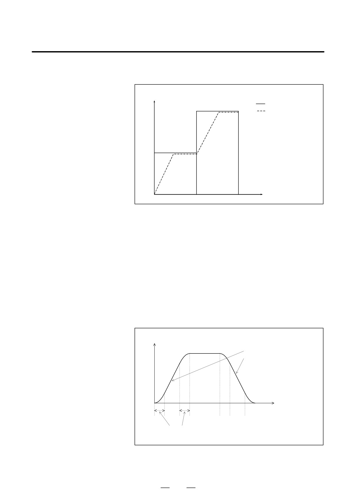
There are two types of acceleration/deceleration, the linear
deceleration types
acceleration/deceleration type and the bell-shaped acceleration/
deceleration type. When bit 7(BDO) and bit 1(NBL) of parameter
No.8402 is set to 1 or bit 3(RSB) of parameter No.1603 is set to 1,
bell-shaped acceleration/deceleration is assumed.
Bell-shaped
acceleration / deceleration produces smoother acceleration / deceleration.
Look-ahead linear
acceleration/deceleration
before interpolation
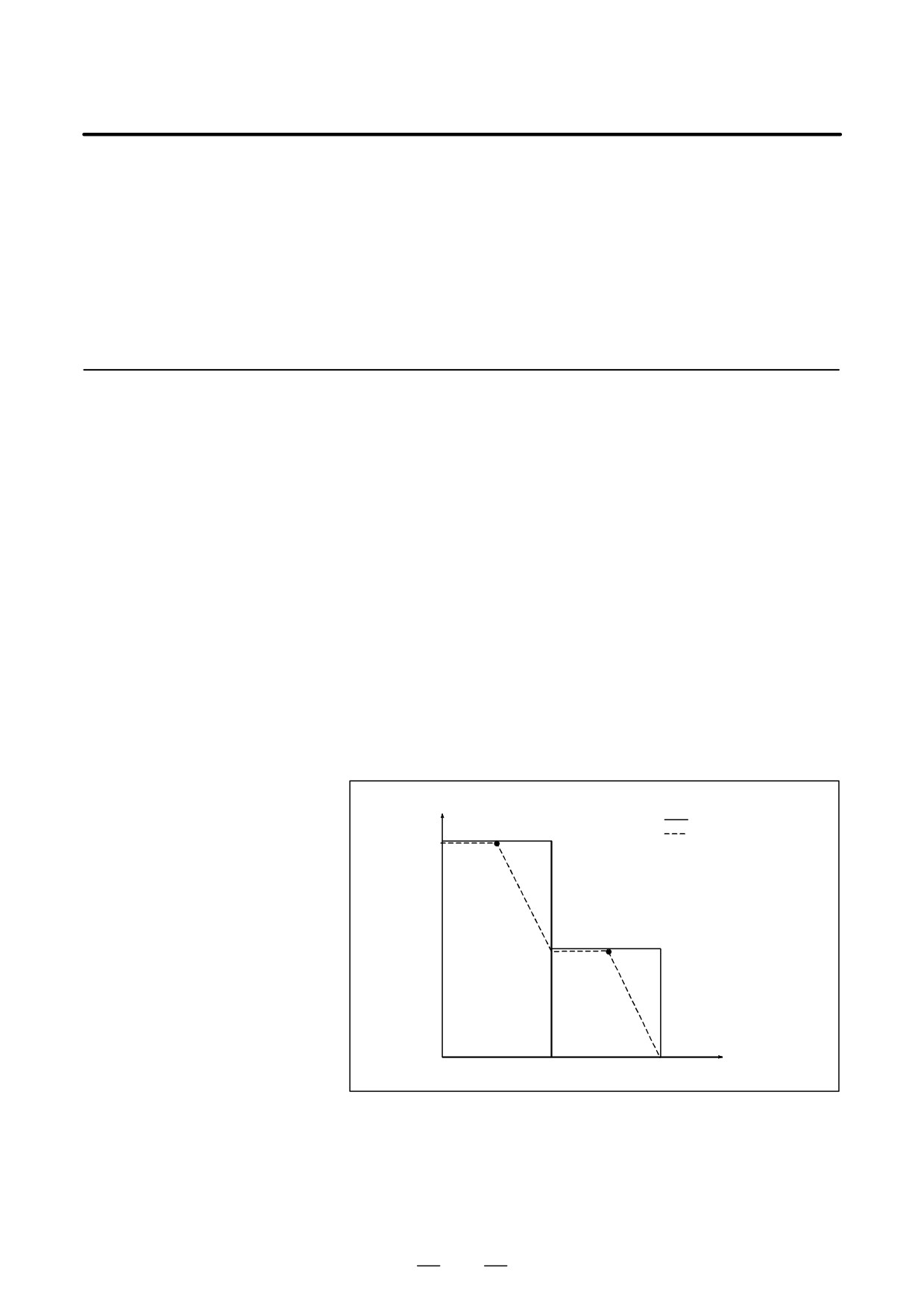
D Example of deceleration
Deceleration starts in advance so that the feedrate specified for a block can
be attained when the block is executed.
Feedrate
Programmed speed
Feedrate obtained by
F3
acceleration/
P1
deceleration
beforeinterpolation
F2
P2
F1
Time
N1
N2
To decrease the feedrate from F3 to F2, deceleration must be started from
P1.
To decrease the feedrate from F2 to F1, deceleration must be started from
P2.
Because multiple blocks are read in advance, deceleration can be
performed over all those blocks.
608
B-63534EN/02
PROGRAMMING
22. RISC PROCESSOR
D Example of acceleration
Acceleration is performed so that the feedrate specified for a block is
attained when the block is executed.
Feedrate
Programmed speed
F3
Feedrate obtained by
acceleration/
deceleration
beforeinterpolation
F2
F1
Time
N1
N2
Look-ahead bell-shaped If “1” is set to bit 7(BDO) and bit 1(NBL) of parameter No.8402 or bit
3(RSB) of parameter No.1603, bell-shaped acceleration/deceleration is
acceleration/deceleration
applied as the acceleration/deceleration before interpolation.
before interpolation
D Setting an acceleration
A permissible acceleration for the linear acceleration/deceleration of each
axis is set in parameter 19510. Acceleration change time (B) (period of
transition from constant speed state
(A) to constant acceleration/
deceleration state (C)) is set in parameter 8416 (common to all axes). In
the constant acceleration/deceleration state (C), acceleration/deceleration
is performed with the maximum tangential acceleration not exceeding the
permissible acceleration of each axis specified in parameter 19510.
The acceleration change time specified in parameter
8416 is held
constant, regardless of the tangential acceleration.
Tangential feedrate
An optimum gradient is automatically
calculated from the setting made in
parameter 19510.
(A)
(B)
(C)
(B)
(A)
(B)
(C)
(B)
(A)
Time set in parameter 8416
609