FANUC Series 16i/160i/160is-MB, Series 18i/180i/180is-MB5, Series 18i/180i/180is-MB. Operator's Manual - page 19
19. HIGH SPEED CUTTING FUNCTIONS
PROGRAMMING
B-63534EN/02
Table. 19.10 (c) Example of setting parameters related to
acceleration pattern (2/2)
Parameter
Setting
Unit
Remarks
No.
Accelera-
19546,19552
18712
0.01%
At P1, 90(Nm) can be used for
tion at P1
19558,19564
the acceleration/deceleration,
so set the ratio 7717 (mm/sec2)
to 4124 (mm/sec2).
1.8712 = 7717/4124
Accelera-
19547-19549
0
0.01%
0 is set because P2 to P4 are
tion at P2
19553-19555
skipped.
to P4
19559-19561
19565-19567
Accelera-
19550,19556
14345
0.01%
At P5, 69(Nm) can be used for
tion at P5
19562,19568
the acceleration/deceleration,
so set the ratio 5916 (mm/sec2)
to 4124 (mm/sec2).
1.4345 = 5916/4124
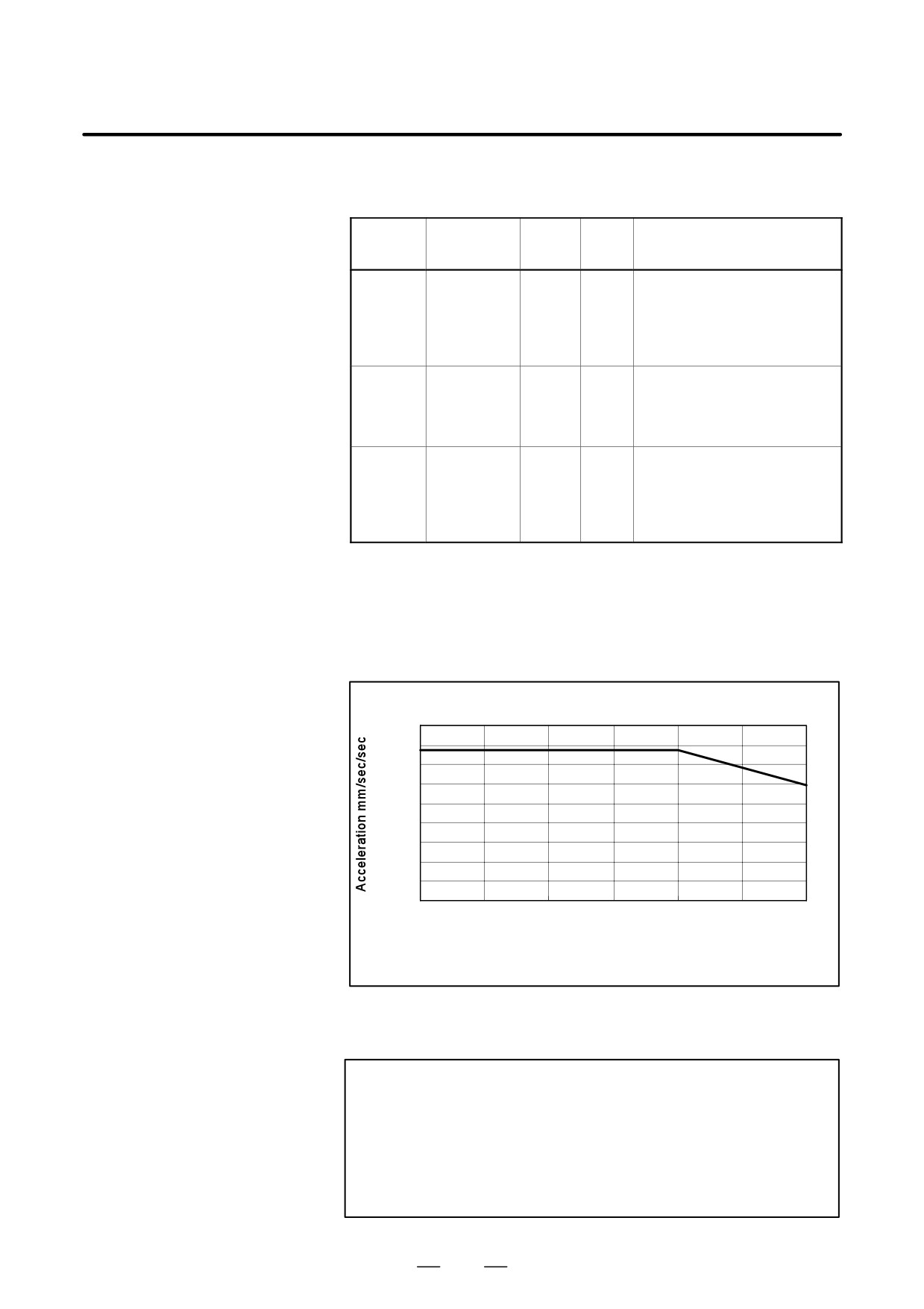
With the above parameter settings, the acceleration pattern will be shown
as the following figure. The acceleration is 7716 (mm/sec2) in case speed
is up to 32000 (mm/min) and acceleration is calculated according to the
following figure in case speed is from 32000 (mm/min) up to 48000
(mm/min).
9000
P0
P1
8000
7000
6000
P5
5000
4000
3000
2000
1000
0
0
16000
32000
48000
Speed mm/min
Fig.19.10 (f) Acceleration pattern with consideration of friction
NOTE
The values in the model a30/4000i speed-torque
characteristic diagram are just typical ones. The values will
change depending on the digital servo software,
parameters, input voltage, and other factors.
The optimum acceleration will, therefore, change due to the
characteristics of the machine.
520
B-63534EN/02
PROGRAMMING
19. HIGH SPEED CUTTING FUNCTIONS
D Examples of setting if
From the effect of gravity and friction, torque for acceleration/deceleration
the acceleration pattern
is different on each condition, such as acceleration, deceleration or plus move
differs depending on
(up), minus move (down).
whether acceleration or
The following example is for the vertical axis and gravity and friction torque
deceleration is in
are assumed as follows.
progress and whether
Torque of gravity : 20 (Nm)
the movement is in the
Torque of friction : 10 (Nm)
minus or plus direction
Because these value are different on each machine, it is necessary to observe
the output torque on the actual machine for deciding acceleration pattern
The conditions are the same as the previous example.
Motor speed at rapid traverse
:
3000 (min-1)
Ball screw pitch
:
16 (mm)
Inertia
: The machine inertia is to be 2.0
times higher than that of the rotor.
Rotor inertia
:
0.0099 (Kgm2)
Maximum torque
:
100 (Nm) Speed: 0 to 2000 (min-1)
Torque at rapid traverse
:
79 (Nm) Speed: 3000 (min-1)
Minimum torque
:
58 (Nm) Speed: 4000 (min-1)
(1) In case of plus move (up) and acceleration
Because torque of Gravity and friction work against the output torque of
motor, the torque for acceleration/deceleration is as follows.
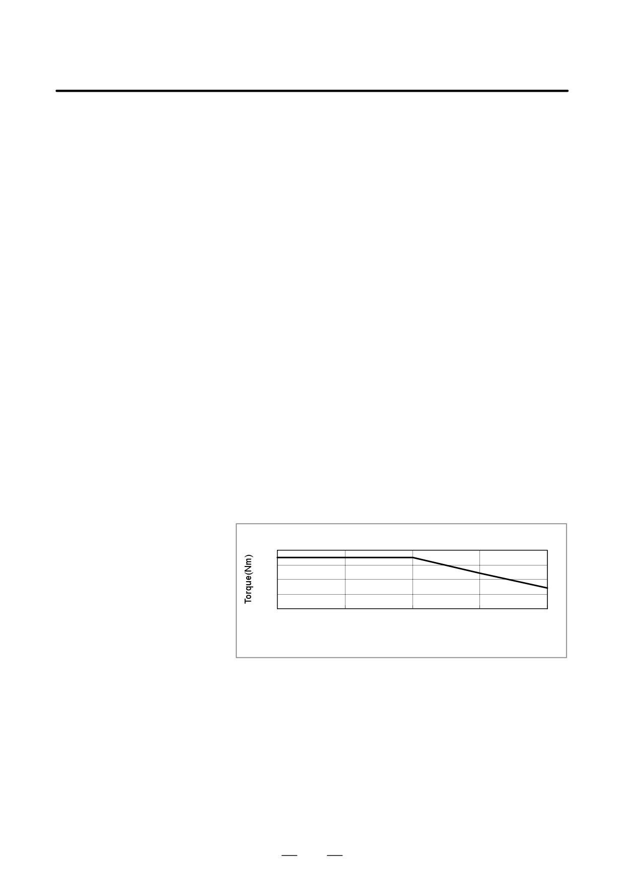
Maximum torque
:
70(=100-20-10) (Nm)
Speed: 0 to 2000 (min-1)
Torque at rapid traverse
:
49(=79-20-10) (Nm)
Speed: 3000 (min-1)
Minimum torque
:
28(=58-20-10) (Nm)
Speed: 4000 (min-1)
P0
P1
80
60
P5
40
20
0
0
1000
2000
3000
4000
Speed(min-1)
Fig.19.10(g) Torque for Acc/Dec in case of + move and acceleration
521
19. HIGH SPEED CUTTING FUNCTIONS
PROGRAMMING
B-63534EN/02
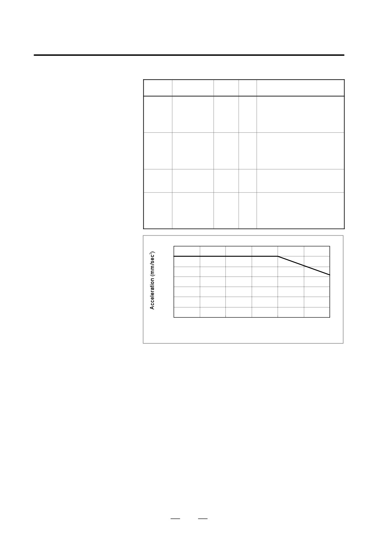
Parameter setting is as follows,
Parameter
Setting
Unit
Remarks
No.
Accel-
19545
14554
0.01
At P0, 70(Nm) can be used for
eration at
%
the acceleration/deceleration, so
P0
set the ratio 6002 (mm/sec2) to
4124 (mm/sec2). 1.4554 =
6002/4124
Accel-
19546
14554
0.01
At P1, 70(Nm) can be used for
eration at
%
the acceleration/deceleration, so
P1
set the ratio 6002 (mm/sec2) to
4124 (mm/sec2). 1.4554 =
6002/4124
Accel-
19547-19549
0
0.01
0 is set because P2 to P4 are
eration at
%
skipped.
P2 -P4
Accel-
19550
10187
0.01
At P5, 49(Nm) can be used for
eration at
%
the acceleration/deceleration, so
P5
set the ratio 4201 (mm/sec2) to
4124 (mm/sec2). 1.0187 =
4201/4124
7000
P0
P1
6000
5000
4000
P5
3000
2000
1000
0
0
16000
32000
48000
Speed (mm/min)
Fig.19.10(h) Acceleration pattern in case of + move and acceleration
(2) In case of plus move (up) and deceleration
Because torque of Gravity and friction work forward to the output torque
of motor, the torque for acceleration/deceleration is as follows.
Maximum torque
:
130(=100+20+10) (Nm)
Speed: 0 to 2000 (min-1)
Torque at rapid traverse
:
109(=79+20+10) (Nm)
Speed: 3000 (min-1)
Minimum torque
:
88(=58+20+10) (Nm)
Speed: 4000 (min-1)
522
B-63534EN/02
PROGRAMMING
19. HIGH SPEED CUTTING FUNCTIONS
P0
P1
150
P5
100
50
0
0
1000
2000
3000
4000
Speed(min-1)
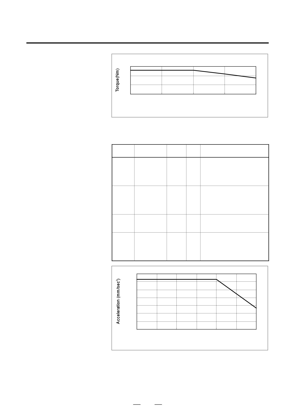
Fig.19.10(i) Torque for Acc/Dec in case of + move and deceleration
Parameter setting is as follows,
Parameter
Setting
Unit
Remarks
No.
Accel-
19557
27027
0.01
At P0, 130(Nm) can be used for
eration at
%
the acceleration/deceleration, so
P0
set the ratio 11146 (mm/sec2) to
4124 (mm/sec2). 2.7027 =
11146/4124
Accel-
19558
27027
0.01
At P1, 130(Nm) can be used for
eration at
%
the acceleration/deceleration, so
P1
set the ratio 11146 (mm/sec2) to
4124 (mm/sec2). 2.7027 =
11146/4124
Accel-
19559-19561
0
0.01
0 is set because P2 to P4 are
eration at
%
skipped.
P2 -P4
Accel-
19562
22662
0.01
At P5, 109(Nm) can be used for
eration at
%
the acceleration/deceleration, so
P5
set the ratio 9346 (mm/sec2) to
4124 (mm/sec2). 2.2662 =
9346/4124
11500
P0
P1
11000
10500
10000
9500
P5
9000
8500
8000
0
16000
32000
48000
Speed (mm/min)
Fig.19.10(j) Acceleration pattern in case of + move and deceleration
523
19. HIGH SPEED CUTTING FUNCTIONS
PROGRAMMING
B-63534EN/02
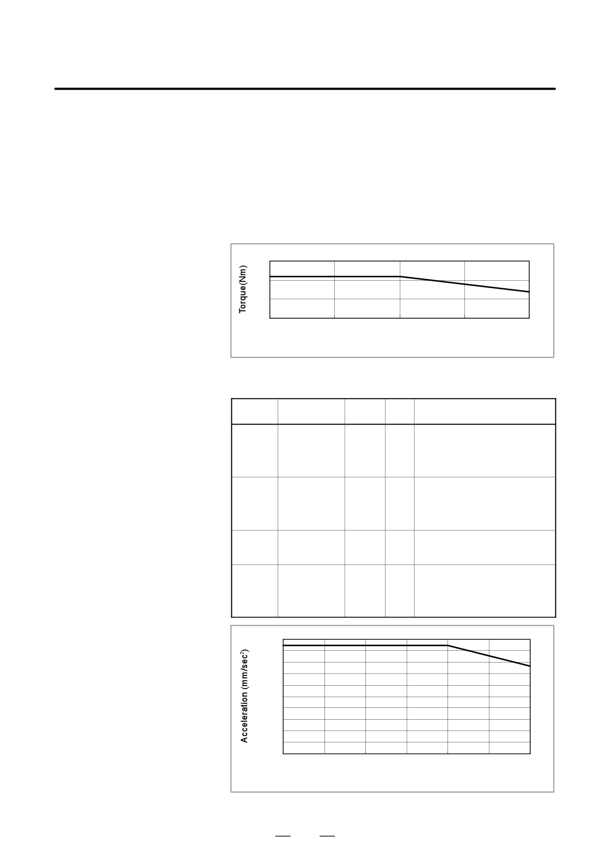
(3) In case of minus move (down) and acceleration
Because torque of Gravity works forward to the output torque of motor
and torque of friction works against the output torque of motor, torque for
acceleration/deceleration is as follows.
Maximum torque
:
110(=100+20-10) (Nm)
Speed: 0 to 2000 (min-1)
Torque at rapid traverse
:
89(=79+20-10) (Nm)
Speed: 3000 (min-1)
Minimum torque
:
68(=58+20-10) (Nm)
Speed: 4000 (min-1)
P0
P1
150
P5
100
50
0
0
1000
2000
3000
4000
Speed(min-1)
Fig.19.10(k) Torque for Acc/Dec in case of - move and acceleration
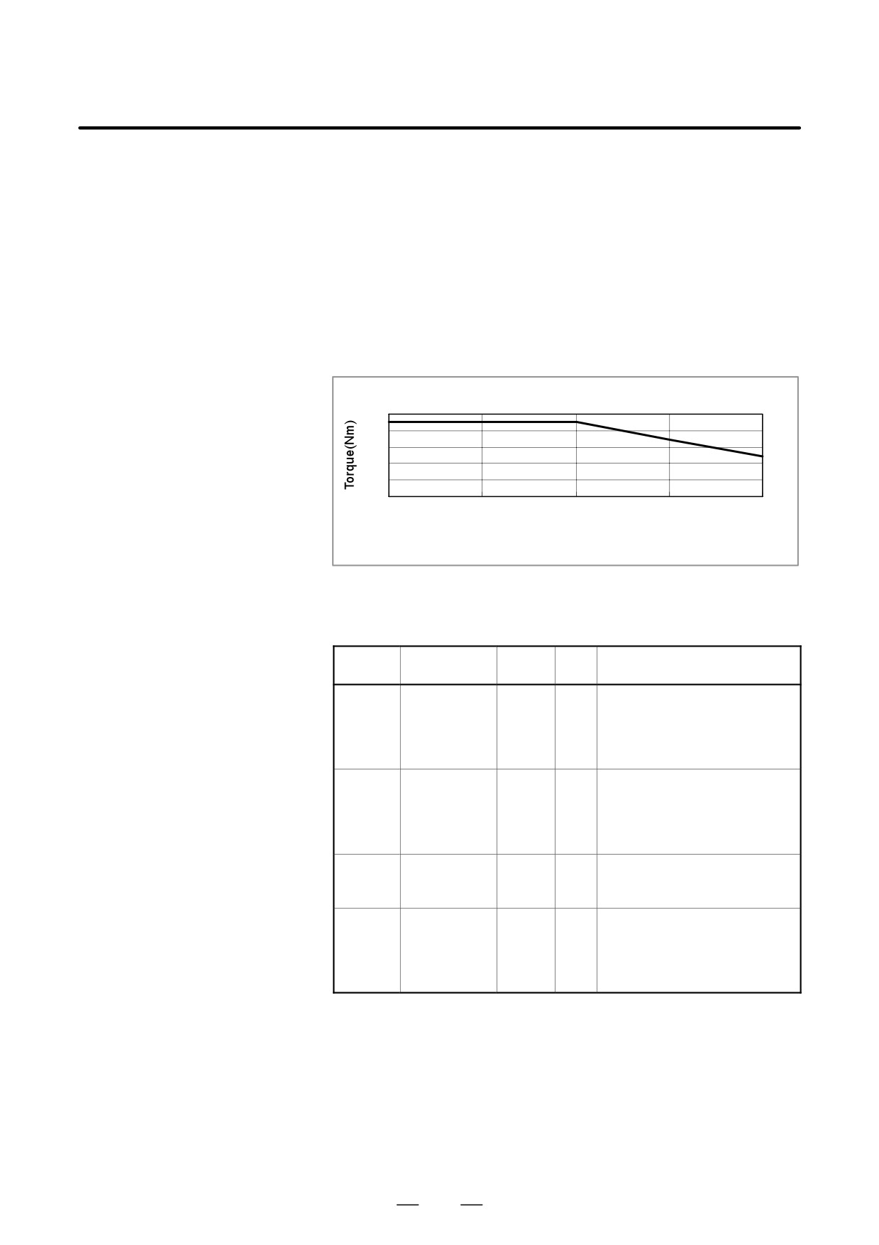
Parameter setting is as follows,
Parameter
Setting
Unit
Remarks
No.
Accel-
19551
22869
0.01
At P0, 110(Nm) can be used for
eration at
%
the acceleration/deceleration, so
P0
set the ratio 9431 (mm/sec2) to
4124 (mm/sec2). 2.2869 =
9431/4124
Accel-
19552
22869
0.01
At P1, 110(Nm) can be used for
eration at
%
the acceleration/deceleration, so
P1
set the ratio 9431 (mm/sec2) to
4124 (mm/sec2). 2.2869 =
9431/4124
Accel-
19553-19555
0
0.01
0 is set because P2 to P4 are
eration at
%
skipped.
P2 -P4
Accel-
19556
18504
0.01
At P5, 89(Nm) can be used for
eration at
%
the acceleration/deceleration, so
P5
set the ratio 7631 (mm/sec2) to
4124 (mm/sec2). 1.8504 =
7631/4124
P0
P1
10000
9000
8000
P5
7000
6000
5000
4000
3000
2000
1000
0
0
16000
32000
48000
Speed (mm/min)
Fig.19.10(l) Acceleration pattern in case of - move and acceleration
524
B-63534EN/02
PROGRAMMING
19. HIGH SPEED CUTTING FUNCTIONS
(4) In case of minus move (down) and deceleration
Because torque of Gravity works against the output torque of motor and
torque of friction works forward to the output torque of motor, torque for
acceleration/deceleration is as follows.
Maximum torque
:
90(=100-20+10) (Nm)
Speed: 0 to 2000 (min-1)
Torque at rapid traverse
:
69(=79-20+10) (Nm)
Speed: 3000 (min-1)
Minimum torque
:
48(=58-20+10) (Nm)
Speed: 4000 (min-1)
P0
P1
100
P5
80
60
40
20
0
0
1000
2000
3000
4000
Speed(min-1)
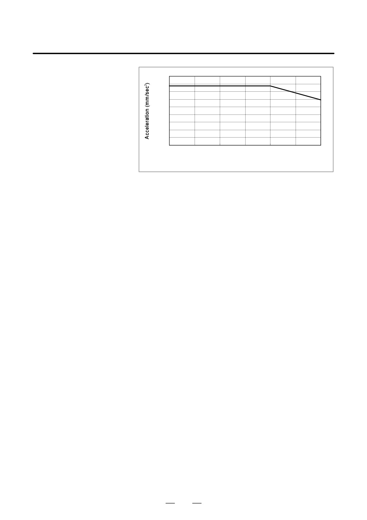
Fig.19.10(m) Torque for Acc/Dec in case of - move and deceleration
Parameter setting is as follows,
Parameter
Setting
Unit
Remarks
No.
Accel-
19563
18712
0.01
At P0, 90(Nm) can be used for
eration at
%
the acceleration/deceleration, so
P0
set the ratio 7717 (mm/sec2) to
4124 (mm/sec2). 1.8712 =
7717/4124
Accel-
19564
18712
0.01
At P1, 90(Nm) can be used for
eration at
%
the acceleration/deceleration, so
P1
set the ratio 7717 (mm/sec2) to
4124 (mm/sec2). 1.8712 =
7717/4124
Accel-
19565-19567
0
0.01
0 is set because P2 to P4 are
eration at
%
skipped.
P2 -P4
Accel-
19568
14345
0.01
At P5, 69(Nm) can be used for
eration at
%
the acceleration/deceleration, so
P5
set the ratio 5916 (mm/sec2) to
4124 (mm/sec2). 1.4345 =
5916/4124
525
19. HIGH SPEED CUTTING FUNCTIONS
PROGRAMMING
B-63534EN/02
9000
P0
P1
8000
7000
6000
P5
5000
4000
3000
2000
1000
0
0
16000
32000
48000
Speed (mm/min)
Fig.19.10(n) Acceleration pattern in case of - move and deceleration
Limitations
D Linear type positioning
When Optimum torque acceleration/deceleration is enabled, linear type
positioning for rapid traverse is selected automatically in AI high
precision contour control and AI nano high precision contour control
mode even if the parameter LRP, bit 1 of parameter No. 1401, is set to 0
(nonlinear type is selected).
D Modes and conditions
Optimum torque acceleration/deceleration is enabled when AI high
precision contour control or AI nano high precision contour control mode
is active and the conditions under which AI high precision contour control
and AI nano high precision contour control are satisfied.
D Target axes
Optimum torque acceleration/deceleration can be performed on axes
which are selected by parameter No.7510.
D Acceleration pattern
In the same direction move, it is necessary that the acceleration during
deceleration is set 1/3 of one during acceleration at least.
Also, the acceleration pattern data must be set so that the time required
for the deceleration from the rapid traverse rate to a speed of 0 does not
exceed 4000 (msec). This does not include the acceleration change time
of bell-shaped acceleration/deceleration.
If the deceleration acceleration ratio or the time required for the
deceleration to a speed of 0 exceeds the above range, P/S alarm (P/S5455)
will be issued at the time rapid traverse is executed.
A slight error will occur between the specified acceleration and the actual
acceleration.
D Tool center point control
Optimum torque acceleration/deceleration is disabled in tool center point
control mode (except startup and cancellation). If this occurs, the
acceleration/deceleration for rapid traverse follows the reference
acceleration.
526
B-63534EN/02
PROGRAMMING
20. AXIS CONTROL FUNCTIONS
AXIS CONTROL FUNCTIONS
20
527
20. AXIS CONTROL FUNCTIONS
PROGRAMMING
B-63534EN/02
It is possible to change the operating mode for two or more specified axes
20.1
to either synchronous operation or normal operation by an input signal
SIMPLE
from the machine.
SYNCHRONOUS
Synchronous control can be performed for up to four pairs of axes with
the Series
16i/160i/160is, or up to three pairs with the Series
CONTROL
18i/180i/180is, according to the parameter setting (parameter No. 8311).
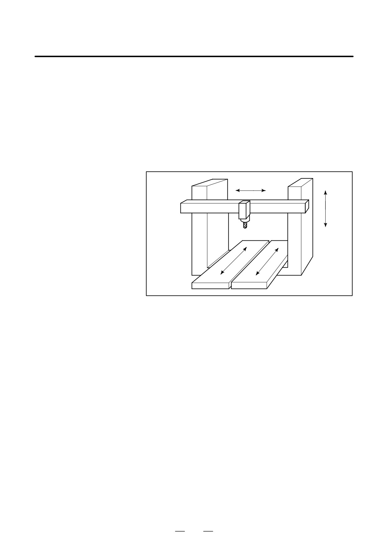
The following operating modes are applicable to machines having two
tables driven independently by separate control axes. The following
example is of a machine with two tables driven independently by the Y
axis and V axis. If the axis names and axis sets that are actually being used
differ from those in the example, substitute the actual names for those
below.
X
Z
Y
V
Fig. 20 (a) Example of axis configuration of the machine operated
by simple synchronous control
Explanations
D Synchronous operation
This mode is used for, for example, machining large workpieces that
extend over two tables.
While operating one axis with a move command, it is possible to
synchronously move the other axis. In the synchronous mode, the axis
to which the move command applies is called the master axis, and the axis
that moves synchronously with the master axis is called the slave axis.
In this example, it is assumed that Y axis is the master axis and V axis is
the slave axis. Here, the Y axis and the V axis move synchronously in
accordance with program command Yyyyy issued to the Y axis (master
axis).
Synchronous operation is possible during automatic operation, jog feed,
manual handle feed using the manual pulse generator, and incremental
feed, but is not possible during manual reference position return.
528
B-63534EN/02
PROGRAMMING
20. AXIS CONTROL FUNCTIONS
D Normal operation
This operating mode is used for machining different workpieces on each
table. The operation is the same as in ordinary CNC control, where the
movement of the master axis and slave axis is controlled by the
independent axis address (Y and V). It is possible to issue the move
commands to both the master axis and slave axis in the same block.
(1) The Y axis moves normally according to program command Yyyyy
issued to the master axis.
(2) The V axis moves normally according to program command Vvvvv
issued to the slave axis.
(3) The Y axis and the V axis move simultaneously according to program
command YyyyyVvvvv.
Both automatic and manual operations are the same as in ordinary
CNC control.
D Switching between
For how to switch between the synchronous operation and normal
synchronous operation
operation modes, refer to the relevant manual published by the machine
and normal operation
tool builder.
D Automatic reference
When the automatic reference position return command (G28) and the
position return
2nd/3rd/4th reference position return command (G30) are issued during
synchronous operation, the V axis follows the same movement as the Y
axis returns to the reference position. After the return movement is
complete, the reference position return complete signal of the V axis goes
on when that of the Y axis goes on.
As a rule, commands G28 and G30 must be issued in the normal operating
mode.
D Automatic reference
When the automatic reference position return check command (G27) is
position return check
issued during synchronous operation, the V axis and Y axis move in
tandem. If both the Y axis and the V axis have reached their respective
reference positions after the movement is complete, the reference position
return complete signals go on. If either axis is not at the reference
position, an alarm is issued. As a rule, command G27 must be issued in
the normal operating mode.
D Specifying the slave axis
When a move command is issued to the slave axis during synchronous
operation, a P/S alarm (No. 213) is issued.
D Master axis and slave
The axis to be used as the master axis is set in parameter No. 8311.
axis
The slave axis is selected by an external signal.
D Displaying actual speed
Setting bit 7 (SMF) of parameter No. 3105 to 1 suppresses display of the
for master axis only
actual speed of the slave axes.
529
20. AXIS CONTROL FUNCTIONS
PROGRAMMING
B-63534EN/02
Limitations
D Setting a coordinate
In synchronous axis control, commands that require no axis motion, such
system
as the workpiece coordinate system setup command (G92) and the local
coordinate system setup command (G52), are set to the Y axis by program
command Yyyyy issued to the master axis.
D Externally-requested
For signals such as external deceleration, interlock, and machine lock,
deceleration, interlock,
only the signals issued to the master axis are valid in the synchronous
and machine lock
operating mode. Signals issued to other axes are ignored.
D Pitch error
Both the pitch error and backlash are compensated independently for the
compensation
master axis and the slave axis.
D Manual absolute
Turn on the manual absolute switch during synchronous operation. If it
is off, the slave axis may not move correctly.
D Synchronization error
The difference between the master axis and slave axis in servo positional
check using positional
deviation is always monitored. If the difference exceeds the parameter-
deviation
set limit, an P/S alarm (No. 213) is issued.
D Synchronization error
The difference between the master axis and slave axis in machine
check using machine
coordinates is always monitored. If the difference exceeds the parameter-
coordinates
set limit, an servo alarm (No. 407) is issued.
D Synchronization
When the power is turned on, compensation pulses are output for the slave
axis to match the machine position of the master axis with the machine
position of the slave axis.
(This is enabled only when the absolute
position detection function is used.)
D Compensation for
Compensation for out-of-synchronism (where the difference between
out-of-synchronism
the master and slave axes in servo positional deviation is always
monitored and the servo motor for the slave axis is compensated to reduce
the difference) is not performed.
D Manual reference
When the machine is manually returned to the reference position during
position return
synchronous operation, both the master axis and the slave axis move
synchronously until the acceleration movement is complete. However,
grid detection thereafter is carried out independently.
530
B-63534EN/02
PROGRAMMING
20. AXIS CONTROL FUNCTIONS
20.2
ROTARY AXIS
ROLL-OVER
The roll-over function prevents coordinates for the rotation axis from
20.2.1
overflowing. The roll-over function is enabled by setting bit 0 of
Rotary Axis Roll-over
parameter ROAx 1008 to 1.
Explanations
For an incremental command, the tool moves the angle specified in the
command. For an absolute command, the coordinates after the tool has
moved are values set in parameter No. 1260, and rounded by the angle
corresponding to one rotation. The tool moves in the direction in which
the final coordinates are closest when bit 1 of parameter RABx No. 1008
is set to 0. Displayed values for relative coordinates are also rounded by
the angle corresponding to one rotation when bit 2 of parameter RRLx No.
1008 is set to 1.
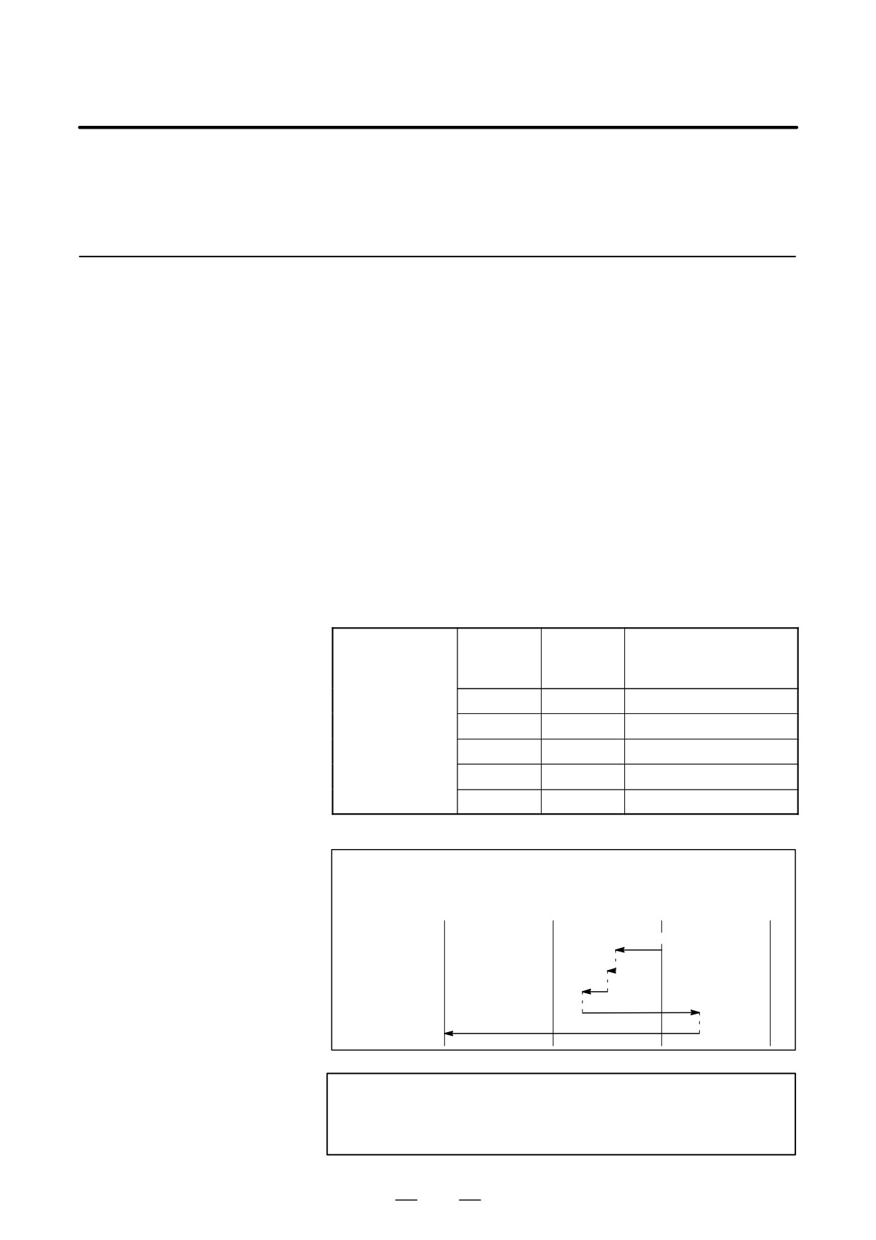
Examples
Assume that axis A is the rotating axis and that the amount of movement
per rotation is 360.000 (parameter No. 1260 = 360000). When the
following program is executed using the roll-over function of the rotating
axis, the axis moves as shown below.
Actual
Absolute coordinate
Sequence
G90 A0 ;
movement
value after movement
number
value
end
N1 G90 A-150.0 ;
N1
-150
210
N2 G90 A540.0 ;
N2
-30
180
N3 G90 A-620.0 ;
N3
-80
100
N4 G91 A380.0 ;
N4
+380
120
N5 G91 A-840.0 ;
N5
-840
0
Relative
-360°
-0°
360°
coordinate value-720°
Absolute
-0°
-0°
-0°
-0°
coordinate value
210°(Absolute)
N1
180°
N2
100°
N3
120°
N4
N5
NOTE
This function cannot be used together with the indexing
function of the index table.
531

20. AXIS CONTROL FUNCTIONS
PROGRAMMING
B-63534EN/02
20.2.2
This function controls a rotary axis as specified by an absolute command.
With this function, the sign of the value specified in the command is
Rotary Axis Control
interpreted as the direction of rotation, and the absolute value of the
specified value is interpreted as the coordinates of the target end position.
Explanations
This function is valid when rotary axis roll-over is enabled (ROAx bit (bit
0 of parameter 1008) is set to 1).
If the RAAx bit (bit 3 of parameter 1008) is set to 1, an absolute command
specified for the roll-over rotary axis is interpreted as follows: The sign
and absolute value of the value specified in the command represent the
direction of rotation and the end position of movement respectively.
If the RAAx bit (bit 3 of parameter 1008) is set to 0, the setting by the
RABx bit (bit 1 of parameter 1008) becomes significant.
Notes
NOTE
1
This function can be used only when the corresponding
option is provided.
2
This function is valid for a roll-over rotary axis.
3
If the RAAx bit (bit 3 of parameter 1008) is set to 1, the RABx
bit (bit 1 of parameter 1008) is ignored. To select a rotary
motion of a shorter travel distance, set both RAAx and RABx
to 0.
4
This function is not supported when the machine coordinate
system of the PMC axis control function is selected.
532
B-63534EN/02
PROGRAMMING
20. AXIS CONTROL FUNCTIONS
To replace the tool damaged during machining or to check the status of
20.3
machining, the tool can be withdrawn from a workpiece. The tool can
TOOL WITHDRAWAL
then be advanced again to restart machining efficiently.
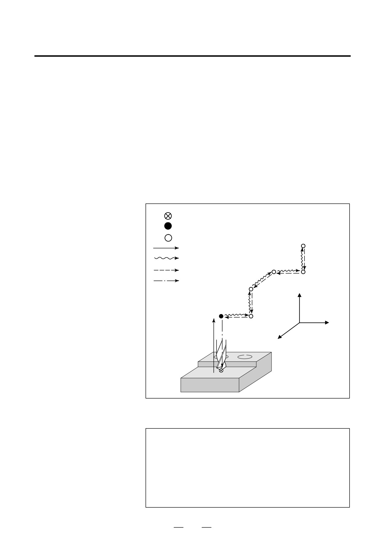
AND RETURN (G10.6)
The tool withdrawal and return operation consists of the following four
steps:
⋅ Retract
The tool is retracted to a predefined position using the TOOL WITHDRAW
switch.
⋅ Withdrawal
The tool is moved to the tool-change position manually.
⋅ Return
The tool returns to the retract position.
⋅ Repositioning
The tool returns to the interrupted position.
For the tool withdrawal and return operations, see III-4.10.
: Position where the TOOL WITHDRAW switch was turned on
: Programmed position
: Position to which the tool is retracted by manual operation
: Retraction path
: Manual operation (withdraw path)
: Return path
: Repositioning
Z
X
Y
Format
Specify a retraction axis and distance in the following format:
Specify the amount of retraction, using G10.6.
G10.6
IP
_ ;
_ : In incremental mode, retraction distance from the position
IP
where the retract signal is turned on
In the absolute mode, retraction distance to an absolute position
The specified amount of retraction is effective until G10.6 is next
executed. To cancel the retraction, specify the following:
G10.6 ; (as a single block containing no other commands)
533
20. AXIS CONTROL FUNCTIONS
PROGRAMMING
B-63534EN/02
Explanations
D Retraction
When the TOOL WITHDRAW switch on the machine operator’s panel
is turned on during automatic operation or in the automatic operation stop
or hold state, the tool is retracted the length of the programmed retraction
distance. This operation is called retraction. The position at which
retraction is completed is called the retraction position. Upon completion
of retraction, the RETRACT POSITION LED on the machine operator’s
panel goes on.
When the TOOL WITHDRAW switch is turned on during execution of
a block in automatic operation, execution of the block is interrupted
immediately and the tool is retracted. After retraction is completed, the
system enters the automatic operation hold state.
If the retraction distance and direction are not programmed, retraction is
not performed. In this state, the tool can be withdrawn and returned.
When the TOOL WITHDRAW switch is turned on in the automatic
operation stop or hold state, the tool is retracted, then the automatic
operation stop or hold state is entered again.
When the TOOL WITHDRAW switch is turned on, the tool withdraw
mode is set. When the tool withdraw mode is set, the TOOL BEING
WITHDRAWN LED on the machine operator’s panel goes on.
D Withdrawal
When the manual mode is set, the tool can be moved manually (Manual
continuous feed or manual handle feed) to replace the tool or measure a
machined workpiece. This operation is called a withdrawal. The tool
withdrawal path is automatically memorized by the CNC.
D Return
When the mode is returned to automatic operation mode and the TOOL
RETURN switch on the machine operator’s panel is turned off, the CNC
automatically moves the tool to the retraction position by tracing the
manually-moved tool path backwards. This operation is called a return.
Upon completion of a return to the retraction position, the
RETRACTIONS POSITION LED comes on.
D Repositioning
When the cycle start button is pressed while the tool is in the retraction
position, the tool moves to the position where the TOOL WITHDRAW
switch was turned on. This operation is called repositioning. Upon
completion of repositioning, the TOOL BEING WITHDRAWN LED is
turned off, indicating that the tool withdrawal mode has terminated.
Operation after completion of repositioning depends on the automatic
operation state when the tool withdrawal mode is set.
(1) When the tool withdrawal mode is set during automatic operation,
operation is resumed after completion of repositioning.
(2) When the tool withdrawal mode is set when automatic operation is
held or stopped, the original automatic operation hold or stop state is
set after completion of repositioning. When the cycle start button is
pressed again, automatic operation is resumed.
534
B-63534EN/02
PROGRAMMING
20. AXIS CONTROL FUNCTIONS
Limitations
D offset
If the origin, presetting, or workpiece origin offset value (or External
workpiece origin offset value) is changed after retraction is specified with
G10.6 in absolute mode, the change is not reflected in the retraction
position. After such changes are made, the retraction position must be
respecified with G10.6.
When the tool is damaged, automatic operation can be interrupted with
a tool withdrawal and return operation in order to replace the tool. Note
that if the tool offset value is changed after tool replacement, the change
is ignored when automatic operation is resumed from the start point or
other point in the interrupted block.
D Machine lock, mirror
When withdrawing the tool manually in the tool withdrawal mode, never
image, and scaling
use the machine lock, mirror-image, or scaling function.
D Thread cutting
Tool withdrawal and return operation cannot be performed during thread
cutting.
D Drilling canned cycle
Tool withdrawal and return operation cannot be performed during a
drilling canned cycle.
D Reset
Upon reset, the retraction data specified in G10.6 is cleared. Retraction
data needs to be specified again.
D Retraction command
The tool withdrawal and return function is enabled even when the
retraction command is not specified. In this case, retraction and
repositioning are not performed.
WARNING
The retraction axis and retraction distance specified in
G10.6 need to be changed in an appropriate block
according to the figure being machined. Be very careful
when specifying the retraction distance; an incorrect
retraction distance may damage the workpiece, machine, or
tool.
535
20. AXIS CONTROL FUNCTIONS
PROGRAMMING
B-63534EN/02
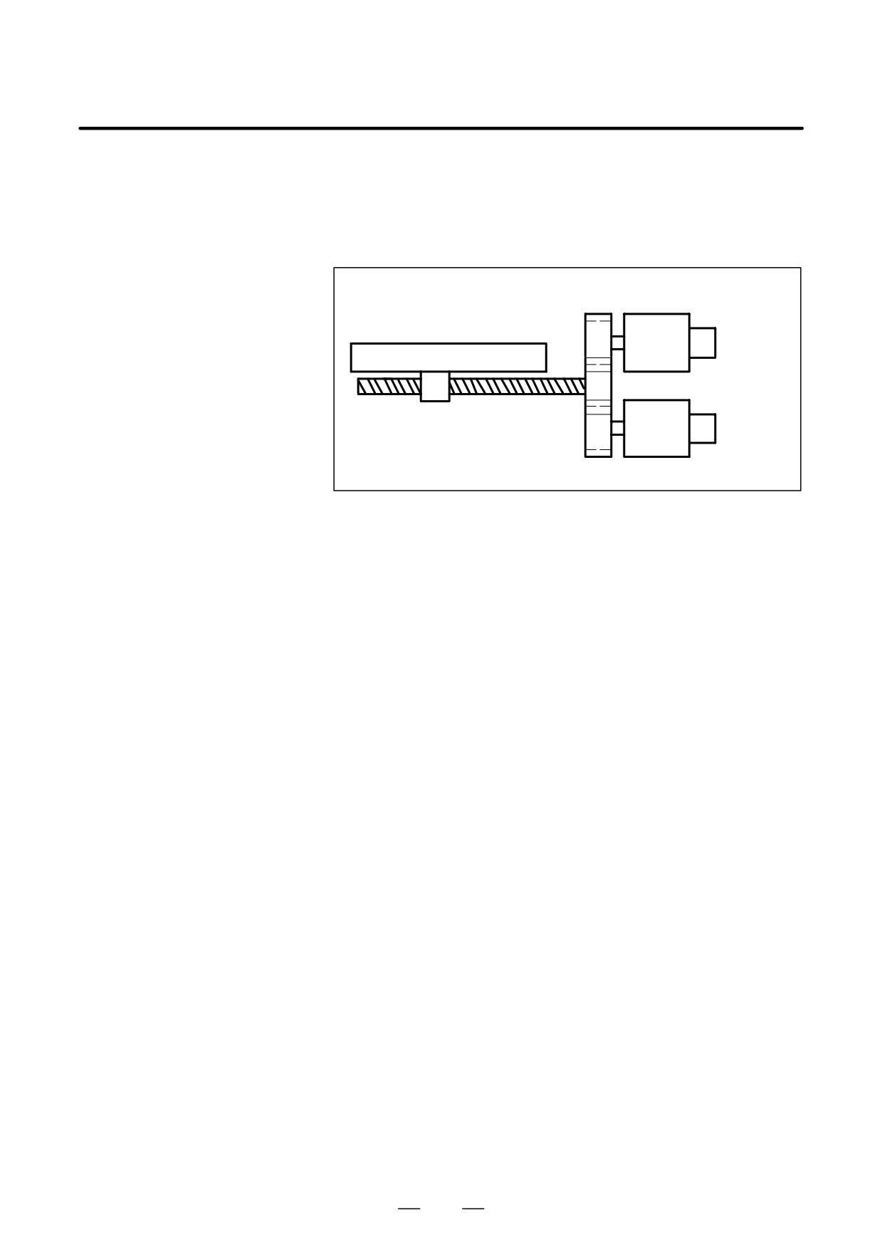
When enough torque for driving a large table cannot be produced by only
20.4
one motor, two motors can be used for movement along a single axis.
TANDEM CONTROL
Positioning is performed by the main motor only. The submotor is used
only to produce torque. With this tandem control function, the torque
produced can be doubled.
Main motor
Table
Ball screw
Submotor
Fig. 20.4 (a) Example of operation
In general, the NC regards tandem control as being performed for one
axis. However, for servo parameter management and servo alarm
monitoring, tandem control is regarded as being performed for two axes.
For details, refer to the relevant manual published by the machine tool
builder.
536
B-63534EN/02
PROGRAMMING
20. AXIS CONTROL FUNCTIONS
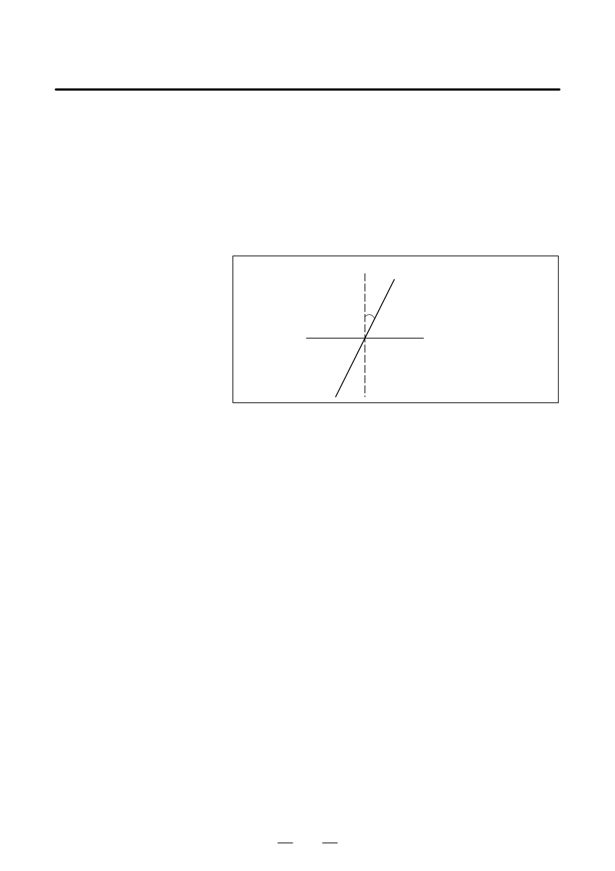
When the angular axis makes an angle other than
90° with the
20.5
perpendicular axis, the angular axis control function controls the distance
ANGULAR AXIS
traveled along each axis according to the inclination angle. For the
CONTROL/
ordinary angular axis control function, the angular axis is always the
Y-axis and the perpendicular axis is always the Z-axis. For angular axis
ARBITRARY
control B, however, arbitrary axes can be specified as the angular and
ANGULAR AXIS
perpendicular axes, using parameters. A program, when created, assumes
that the angular axis and perpendicular axis intersect at right angles.
CONTROL
However, the actual distance traveled is controlled according to an
inclination angle.
+Y
Program coordinate system
+Y Coordinate system actually used
(Angular axis)
θ
+Z (Perpendicular axis)
θ : Inclination angle
Explanations
When the angular axis is the Y-axis and the perpendicular axis is the
Z-axis, the amount of travel along each axis is controlled according to the
formulas shown below.
The distance traveled along the Y-axis is determined by the following
formula:
Ya=Yp/cosθ
The distance traveled along the Z-axis is corrected by the inclination of
the Y-axis, and is determined by the following formula:
Za=Zp-Yp*tanθ
The speed component along the Y-axis is determined by the following
formula:
Fa=Fp/cosθ
Ya, Za, Fa : Actual distance and speed
Yp, Zp, Fp : Programmed distance and speed
D Method of use
The angular and perpendicular axes for which angular axis control is to
be applied must be specified beforehand, using parameters (No. 8211 and
8212).
Parameter AAC (No. 8200#0) enables or disables the inclined axis
control function. If the function is enabled, the distance traveled along
each axis is controlled according to an inclination angle parameter (No.
8210).
Parameter AZR (No. 8200#2) enables angular axis manual reference
point return only with a distance along the angular axis.
By setting the normal axis/angular axis control invalid signal NOZAGC
D Invalidity of normal axis
to 1, slanted axis control only for the angular axis can be available.
In this time the angular axis are converted to those along the slanted
coordinate system without affecting commands to normal axis.
537

20. AXIS CONTROL FUNCTIONS
PROGRAMMING
B-63534EN/02
D Absolute and relative
An absolute and a relative position are indicated in the programmed
position display
Cartesian coordinate system.
D Machine position display
A machine position indication is provided in the machine coordinate
system where an actual movement is taking place according to an
inclination angle. However, when inch/metric conversion is performed,
a position is indicated which incorporates inch/metric conversion applied
to the results of inclination angle operation.
WARNING
1
After angular axis control parameter setting, be sure to
perform manual reference position return operation.
2
If once manual reference position return has been
performed along the angular axis, also perform manual
reference position return along the perpendicular axis.
P/S alarm No.090 is issued when an attempt is made to
manually return to the reference position along the
perpendicular axis although the angular axis is not on the
reference point.
3
Once the tool has been moved along the angular axis when
perpendicular/angular axis control disable signal NOZAGC
has been set to 1, manual reference position return must be
performed.
4
Before attempting to manually move the tool along the
angular and perpendicular axes simultaneously, set
perpendicular/angular axis control disable signal NOZAGC
to 1.
NOTE
1
For arbitrary angular axis control B, if the same axis number
has been specified in both parameters No.8211 and 8212,
or if a value outside the valid data range has been specified
for either parameter, the angular and perpendicular axes
become the following:
Angular axis: Second axis
Perpendicular axis: Third axis
2
If an inclination angle close to 0° or ±90° is set, an error can
occur. (A range from ±20° to ±60° should be used.)
3
Before a perpendicular axis reference position return check
(G27) can be made, angular axis reference position return
operation must be completed.
538

B-63534EN/02
PROGRAMMING
20. AXIS CONTROL FUNCTIONS
20.6
When contour grinding is performed, the chopping function can be used
to grind the side face of a workpiece. By means of this function, while
CHOPPING
the grinding axis (the axis with the grinding wheel) is being moved
FUNCTION
vertically, a contour program can be executed to instigate movement
(G80, G81.1)
along other axes.
In addition, a servo delay compensation function is supported for
chopping operations. When the grinding axis is moved vertically at high
speed, a servo delay and acceleration/deceleration delay occur. These
delays prevent the tool from actually reaching the specified position. The
servo delay compensation function compensates for any displacement by
increasing the feedrate. Thus, grinding can be performed almost up to the
specified position.
There are two types of chopping functions: that specified by
programming, and that activated by signal input. For details of the
chopping function activated by signal input, refer to the manual provided
by the machine tool builder.
Format
G81.1 Z__ Q__ R__ F__ ;
Z : Upper dead point
(For an axis other than the Z-axis, specify the axis address.)
Q: Distance between the upper dead point and lower dead point
(Specify the distance as an incremental value, relative to the
upper dead point.)
R : Distance from the upper dead point to point R
(Specify the distance as an incremental value, relative to the
upper dead point.)
F : Feedrate during chopping
G80; Cancels chopping
Explanations
D Chopping activated by
Before chopping can be started, the chopping axis, reference position,
signal input
upper dead point, lower dead point, and chopping feedrate must be set
using the parameter screen (or the chopping screen).
For details, refer to the manual provided by the machine tool builder.
D Chopping feedrate
From the start of chopping to point R, the tool moves at the rapid traverse
(feedrate of movement to
rate (specified by parameter No. 1420).
point R)
The override function can be used for either the normal rapid traverserate
or chopping feedrate, one of which can be selected by setting CPRPD (bit
0 of parameter No. 8360).
When the chopping feedrate is overridden, settings between 110% and
150% are clamped to 100%.
D Chopping feedrate
Between point R, reached after the start of chopping, and the point where
(feedrate of movement
the chopping is canceled, the tool moves at the chopping feedrate
from point R)
(specified by parameter No. 8374).
539
20. AXIS CONTROL FUNCTIONS
PROGRAMMING
B-63534EN/02
The chopping feedrate is clamped to the maximum chopping feedrate (set
with parameter No. 8375) if the specified feedrate is greater than the
maximum chopping feedrate.
The feedrate can be overridden by 0% to 150% by applying the chopping
feedrate override signal.
D Setting chopping data
Set the following chopping data:
D Chopping axis:
Parameter No. 8370
D Reference point (point R):
Parameter No. 8371
D Upper dead point:
Parameter No. 8372
D Lower dead point:
parameter No. 8373
D Chopping feedrate:
Parameter No. 8374
D Maximum chopping feedrate: Parameter No. 8375
All data items other than the chopping axis and maximum chopping
feedrate can be set on the chopping screen.
For details of how to set chopping data on the chopping screen, refer to
III 11.4.13 Displaying and Setting Chopping Data.
D Chopping after the upper
When the upper dead point or lower dead point is changed while chopping
dead point or lower dead
is being performed, the tool moves to the position specified by the old
point has been changed
data. Then, chopping is continued using the new data.
While chopping is being performed, data can be changed only on the
chopping screen. Changing the data on the parameter screen has no effect
on the current chopping operation.
When movement according to the new data starts, the servo delay
compensation function stops the servo delay compensation for the old
data, and starts the servo delay compensation for the new data.
The following describes the operations performed after the data has been
changed.
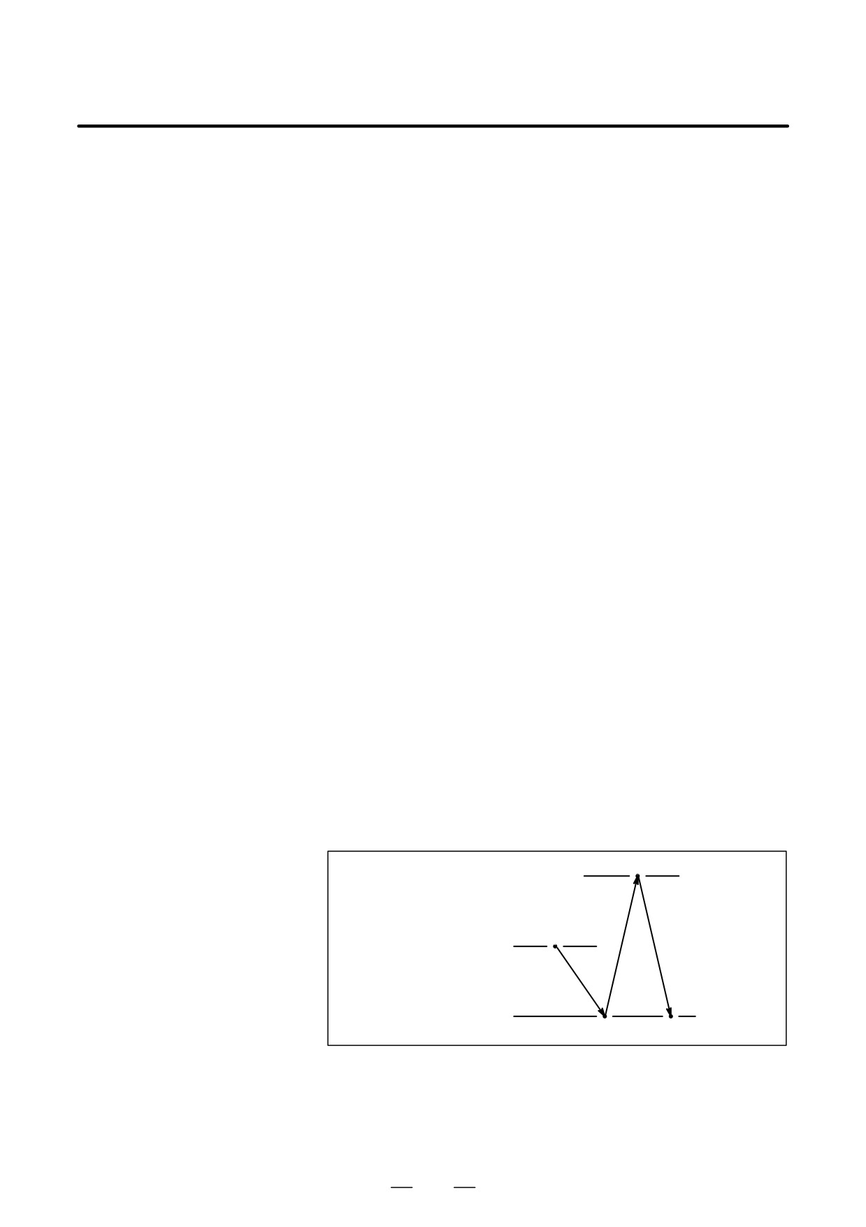
(1) When the upper dead point is changed during movement from the
upper dead point to the lower dead point
New upper dead point
Previous upper dead point
Previous lower dead point
The tool first moves to the lower dead point, then to the new upper
dead point.
Once movement to the lower dead point has been completed, the
previous servo delay compensation is set to 0, and servo delay
compensation is performed based on the new data.
540
B-63534EN/02
PROGRAMMING
20. AXIS CONTROL FUNCTIONS
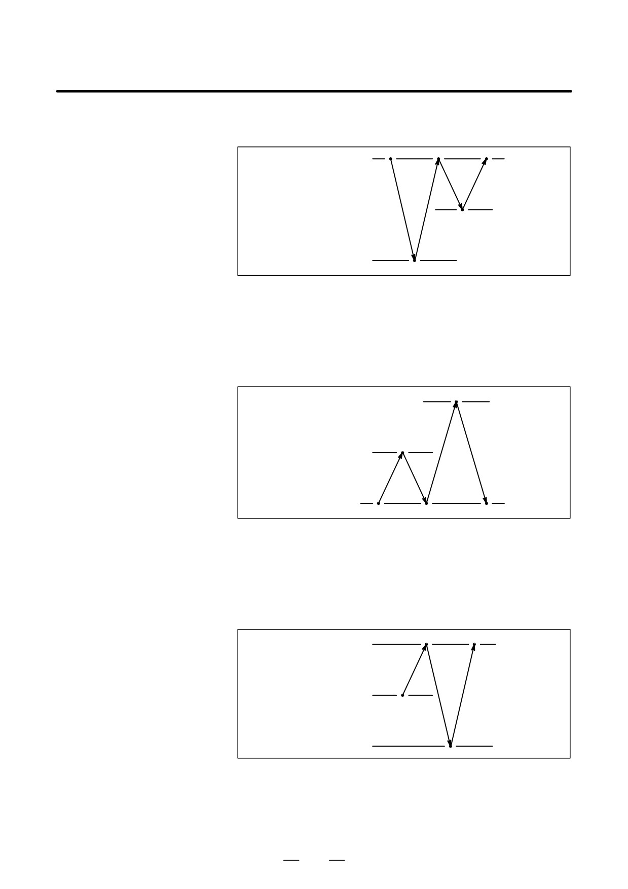
(2) When the lower dead point is changed during movement from the
upper dead point to the lower dead point
Previous upper dead point
New lower dead point
Previous lower dead point
The tool first moves to the previous lower dead point, then to the upper
dead point, and finally to the new lower dead point.
Once movement to the upper dead point has been completed, the
previous servo delay compensation is set to 0, and servo delay
compensation is performed based on the new data.
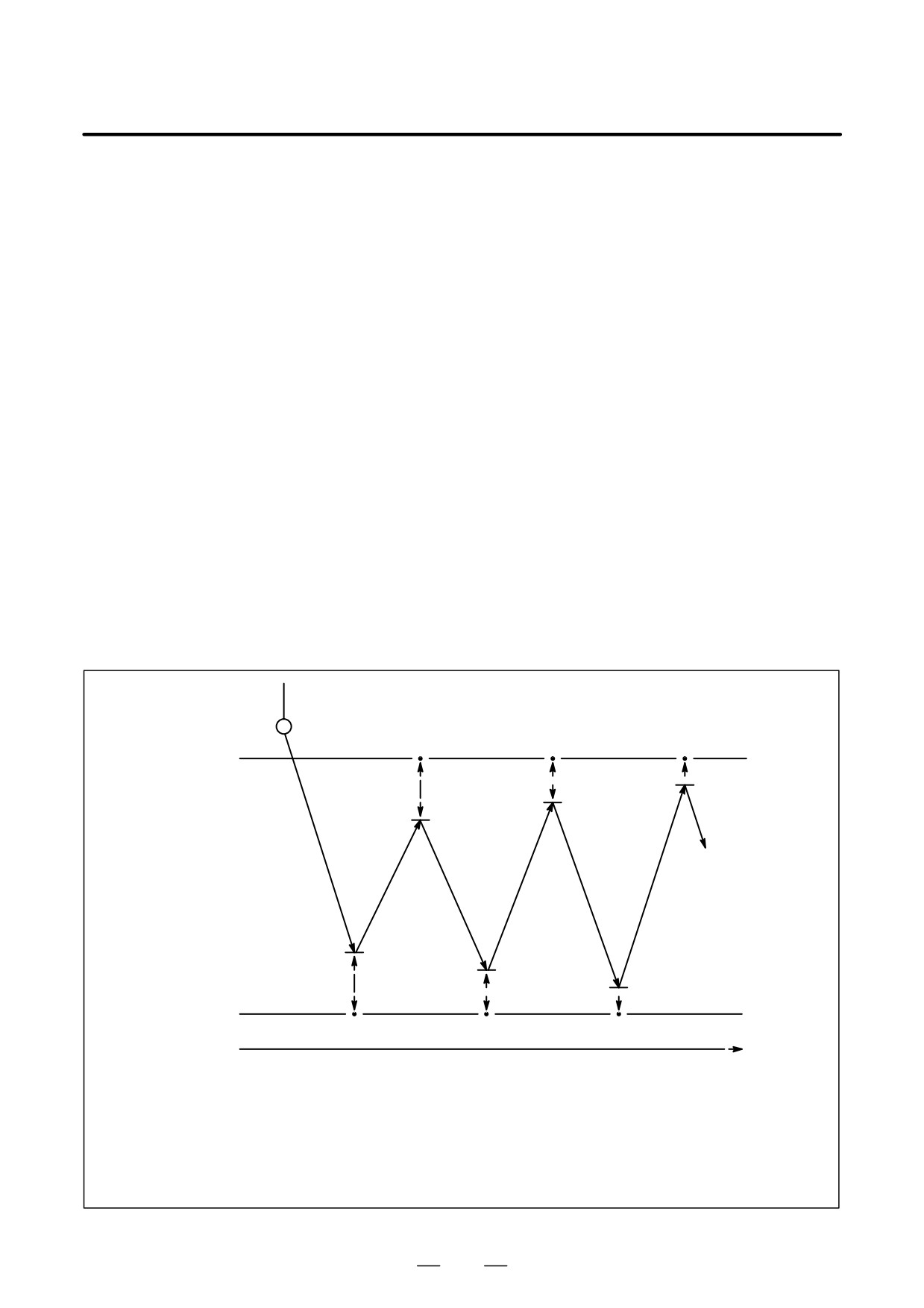
(3) When the upper dead point is changed during movement from the
lower dead point to the upper dead point
New upper dead point
Previous upper dead point
Previous lower dead point
The tool first moves to the previous upper dead point, then to the lower
dead point, and finally to the new upper dead point.
Once movement to the lower dead point has been completed, the
previous servo delay compensation is set to 0, and servo delay
compensation is performed based on the new data.
(4) When the lower dead point is changed during movement from the
lower dead point to the upper dead point
Previous upper dead point
Previous lower dead point
New lower dead point
The tool first moves to the upper dead point, then to the new lower
dead point.
Once movement to the upper dead point has been completed, the
previous servo delay compensation is set to 0, and servo delay
compensation is performed based on the new data.
541
20. AXIS CONTROL FUNCTIONS
PROGRAMMING
B-63534EN/02
D Servo delay
When high-speed chopping is performed with the grinding axis, a servo
compensation function
delay and acceleration/deceleration delay occur. These delays prevent the
tool from actually reaching the specified position. The control unit
measures the difference between the specified position and the actual tool
position, and automatically compensates for the displacement of the tool.
To compensate for this displacement, an amount of travel equal to the
distance between the upper and lower dead points, plus an appropriate
compensation amount, is specified. When a chopping command is
specified, the feedrate is determined so that the chopping count per unit
time equals the specified count. When the difference between the
displacement of the tool from the upper dead point and the displacement
of the tool from the lower dead point becomes smaller than the setting of
parameter No. 8377, after the start of chopping, the control unit performs
compensation.
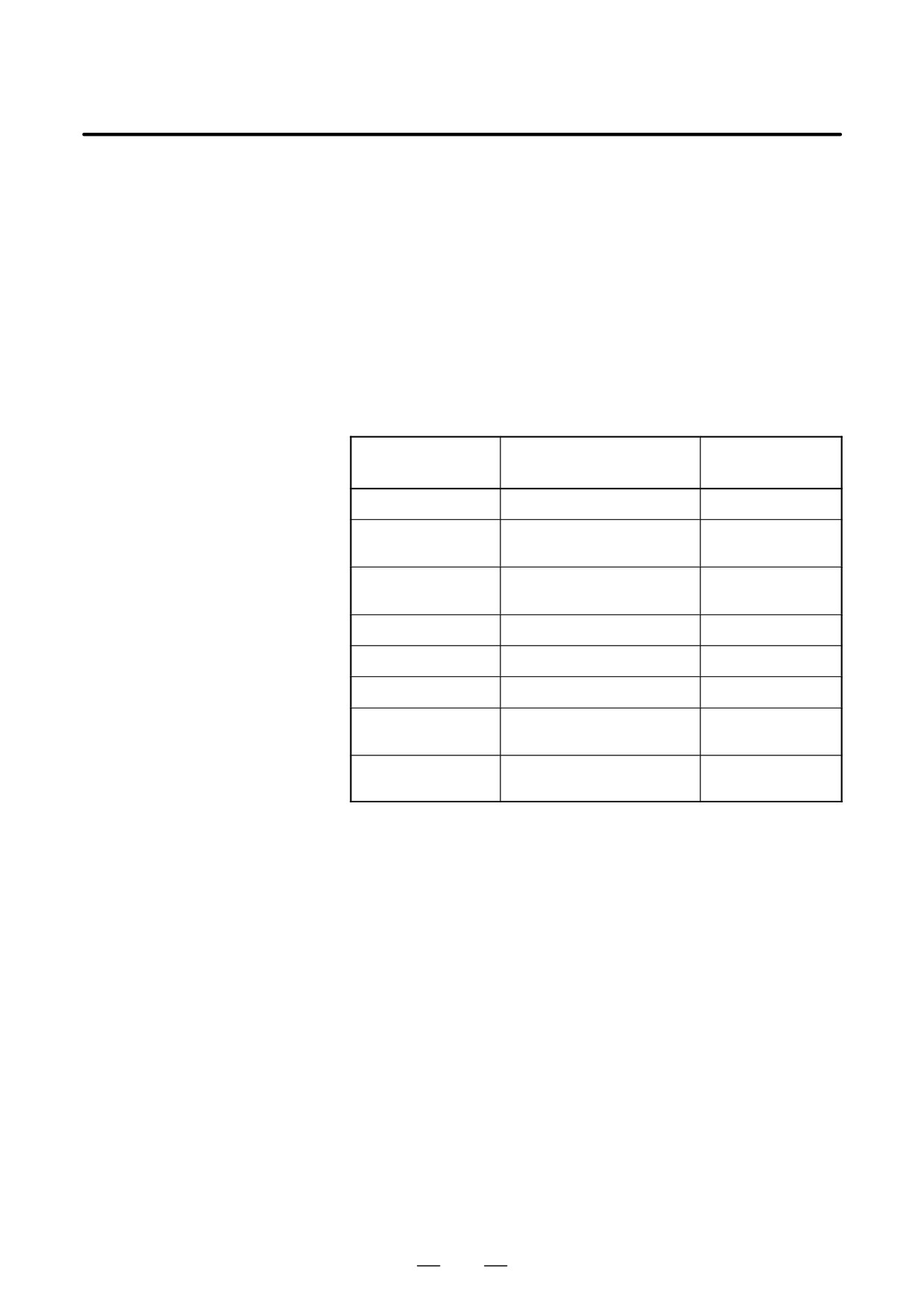
When compensation is applied, the chopping axis moves beyond the
specified upper dead point and lower dead point, and the chopping
feedrate increases gradually.
When the difference between the actual machine position and the
specified position becomes smaller than the effective area setting
(parameter No. 1826), the control unit no longer applies compensation,
allowing the tool to continue moving at its current feedrate.
A coefficient for the compensation amount for the displacement
generated by the servo delay incurred by chopping and the delay incurred
during acceleration/deceleration can be specified in parameter No. 8376.
Point R
Upper dead point
L2
L4
L6
L1
L3
L5
Lower dead point
Time
Displacement between the tool and the upper dead point: L2, L4, L6
Displacement between the tool and the lower dead point: L1, L3, L5
Compensation starts when:
| L3 - L2 | < (parameter No. 8377)
When the following condition is satisfied, compensation is no longer applied,
and the tool continues to move at its current feedrate:
| L6 | < effective area setting (parameter No. 1826)
542
B-63534EN/02
PROGRAMMING
20. AXIS CONTROL FUNCTIONS
D Mode switching during
If the mode is changed during chopping, chopping does not stop. In
chopping
manual mode, the chopping axis cannot be moved manually. It can,
however, be moved manually by means of the manual interrupt.
D Reset during chopping
When a reset is performed during chopping, the tool immediately moves
to point R, after which chopping mode is canceled.
If an emergency stop or servo alarm occurs during chopping, mode is
canceled, and the tool stops immediately.
D Stopping chopping
The following table lists the operations and commands that can be used
to stop chopping, the positions at which chopping stops, and the operation
performed after chopping stops:
Operation after
Operation/command
Stop position
chopping stops
G80
Point R
Canceled
CHPST: “0”
The tool moves to the lower
Canceled
dead point, then to point R.
*CHLD: “0”
Point R
Restart after *CHLD
goes “1”
Reset
Point R
Canceled
Emergency stop
The tool stops immediately.
Canceled
Servo alarm
The tool stops immediately.
Canceled
P/S alarm
The tool moves to the lower
Canceled
dead point, then to point R.
OT alarm
The tool moves from the up-
Canceled
per or lower point to point R.
D Background editing
When an alarm or battery alarm is issued during background editing, the
tool does not stop at point R.
D Single block signal
Even when single block signal SBK is input during chopping, chopping
continues.
Limitations
D Workpiece coordinate
While chopping is being performed, do not change the workpiece
system
coordinate system for the chopping axis.
D PMC axis
When the chopping axis is selected as the PMC axis, chopping is not
started.
D Mirror image
While chopping is being performed, never attempt to apply the mirror
image function about the chopping axis.
D Move command during
If a move command is specified for the chopping axis while chopping is
chopping
being performed, a P/S 5050 alarm is issued.
D Advanced preview
This function does not support the advanced preview control function.
control
543
20. AXIS CONTROL FUNCTIONS
PROGRAMMING
B-63534EN/02
D Program restart
When a program contains G codes for starting chopping (G81.1) and
stopping chopping (G80), an attempt to restart that program results in a
P/S 5050 alarm being output.
When a program that does not include the chopping axis is restarted
during chopping, the coordinates and amount of travel set for the
chopping axis are not affected after the restart of the program.
Examples
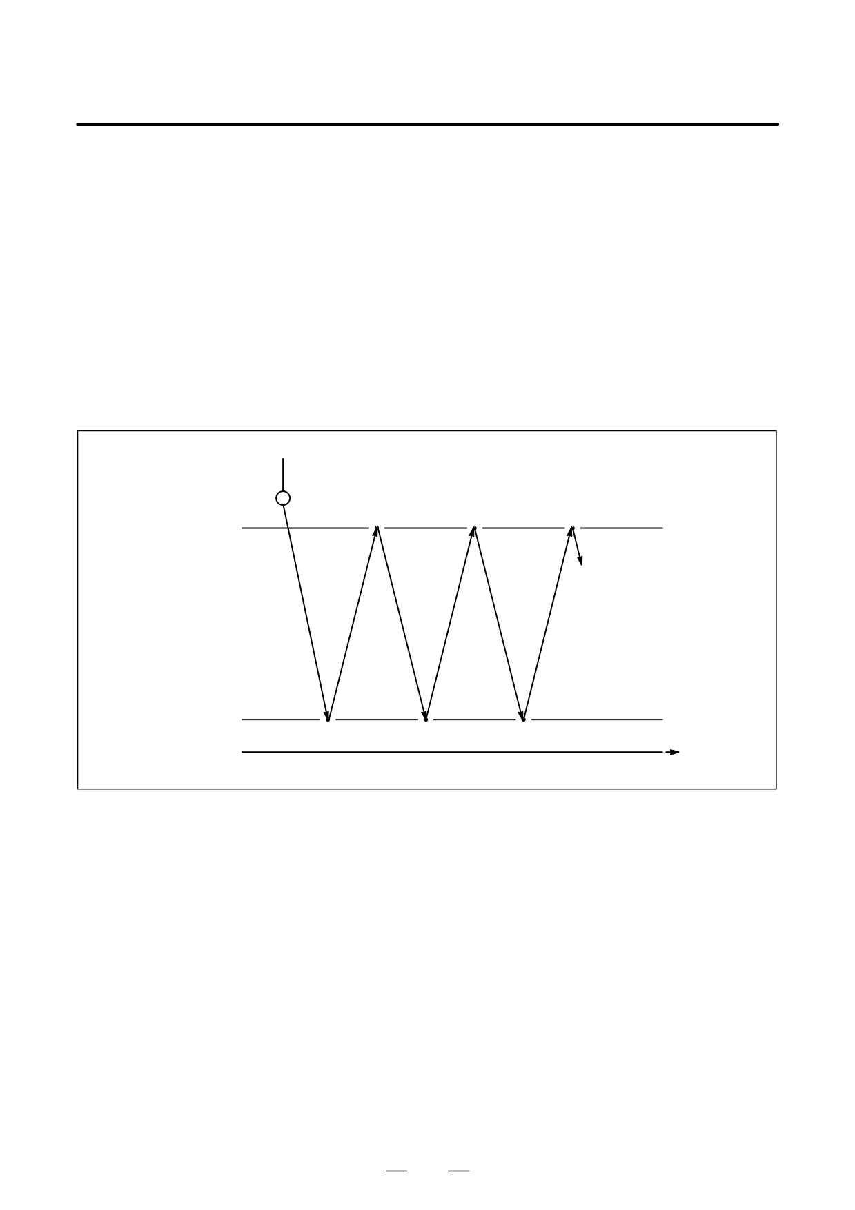
G90 G81.1 Z100. Q-25. R10. F3000 ;
D Perform rapid traverse to position the tool to Z110. (point R).
D Then, perform reciprocating movement along the Z-axis between
Z100. (upper dead point) and Z75. (lower dead point) at 3000
mm/min. Chopping override is enabled.
Point R
(Z110. )
Upper dead point
(Z100. )
Lower dead point
(Z75. )
Time
To cancel chopping, specify the following command:
G80 ;
D The tool stops at point R.
544
B-63534EN/02
PROGRAMMING
20. AXIS CONTROL FUNCTIONS
20.7
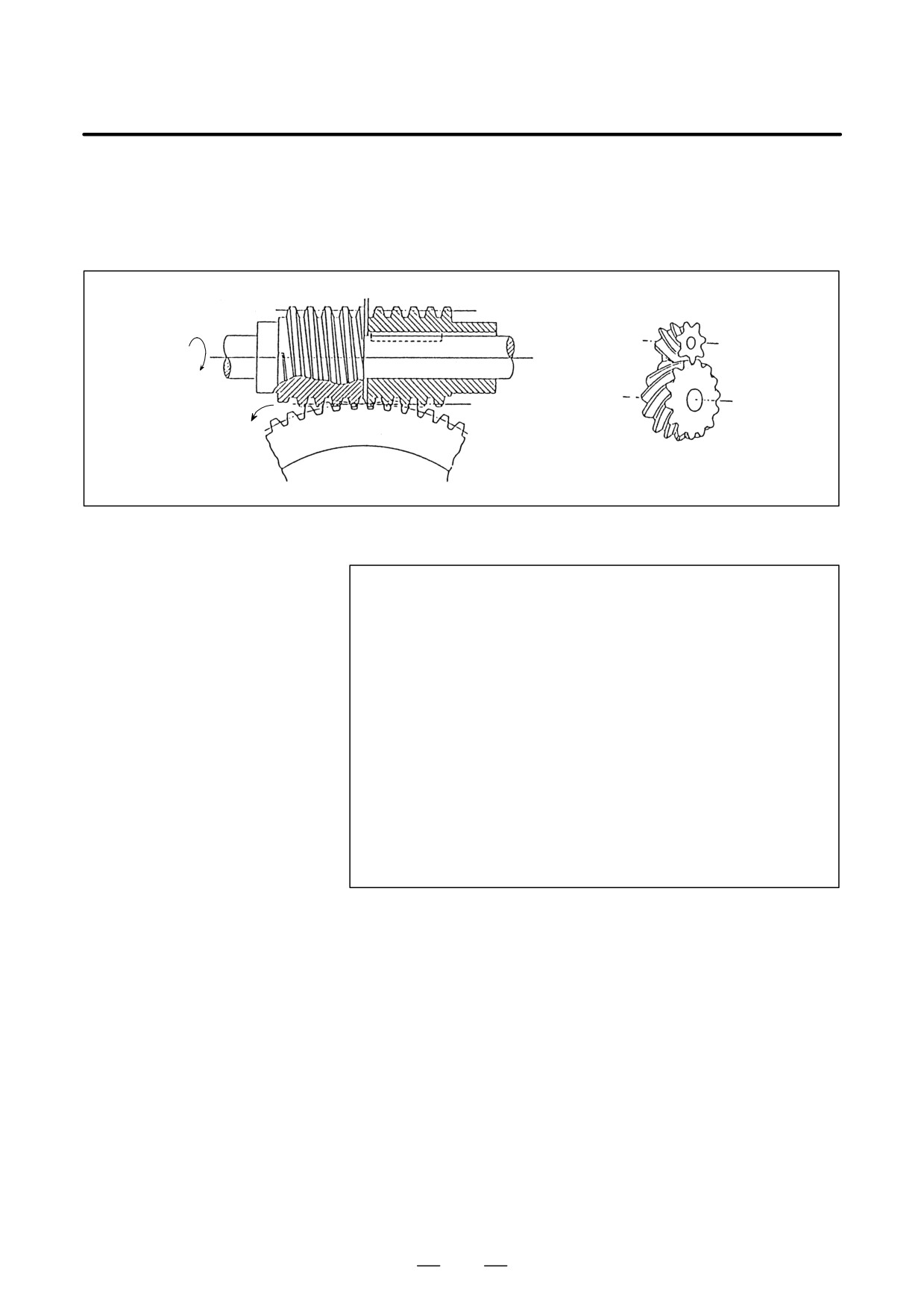
Gears can be cut by turning the workpiece (C-axis) in sync with the
rotation of the spindle (hob axis) connected to a hob.
HOBBING MACHINE
Also, a helical gear can be cut by turning the workpiece (C-axis) in sync
FUNCTION (G80, G81)
with the motion of the Z-axis (axial feed axis).
Helical gear
Spindle
Hob
C-axis
Gear material
Format
G81 T_ L_ Q_ P_ ;
T : Number of teeth (Specifiable range: 1 to 5000)
L : Number of hob threads (Specifiable range: 1 to 20 with a sign)
⋅ The sign of L specifies the direction of rotation of the C-axis.
⋅ If L is positive, the C-axis rotates in the positive direction (+).
⋅ If L is negative, the C-axis rotates in the negative direction (-).
Q: Module or diametral pitch
For metric input, specify a module.
(Unit:
0.00001 mm, Specifiable range: 0.01 to 25.0 mm)
For inch input, specify a diametral pitch.
(Unit:
0.00001 inch-1, Specifiable range: 0.01 to 250.0 inch-1)
P : Gear helix angle
(Unit:
0.0001 deg, Specifiable range: -90.0 to +90.0 deg)
P and Q must be specified when a helical gear is to be cut.
G80; Cancels synchronization between the hob axis and C-axis.
Explanations
D Setting the C-axis
The C-axis (workpiece) is usually the fourth axis. However, any axis can
be set as the C-axis by setting the corresponding parameter appropriately
(parameter No. 7710).
D Maintaining the
The synchronization status is maintained provided:
synchronization status
⋅
The interlock signal for the C-axis is turned on.
⋅
The feed hold state exists.
545
20. AXIS CONTROL FUNCTIONS
PROGRAMMING
B-63534EN/02
D Releasing the
Synchronization between the hob axis and C-axis can also be canceled
synchronization status
when:
⋅
The power is turned off.
⋅
An emergency stop or servo alarm occurs.
⋅
A reset (external reset signal, reset & rewind signal, or reset key on the
MDI panel) is issued.
By setting bit 0 (HBR) of parameter No. 7700, the release of the
synchronization status by a reset can be suppressed.
D Helical gear
When a helical gear is to be cut, compensation for the C-axis is needed
compensation
according to the amount of travel along the Z-axis (third axis) (axial feed)
and gear helix angle.
Helical gear compensation is performed by adding compensation pulses,
calculated using the formula below, to the C-axis which is synchronized
with the hob axis:
Z sin (P)
Compensation angle =
360 (For metric input)
π T Q
or
Z Q sin (P)
Compensation angle =
360 (For inch input)
π T
where
Compensation angle : Signed absolute value (deg)
Z
: Amount of travel along the Z-axis after the
specification of G81 (mm or inches)
Total amount of travel along the Z-axis in both
automatic and manual modes
P
: Signed gear helix angle (deg)
T
: Number of teeth
Q : Module (mm) or diametral pitch (inch-1)
The values of P, T, and Q must be programmed.
546
B-63534EN/02
PROGRAMMING
20. AXIS CONTROL FUNCTIONS
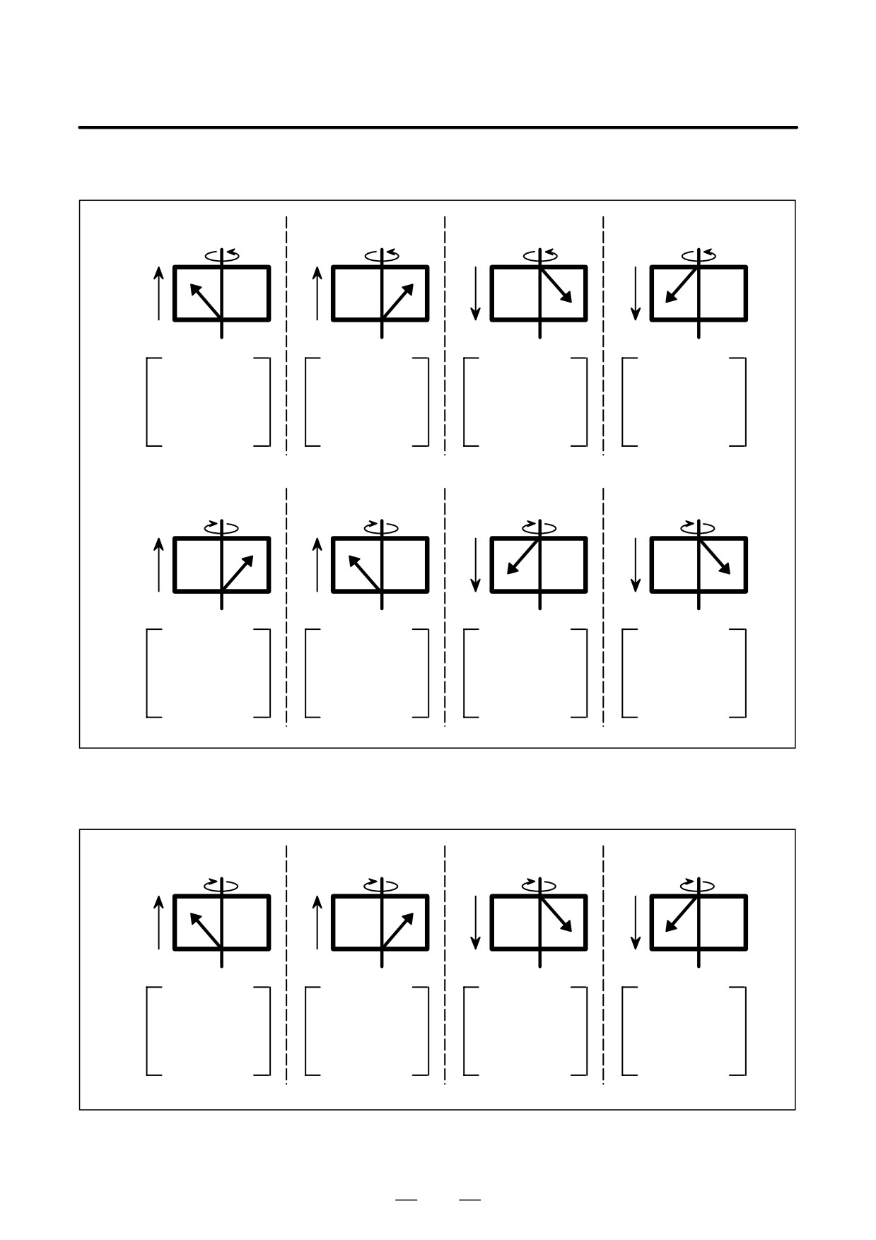
D Direction of helical gear
1 When bit 2 (HDR) of parameter No. 7700 = 1
compensation
(a)
(b)
(c)
(d)
+Z
+C
+Z
+C
+Z
+C
+Z
+C
- Z
- Z
- Z
- Z
C : +
C : +
C : +
C : +
Z : +
Z : +
Z : -
Z : -
P : +
P : -
P : +
P : -
Compensation
Compensation
Compensation
Compensation
direction
:
+
direction
:
-
direction
:
-
direction
:
+
(e)
(f)
(g)
(h)
+Z
- C
+Z
- C
+Z
- C
+Z
- C
- Z
- Z
- Z
- Z
C : -
C : -
C : -
C : -
Z : +
Z : +
Z : -
Z : -
P : +
P : -
P : +
P : -
Compensation
Compensation
Compensation
Compensation
direction
:
-
direction
:
+
direction
:
+
direction
:
-
2 When bit 2 (HDR) of parameter No. 7700 = 0 (Items (a) to (d) are the
same as for 1.)
(e)
(f)
(g)
(h)
+Z
- C
+Z
- C
+Z
- C
+Z
- C
- Z
- Z
- Z
- Z
C : -
C : -
C : -
C : -
Z : +
Z : +
Z : -
Z : -
P : +
P : -
P : +
P : -
Compensation
Compensation
Compensation
Compensation
direction
:
+
direction
:
-
direction
:
-
direction
:
+
547
20. AXIS CONTROL FUNCTIONS
PROGRAMMING
B-63534EN/02
D Setting the helical gear
The Z-axis (axial feed axis) is usually the third axis. However, any axis
axial feed axis
can be set as the Z-axis by setting the corresponding parameter
appropriately (parameter No. 7709).
D C-axis servo delay
The servo delay is proportional to the speed of the hob axis. Therefore,
compensation (G82, G83,
in a cycle where rough machining and finish machining are performed at
G84)
different hob axis speeds, compensation for the servo delay is required.
The servo delay is calculated as follows:
Fc
1
E= {(
)
(
+C:M+L) +Sup} N
60
Ks
where
E
: C-axis servo delay compensation
(deg)
Fc
: C-axis speed when G83 is specified
(deg/min)
Ks
: Servo loop gain (LPGIN of parameter No. 1825)
(sec-1)
C
: Delay incurred in the CNC
(sec)
M
: Delay compensation magnification 1 in the CNC
(SVCMP1 of parameter No. 7715)
L
: Delay incurred by smoothing, as specified by
parameter No. 7701
(sec)
Sup
: Remaining pulse error caused by acceleration/
deceleration
(deg)
N
: C-axis servo delay compensation magnification 2
(SVCMP2 of parameter No. 7714)
When the hob axis speed is changed, C-axis servo delay compensation
is performed using the following two methods:
S Compensation is specified both before and after the speed is
changed. Each time G83 is specified, compensation for the delay
at that time is applied.
S Before the speed is changed, the servo delay is recorded. After the
speed is changed, compensation for the difference between the
recorded delay and that observed when the command is specified
is performed.
The latter method, in which the compensation before speed change is
recorded, can be used by setting bit 5 (DLY) of parameter No. 7701 to 1.
This method, in comparison with that where the amount of compensation
is not recorded, offers the advantage of processing being possible at
higher speeds.
548
B-63534EN/02
PROGRAMMING
20. AXIS CONTROL FUNCTIONS
⋅
Method in which compensation for the delay when a command is
specified is performed (G82, G83)
G82: Cancels C-axis servo delay compensation.
G83: Executes C-axis servo delay compensation.
(Example)
G81 T__ L__
;
· · · Starts synchronization.
M03 S100
;
· · · Rotates the hob axis.
G04 P2000 ;
· · · Dwell to assure constant hob axis rotation.
G01 G83
F__
;
· · · Performs C-axis delay compensation.
G01 X__
F__
;
·
·
G82 ;
· · · Cancels C-axis servo delay.
S200 ;
· · · Changes the speed.
G04 P2000 ;
· · · Dwell to assure constant hob axis rotation.
G01 G83
F__
;
· · · Performs C-axis delay compensation.
⋅
Method in which the delay before change is recorded (G82, G83,
G84)
G82: Cancels C-axis servo delay compensation.
G83: Performs compensation for the difference between the C-axis
servo delay, observed when G83 is specified, and the delay
recorded by G84.
G84: Records the C-axis servo delay observed when G84 is specified.
(The recorded value remains as is until G81 is specified or
another G84 is specified.)
(Example)
G81 T__ L__
;
· · · Starts synchronization.
M03 S100 ;
· · · Rotates the hob axis.
G04 P2000 ;
· · · Dwell to assure constant hob axis rotation.
G84 ;
· · · Records the C-axis servo delay at the
current speed.
G01 X__ F__
;
·
·
·
S200
;
· · · Changes the speed.
G04 P2000 ;
· · · Dwell to assure constant hob axis rotation
G01 G83
F__;
· · · Performs C-axis servo delay compensation.
⋅
Notes
S Specify the G83 block in G01 mode. Also, specify a feedrate using
the F code.
S Once G83 has been specified, another G83 command cannot be
specified until compensation is canceled by specifying G82, or
C-axis synchronization is canceled.
S Specify G83 once a constant hob axis rotation speed has been
achieved.
549