FANUC Series 16i/160i/160is-MB, Series 18i/180i/180is-MB5, Series 18i/180i/180is-MB. Operator's Manual - page 18

19. HIGH SPEED CUTTING FUNCTIONS
PROGRAMMING
B-63534EN/02
(2) Override near the base circle
In a part near the base circle where the change in the curvature of the
involute curve is relatively significant, cutting at the feedrate as specified
in the program may put a heavy load on the cutter, resulting in a rough
cutting surface. This function automatically decelerates the movement of
the tool in a part near the base circle where the change in the curvature of
the involute curve is significant according to the settings of parameters to
decrease the load on the cutter for a fine cutting surface.
If the radius of curvature at the cutting point reaches a value within the
range specified in parameter (Rlmt1) to (Rlmt5), the corresponding
override listed below is applied:
When Rlmt1 > Rcp"RofsyRlmt2:
100 * OVR2
OVRb +
(Rcp " Rofs * Rlmt2) ) OVR2
Rlmt1 * Rlmt2
When Rlmt2 > Rcp"RofsyRlmt3:
OVRb +OVR2*OVR3
(Rcp " Rofs * Rlmt3) ) OVR3
Rlmt2 * Rlmt3
When Rlmt3 > Rcp"RofsyRlmt4:
OVRb +OVR3*OVR4
(Rcp " Rofs * Rlmt4) ) OVR4
Rlmt3 * Rlmt4
When Rlmt4 > Rcp"RofsyRlmt5:
OVRb +OVR4*OVR5
(Rcp " Rofs * Rlmt5) ) OVR5
Rlmt4 * Rlmt5
Set Rlmt1 to Rlmt5 and OVR2 to OVR5 in parameter Nos. 5611 to 5615
and 5616 to 5619, respectively. Rcp ( Rofs means Rcp + Rofs for inward
offset or Rcp - Rofs for outward offset.
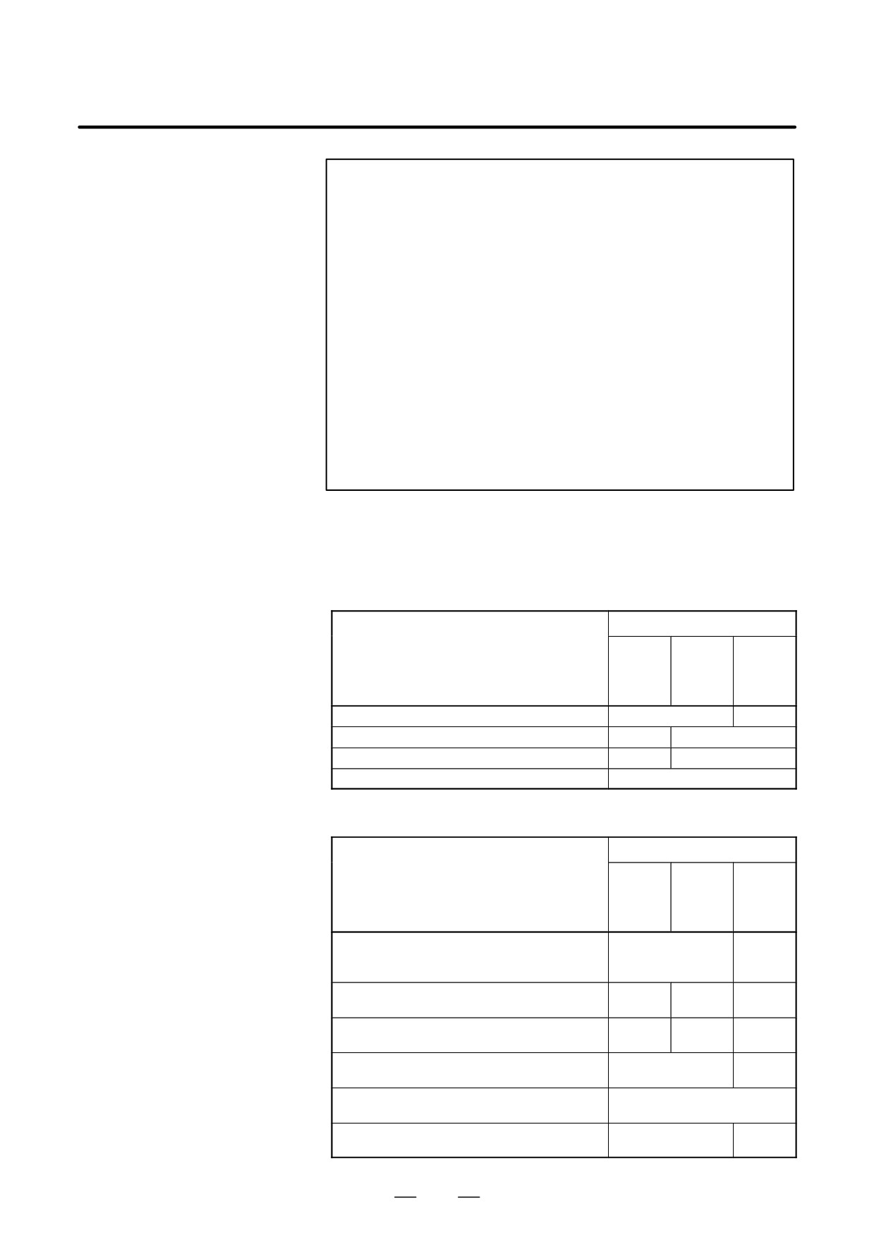
100
OVR2
OVR3
OVR4
OVR5
OVRlo
Rlmt5
Rlmt4
Rlmt3
Rlmt2
Rlmt1
If the calculated override is lower than the lower limit set in the
corresponding parameter, it is clamped to the lower override limit.
490
B-63534EN/02
PROGRAMMING
19. HIGH SPEED CUTTING FUNCTIONS
NOTE
1
When the override near the base circle is enabled, the
override for inward offset in cutter compensation is disabled.
These overrides cannot be enabled simultaneously.
2
When the distance from the center of the base circle to the
start point is the same as that from the center of the base
circle to the end point, that is, for a circle, circular
interpolation is used. For this reason, no automatic override
is applied.
3
If there is an end point error, the feedrate is not guaranteed.
4
If there is an end point error, the remaining distance required
for acceleration/deceleration before interpolation may not
be obtained exactly. In this case, alarm 242 occurs.
5
For other restrictions, refer to the operator’s manual.
6
In the AI nano contour control mode, involute interpolation
cannot be specified.
D Corresponding
In the following tables, AI control means the AI contour control/AI nano
parameter numbers in
contour control mode.
the normal mode,
(1) Parameters related to linear acceleration/deceleration before
advanced preview
interpolation
control mode, and AI
contour control/AI nano
Parameter number
contour control mode
Ad-
Parameter
vanced
AI
Normal
preview
contour
control
Acceleration/deceleration type (A or B)
FWB/1602#0
None
Parameter 1 for setting the acceleration
1630
1770
Parameter 2 for setting the acceleration
1631
1771
Feedrate at which an overtravel alarm occurs
1784
(2) Parameters related to automatic corner deceleration
Parameter number
Ad-
Parameter
vanced
AI
Normal
preview
contour
control
Method for determining whether to perform
CSD/1602#4
None
automatic corner deceleration (angle/fee-
drate difference)
Lower feedrate limit (control according to the
1778
1777
None
angle)
Angle at which automatic corner deceleration
1740
1779
None
is performed (control according to the angle)
Allowable feedrate difference for all axes
1780
None
(control according to the feedrate difference)
Allowable feedrate difference for each axis
1783
(control according to the feedrate difference)
Acceleration/deceleration type
FWB/1602#0
None
(Type A/Type B)
491

19. HIGH SPEED CUTTING FUNCTIONS
PROGRAMMING
B-63534EN/02
(3) Parameter related to feedrate clamping by acceleration
Parameter number
Ad-
Parameter
vanced
AI
Normal
preview
contour
control
Parameter for determining the allowable ac-
None
1785
celeration
(4) Parameters related to feedrate clamping by arc radius
Parameter number
Ad-
Parameter
vanced
AI
Normal
preview
contour
control
Arc radius corresponding to the upper fee-
1731
drate limit
Upper feedrate limit at arc radius R
1730
Lower clamped feedrate limit
1732
(5) Parameters related to involute interpolation (only in the AI contour
control mode)(*1)
Parameter number
Ad-
Parameter
vanced
AI
Normal
preview
contour
control
Initial angle error limit
5610
Override near the base circle: Radius of cur-
None
5611 to
vature
5615
Override near the base circle: Override
None
5616 to
5619
Lower override limit
None
5620
(6) Other parameters
Parameter number
Ad-
Parameter
vanced
AI
Normal
preview
contour
control
Precision of radius errors in circular interpola-
PCIR1/3403#0
None
tion
Maximum cutting feedrate (common to all
1422
1431
1422
axes)
Maximum cutting feedrate (for each axis)
1430
1432
Rapid traverse movement type*
LRP/1401#1
AIR/
7054#1
LRP/
1401#1
Time constant for bell-shaped acceleration/
1621
deceleration for rapid traverse
492

B-63534EN/02
PROGRAMMING
19. HIGH SPEED CUTTING FUNCTIONS
Parameter number
Ad-
Parameter
vanced
AI
Normal
preview
contour
control
Arc radius corresponding to the upper fee-
1731
drate limit
* For AI nano-contour control, the rapid traverse movement type is not set
with a parameter, but is always linear interpolation positioning.
Alarms
Num-
Message
Description
ber
5110
IMPROPER G CODE
An unspecifiable G code was specified in
the AI contour control/AI nano contour
(G05.1 Q1 MODE)
control mode.
5111
IMPROPER MODAL
An unavailable modal G code was found
G CODE
when the AI contour control/AI nano con-
tour control mode was specified.
(G05.1 Q1)
5112
G08 CAN NOT BE
The look-ahead control command (G08)
COMMANDED
was specified in the AI contour control/AI
nano contour control mode.
(G05.1 Q1)
5114
CAN NOT ERROR IN
Intervention by manual operation was per-
MDI MODE
formed during execution of the G28, G30,
G30.1, or G53 command (linear interpola-
(G05.1 Q1)
tion type) in the AI contour control mode.
After that, automatic operation was re-
started at a position other than the stop
position.
5156
ILLEGAL AXIS
In the AI contour control/AI nano contour
OPERATION
control mode, the controlled axis selection
signal (PMC axis control) changed.
(AICC)
In the AI contour control/AI nano contour
control mode, the simple synchronous
axis selection signal changed.
5157
PARAMETER 0
The setting of the parameter for specifying
the maximum cutting feedrate (No. 1422,
(AICC)
1432, or 1420) is 0.
The setting of the parameter for specifying
acceleration/deceleration before interpola-
tion (No. 1770 or 1771) is 0.
Notes
1) This function requires the AI contour control function or AI nano
contour control function option.
When the AI contour control function option is installed, the
look-ahead control function (G08P1) can also be specified. When the
AI nano contour control function option is installed, the AI contour
control function and look-ahead control function (G08P1) can also be
specified.
493

19. HIGH SPEED CUTTING FUNCTIONS
PROGRAMMING
B-63534EN/02
2) When the total distance of blocks read in advance reaches the distance
for decelerating from the current feedrate, deceleration is started.
When look-ahead operation proceeds and the total distance of blocks
increases by termination of deceleration, acceleration is started again.
If a series of blocks with a small amount of travel are specified, the
deceleration and acceleration may be alternated, which prevents the
feedrate from being constant. In this case, specify a lower feedrate.
3) When the dry run signal is inverted from ”0” to ”1” or from ”1” to ”0”
during movement along an axis, acceleration/deceleration is
performed to the specified feedrate without deceleration to feedrate 0.
4) If a non-movement block or one-shot G code command such as G04
is found in the AI contour control/AI nano contour control mode, the
movement is decelerated and temporarily stopped in the preceding
block.
5) For acceleration/deceleration after interpolation, use linear or
bell-shaped acceleration/deceleration. Exponential acceleration/
deceleration cannot be used.
D Specifications
Axis control
f : Can be specified.
: Cannot be specified.
Name
Function
Number of controlled axes
3 to 8
To use four to eight axes, another option is required.
Number of simultaneously con-
Up to 6
trolled axes
To use three or more simultaneously controlled
axes, another option is required.
Axis name
The basic three axes are fixed to X, Y, and Z.
Other axes are any of U, V, W, A, B, and C.
Least input increment
0.001 mm, 0.001 deg, 0.0001 inch
One-tenth input increment
0.0001 mm, 0.0001 deg, 0.00001 inch
One-tenth input increment for each axis cannot be
used.
Simple synchronous control
f If the AI contour control/AI nano contour control
option is installed, however, switching between
synchronous and normal operation cannot be
performed during automatic operation (when
the automatic operation signal (OP) is set to 1)
regardless of whether the AI contour control/AI
nano contour control mode is set. In this case,
switching causes a PS213 alarm.
Twin table
Angular axis/arbitrary angular axis
control
Tandem control
f Full preloading cannot be performed, however.
Chopping
Hobbing machine function
Simple electric gear box
Learning control
Foreseeing repetition control
Inch/metric conversion
f
(*1)
(G20, G21)
Interlock
f
Interlock for each axis
f Movement along all axes stops.
To stop movement only along the interlock axis
in non-linear interpolation type positioning in
the AI contour control mode, set bit 5 (AIL) of
parameter No. 7054 to 1 and bit 4 (XIK) of pa-
rameter No. 1002 to 0.
494

B-63534EN/02
PROGRAMMING
19. HIGH SPEED CUTTING FUNCTIONS
Name
Function
Machine lock
f When the machine lock signal for each axis
(MLK1 to MLK8) is turned on or off, accelera-
tion/deceleration is not applied to the axis for
which machine lock is performed.
Stroke check before movement
Mirror image
f
Stored pitch error compensation
f
Gradientcompensation
f
Straightnesscompensation
f
Position switch
f Set bit 3 (PSF) of parameter No. 6901 to 1.
When this parameter is set to 1, the signal out-
put timing changes.
Abnormal load detection
f
Manual handle interruption
f (AI contour control)
Manual handle interruption is disabled during
switching to the AI contour control mode.
(AI nano contour control)
External pulse synchronization
Flexible synchronization
Interpolation functions
f : Can be specified.
: Cannot be specified.
Name
Function
Positioning (G00)
f
Single direction positioning (G60)
f
To perform single direction positioning in the AI
contour control/AI nano contour control mode,
set bit 4 (ADP) of parameter No. 7055 to 1.
Exact stop (G09)
f
Exact stop mode (G61)
f
Tapping mode (G63)
f
Linear interpolation (G01)
f
Circular interpolation (G02, G03)
f
(Circular interpolation for multiple quadrants is
enabled.)
Exponential interpolation
(G02.3, G03.3)
Dwell (G04)
f
(Dwell with the time in seconds or speed speci-
fied) For dwell with the speed specified, anoth-
er option is required.
Polar coordinate interpolation
(G12.1, G13.1)
Cylindrical interpolation (G07.1)
Helical interpolation (G02, G03)
f
(Circular interpolation + linear interpolation for
up to four axes)
When the helical interpolation option is
installed, linear interpolation for up to two axes
is performed. When the helical interpolation B
option is installed, linear interpolation for up to
four axes is performed. Specify the feedrate
including the helical axis in the feedrate com-
mand.
Involute interpolation
f
(G02.2, G03.2)
Hypothetical axis interpolation
(G07)
Spiral interpolation and conical in-
f
(AI contour control)
terpolation (G02, G03)
(AI nano contour control)
Smooth interpolation (G05.1)
Threading and synchronous feed
(G33)
495

19. HIGH SPEED CUTTING FUNCTIONS
PROGRAMMING
B-63534EN/02
Name
Function
Skip function (G31)
f
(*1)
High-speed skip function (G31)
f
(*1)
Continuous high-speed skip
(G31)
Multistage skip function (G31 Px)
f
(*1)
Reference position return (G28)
f
(*1)
To execute G28 in the status in which the refer-
ence position is not established, set bit 2 (ALZ)
of parameter No. 7055 to 1.
Reference position return check
f
(*1)
(G27)
2nd, 3rd, and 4th reference posi-
f
(*1)
tion return (G30)
Floating reference position return
f
(*1)
(G30.1)
Normal direction control
f
(AI contour control)
(G41.1, G42.1)
Set bit 2 (ANM) of parameter No. 5484 to 1.
(AI nano contour control)
Gentle curve normal direction
control
Continuous dressing
In-feed control (G161)
Index table indexing
f
(*1)
To set follow-up of the index table indexing
axis (fourth axis), set bit 7 (NAH4) of parameter
No. 1819 and bit 0 (NMI4) of parameter No.
7052 to 1.
High-speed cycle cutting (G05)
High-speedlinearinterpolation
(G05P2)
Feed functions
f : Can be specified.
: Cannot be specified.
Name
Function
Rapid traverse rate
Up to 240 m/min (0.001 mm)
Up to 100 m/min (0.0001 mm)
Rapid traverse rate override
F0, 25, 50, 100 %
Rapid traverse rate override in in-
0 to 100 %
crements of 1%
Feed per minute (G94)
f
Feed per revolution (G95)
Cutting feedrate clamp
f
Bell-shapedacceleration/decel-
f
eration for rapid traverse
Positioning according to the opti-
mum acceleration
Linearacceleration/deceleration
f
after cutting feed interpolation
Bell-shapedacceleration/decel-
f
eration after cutting feed interpola-
tion
Linearacceleration/deceleration
f (Up to 40 blocks are read in advance in the AI
before cutting feed interpolation
contour control mode.)
(Up to 180 blocks are read in advance in the AI
nano contour control mode.)
Feedrate override
0 to 254 %
Second feedrate override
Single-digit F code feed
f To enable feedrate change using a manual
handle, set bit 1 (AF1) of parameter No. 7055
to 1.
496

B-63534EN/02
PROGRAMMING
19. HIGH SPEED CUTTING FUNCTIONS
Name
Function
Inverse time feed (G93)
f
Override cancel
f
External deceleration
f
Look-ahead bell-shaped accel-
f
eration/deceleration beforeinter-
polation
High-precision contour control
f
(G05P10000)
NURBS interpolation (G06.2)
Program input
f : Can be specified.
: Cannot be specified.
Name
Function
Control in/control out command ()
f
Optional block skip command
f
(/n: n is a number.)
Absolute command (G90)/
f
incremental command (G91)
Decimal point programming/pock-
f
et calculator type decimal point
programming
10-fold input unit
f
Plane selection (G17, G18, G19)
f
Rotation axis specification
f
Rotation axis roll over
f
Polar coordinate command (G16)
Local coordinate system (G52)
f
(*1)
Machine coordinate system (G53)
f
(*1)
Workpiece coordinate system
f
(G54 to G59)
(G54.1Pxx)
Workpiece coordinate system
f
(*1)
(G92)
Workpiece coordinate system pre-
f
(*1)
set (G92.1)
Arbitrary angle chamfering/corner
rounding
Programmable data input (G10)
f
(*1)
Only the tool offset value, workpiece origin off-
set, and parameter can be changed.
Custom macro B
f
See the description of ”Notes on using custom
macros.”
Addition of custom macro com-
f
mon variables
Pattern data input
Interruption type custom macro
Canned cycle (G73 to G89)
f
(*1)
Initial level return (G98)/
f
(*1)
point R level return (G99)
Small hole peck drilling cycle
(G83)
Arc radius R programming
f
Automatic corner override (G62)
f
Set bit 0 (ACO) of parameter No. 7055 to 1.
Automatic corner deceleration
f
Feedrate clamping by arc radius
f
Scaling (G51)
f
Coordinate system rotation (G68)
f
497

19. HIGH SPEED CUTTING FUNCTIONS
PROGRAMMING
B-63534EN/02
Name
Function
Three-dimensionalcoordinate
conversion (G68)
Programmable mirror image
f
(G51.1)
Figure copy (G72.1, G72.2)
Retrace
F15 tape format
f
Auxiliary functions/spindle-speed functions
f : Can be specified.
: Cannot be specified.
Name
Function
Miscellaneous function (Mxxxx)
f The function code and function strobe signals
are output only.
Second auxiliary function (Bxxxx)
f The function code and function strobe signals
are output only.
High-speed M/S/T/B interface
f
Multiple miscellaneous function
f
specification
M code group check
f
Spindle-speed function (Sxxxx)
f
Spindle synchronous control
f
Simple spindle synchronous con-
f
trol
Rigid tapping
f
(*1)
Set bit 5 (G8S) of parameter No. 1602 or bit 3
(ACR) of parameter No. 7051 to 1. (AI contour
control)
f
(*1)
Set bit 3 (ACR) of parameter No. 7051 to 1.
(AI nano contour control)
Three-dimensional rigid tapping
Tool compensation functions
f : Can be specified.
: Cannot be specified.
Name
Function
Tool function (Txxxx)
f The function code and function strobe signals
are output only.
Tool offset memory B
f
Tool offset memory C
f
Tool length compensation
f
(G43, G44, G49)
Tool offset (G45 to G48)
Cutter compensation B
(G39 to G42)
Cutter compensation C
f
(G40, G41, G42)
Three-dimensional tool com-
pensation
Tool life management
Automatic tool length measure-
ment
Tool length/workpiece origin mea-
surement B
Grinding-wheel wear compensa-
tion
498

B-63534EN/02
PROGRAMMING
19. HIGH SPEED CUTTING FUNCTIONS
Other functions
f : Can be specified.
: Cannot be specified.
Name
Function
Cycle start/feed hold
f
Dry run
f
Single block
f
Sequence number comparison
f
and stop
Program restart
f For the time constant for acceleration/decelera-
tion during movement to the restart position,
the following parameters are used:
When exponential acceleration/deceleration is
used: Parameter Nos. 1624 and 1625
Whenlinear/bell-shapedacceleration/decel-
eration is used: Parameter No. 1622
To set the acceleration/deceleration type, use
bits 0 and 1 of parameter No. 1610.
Tool retract and recover
Rigid tapping return
Macro executor
(execution macro)
MDI operation
f
Manualintervention
f
NOTE
The above tables include a function that another option is
required for specifying.
1
Multiple blocks are not read in advance.
D Conditions for setting the
When G05.1 Q1 is specified, the modal G codes must be set as listed
AI contour control/AI
below. If one of these conditions is satisfied, a PS5111 alarm occurs.
nano contour control
mode
G code(s)
Description
G00
Positioning
G01
Linear interpolation
G02
Circular interpolation (CW)
G03
Circular interpolation (CCW)
G13.1
Polar coordinate interpolation cancel mode
G15
Polar coordinate command cancel
G25
Spindle speed fluctuation detection off
G40
Cutter compensation cancel
G40.1
Normal direction control cancel mode
G49
Tool length compensation cancel
G50
Scaling cancel
G50.1
Programmable mirror image cancel
G64
Cutting mode
G67
Macro modal call cancel
G69
Coordinate system rotation cancel
G80
Canned cycle cancel
G94
Feed per minute
G97
Constant surface speed control cancel
G160
In-feed control function cancel
499
19. HIGH SPEED CUTTING FUNCTIONS
PROGRAMMING
B-63534EN/02
Some machining errors are due to the CNC. Such errors include
19.8
machining errors caused by acceleration/deceleration after interpolation.
HIGH-PRECISION
To eliminate these errors, the following functions are performed at high
CONTOUR CONTROL speed by an RISC processor. These functions are called high-precision
contour control functions.
(1) Function for multiple-block look-ahead acceleration/deceleration
before interpolation. This function eliminates machining errors due
to acceleration/deceleration.
(2) Automatic speed control function which enables smooth acceleration/
deceleration by considering changes in the figure and speed and
allowable acceleration for the machine. This is performed by reading
multiple blocks in advance.
For details on high-precision contour control using RISC, refer to the
relevant manual published by the machine tool builder.
Format
G05P10000 ; Start HPCC mode
G05P0 ;
End HPCC mode
Explanations
D HPCC mode
The mode used to perform high-precision contour control using RISC is
called HPCC mode.
To start the HPCC mode in a certain block, specify G05P10000 before
that block. To end the HPCC mode, specify G05P0 at the point at which
to end the mode.
D Data that can be
The following data can be specified in HPCC mode:
specified
G00
: Positioning (Note)
G01
: Linear interpolation
G02
: Circular interpolation or helical interporation (CW)
G02.2
: Involute interpolation (CW)
G03
: Circular interpolation or helical interporation (CCW)
G03.2
: Involute interpolation (CCW)
G17
: Plane selection (XpYp plane)
where, Xp is the X-axis or a parallel axis;
G18
: Plane selection (ZpXp plane)
where, Yp is the Y-axis or a parallel axis;
G19
: Plane selection (YpZp plane)
where, Zp is the Z-axis or a parallel axis.
G38
: Cutter compensation C with vector held
G40
: Cutter compensation cancel
G41
: Cutter compensation, left
G42
: Cutter compensation, right
G50
: Scaling cancel
G51
: Start scaling
G68
: Start coordinate system rotation
G69
: Coordinate system rotation cancel
500
B-63534EN/02
PROGRAMMING
19. HIGH SPEED CUTTING FUNCTIONS
G73, G74, G76, G81 to G89
: Canned cycle, rigid tapping
G80
: Canned cycle cancel
G90
: Absolute command
G91
: Incremental command
Dxxx
: Specifying a D code
Fxxxxx : Specifying an F code
Nxxxxx : Specifying a sequence number
G05P10000 : Setting the HPCC mode
G05P0 : Canceling the HPCC mode
I, J, K, R : I, J, K, and R specified for circular interpolation
Data for movement along axis : Data for moving the tool along the
axis set in parameter No. 1020 (any
axis selected from X, Y, Z, U, V, W, A,
B, and C)
( )
: Control-in and control-out commands
(comment specification)
/n
: Optional block skip command (n is a number.)
Mxxxx : Auxiliary function (Note)
Sxxxx
: Auxiliary function (Note)
Txxxx
: Auxiliary function (Note)
Bxxxx
: Auxiliary function (Note)
M98, M198, etc. : Subprogram call
NOTE
1
G00, auxiliary functions, subprogram call (M98, M198), and macro
call M and T codes can be specified in the HPCC mode only when
bit 1 of parameter MSU No. 8403 is 1. If these codes are specified
when MSU is not 1, an alarm is issued.
(Alarm No.5012 for G00 and alarm No.9 for auxiliary functions and
subprogram calls)
2
To specify the following functions in HPCC mode, the following
parameters are required. Specifying any of the following functions
without setting the corresponding parameter causes an alarm.
Helical interpolation
: Parameter G02 (No.8485*)
(Alarm to be issued: No.28)
Involute interpolation
: Parameter INV (No. 8485)
(Alarm to be issued: No.10)
Scaling, coordinate rotation
: Parameter G51 (No. 8485)
(Alarm to be issued: No.10)
Canned cycle, rigid tapping
: Parameter G81 (No.8485)
(Alarm to be issued: No.5000)
501
19. HIGH SPEED CUTTING FUNCTIONS
PROGRAMMING
B-63534EN/02
D When unspecifiable data
In the HPCC mode, specifying unspecifiable data causes an alarm No.
is specified
5000. To specify a program containing unspecifiable data, specify G05P0
to exit from the HPCC mode before specifying the program.
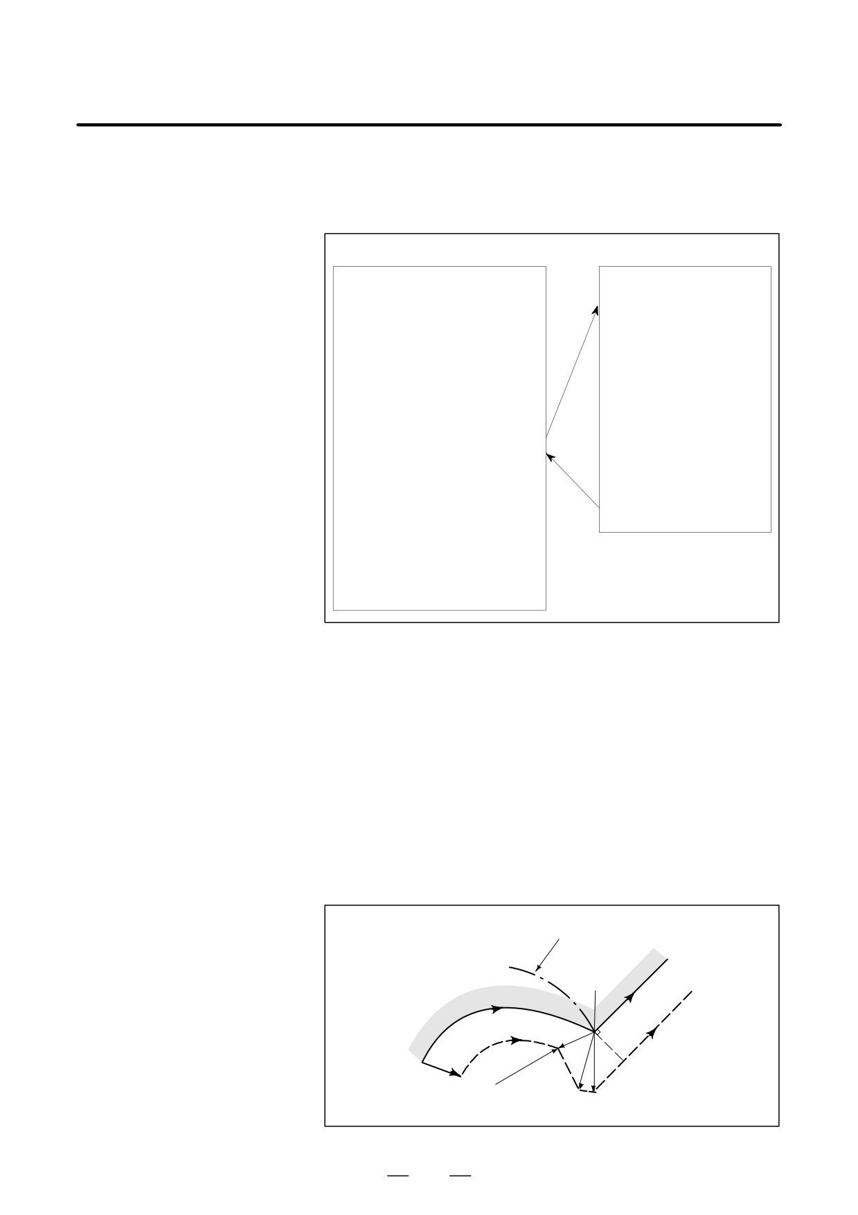
< Sample program >
Main program
Subprogram
O0002 ;
O0001 ;
G00X50.Y50. ;
G05P10000 ; HPCC-ON
G00X100.Y200. ;
M11 ;
G02I20.F3000 ;
G91G01X100Y200Z300F2000 ;
G01X100. ;
X200Y300Z400 ;
G03I80. ;
X300Y400Z500 ;
G01X-50. ;
X400Y500Z600 ;
G02I100.F5000 ;
X300Y400Z500 ;
M98P0002 ; SUB PROGRAM
L
X10. ;
G01X200.Y300.F1500 ;
G05P0 ; HPCC-OFF
X50.Y100.Z150. ;
G90G51X0Y0Z0 ;
T24 ;
X500Y400Z300 ;
M99 ;
X600Y500Z400 ;
G50 ;
G05 P10000 ; HPCC-ON
X100Y200 ;
X200Y400 ;
G05P0 ; HPCC-OFF
Note) When bit 1 of parameter MSU
G04X3. ;
No. 8403 is 1
M30 ;
When the cutter compensation C option is provided, cutter compensation
D Cutter compensation C
C is enabled even in HPCC mode. Operation in the offset mode is the
same as when HPCC mode is not set, except in the following cases:
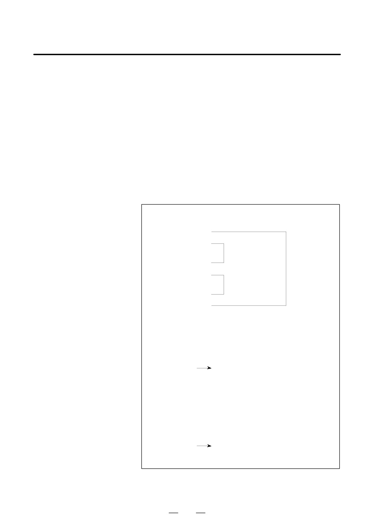
S When the end point for an arc does not lie on the arc
In the HPCC mode, when the end point for an arc does not lie on the
arc, the start point and end point are connected with a smooth curve;
no arc leading line is created. In this case, the system assumes an
imaginary circle to perform cutter compensation C. The center of the
imaginary circle is the same as the center of the arc, but the imaginary
circle passes through the end point. Under the assumption that cutter
compensation has been performed with respect to the imaginary circle,
the system creates a vector and performs compensation.
Imaginary circle
Arc end point
Programmed path
r
r
S
L
Center
L
L
502
B-63534EN/02
PROGRAMMING
19. HIGH SPEED CUTTING FUNCTIONS
S When the offset mode is canceled temporarily
In the HPCC mode, automatic reference position return (G28) and
automatic return from the reference position
(G29) cannot be
specified. Therefore, commands that must cancel the offset mode
temporarily cannot be specified.
When using cutter compensation C in the HPCC mode, note the following
points:
(1) When G05 P10000 and G05 P0, and G41/G42 and G40 are to be
specified together, G41/G42 to G40 must be nested between G05
P10000 and G05 P0. This means that HPCC mode cannot be started
or canceled in cutter compensation (G41/G42) mode. If such a
specification is made, the P/S alarm No.0178 or P/S alarm No.5013
P/S alarm is issued.
(Example of a correct program)
L
G05 P10000 ;
L
G41 X__ Y__ D01 ;
Cutter compensation
L
(G41) mode
G40 X__ Y__ ;
HPCC mode
L
G42 X__ Y__ D02 ;
Cutter compensation
L
(G42) mode
G40 X__ Y__ ;
L
G05 P0 ;
L
(Example of an incorrect program (1))
L
G41 X__ Y__ D01 ;
L
When the start of HPCC mode is specified
G05 P10000 ;
in cutter compensation mode, the P/S
alarm No.0178 is issued.
(Example of an incorrect program (2))
L
G05 P10000 ;
L
G41 X__ Y__ D01 ;
L
When cancellation of HPCC mode is specified
G05 P0 ;
in cutter compensation mode, the P/S alarm
No.5013 alarm is issued.
503
19. HIGH SPEED CUTTING FUNCTIONS
PROGRAMMING
B-63534EN/02
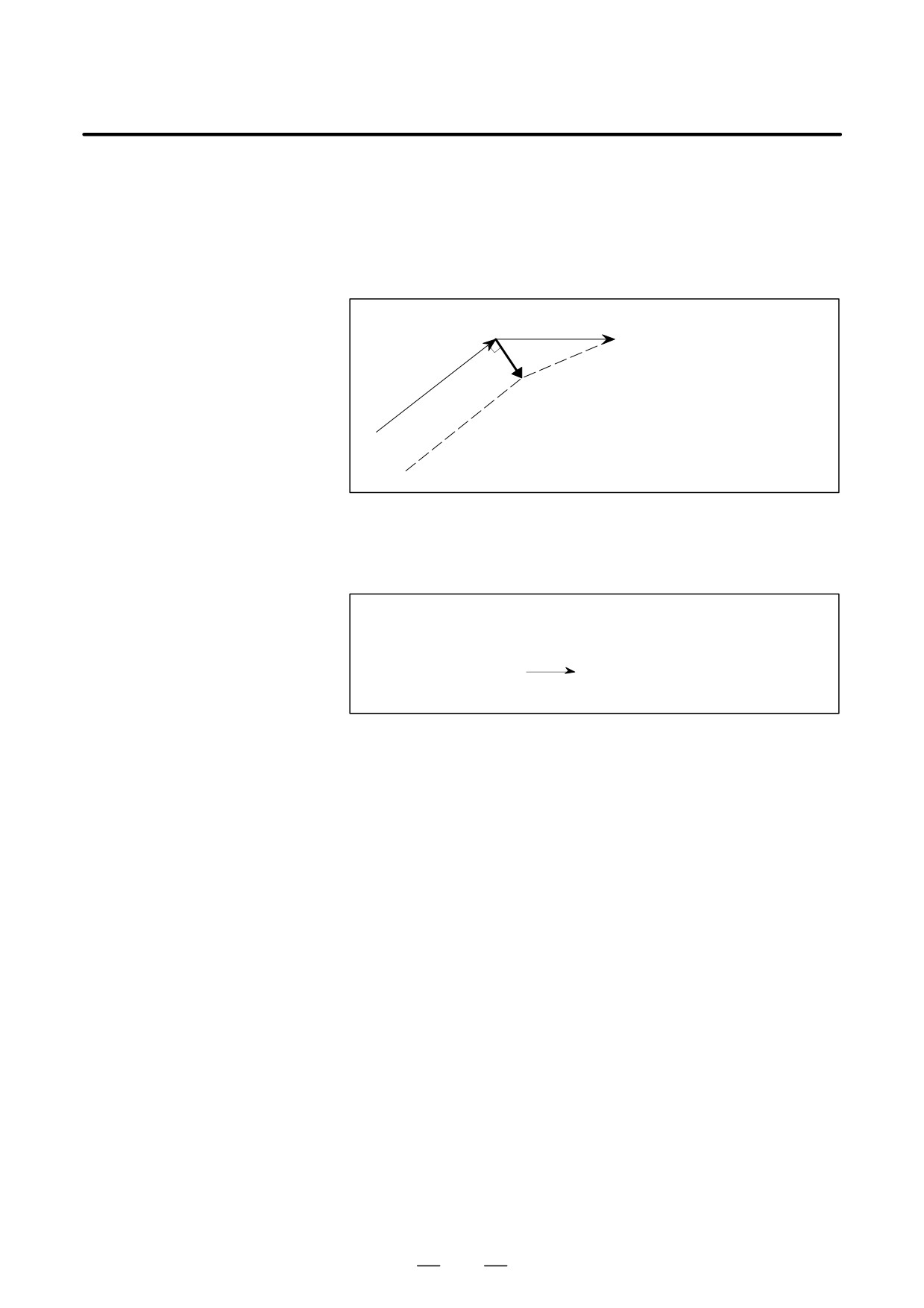
(2) When a block containing no movement operation is specified together
with the cutter compensation cancel code (G40), a vector with a length
equal to the offset value is created in a direction perpendicular to the
movement direction of the previous block. Cutter compensation mode
is canceled while this vector still remains. This vector is canceled
when the next move command is executed.
N7
N8
L
N6 G91 X100. Z100. ;
N6
N7 G40 ;
N8 X100. ;
L
If cutter compensation mode is canceled while a vector still remains
and HPCC mode is canceled before a move command is specified,
the P/S alarm No.5013 is issued.
L
N6 G91 X100. Z100. ;
N7 G40 ;
N8 G05 P0 ;
The P/S alarm No. 5013 is issued.
L
(3) When an offset value is changed during cutter compensation C in
HPCC mode, the new offset value is not used until a block specifying
a D code appears.
504
B-63534EN/02
PROGRAMMING
19. HIGH SPEED CUTTING FUNCTIONS
D Positioning and auxiliary
When bit 1 of parameter MSU No. 8403 is set to 1, G00, M, S, T, and B
functions
codes can be specified even in HPCC mode. When specifying these codes
in HPCC mode, note the following:
(1) When a G00, M, S, T, or B code is specified in cutter compensation
mode, the offset vector created in the previous block is maintained.
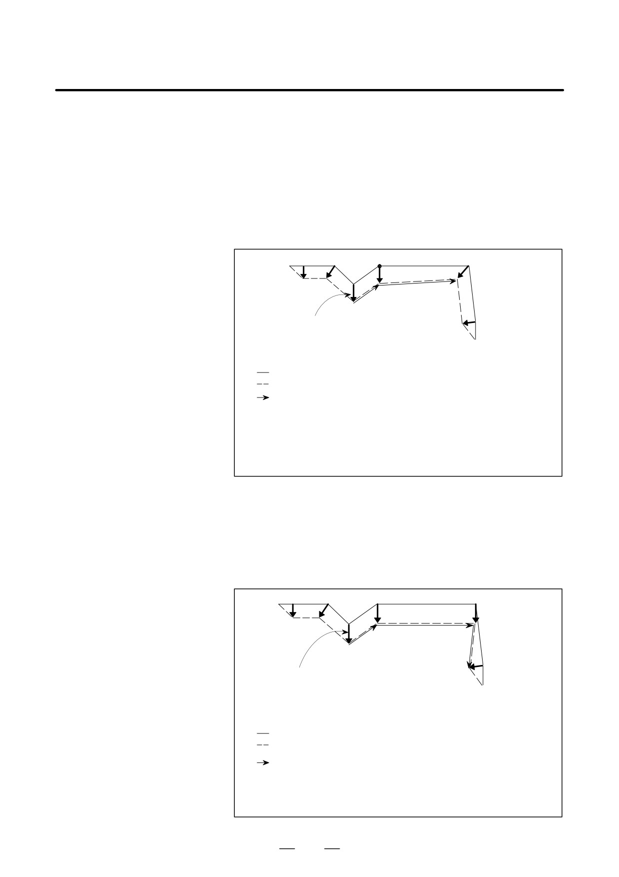
(Example 1) When the following program is executed for
machining with offset value D1 set to 10 mm, the start
point of N6 is determined by the vector created
between N3 and N4:
N1
N2
N5
N6
N3 N4
N7
This vector is used as the vector
N8
between N4 and N6.
O0001 ;
G92 G90 X-10. Y20. ;
G05 P10000 ;
Programmed path
N1 G01 G42 X0 D1 F1000 ;
Tool path
N2 X20. ;
An incorrect offset value is
N3 X40. Y0 ;
used in this range.
N4 X60. Y20 ;
N5 M01 ;
N6 X80. ;
N7 X90. Y-20. ;
N8 G40 Y-50. ;
G05 P0 ;
M30
(Example 2) When the following program is executed for
machining with offset value D1 set to 10 mm, the start
point of N5 is determined by the vector created
between N3 and N4. If the simplified G00 execution
function is enabled (by setting bit 7 of parameter SG0
No. 8403 to 1), a correct vector can be obtained at the
intersection of N4 and N5.
N1
N2
N5
N3 N4
N6
This vector is used as the vector between
N7
N4 and N5, and N5 and N6.
O0001 ;
G92 G90 X-10. Y20. ;
G05 P10000 ;
N1 G01 G42 X0 D1 F1000 ;
Programmed path
N2 X20. ;
Tool path
N3 X40. Y0 ;
N4 X60. Y20 ;
An incorrect offset value is
N5 G00 X80. ;
used in this range.
N6 G01 X90. Y-20. ;
N7 G40. Y-50. ;
G05 P0 ;
M30
505

19. HIGH SPEED CUTTING FUNCTIONS
PROGRAMMING
B-63534EN/02
(2) When G00 is specified with bit 7 of parameter SG0 No. 8403 set to 1,
the following points should be noted:
⋅Since the G00 command is replaced by the G01 command, the tool
moves at the feedrate set in parameter No. 8481 even when data is
specified for two axes.
Example) If the following is specified when parameter No. 8481 is
set to 1000 mm/min, F1000 is used instead of F1414
G00 X100. Y100. ;
D Since the G00 command is replaced by the G01 command, rapid
traverse override is disabled and cutting feed override is enabled.
D For acceleration/deceleration after interpolation, the time constant
used for cutting feed acceleration/deceleration after interpolation
is selected.
D Linear and bell-shaped acceleration/deceleration before inter-
polation in HPCC mode is enabled.
D No position check is performed.
D Linear interpolation type positioning is performed.
D Status display
When G05P10000 is specified, “HPCC” starts blinking at the right-
bottom of the screen. While “HPCC” is blinking, the system performs
automatic operation in HPCC mode.
Display example for when the system is in HPCC mode
(Program screen)
PROGRAM(MEMORY)
O1234 N00010
G05 P10000 ;
Executed block
N10 X10. Y10. Z10. ;
Block being executed
N20 X10. Y10. Z10. ;
/ N30 X10. Y10. Z10. ;
/2 N40 X10. Y10. Z10. ;
N50 X10. Y10. Z10. ;
N60 X10. Y10. Z10. ;
N70 (FANUC Series 16) ;
N80 X10. Y10. Z10. ;
N90 X10. Y10. Z10. ;
N100 X10. Y10. Z10. ;
N110 X10. Y10. Z10. ;
G05 P0 ;
MEM STRT MTN
***
01 : 23 : 45
HPCC
PRGRM
NEXT
(OPRT)
506

B-63534EN/02
PROGRAMMING
19. HIGH SPEED CUTTING FUNCTIONS
Limitations
D Modes that can be
Before G05P10000 can be specified, the following modal values must be
specified
set. If they are not set, the P/S alarm No. 5012 is issued.
G code
Meaning
G13.1
Cancels polar coordinate interpolation.
G15
Cancels a polar coordinate command.
G40
Cancels cutter compensation (M series).
G40.1
Cancels normal direction control (for the M series only).
G50
Cancels scaling.
G50.1
Cancels the programmable mirror image function.
G64
Cutting mode
G69
Cancels coordinate conversion.
G80
Cancels canned cycles.
G94
Feed per minute
G97
Cancels constant surface speed control.
M97
Cancels interrupt type macros.
D Single block
The G05P10000 block cannot be executed in the single block mode.
D Second feedrate override
The second feedrate override and optional block skip functions cannot be
and optional block skip
used in HPCC mode unless these options are provided.
D Invalid command
Externally-requested deceleration, feed at address F with one digit, and
automatic corner override commands are ignored.
D MDI operation
Switching to the MDI mode cannot be performed in HPCC mode. In
addition, MDI operation is not possible.
D Interlock
Interlock (for each axis and in each direction) is disabled in HPCC mode.
D Mirror image and
In HPCC mode, never change the external mirror image signal (DI
machine lock
signal), parameter-set mirror image, and each-axis machine lock.
D Calculator-type input
In HPCC mode, calculator type input (when bit 0 of parameter DPI No.
3401 is 1) is ignored.
D Program reset
A program containing G05P10000; cannot be restarted.
D Custom macro
No custom macros can be specified in HPCC mode.
D Scaling
In scaling for each axis, a negative magnification cannot be used to create
a mirror image.
507
19. HIGH SPEED CUTTING FUNCTIONS
PROGRAMMING
B-63534EN/02
19.9
LOOK-AHEAD
BELL-SHAPED
ACCELERATION/DEC
ELERATION BEFORE
INTERPOLATION
TIME CONSTANT
CHANGE FUNCTION
General
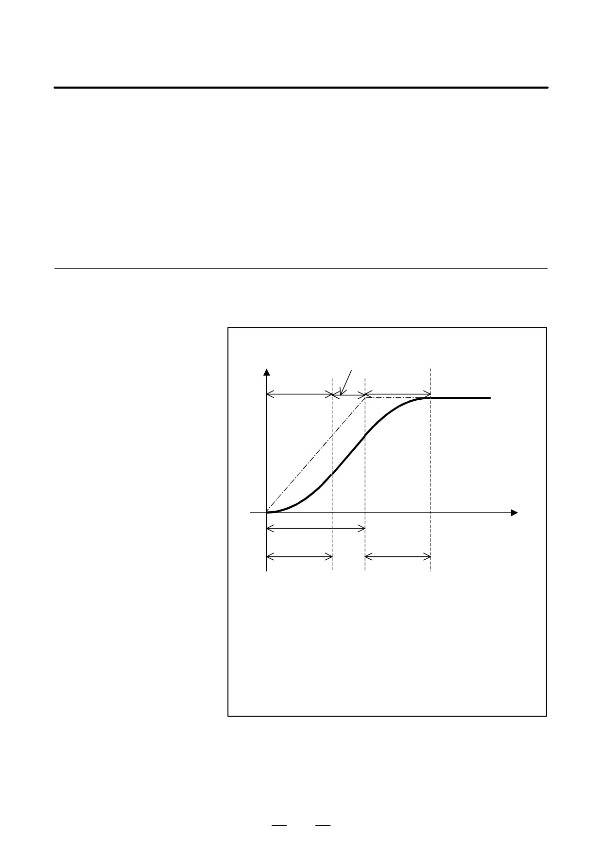
In Look-ahead bell-shaped acceleration/deceleration before
interpolation, the speed during acceleration/deceleration is as shown in
the figure below.
Linear
Speed
acceleration/deceleration
Non-linear
Non-linear
acceleration/deceleration
acceleration/deceleration
Specified
speed
Time
T1
T2
T2
T1: Time determined from the specified speed and the specified acceleration
Specified acceleration:
In case of AI contour control (AICC)
and AI nano contour control (AI nanoCC)
Parameter No.1770/Parameter No.1771
In case of AI High precision contour control (AI-HPCC)
and AI nano High precision contour control (AI-nanoHPCC)
Parameter No.8400/Parameter No.8401 (or No.19510)
T2: Acceleration change time
In case of AICC and AI nanoCC : Parameter No.1772
In case of AI-HPCC and AI-nanoHPCC : Parameter No.8416
Fig.19.9 (a)
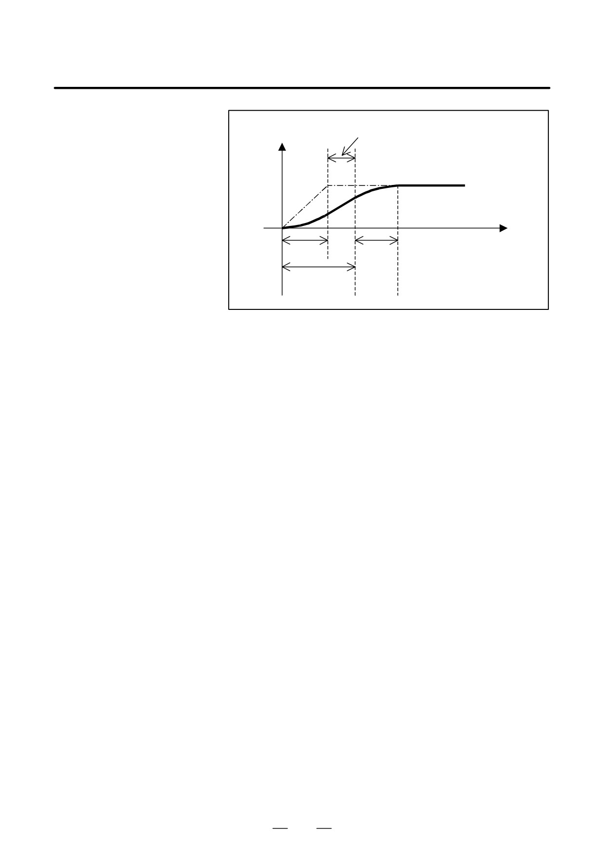
The time T1, shown above, varies with the specified speed. If the
specified speed is low, the speed will be as shown below, causing linear
acceleration/deceleration not reaching the specified acceleration.
508
B-63534EN/02
PROGRAMMING
19. HIGH SPEED CUTTING FUNCTIONS
Linear acceleration/deceleration not reaching specified acceleration/deceleration
Speed
Specified
speed
Time
T1
T1
T2
Fig.19.9 (b)
If linear acceleration/deceleration not reaching the specified acceleration
occurs in AI contour control (AICC) mode or AI Nano contour control
(AI nanoCC) mode or AI High Precision Contour control (AI-HPCC)
mode or AI Nano High Precision Contour control (AI-nanoHPCC) mode
as shown above, this function shortens the acceleration/deceleration time
by changing the internal acceleration for acceleration/deceleration before
interpolation and the bell-shaped time constant in order to generate an
acceleration/deceleration pattern as close as possible to that permits
optimum bell-shaped acceleration/deceleration before interpolation for
the specified speed.
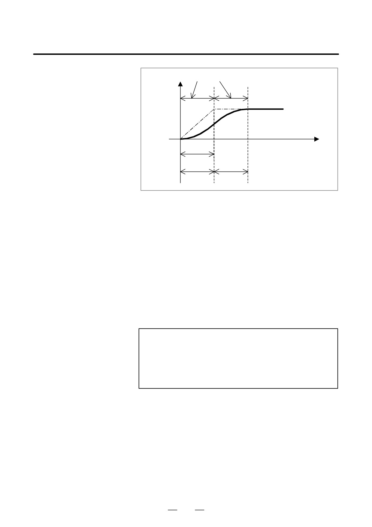
Optimum bell-shaped acceleration/deceleration before interpolation, as
mentioned here, refers to bell-shaped acceleration/deceleration before
interpolation in which
if T2 > T1, T1 and T2 are changed to T1’ and T2’ as shown in the figure
below so that linear acceleration/deceleration not reaching the specified
acceleration/deceleration does not occur.
This function becomes effective for the Acceleration /deceleration before
look-ahead interpolation in AI contour control mode or AI Nano contour
control mode or AI High Precision Contour control mode or AI Nano
Contour control mode..
509
19. HIGH SPEED CUTTING FUNCTIONS
PROGRAMMING
B-63534EN/02
Speed Non-linear acceleration/deceleration
Specified speed
Time
T1’
T2’
T2’
Fig.19.9 (c)
Description
D Methods of specifying the
The acceleration/deceleration reference speed is the feedrate used as the
acceleration/deceleration
reference for calculating optimum acceleration. In Fig.19.9 (c), it is
reference speed
equivalent to the specified speed used to determine T1’ and T2’.
There are three methods for specifying the acceleration/deceleration
reference speed.
(1) Specifying the speed using an F in a G05.1 Q1 (AICC or AI nanoCC)
block or G05 P10000 (AI-HPCC or AI-nanoHPCC) block
(2) Setting the speed on Parameter
(3) Setting the speed specified with the F command issued at the start of
cutting as the reference speed
NOTE
This function is effective if BCG (No. 7055 bit 3) is 1 in AI
contour control mode or AI Nano contour control mode , or
if BCG (No.19501#6) is 1 in AI High Precision Contour
control mode or AI Nano High Precision Contour control
mode.
510

B-63534EN/02
PROGRAMMING
19. HIGH SPEED CUTTING FUNCTIONS
(1) Specifying the speed
If an F command is used in a G05.1 Q1 (AICC or AI nanoCC) block or
in a G05.1 Q1 block or
G05 P10000 (AI-HPCC or AI-nanoHPCC) block, the speed specified
G05 P10000 block
with the F command is assumed the acceleration/deceleration reference
speed.
This acceleration/deceleration reference speed is cleared upon a reset.
After the acceleration/deceleration reference speed is cleared upon a reset
or after the power is turned off and then on again, the
acceleration/deceleration reference speed specified for parameter No.
7066 (AICC or AI nanoCC) or No.19520 (AI-HPCC or AI-nanoHPCC)
will be used.
(Method (2), described later)
If the acceleration/deceleration reference speed specified for the
parameter is 0, the feedrate assumed at the start of cutting will be assumed
the acceleration/deceleration reference speed.
(Method (3), described
later)
(Program example)
G05.1 Q1 F5000 ; ··· Sets the reference speed to 5000 mm/min.
The F command used in a G05.1 block is used to
specify the acceleration/deceleration reference speed,
and is also used as a normal F command.
Even if the feedrate is changed during the execution of the machining
program, the acceleration/deceleration reference speed specified with the
above command remains in effect. If this occurs, the machining time may
become longer because machining is performed at the feedrate different
from the acceleration/deceleration reference speed.
For this reason, the acceleration/deceleration reference speed to be
specified with the above command should be as close as possible to the
actual machining speed.
NOTE
The G05.1Q1Fxxxx, G05P10000Fxxxx command must be
issued in feed per minute (G94) mode.
If this command is issued in another mode, the speed
specified with this command will be generated the alarm
(PS5111).
(2) Setting the speed on
the acceleration/deceleration reference speed is set in parameter No. 7066
the Parameter
(AICC or AI nanoCC) or No.19520 (AI-HPCC or AI-nanoHPCC).
Because these parameters must be set in input unit, when the input unit
is changed, these parameters must be changed.
This method is used if the G05.1Q1 block or G05 P10000 block does not
have an F command.
511

19. HIGH SPEED CUTTING FUNCTIONS
PROGRAMMING
B-63534EN/02
(3) Using the speed
The speed specified with the F command issued when a cutting block
specified with the F
group
(such as G01 and G02) starts is assumed the
command issued at
acceleration/deceleration reference speed,
This method is used if the G05.1Q1 block or G05 P10000 block does not
the start of cutting as
have an F command and the parameter of the acceleration/deceleration
the reference speed
reference speed is set to 0.
(G00)
G01 X--- Y--- Z--- F*** ;
X--- Y--- Z---
Cutting block group
X--- Y--- Z---
X--- Y--- Z---
G00 ;
Even if an F command is issued before a cutting block group and the F
command is effective to the cutting block group modally, the speed
specified with the modal F effective at the start of cutting will be assumed
the acceleration/deceleration reference speed.
D Acceleration/deceleratio
Optimum bell-shaped acceleration/deceleration before interpolation, as
n parameter calculation
mentioned here, refers to bell-shaped acceleration/deceleration before
method
interpolation in which linear acceleration/deceleration not reaching the
specified acceleration/deceleration does not occur if T2 > T1. Calculation
is performed as described below.
(1) If the bell-shaped acceleration/deceleration before interpolation time
constant T2’ is calculated under the condition that the bell-shaped
acceleration/deceleration before interpolation must not have a linear
portion,
T2*F
T2
'
=
A
T2: Acceleration change time specified for bell-shaped acceleration/
deceleration before interpolation
F: Acceleration/deceleration reference speed
A: Acceleration for the acceleration/deceleration before interpolation
512
B-63534EN/02
PROGRAMMING
19. HIGH SPEED CUTTING FUNCTIONS
(2) A proper acceleration is determined under the condition that the
acceleration change must be about the same as the setting so that
parameter changes do not cause considerable shock to the machine,
that is:
Acceleration after change
Acceleration before change
=
Acceleration change time
Acceleration change time
after change
before change
The acceleration change time is regarded to be the sum of the
acceleration change time of bell-shaped acceleration/deceleration
and the time constant of acceleration/deceleration after interpolation,
and the acceleration A’ for the acceleration/deceleration before
interpolation is determined as follows:
A
= 2'+Tc
A
'
T2+ Tc
A: Acceleration for the acceleration/deceleration before interpolation
Tc:Time constant of acceleration/deceleration after interpolation
Acceleration/deceleration is performed using T2’ and A’, determined
as described above.
513
19. HIGH SPEED CUTTING FUNCTIONS
PROGRAMMING
B-63534EN/02
19.10
OPTIMUM TORQUE
ACCELERATION/DEC
ELERATION
General
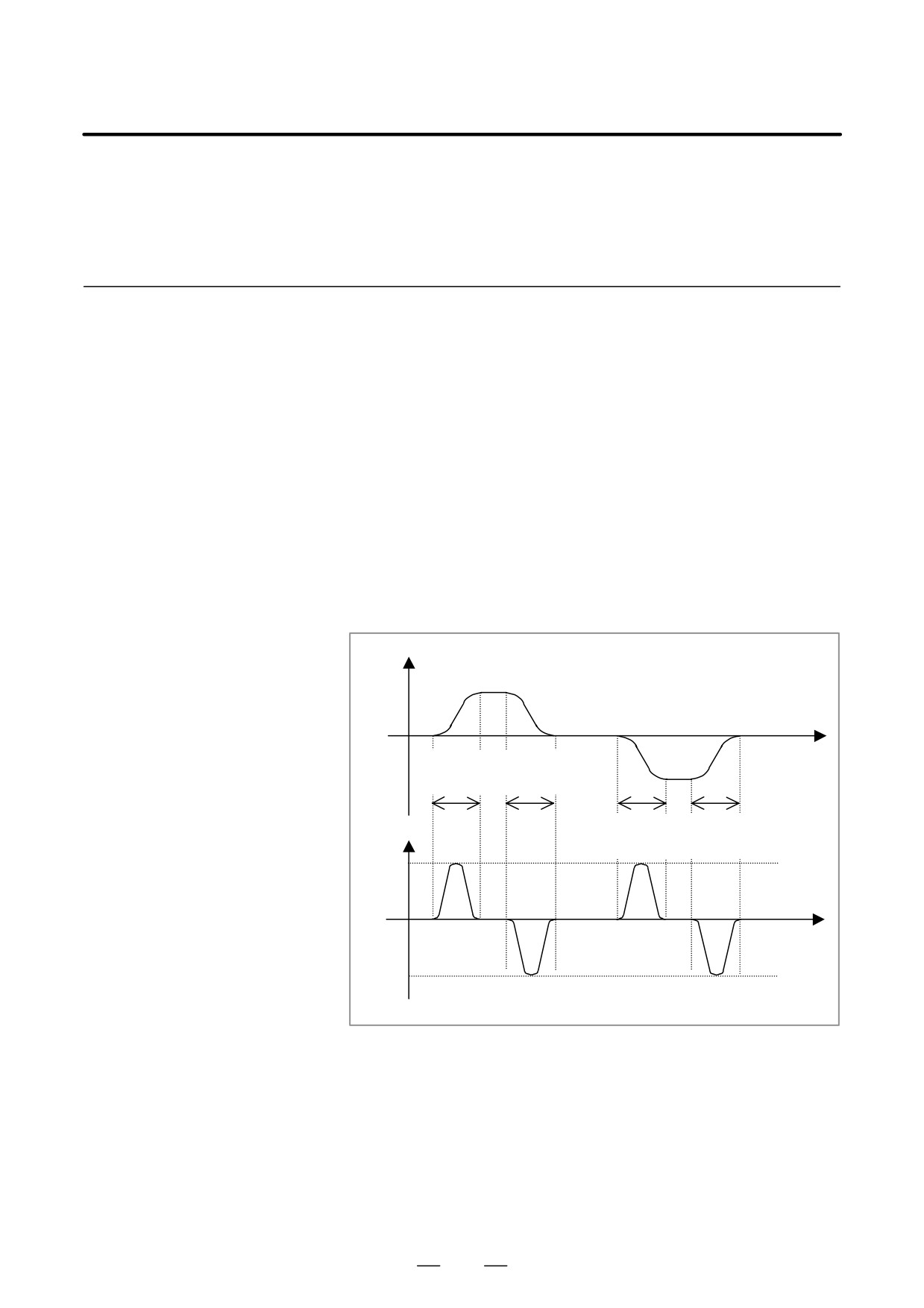
This function enables acceleration/deceleration in accordance with the
torque characteristics of the motor and the characteristics of the machines
due to its friction and gravity and performs linear type positioning with
optimum acceleration/deceleration during AI high precision contour
control mode or AI nano high precision contour control mode.
Usually, because of the friction of the machine, gravity, the torque
characteristics of the motor, and other factors, the acceleration/deceleration
performance (torque for acceleration/deceleration) is different with direction
of movement, acceleration or deceleration. In this function, acceleration
pattern of rapid traverse for the following situations, plus movement and
acceleration, plus movement and deceleration, minus movement and
acceleration, minus movement and deceleration can be set into parameters
according to the torque for acceleration/deceleration of each situation.
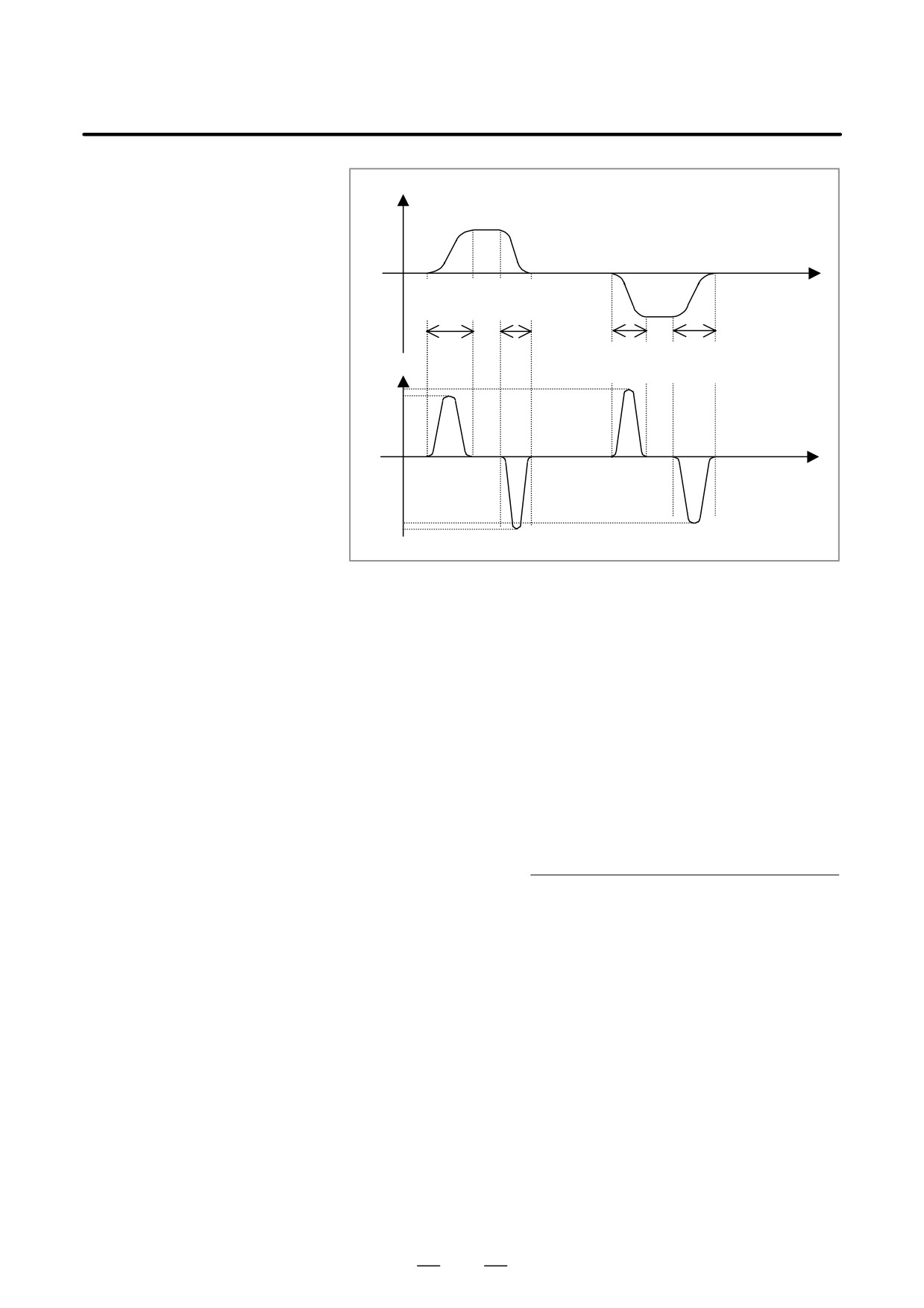
Acceleration/deceleration can be performed according to these parameter
setting, so that the most of the capability of the motor can be used and
positioning time can be reduced.
Speed
Acceleration
Deceleration
Time
and
and
+ move
+ move
Acceleration Deceleration
Acceleration
and
and
- move
- move
Time
Acc/Dec pattern is the same way in each condition.
Fig.19.10 (a) Conventional acceleration/declaration
514
B-63534EN/02
PROGRAMMING
19. HIGH SPEED CUTTING FUNCTIONS
Speed
Acceleration
Deceleration
and
and
Time
+ move
+ move
Acceleration
Deceleration
and
and
Acceleration
- move
- move
Time
Acc/Dec pattern can be changed in each condition.
Fig.19.10 (b) Acceleration/deceleration with this function
Description
Optimum torque acceleration/deceleration selects the acceleration pattern set
with parameters on the basis of the axial movement direction and the
acceleration/deceleration state, determines the acceleration for each axis
from the current speed, and controls the tangential acceleration/deceleration
for rapid traverse in AI high precision contour control and AI nano high
precision contour control mode.
D Calculation of the
The reference acceleration is the standard acceleration to set the
reference acceleration
acceleration pattern, usually this is the same as the acceleration for rapid
traverse at the selecting a motor.
No.1420
1000 (Rapid traverse rate)
Referenceacceleration[mm/sec2]
=
No.1773
60(Acc/Dec Time Constant of rapid traverse)
D Setting optimum torque
By setting both FAP, bit 0 of parameter No. 19540, and FRP, bit 5 of
acceleration/deceleration
parameter No. 19501, to 1 and setting parameter to determine the reference
acceleration (No. 1420 and No.1773 ) as below, the acceleration/deceleration
for rapid traverse in AI high precision contour control and AI nano high
precision contour control mode will be optimum torque acceleration/
deceleration. When Optimum torque acceleration/deceleration is enabled,
linear type positioning for rapid traverse is selected automatically in AI high
precision contour control and AI nano high precision contour control mode
even if the parameter LRP, bit 1 of parameter No. 1401, is set to 0 (nonlinear
type is selected). If rapid traverse is subject to optimum torque acceleration/
deceleration, after-interpolation acceleration/deceleration does not apply to
rapid traverse.
515
19. HIGH SPEED CUTTING FUNCTIONS
PROGRAMMING
B-63534EN/02
Table. 19.10 (a) Optimum torque acceleration/deceleration
FAP
FRP
Reference
Bell-shaped
Acceleration
19540#0
19501#5
accelera-
acceleration
pattern
tion
change time
1
1
No.1420
No.1774
See “Setting ac-
Before-
&
celeration pat-
interpolation
No.1773
tern data”
acc/dec for
rapid
traverse
To enable bell-shaped acceleration/deceleration in addition to optimum
torque acceleration/declaration, set HRB, bit 0 of parameter No. 19504
to
1and the bell-shaped acceleration change time with parameter
No.1774.
D Cases in which optimum
In case that optimum torque acceleration/deceleration is disabled,
torque acceleration/
acceleration/deceleration for rapid traverse will be after-interpolation
deceleration is disabled
acceleration/deceleration or before interpolation acceleration/deceleration.
When the command having the following restriction is commanded,
optimum torque acceleration/deceleration is disabled.
(Restriction)
Optimum torque acceleration/deceleration is disabled at the command
with the restriction ”AI high precision contour control mode or the AI
nano high precision contour control mode is automatically canceled once
and the buffering is inhibited” which is mentioned in the specification
manual for AI high precision contour control mode or the AI NANO high
precision contour control.
For example, during the following commands which includes the
M,S,T,B code, optimum torque acceleration/deceleration is disabled;
1. G00
100.M13; (G00 with M code)
2. G00
100.S1000; (G00 with S code)
3. G00
100.T01; (G00 with T code)
4. G00
100.B20; (G00 with B code)
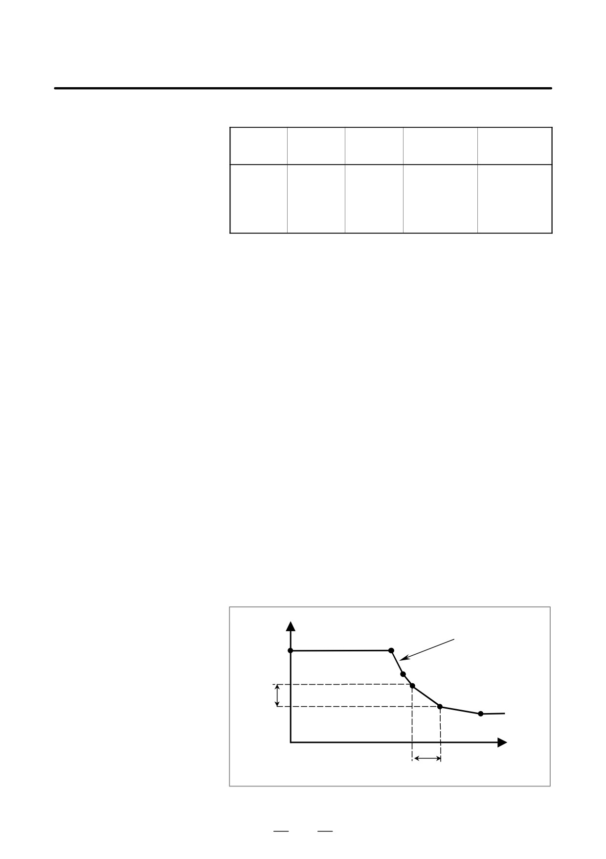
D Setting acceleration
pattern data
acceleration
P0
Acceleration pattern
P1
P2
Aa
P3
P4
Ab
P5
Speed
Fa
Fb
Fig.19.10 (c) Setting acceleration pattern
516

B-63534EN/02
PROGRAMMING
19. HIGH SPEED CUTTING FUNCTIONS
Set the speed and the acceleration at each of the acceleration setting points
P0 to P5 for each condition, plus movement and acceleration, plus
movement and deceleration, minus movement and acceleration, minus
movement and deceleration, and for each axis.
The line joining the acceleration setting points is regarded a acceleration
pattern.
For example, while the speed is between Fa and Fb in the previous figure,
the acceleration is calculated with Aa and Ab. Tangential acceleration is
controlled not to exceed the calculated acceleration for each axis.
Table. 19.10 (b) Parameters for acceleration pattern
Acceler
Speed
Acceleration parameter
ation
parameter
During acceleration
During deceleration
setting
During
During
During
During
point
movement
movement
movement
movement
in plus
in minus
in plus
in minus
direction
direction
direction
direction
P0
(Speed 0)
No.19545
No.19551
No.19557
No.19563
P1
No.19541
No.19546
No.19552
No.19558
No.19564
P2
No.19542
No.19547
No.19553
No.19559
No.19565
P3
No.19543
No.19548
No.19554
No.19560
No.19566
P4
No.19544
No.19549
No.19555
No.19561
No.19567
P5
No.1420
No.19550
No.19556
No.19562
No.19568
The speed at P0 is 0, and the speed at P5 is the rapid traverse rate specified
with parameter (No. 1420). The speeds at P1 to P4 are to be set into speed
parameters Nos. 19541 to 19544 as ratio to the rapid traverse speed
(parameter No. 1420).
Any acceleration setting point for which the speed parameter (one of Nos.
19541 to 19544) is set to 0 will be skipped, and the next point whose speed
parameter is set to a non-zero value will be joined together as acceleration
pattern.
The accelerations at P0 to P5 are to be set into acceleration parameters
Nos. 19545 to 19568 as ratio to the reference acceleration. If any of the
acceleration parameters Nos. 19545 to 19568 is set to 0, the acceleration
is assumed 100% (Reference acceleration). Acceleration parameters
should be set to 0 at the acceleration setting point whose speed parameter
is set to 0.
If this function is enabled and both parameter No.1773 and No. 1620 for
an axis are set to 0, the following values are assumed as the reference
acceleration for that axis:
1000.0 mm/sec/sec, 100.0 inch/sec/sec, 100.0 degrees/sec/sec
517
19. HIGH SPEED CUTTING FUNCTIONS
PROGRAMMING
B-63534EN/02
D Example of setting
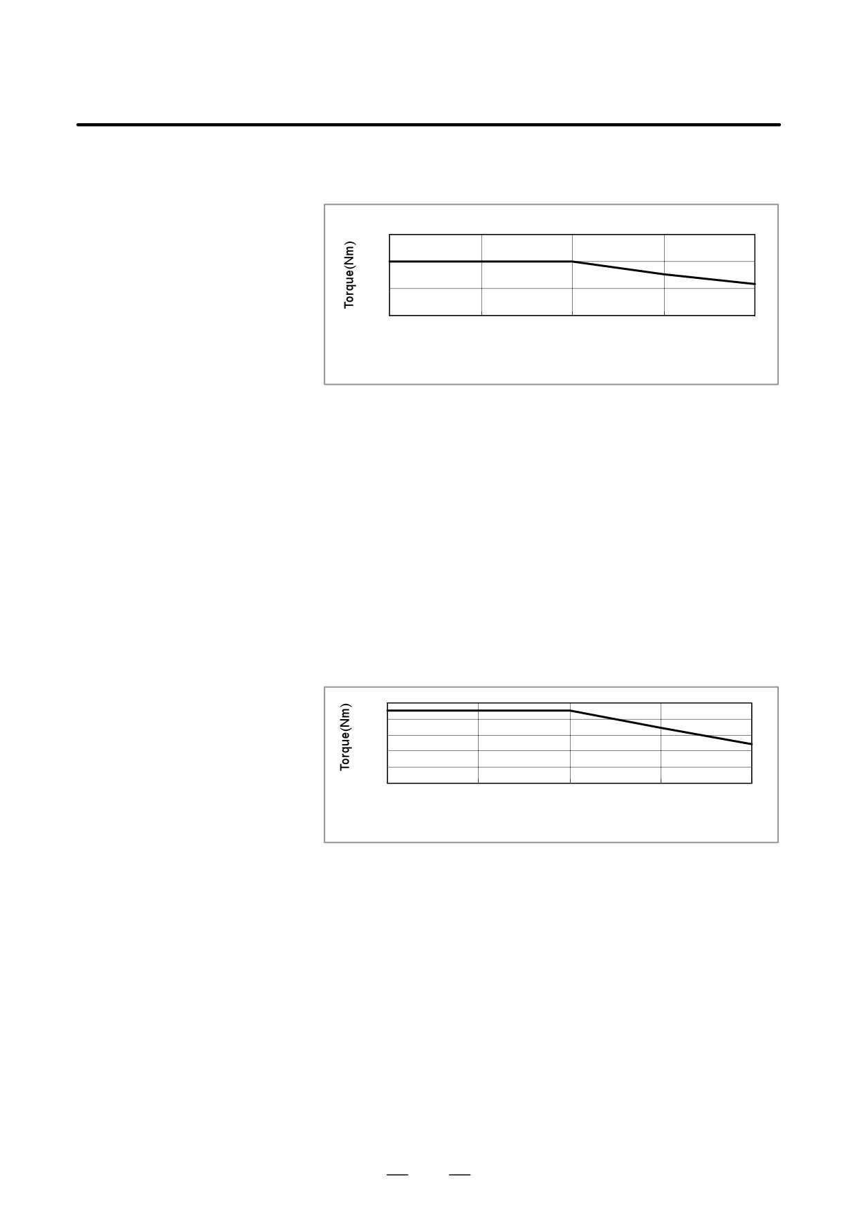
In this example, the machine is equipped with the aM30/4000i?.
acceleration pattern data
Motor speed at rapid traverse is 3000 (min-1).
150
100
50
0
0
1000
2000
3000
4000
Speed(min-1)
Fig.19.10 (d) Speed-torque characteristics of model a30/4000i
Specifications of the motor model a30/4000i
Rotor inertia
: 0.0099 (Kgm2)
Maximum torque
: 100 (Nm)
Speed : 0 to 2000 (min-1)
Torque at rapid traverse
: 79 (Nm)
Speed : 3000 (min-1)
Minimum torque
: 58 (Nm)
Speed : 4000 (min-1)
It assumes that 10 (Nm) is needed for the friction torque, so that the torque
for acceleration/deceleration is shown as the following figure.
Because the friction torque is different on each machine, it is necessary
to observe the actual torque output on the machine.
Maximum torque
:90(=100-10) (Nm) Speed: 0 to 2000 (min-1)
Torque at rapid traverse
:69(=79-10) (Nm) Speed: 3000 (min-1)
Minimum torque
:48(=58-10) (Nm) Speed: 4000 (min-1)
100
80
60
40
20
0
0
1000
2000
3000
4000
Speed(min-1)
Fig.19.10 (e) Torque for Acc/Dec with consideration of friction
518

B-63534EN/02
PROGRAMMING
19. HIGH SPEED CUTTING FUNCTIONS
Let the torque be x (Nm), the inertia be y(Kgm2), and the ball screw pitch
p(mm), then the acceleration A is calculated as follows:
x[N @ m]
p
x([kg @ mńsec2][m])
p
A+
[mm] +
[mm]
y[kg @ m2]
2p
y[kg @ m2]
2p
x p
ĂĂ+
2p y[mmńsec2]
Machine specification is assumed as follows,
Ball screw pitch
: 16 (mm)
Inertia
: The machine inertia is to be 2.0 times higher than that
of the rotor.
(Rotor inertia: 0.0099 (Kgm2))
The acceleration at maximum torque is,
90
16
2p
3.0
0.0099+7717[mmńsec2]
The acceleration at rapid traverse is,
69
16
2p
3.0
0.0099+5916[mmńsec2]
From the above data, the parameters related to acceleration pattern is
given in the table below.
The example assumes that the acceleration is the same regardless of
whether acceleration or deceleration is in progress or whether the
movement is in the plus or minus direction.
Table. 19.10 (c) Example of setting parameters related to
acceleration pattern (1/2)
Parameter
Setting
Unit
Remarks
No.
Rapid
1420
48000.
mm/
The ball screw pitch is as-
traverse
min
sumed 16 mm, so that the rapid
rate
traverse rate is 48000 mm/min
at the maximum speed 3000
(min-1).
Refer-
1773
194
msec
Reference acceleration is
ence ac-
48000/60
= 4124 (mm/sec2)
celeration
194/1000
Speed at
19541
6666
0.01%
66.66% is set at P1 because
P1
the torque 90(Nm) is constant
up to 2000 (min-1) (32000mm/
min).
0.6666=32000/48000
Speeds
19542 to
0
0.01%
P2 to P4 are skipped because
at P2 to
19544
the torque drops almost linearly
P4
from the speed 2000 (min-1) to
3000 (min-1).
Accelera-
19545,19551
18712
0.01%
At P0, 90(Nm) can be used for
tion at P0
19557,19563
the acceleration/deceleration,
so set the ratio 7717 (mm/sec2)
to 4124 (mm/sec2).
1.8712 = 7717/4124
519