FANUC Series 16i/160i/160is-MB, Series 18i/180i/180is-MB5, Series 18i/180i/180is-MB. Operator's Manual - page 20
20. AXIS CONTROL FUNCTIONS
PROGRAMMING
B-63534EN/02
S In C-axis servo delay compensation (G83), compensation is not
applied to the integer part of the gear pitch. The compensation
direction is opposite to that of the C-axis rotation.
D C-axis synchronous
S C-axis handle interrupt
shift
During synchronization between the hob axis and C-axis, manual
handle interrupt can be performed for the C-axis. The C-axis is
shifted by the amount of the handle interrupt.
For details of handle interrupts, refer to the relevant manual supplied
by the machine tool builder.
S Synchronous shift by programming
During synchronization between the hob axis and C-axis, the C-axis
can be interrupted using G01. In this case, be careful not to exceed the
maximum cutting speed.
Example: Hob shifting during synchronization
G01 Y__ C__ F__ ;
D Manual setting of
When the rotation of the position coder is stopped, the position of the
one-rotation signal
one-rotation signal is shifted in the CNC as if the one-rotation signal had
been output with the position coder at the current position.
For details, refer to the relevant manual supplied by the machine tool
builder.
D Retract function
In both automatic and manual operation mode, retract movement can be
made over the distance specified by parameter No. 7741, along the axis
set by bit 0 (RTRx) of parameter No. 7730.
For details, refer to the relevant manual supplied by the machine tool
builder.
Limitations
D Setting a rotation axis
Set a rotation axis as the C-axis (workpiece axis).
(Bit 0 (RoTx) of
parameter No. 1006 = 1)
D Gear ratio of the spindle
Set parameter No.7700#5 to 0 and also set the gear ratio of the spindle
(bob axis) and Position
(bob axis) to the position coder in parameter No.7711.
coder
550

B-63534EN/02
PROGRAMMING
20. AXIS CONTROL FUNCTIONS
20.8
In the same way as with the hobbing machine function, to machine
(grind/cut) a gear, the rotation of the workpiece axis connected to a servo
SIMPLE ELECTRIC
motor is synchronized with the rotation of the tool axis (grinding
GEAR BOX
wheel/hob) connected to the spindle motor. To synchronize the tool axis
(G80, G81)
with the workpiece axis, an electric gear box (EGB) function is used for
direct control using a digital servo system. With the EGB function, the
workpiece axis can trace tool axis speed variations without causing an
error, thus machining gears with great precision.
Some conditions must be satisfied for setting the workpiece axis and tool
axis. For details, refer to the relevant manual provided by the machine
tool builder.
20.8.1
Simple Electric Gear
Box (G80, G81)
Format
G81 T _ L _ Q _ P _ ; Starts synchronization.
S_ M03 (or M04) ;
Starts tool axis rotation.
M05 ;
Stops tool axis rotation.
G80 ;
Cancels synchronization.
T : Number of teeth (Specifiable range: 1 to 1000)
L : Number of hob threads
(Specifiable range: -21 to +21 with 0 excluded)
Q: Module or diametral pitch
Specify a module in the case of metric input.
(Unit:
0.00001 mm, Specifiable range: 0.01 to 25.0 mm)
Specify a diametral pitch in the case of inch input.
(Unit:
0.00001 inch-1, Specifiable range: 0.01 to 25.0 inch-1)
P : Gear helix angle
(Unit:
0.0001 deg, Specifiable range: -90.0 to 90.0 deg.)
* When specifying Q and P, the user can use a decimal point.
551
20. AXIS CONTROL FUNCTIONS
PROGRAMMING
B-63534EN/02
Explanations
D Synchronization control
1
Start of synchronization
When synchronization mode is set with G81, the synchronization
switch of the EGB function is closed, and synchronization between the
tool axis and workpiece axis starts. At this time, synchronization
mode signal SYNMOD is turned on. During synchronization, the
rotation of the tool axis and workpiece axis is controlled so that the
relationship between T (number of teeth) and L (number of hob
threads) can be maintained. Moreover, the synchronous relationship
is maintained regardless of whether the operation is automatic or
manual during synchronization.
G81 cannot be specified again during synchronization. Moreover, the
specification of T, L, Q, and P cannot be modified during
synchronization.
2
Start of tool axis rotation
When the rotation of the tool axis starts, the rotation of the workpiece
starts so that the synchronous relationship specified in the G81 block
can be maintained.
The rotation direction of the workpiece axis depends on the rotation
direction of the tool axis. That is, when the rotation direction of the
tool axis is positive, the rotation direction of the workpiece axis is also
positive; when the rotation direction of the tool axis is negative, the
rotation direction of the workpiece axis is also negative. However, by
specifying a negative value for L, the rotation direction of the
workpiece axis can be made opposite to the rotation direction of the
tool axis.
During synchronization, the machine coordinates of the workpiece
axis and EGB axis are updated as synchronous motion proceeds. On
the other hand, a synchronous move command has no effect on the
absolute and relative coordinates.
3
Termination of tool axis rotation
In synchronism with gradual stop of the tool axis, the workpiece axis
is decelerated and stopped. By specifying the command below after
the spindle stops, synchronization is canceled, and the EGB
synchronization switch is opened. At this time, the synchronization
mode signal (SYNMOD) is turned off.
4
Cancellation of synchronization
The position of the workpiece axis after travel during synchronization
is reflected in the absolute coordinates when synchronization is
canceled; from this point, absolute command programming is enabled
for the workpiece axis. By setting bit 0 (HOBRST) of parameter No.
7700 to 0, synchronization can also be canceled upon reset.
* The synchronization mode is canceled by a servo alarm, PS000
alarm, or emergency stop.
552
B-63534EN/02
PROGRAMMING
20. AXIS CONTROL FUNCTIONS
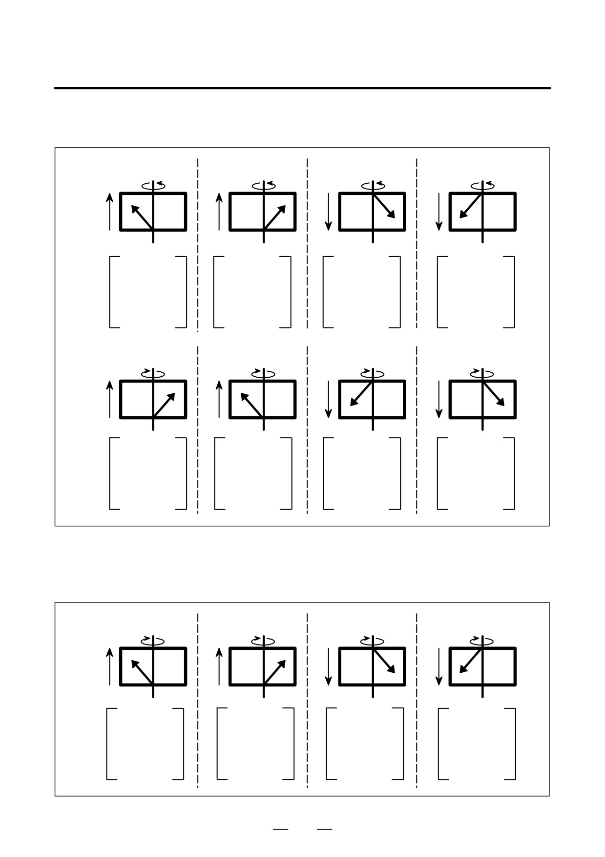
D Helical gear
When a helical gear is to be produced, the compensation of workpiece axis
compensation
rotation is needed according to the travel distance on the Z-axis (axial
feed).
Helical gear compensation is performed by adding compensation pulses
calculated from the formula below to the workpiece axis:
Z sin (P)
Compensation angle =
360 (For metric input)
p T Q
or
Z Q sin (P)
Compensation angle =
360 (For inch input)
p T
where
Compensation angle: Signed absolute value (deg)
Z: Amount of travel on the Z-axis after the specification of G81
(mm or inch)
P : Signed gear helix angle (deg)
T: Number of teeth
Q: Module (mm) or diametral pitch (inch-1)
The values of P, T, and Q are to be programmed.
553
20. AXIS CONTROL FUNCTIONS
PROGRAMMING
B-63534EN/02
D Direction of helical gear
1
When bit 2 (HDR) of parameter No. 7700 = 1
compensation
(a)
(b)
(c)
(d)
+Z
+C
+Z
+C
+Z
+C
+Z
+C
– Z
- Z
- Z
- Z
C :
+
C :
+
C :
+
C :
+
Z :
+
Z :
+
Z :
-
Z :
-
P :
+
P :
-
P :
+
P :
-
Compensation
Compensation
Compensation
Compensation
direction
:
+
direction
:
-
direction
:
-
direction
:
+
(e)
(f)
(g)
(h)
+Z
-C
+Z
-C
+Z
-C
+Z
-C
– Z
- Z
- Z
- Z
C :
-
C :
-
C :
-
C :
-
Z :
+
Z :
+
Z :
-
Z :
-
P :
+
P :
-
P :
+
P :
-
Compensation
Compensation
Compensation
Compensation
direction
:
-
direction
:
+
direction
:
+
direction
:
-
2
When bit 2 (HDR) of parameter No. 7700 = 0 (Items (a) to (d) are
the same as for 1.)
(e)
(f)
(g)
(h)
+Z
-C
+Z
-C
+Z
-C
+Z
-C
– Z
- Z
- Z
- Z
C :
-
C :
-
C :
-
C :
-
Z :
+
Z :
+
Z :
-
Z :
-
P :
+
P :
-
P :
+
P :
-
Compensation
Compensation
Compensation
Compensation
direction
:
+
direction
:
-
direction
:
-
direction
:
+
554
B-63534EN/02
PROGRAMMING
20. AXIS CONTROL FUNCTIONS
D Coordinates in helical
In helical compensation, the machine coordinates and absolute
compensation
coordinates of the workpiece axis (4th axis) are updated by the amount of
helical compensation.
D Retraction
By turning on the retract signal RTRCT (on a rising edge) in automatic
operation mode or manual operation mode, a retract movement can be
made over the distance specified in parameter No. 7741 on the axis set in
bit
0 (RTRx) of parameter No. 7730. Upon completion of retract
operation, the retract completion signal RTRCTF is output.
D Feedrate at retraction
For retract operation, the feedrate specified in parameter No. 7740 is used.
During retract operation, the feedrate override capability is disabled.
D Retraction during
When the retract signal is turned on in automatic operation, retract
automatic operation
operation is performed, and automatic operation is stopped at the same
time.
D Synchronization
A synchronization coefficient is internally represented using a fraction
coefficient
(K2/K1) to eliminate an error. The formula below is used for calculation.
(a, b : Number of detector pulses per rotation of the tool axis, and number
of detector pulses per rotation of the workpiece axis (parameter Nos. 7772
and 7773), respectively)
K2
L
b
Synchronization coefficient =
=
K1
T
a
In the formula above, K2/K1 is obtained by reducing the right side to
lowest terms, but K1 and K2 must satisfy the following restriction:
-2147483648
x K2
x -2147483647
1
x K1
x 65535
When this restriction is not satisfied, the PS181 alarm is issued when G81
is specified.
D Manual handle interrupt
During synchronization, a manual handle interrupt can be used for the
workpiece axis and other servo axes.
D Move command during
During synchronization, a move command can be programmed for the
synchronization
workpiece axis and other servo axes. Note, however, that incremental
command programming for cutting feed must be used to specify a
workpiece axis move command.
Limitations
D Feed hold during
For retract movement, the feed hold capability is disabled.
retraction
D Retraction when alarm is
This function does not include a retract function used when an alarm is
issued
issued.
D Rapid traverse during
In synchronization mode, a cutting feedrate can be specified for the
synchronization
workpiece axis (4th axis). Rapid traverse cannot be specified using G00.
D Maximum speed
The maximum speeds of the tool axis and workpiece axis depend on the
detectors used.
D G code command during
During synchronization, G00, G28, G27, G29, G30, G53, G20, and G21
synchronization
cannot be specified.
D Drilling canned cycle
When this function is used, the drilling canned cycle cannot be used.
555
20. AXIS CONTROL FUNCTIONS
PROGRAMMING
B-63534EN/02
Examples
O1000 ;
N0010 M19 ;
Performs tool axis orientation.
N0020 G28 G91 C0 ;
Performs reference position return
operation of the workpiece axis.
N0030 G81 T20 L1 ;
Starts synchronization between the tool
axis and workpiece axis.
(The workpiece axis rotates 18° when
the tool axis makes one rotation.)
N0040 S300 M03 ;
Rotates the tool axis at 300 min-1.
N0050 G01 X
F
; Makes a movement on the X-axis
(for cutting).
N0060 G01 Z
F
; Makes a movement on the Z-axis
(for machining).
- - - - - - - - - - - - - - - - ;
- - - - - - - - - - - - - - - - ;
N0100 G01 X
F
; Makes a movement on the X-axis
(for retraction).
N0110 M05 ;
Stops the tool axis.
N0120 G80 ;
Cancels synchronization between the
tool axis and workpiece axis.
N0130 M30 ;
20.8.2
This function provides the capability that skip function or high speed skip
function can be commanded for work axis in the EGB(Electronic Gear
Skip Function for EGB
Box) synchronization mode.
Axis (G31.8)
The features are as follows.
- The program block to enable the function is not interrupted until the
total number of skip signal inputs reaches a value specified in the same
block.
- The synchronization by EGB is not stopped by any of skip signal
inputs.
- The machine coordinate position of the EGB axis (work axis) at each
time of the signal inputs is stored in one of consecutive custom macro
variables. The top number of the variables is specified in the block.
- The total number of the inputs is stored in another specified variable.
As for the EGB function, see the chapter “1.14 Simple Electric Gear Box”
of the Connection Manual (Functions) B-63523EN-1.
556
B-63534EN/02
PROGRAMMING
20. AXIS CONTROL FUNCTIONS
Format
G81 T_ L_ ;
(EGB mode on)
G31.8 G91 a0 P_ Q_ R_ ;
(EGB skip command)
a : EGB axis (Work axis)
P : The top number of the consecutive custom macro variables in
which the machine coordinate positions of the EGB axis (work
axis) at the skip signal inputs are stored.
Q: The maximum allowable number of the skip signal inputs.
(Range of command value: 1 - 200)
R : The number of the custom macro variable in which the total
number of the inputs is stored.
This data is usually the same as the value specified by Q.
Therefore this is not necessarily specified. Specify it when the
total number should be confirmed.
Explanations
G31.8 is a one-shot G code.
During the execution of the G31.8 block, the machine coordinate
positions of the EGB axis (work axis) at the skip signal inputs are stored
in the consecutive custom macro variables where the top number of the
variables is specified by P and the maximum allowable number of the skip
signal inputs is specified by Q.
The total number of the skip signal inputs (i.e. the same value specified
by Q) is stored in the variable specified by R.
Examples
G81 T200 L2 ;
(EGB mode on)
X_ ;
Z_ ;
G31.8 G91 C0 P500 Q200 R1 ; (EGB skip command)
After 200 times of skip signal inputs, 200 machine coordinate positions
of the C axis are stored respectively in the consecutive custom macro
variables #500 - #699.
The total number of skip signal inputs (i.e. 200) is stored in the custom
macro variable #1.
557
20. AXIS CONTROL FUNCTIONS
PROGRAMMING
B-63534EN/02
NOTE
1
In the G31.8 block, only the EGB axis (work axis) should be
commanded. When another axis is commanded, the P/S
alarm (No.5068) will occur.
2
If P is not specified in the G31.8 block, the P/S alarm
(No.5068) will occur.
3
If R is not specified in the G31.8 block, the total number of
skip signal inputs is not stored in the custom macro variable.
4
The numbers of custom macro variables specified by P and
R must be the existing ones. If any nonexistent variable is
specified, the P/S alarm (No.115) will occur.
If all the variables ranged by P and Q are not among the
existing ones, the P/S alarm (No.115) will occur, too.
5
You can select the type of skip functions, normal skip
function or high speed skip function, by the parameter
HSS(No.6200#4).
When high speed skip is selected, you can select a valid
signal among high speed skip signals by setting parameter
9S1 to 9S8 (No.6208#0 to #7).
6
The parameters No.6201#0 and #1 are not effective for the
G31.8 function.
The machine coordinate positions stored in macro variables
do not include any compensation amount based on position
errors and servo time constant (loop gain).
Alarms
Num-
Message
Contents
ber
5068
G31.8 FORMAT ER-
When skip function for EGB axis (G31.8)
ROR
is specified, there are wrong command as
follows:
- Movement command is specified for
EGB axis (work axis).
- More than one axis has been specified
- P has not been specified in G31.8
block.
- Q has been specified out of range.
558
B-63534EN/02
PROGRAMMING
20. AXIS CONTROL FUNCTIONS
20.8.3
Spindle Electronic
Gear Box
General
A gear can be shaped (grind/cut) by the synchronization of the workpiece
axis rotation to the tool axis (grinding axis /hob) rotation by using two
spindles as a tool axis and a workpiece axis. To synchronize these two
axes, the Electronic gear box (EGB) is used.
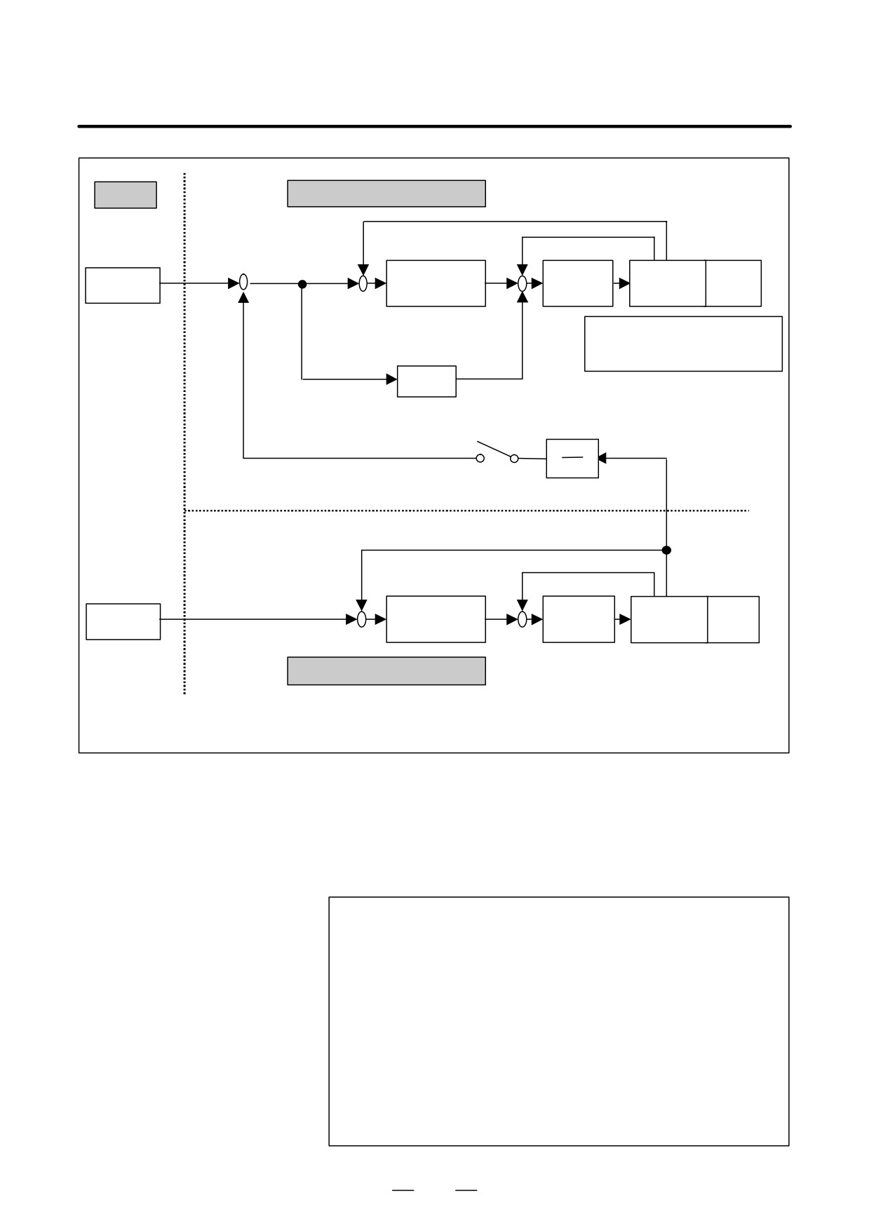
In the Spindle EGB, the synchronous pulse is produced from the feedback
pulse of the position detector attached to the tool axis (master axis) in the
motor control, and the workpiece axis (slave axis) rotates with the pulse.
Feedback pulse from Master side to Slave side is forwarded by the
communication between spindle amplifiers.
The specifications of the Spindle EGB control are as follows:
1) The Spindle EGB synchronization is started by specifying T
command (number of teeth) and L command (number of hob threads),
which determine the synchronous ratio, in G81 block. The Spindle
EGB synchronization is canceled by specifying G80.
2) The synchronous ratio is calculated from T and L command in G81
block and the number of position detector pulses per rotation about
the tool and the workpiece axis (parameter setting).
3) This function has the retract function like the hobbing function.
4) The cutting helical gear is performed by specifying Q command
(module or diametral pitch) and P command (gear helix angle) in G81
block.
5) The Spindle EGB synchronization is maintained regardless of
whether the operation is automatic or manual.
559
20. AXIS CONTROL FUNCTIONS
PROGRAMMING
B-63534EN/02
CNC
2nd spindle (Slave)
Position feedback
Velocity feedback
-
-
ÔÔÔÔÔ
ÔÔÔÔÔ
ÔÔÔÔÔÔÔÔÔÔ
+
+
Position
+
uilt-in
ork-
elocity
Cs
motor &
piece
Ô
ÔÔ
ÔÔÔcontrolÔÔ
control (PI)
ommand
osition gain
etector
ear)
Ô
+
+
ÔÔÔÔ
ÔK2/K1 : Synchronous ratioÔÔ
Ôα : Feedforward ratioÔÔÔÔ
ÔÔαsÔÔ
ÔÔÔÔÔÔÔÔÔ
ÔÔÔÔ
EGB mode
ÔÔÔ
ÔÔÔÔK1ÔÔK2
ÔÔÔ
Position feedback
Velocity feedback
–
-
ÔÔÔÔÔ
ÔÔPositionÔÔ
ÔÔÔÔ
Built-in
ÔÔÔÔÔÔ
Cs
Velocity
Tool
ÔÔ
command Ô
ÔÔÔÔcontrolÔÔ
Ô
control (PI)
Ômotor &Ô(Hob)
+
Position gain
+
Detector
ÔÔÔÔÔ
ÔÔÔÔÔ
ÔÔÔÔÔÔÔÔÔÔ
1st spindle (Master)
* The master axis can use the rotation command with spindle mode.
Fig. 20.8.3 (a) Block diagram for Spindle EGB control
Explanations
Format
G81 T_ L_ Q_ P_ ;
Starts synchronization.
G80 ;
Cancels synchronization.
T : Number of teeth (Specifiable range : 1 to 1000)
L : Number of hob threads (Specifiable range : -200 to 200 with 0
excluded)
Q: Module or diametral pitch
Specify a module in the case of metric input.
(Unit : 0.00001mm, Specifiable range : 0.01 to 25.0mm)
Specify a diametral in the case of inch input.
(Unit : 0.00001inch-1, Specifiable range : 0.01 to 25.0inch-1)
P : Gear helix angle
(Unit : 0.0001deg, Specifiable range : -90.0 to 90.0deg)
560
B-63534EN/02
PROGRAMMING
20. AXIS CONTROL FUNCTIONS
NOTE
Specify G81 and G80 code only in a block.
D Parameter setting
The following parameters should be set for the Spindle EGB control.
(1) Master axis number (Parameter No.7771) * Only Cs contour axis
(2) Slave axis number (Parameter No.7710)
(3) Number of position detector pulses per rotation about master axis
(Parameter No.7772)
(4) Number of position detector pulses per rotation about slave axis
(Parameter No.7773)
(5) Spindle EGB master axis enable (Parameter No.4352#7)
(6) Spindle EGB slave axis enable (Parameter No.4352#6)
(7) Number of sinusoidal waves from master spindle position
detector(Parameter No.4386)
NOTE
The master axis number should be set smaller than the
slave axis number.
D Starting/canceling of
When the rotation of the tool axis (master axis) starts after G81 is
synchronization
specified, the EGB synchronization starts with the synchronous
relationship specified in G81 block, and the rotation of the workpiece axis
(slave axis) starts. When the EGB synchronization starts, the
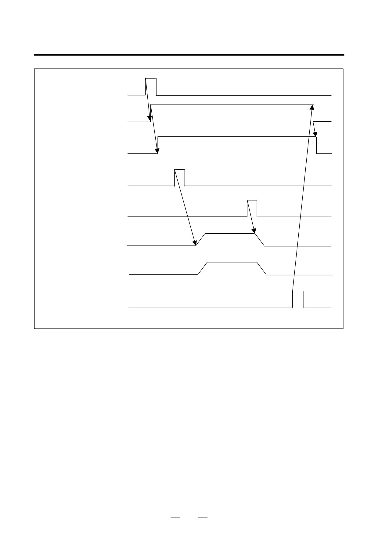
synchronization mode signal SYNMOD<F65#6> is turned to “1”.
When the rotation of the tool axis is stopped, the workpiece axis stopped
in synchronism. Then the EGB synchronization is canceled by specifying
G80. When the EGB synchronization is canceled, the synchronization
mode signal SYNMOD<F65#6> is turned to “0”.
G81 cannot be specified again during the EGB synchronization.
Moreover, the specification of T, L, Q, and P cannot be modified during
the synchronization. Specify the starting and canceling of
synchronization at the tool axis (master axis) stopping.
561
20. AXIS CONTROL FUNCTIONS
PROGRAMMING
B-63534EN/02
Synchronization start
command (G81)
Synchronizationmode
Synchronization mode signal
SYNMOD<F65#6>
Tool axis rotation command
Tool axis stop command
Tool axis rotation speed
Work piece axis rotation
speed
Synchronization cancel
command (G80)
Fig. 20.8.3 (b) Example timing for starting/canceling synchronization
Program example
O1000 ;
N00010 G80 ;
N00020 G28 G91 B0 C0 ; Performs reference position return
operation of the tool and the workpiece
axis.
N00030 G81 T20 L1 ;
Starts synchronization.
N00040 Mxx ;
Rotates the tool axis by velocity
command of PMC axis control.
N00050 G04 X1000 ;
Waits until rotation of the tool axis is
constant.
N00060 G01 X_ F_ ;
Makes movement on the X-axis(for
cutting).
N00070 G01 Z_ F_ ;
Makes movement on the Z-axis(for
machining).
- - - - - - - - - - - - ;
- - - - - - - - - - - - ;
562
B-63534EN/02
PROGRAMMING
20. AXIS CONTROL FUNCTIONS
N00100 G01 X_ F_ ;
Makes movement on the X-axis(for
retraction).
N00110 Myy ;
Stops the tool axis.
N00120 G80 ;
Cancels synchronization.
N00130 M30 ;
Helical gear
When a helical gear is to be produced, the compensation of the workpiece
compensation
axis rotation is needed according to the travel distance on the Z-axis (axial
feed axis: parameter No. 7709 setting). Helical gear compensation is
performed by adding compensation pulses calculated from the formula
below to the workpiece axis.
sin(P)
Compensation angle
+ Z
360
(For metric input)
p T Q
or
Compensation angle +Z Q sin(P)
360 (For inch input)
p T
where
Compensation angle : Signed absolute value (deg)
Z: Amount of travel on the Z-axis after the specification of G81 (mm
or inch)
P : Signed gear helix angle (deg)
T: Number of teeth
Q: Module (mm) or diametral pitch (inch-1)
The values of P, T, Q, are to be programmed.
In helical gear compensation, the machine coordinates and absolute
coordinates of the workpiece axis are updated by the amount of helical
gear compensation. When P command and Q command are not specified
in G81 block, helical gear compensation is not performed.
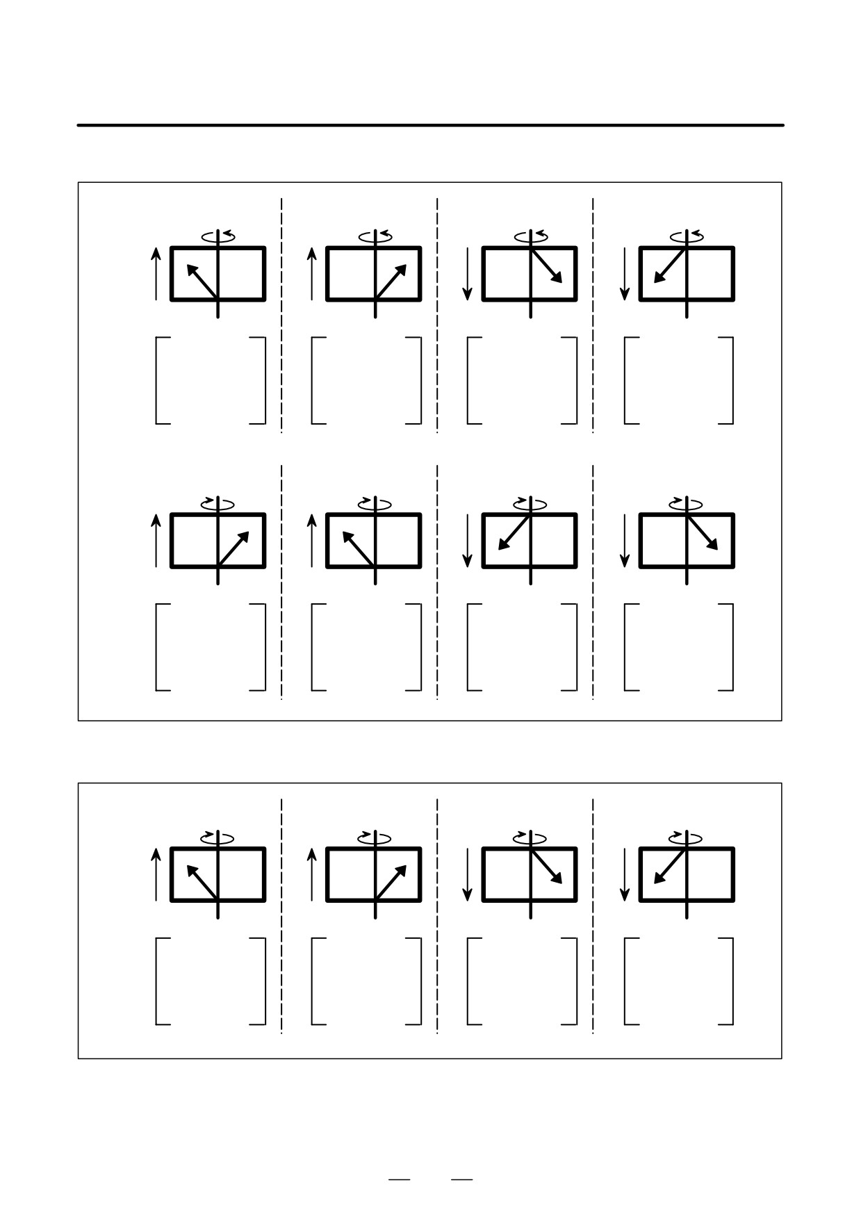
The direction of helical gear compensation is determined by bit 2 (HDR)
of parameter No.7700
(1 is usually specified). The compensation
direction is shown in figure 2.4.
563
20. AXIS CONTROL FUNCTIONS
PROGRAMMING
B-63534EN/02
(1) When bit 2 (HDR) of parameter No.7700 is 1.
(a)
(b)
(c)
(d)
+Z
+C
+Z
+C
+Z
+C
+Z
+C
- Z
- Z
- Z
- Z
C :
+
C :
+
C :
+
C :
+
Z :
+
Z :
+
Z :
-
Z :
-
P :
+
P :
-
P :
+
P :
-
Cmp. direc. :
+
Cmp. direc. :
-
Cmp. direc. :
-
Cmp. direc. :
+
(e)
(f)
(g)
(h)
+Z
- C
+Z
- C
+Z
- C
+Z
- C
- Z
- Z
- Z
- Z
C :
-
C :
-
C :
-
C :
-
Z :
+
Z :
+
Z :
-
Z :
-
P :
+
P :
-
P :
+
P :
-
Cmp. direc. :
-
Cmp. direc. :
+
Cmp. direc. :
+
Cmp. direc. :
-
(2) When bit 2 (HDR) of parameter No.7700 is 0. (Items (a) to (d) are the
same as for (1))
(e)
(f)
(g)
(h)
+Z
- C
+Z
- C
+Z
- C
+Z
- C
- Z
- Z
- Z
- Z
C :
-
C :
-
C :
-
C :
-
Z :
+
Z :
+
Z :
-
Z :
-
P :
+
P :
-
P :
+
P :
-
Cmp. direc
:
+
Cmp. direc. :
-
Cmp. direc. :
-
Cmp. direc. :
+
Fig. 20.8.3 (c) Direction of helical gear compensation
564
B-63534EN/02
PROGRAMMING
20. AXIS CONTROL FUNCTIONS
D Synchronous ratio
The synchronous ratio of the Spindle EGB control is internally
represented using a fraction. The fraction is calculated from T and L
command in G81 block and the number of position detector pulses per
rotation about the tool and the workpiece axis (parameter setting).
Synchronous ratio : K2
K1+T a
L: Hob threads
T: Number of teeth of the work
a: Number of position detector pulses per revolution about the tool
axis (Parameter No.7772)
b : Number of position detector pulses per revolution about the
workpiece axis (Parameter No.7773)
This synchronous ratio is reduced to the lowest term, and it has the
following limit.
-32767 < K2 < 32767
1 < K1 < 65535
When K2 or K1 is out of this range, P/S alarm (No.181) occurs.
The values of K2 and K1 are set to the parameter No.4387 and No.4388
automatically when G81 is specified. If T is not specified in G81 block,
P/S alarm (No.181) occurs. If L is not specified in G81 block, the
synchronous ratio is calculated as L = 1.
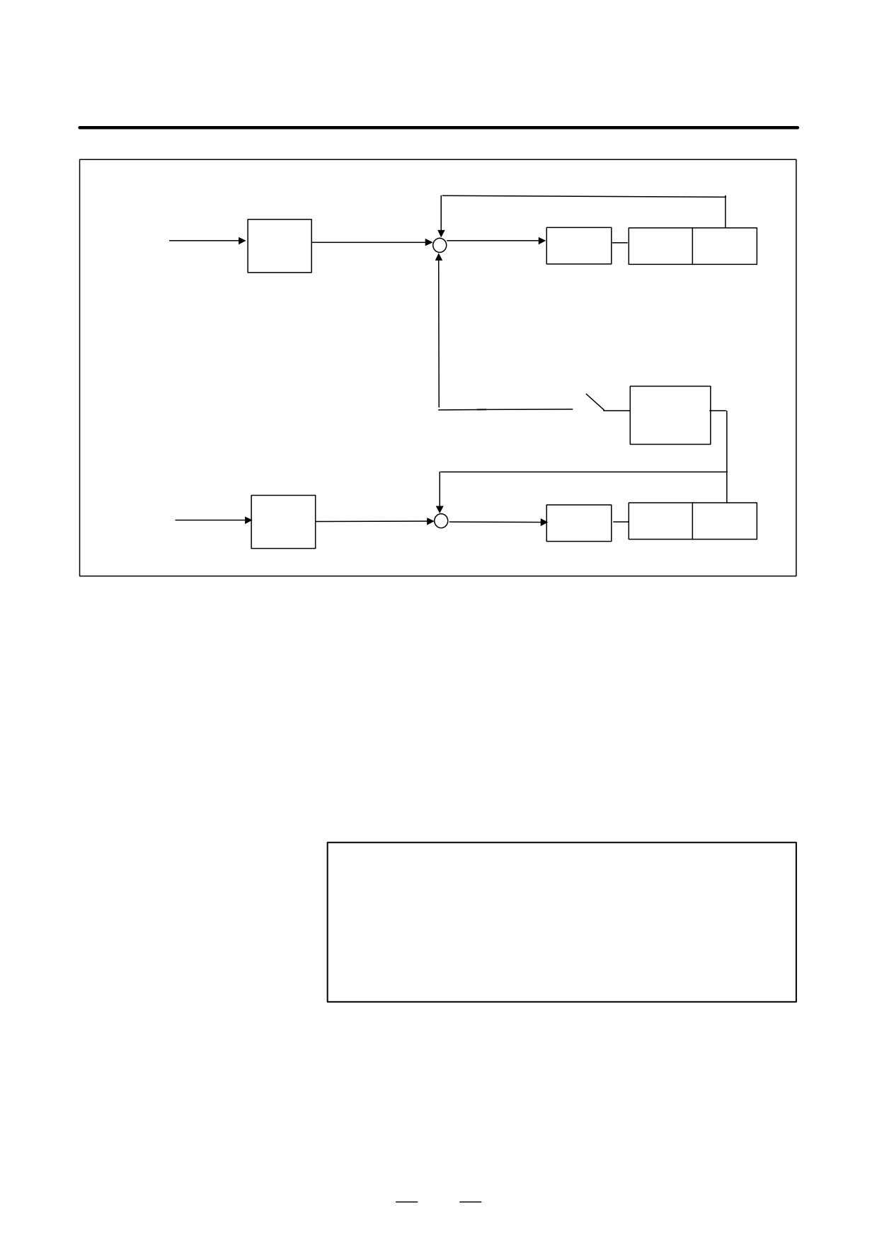
Example) When the pulses for one rotation (360000) are specified to the
tool axis (master axis) on the following conditions, the pulses for position
control are distributed as Fig.20.8.3(d).
Hob threads L : 10
Number of teeth of the work T : 100
Number of pulse per one revolution of position detector on the tool
axis a : 360000
Number of pulse per one revolution of position detector on the work
axis b : 360000
360000
Synchronous ratio : K2
K1+T a
100
360000
10
565
20. AXIS CONTROL FUNCTIONS
PROGRAMMING
B-63534EN/02
Position feedback
0
-
36000
Slave axis
*CMR
Cs command
0
Motor
Workpiece
Detector
(*1)
+
+
K2/K1 : Synchronous ratio
EGB
*K2/K1
(*1/10)
36000
360000
-
+
Master axis
*CMR
Tool axis
Detector
(*1)
Motor
Cs command
360000
360000
Fig. 20.8.3 (d) Pulse distribution
As Fig. 20.8.3 (d), when 360000 pulses (Number of pulse for one rotation
of the master axis) are specified, the pulses for slave axis by EGB are equal
to the value which is multiplied to the number of pulse for one rotation
of the slave axis by the ratio of Hob thread and number of teeth (rotation
ratio between master axis and slave axis).
360000
1/10 = 36000
D Retract function
When the retract signal RTRCT<G66#4> is turned to “1” in auto mode
(MEM, MDI, etc.) or manual mode (HNDL, JOG etc.), the axis set in bit
0 (RTR) of the parameter No.7730 moves (retracts) by the amount set in
the parameter No.7741.
NOTE
1
Feedrate in retract is set to the parameter No.7740. Then
the feedrate override is not effective.
2
During the movement in retract, feed hold is not effective.
3
In case that retract signal is turned to “1” in auto mode, the
movement of the auto mode is hold and the retract
movement is done.
Limitations
1) The EGB synchronization is not canceled by RESET when bit 0
(HBR) of parameter No.7700 is set to 1. Set 1 to this parameter
usually.
2) The EGB synchronization performed even under the following
operation of the slave axis.
566
B-63534EN/02
PROGRAMMING
20. AXIS CONTROL FUNCTIONS
– Interlock
- Feed hold
- Machine lock
3)
The EGB synchronization should be started and canceled at the stop
of the master and the slave axis. It means that the tool axis (master
axis) rotation should be started while the synchronization mode
signal SYNMOD<F065#6> is “1” (Refer to Fig.2.3 Example timing
for starting/canceling synchronization). If the tool axis (master axis)
starts to rotate before the synchronization mode signal
SYNMOD<F065#6> is “1”, the synchronization does not perform
correctly.
4)
Reference position return of Cs contouring control axis for master and
slave axis should be performed before G81 is specified. In the
synchronization mode, reference position return cannot be
performed. Do not change to reference position return mode in the
synchronization mode.
5)
In case that the parameters for axis setting (No.7710,7771,4352) are
not set correctly, P/S alarm (No.010) occurs when G81 specified.
6)
When G28/G27/G29G30/G30.1/G53 is specified in the synchronization
mode, P/S alarm (No.184) occurs. G28/G27/G29/G30/G30.1/G53
should not be specified in the synchronization mode.
7)
During HPCC mode with RISC, the high-speed cycle cutting, the
high-speed liner interpolation, the high-speed remote buffer A, the
high-speed remote buffer B of DNC operation, and AI contour
control, this function is not available.
8)
The slave axis position display is updated by synchronous pulse as
follows :
- Machine position display is updated.
- Absolute position display and relative position display are not
updated. When the synchronization is canceled, the pulses of the
synchronization are added to the absolute position display of the
slave axis.
9)
The rotation direction of the workpiece axis depends on the rotation
direction of the tool axis. That is, when the rotation direction of the
tool axis is positive, the rotation direction of the workpiece axis is also
positive; when the rotation direction of the tool axis is negative, the
rotation direction of the workpiece axis is also negative. However, by
specifying a negative value for L, the rotation direction of the
workpiece axis can be made opposite to the rotation direction of the
tool axis.
10)During synchronization, a move command can be programmed for
the workpiece axis. Note, however, that incremental command
programming for cutting feed must be used to specify the workpiece
axis move command.
11)The synchronization mode is canceled by servo alarm, spindle alarm,
P/S alarm (No.000), or emergency stop.
12)The synchronization is not maintained in servo off status of the slave
axis.
13)When the EGB control is used, the drilling canned cycle cannot be
used.
14)The actual feedrate is displayed without the flexible synchronous
pulse.
567
20. AXIS CONTROL FUNCTIONS
PROGRAMMING
B-63534EN/02
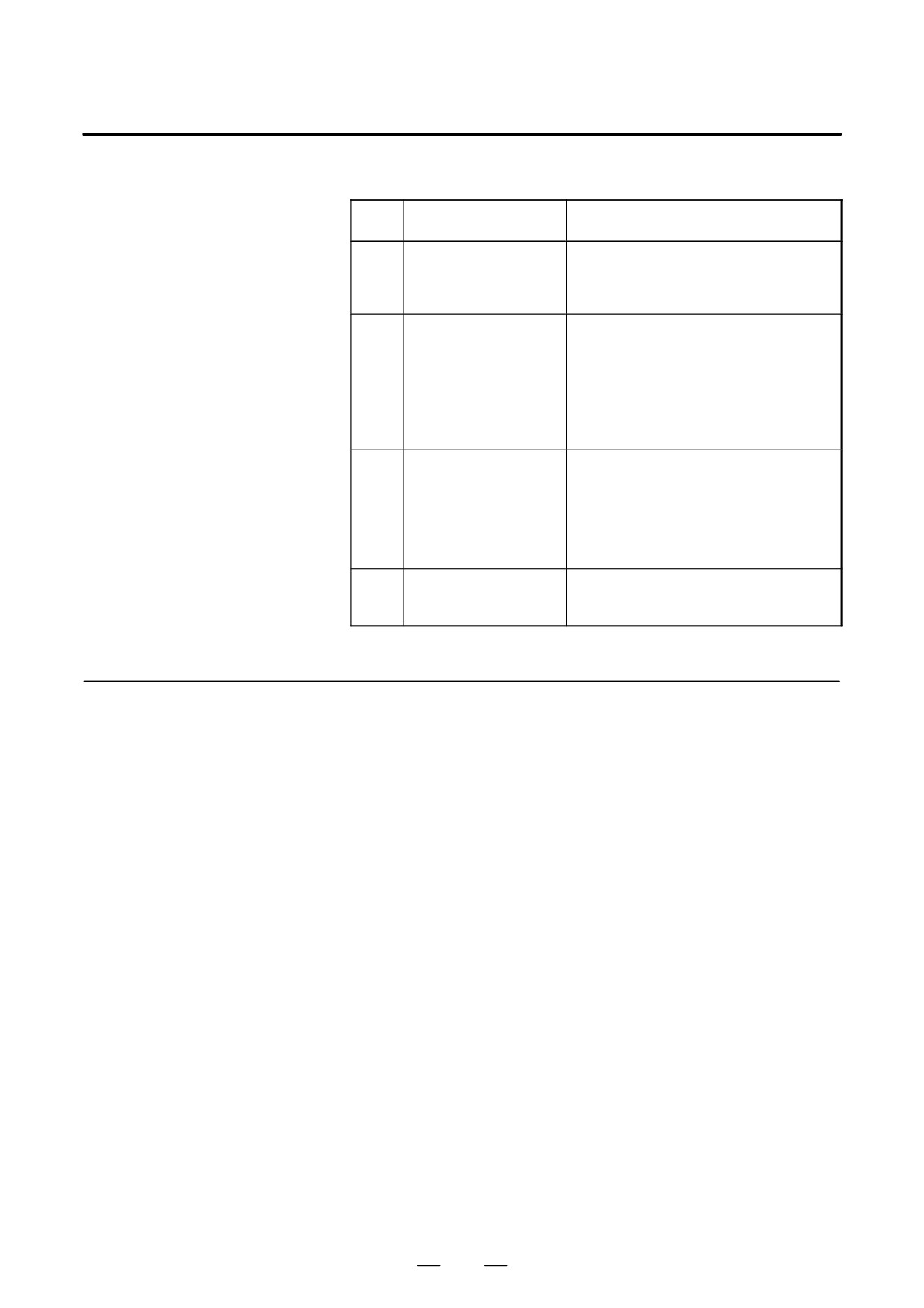
Alarms
Num-
Message
Contents
ber
010
IMPROPER G-CODE
Parameters for axis setting are not set cor-
rectly regarding G81. (No.7710,7771,4352,
or Cs axis setting).
Confirm the parameter setting.
181
FORMAT ERROR IN
G81 block format error
G81 BLOCK
1)T(number of teeth) has not been
instructed.
2)Data outside the command range was
instructed by either T, L, Q, or P.
3)Calculation of the synchronous ratio has
overflowed.
Modify the program.
184
ILLEGAL COMMAND
A command not to be instructed during
IN G81
synchronization was instructed.
1)The slave axis is specified by G00, G28,
G27, G29, G30.
2)Inch/metric conversion by G20, G21
was instructed.
3)Cs contour control mode is not selected.
186
PARAMETER SETTING
Parameter error regarding G81
ERROR
1)The slave axis has not been set to be a
rotate axis.
20.8.4
In the electronic gear box
(EGB), when synchronization start or
cancellation is specified, synchronization is not started or canceled
Electronic Gear Box
immediately.
Automatic Phase
Instead, acceleration/deceleration is executed first.
Therefore,
Synchronization
synchronization can be started or canceled while the spindle is rotating.
Also, synchronization ratio can be changed while the spindle is rotating.
At synchronization start, automatic phase synchronization is performed
such that the workpiece axis position matches the position corresponding
to the spindle one-rotation signal. With this synchronization, the same
operation is performed as synchronization start caused by a one-rotation
signal in hobbing synchronization when using the functions of a hobbing
machine.
The spindle corresponds to the EGB master axis and the workpiece axis
corresponds to an EGB slave axis (Servo axis or Cs contouring axis).
568
B-63534EN/02
PROGRAMMING
20. AXIS CONTROL FUNCTIONS
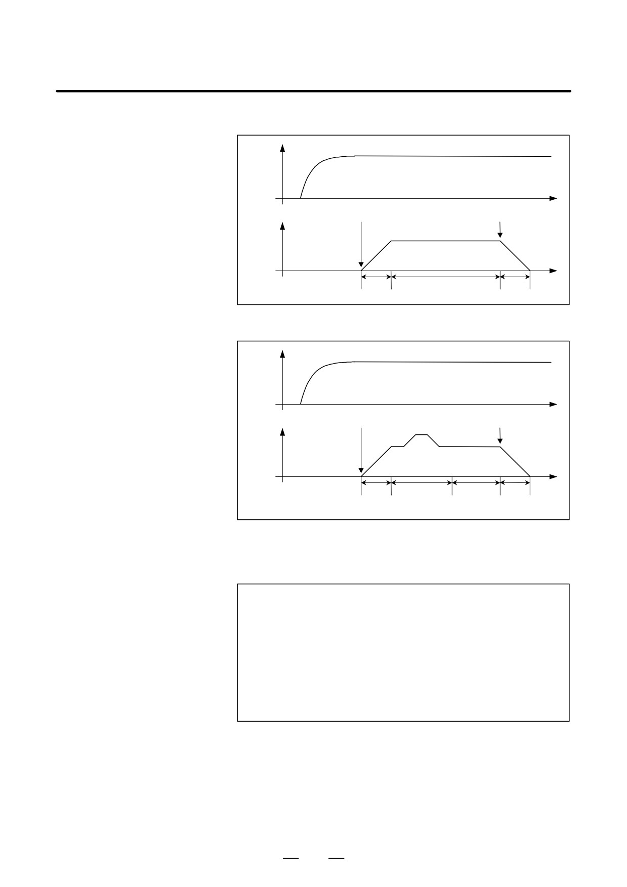
D Acceleration/deceleration
type
Spindle
speed
Synchronization
Synchronization start command
cancellation command
Workpiece-
axis speed
Synchronization
Acceleration
state
Deceleration
D Acceleration/deceleration
plus automatic phase
synchronization type
Spindle
speed
Synchronization
Synchronization start command
cancellationcommand
Workpiece-
axis speed
Automatic
Synchro-
Acceleration
phase
nization
Deceleration
synchronization
state
Format
D Acceleration/deceleration
type
G81 T_ L_ R1;
Synchronization start
G80 R1;
Synchronization end
T : Number of teeth (range of valid settings: 1-1000)
L : Number of hob threads (range of valid settings: -21 to +21,
excluding 0)
When L is positive, the direction of rotation about the workpiece
axis is positive (+ direction).
When L is negative, the direction of rotation about the workpiece
axis is negative (- direction).
569
20. AXIS CONTROL FUNCTIONS
PROGRAMMING
B-63534EN/02
D Acceleration/deceleration
plus automatic phase
synchronization type
G81 T_ L_ R2;
Synchronization start
G80 R2;
Synchronization end
T : Number of teeth (range of valid settings: 1-1000)
L : Number of hob threads (range of valid settings: -21 to +21,
excluding 0)
When L is positive, the direction of rotation about the workpiece
axis is positive (+ direction).
When L is negative, the direction of rotation about the workpiece
axis is negative (- direction).
Explanations
D Acceleration/deceleration
type
Spindle
speed
Synchronization
Synchronization start command
cancellation command
Workpiece-
axis speed
Synchronization
Acceleration
state
Deceleration
G81R1 command
execution
Acceleration
Synchronizationmode
SYNMOD
G80R1 command execution
Deceleration
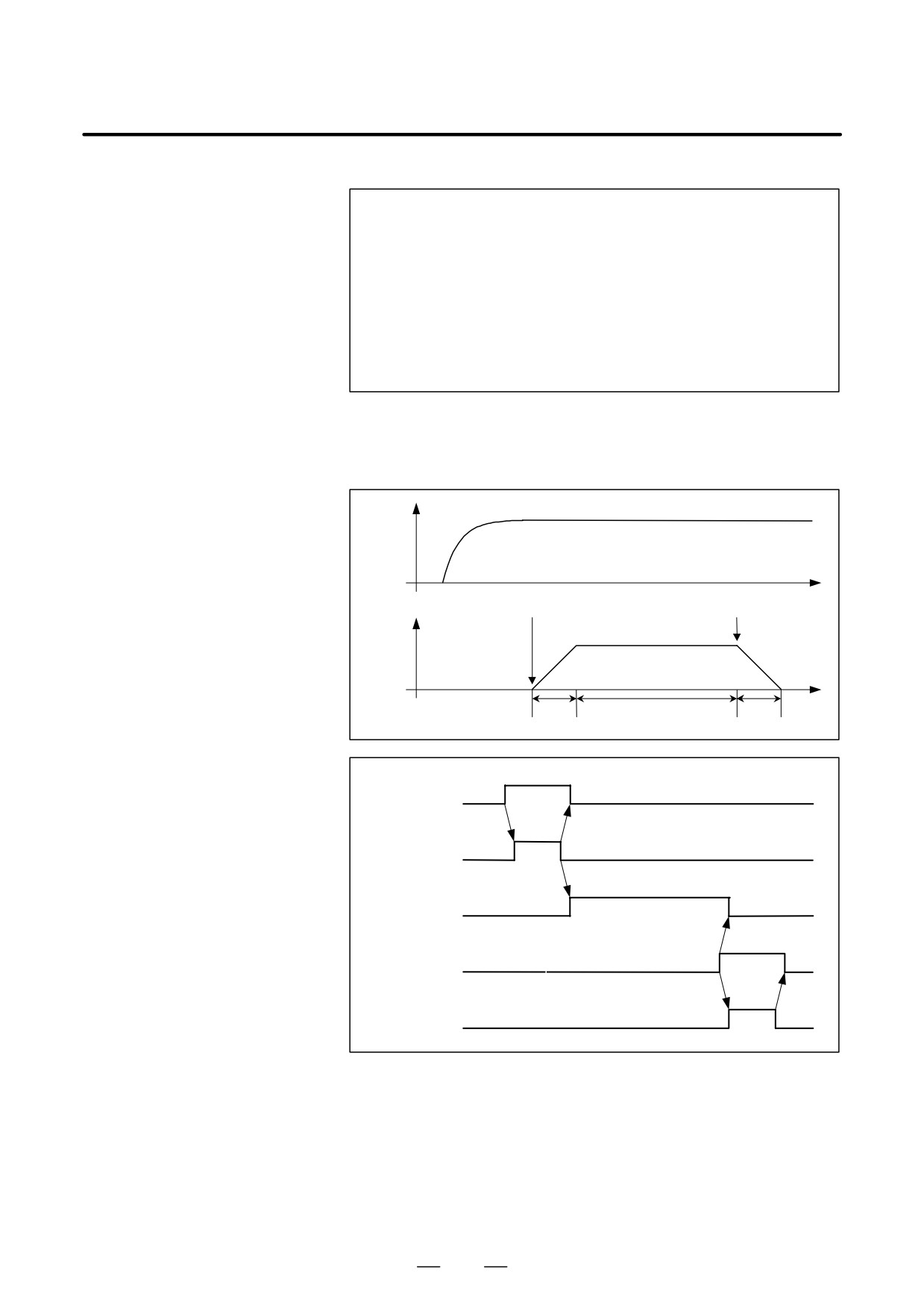
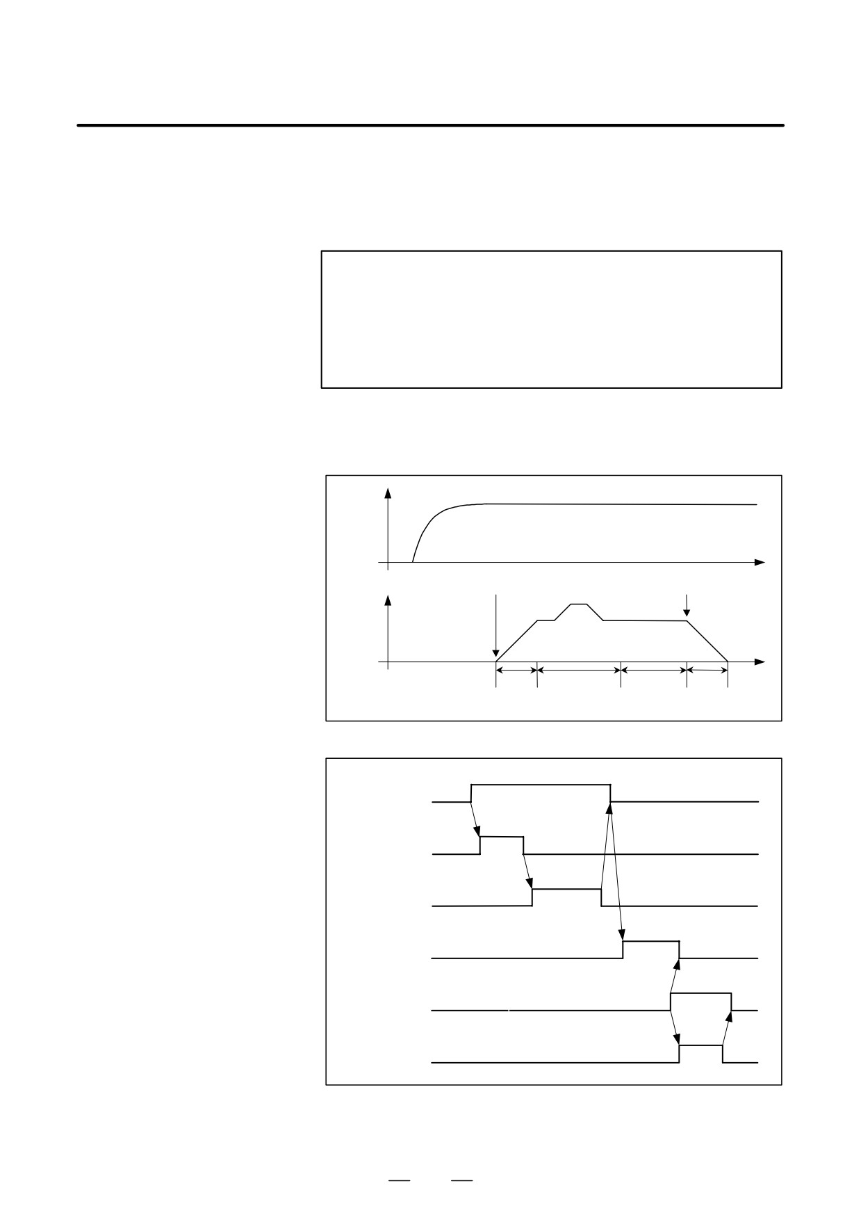
1. Specify G81R1 to start synchronization.
When G81R1 is specified, acceleration according to the acceleration
rate set in the parameter (No.2135,2136 or No.4384,4385) is performed
on the workpiece axis (slave axis). Once the synchronization feedrate is
reached, synchronization mode signal SYNMOD <F065#6> is set to 1,
and the G81R1 block is terminated.
2. For cancellation, specify G80R1 while the tool is moved away from
the workpiece.
570
B-63534EN/02
PROGRAMMING
20. AXIS CONTROL FUNCTIONS
3. When G80R1 is specified, the EGB mode check signal is set to 0, and
deceleration according to the acceleration rate set in the parameter
(No. 2135,2136 or No.4384,4385) is started immediately. When the
speed is reduced to 0, the G80R1 block is terminated.
CAUTION
1
Linear acceleration/deceleration applies to synchronization
start/cancellation.
2
In automatic synchronization cancellation due to Reset or
P/S alarm
(No.000), deceleration is executed and
synchronization is canceled.
D Acceleration/deceleration
plus automatic phase
synchronization type
Spindle
speed
Synchronization
Synchronization start command
cancellationcommand
Workpiece-
axis speed
Automatic
Synchro-
Acceleration
phase
nization
Deceleration
synchronization
state
G81R2 command
execution
Acceleration
Automatic phase synchronization
Synchronization mode signal
SYNMOD
G80R2 command execution
Deceleration
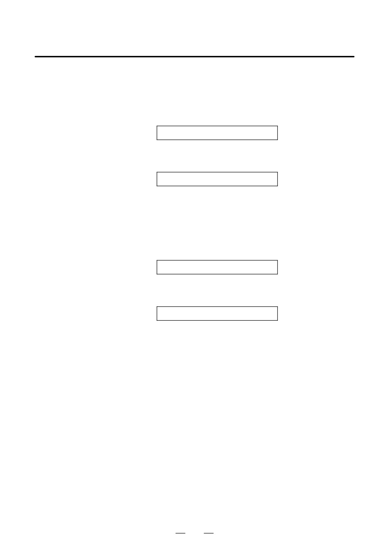
1. Move the workpiece axis to the position that corresponds to that of the
one-rotation signal of the spindle.
571
20. AXIS CONTROL FUNCTIONS
PROGRAMMING
B-63534EN/02
2. Specify G81R2 to start synchronization.
When G81R2 is specified, the workpiece axis is accelerated with the
acceleration according to the acceleration rate set in the parameter
(No.2135,2136 or No.4384,4385). When the synchronization speed is
reached, phase synchronization is performed automatically. Upon the
completion of phase synchronization, synchronization mode signal
SYNMOD <F065#6> is set to 1, and the G81R2 block is terminated.
3. For cancellation, specify G80R2 while the tool is moved away from
the workpiece.
4. When G80R2 is specified, the synchronization mode signal is set to
0, and deceleration according to the acceleration rate set in the
parameter (No.2135,2136 or No.4384,4385) is started immediately.
When the speed is reduced to 0, the G80R2 block is terminated.
572

B-63534EN/02
PROGRAMMING
20. AXIS CONTROL FUNCTIONS
CAUTION
1
In automatic phase synchronization, specify the speed in parameter No.7776 and the
movement direction in parameter PHD, bit 7 of No. 7702.
In phase synchronization, rapid-traverse linear acceleration/deceleration
(with the time
constant specified in parameter No. 1620) is performed.
The workpiece-axis speed is obtained by superposing the speed in automatic phase
synchronization onto the speed corresponding to spindle rotation.
In consideration of this superposition, specify a position deviation limit in parameter No. 1828.
2
The one-rotation signal used for automatic phase synchronization is issued not by the spindle
position coder but by the separate pulse coder attached to the spindle and used to collect EGB
feedback information. This means that the orientation position based on the one-rotation
signal issued by the spindle position coder does not match the position used as the reference
for the workpiece axis when establishing phase synchronization for automatic phase
synchronization based on G81R2.
Moreover, the one-rotation signal of the separate pulse coder must be turned on for each
rotation of the spindle.
3
With the use of parameter No.7777, the position at which the phase of the workpiece axis is
matched can be shifted from the position corresponding to the one-rotation signal in automatic
phase matching.
4
In automatic phase synchronization, when a synchronization command is issued again in a
synchronization state, movement about the workpiece axis is performed such that the position
corresponding to the one-rotation signal of the spindle matches the position about the
workpiece axis specified in the G81R2 synchronization start command executed first.
5
In automatic phase synchronization, movement is performed about the workpiece axis from the
current position to the nearest phase position in the phase synchronization movement direction
specified by the parameter.
6
Linear acceleration/deceleration applies to synchronization start/cancellation.
7
The acceleration/deceleration plus automatic phase synchronization type can be executed by
the PHS parameter, bit 6 of No.7702, without specifying an R2 command in a G81 or G80 block.
8
In automatic synchronization cancellation due to Reset or P/S alarm (No.000), deceleration is
executed and synchronization is canceled.
9
This item is for spindle EGB.
If the control mode of the master axis is the speed control, it is necessary to execute the position
coder orientation before that the automatic phase synchronization is started. In this case,
RFCHK3 (PRM4016#7) of the master axis must be set “0” to keep memorizing the one-rotation
signal position of the spindle in the speed control mode.
10
This item is for spindle EGB.
If the control mode of the master axis is Cs contouring, it is necessary to execute the reference
point return before that the automatic phase synchronization is started.
11
The acceleration rate parameter(No.2135,2136 or No.4384,4385) must not be changed in the
synchronization mode.
12
Do not cancel the synchronous mode by the reset when this function is used. (Set “1” in
patameter No.7700#0 HBR.)
573
20. AXIS CONTROL FUNCTIONS
PROGRAMMING
B-63534EN/02
Examples
D Acceleration/deceleration
type
M03 ;
Clockwise spindle rotation command
G81 T_ L_ R1 ;
Synchronization start command
G00 X_ ;
Positions the workpiece at the machining position.
Machining in the synchronous state
G00 X_ ;
Retract the workpiece from the tool.
G81 T_ L_ R1 ;
Synchronization ratio change.
G00 X_ ;
Positions the workpiece at the machining position.
Machining in the synchronous state
G00 X_ ;
Retract the workpiece from the tool.
G80 R1 ;
Synchronization cancel command
D Acceleration/deceleration
plus automatic phase
M03 ;
Clockwise spindle rotation command
synchronization type
G00 G90 C_ ;
C-axis positioning
G81 T_ L_ R2 ;
Synchronization start command
G00 X_ ;
Positions the workpiece at the machining position.
Machining in the synchronous state
G00 X_ ;
Retract the workpiece from the tool.
G81 T_ L_ R2 ;
Synchronization ratio change.
G00 X_ ;
Positions the workpiece at the machining position.
Machining in the synchronous state
G00 X_ ;
Retract the workpiece from the tool.
G80 R2 ;
Synchronization cancel command
574
B-63534EN/02
PROGRAMMING
20. AXIS CONTROL FUNCTIONS
D About the direction of
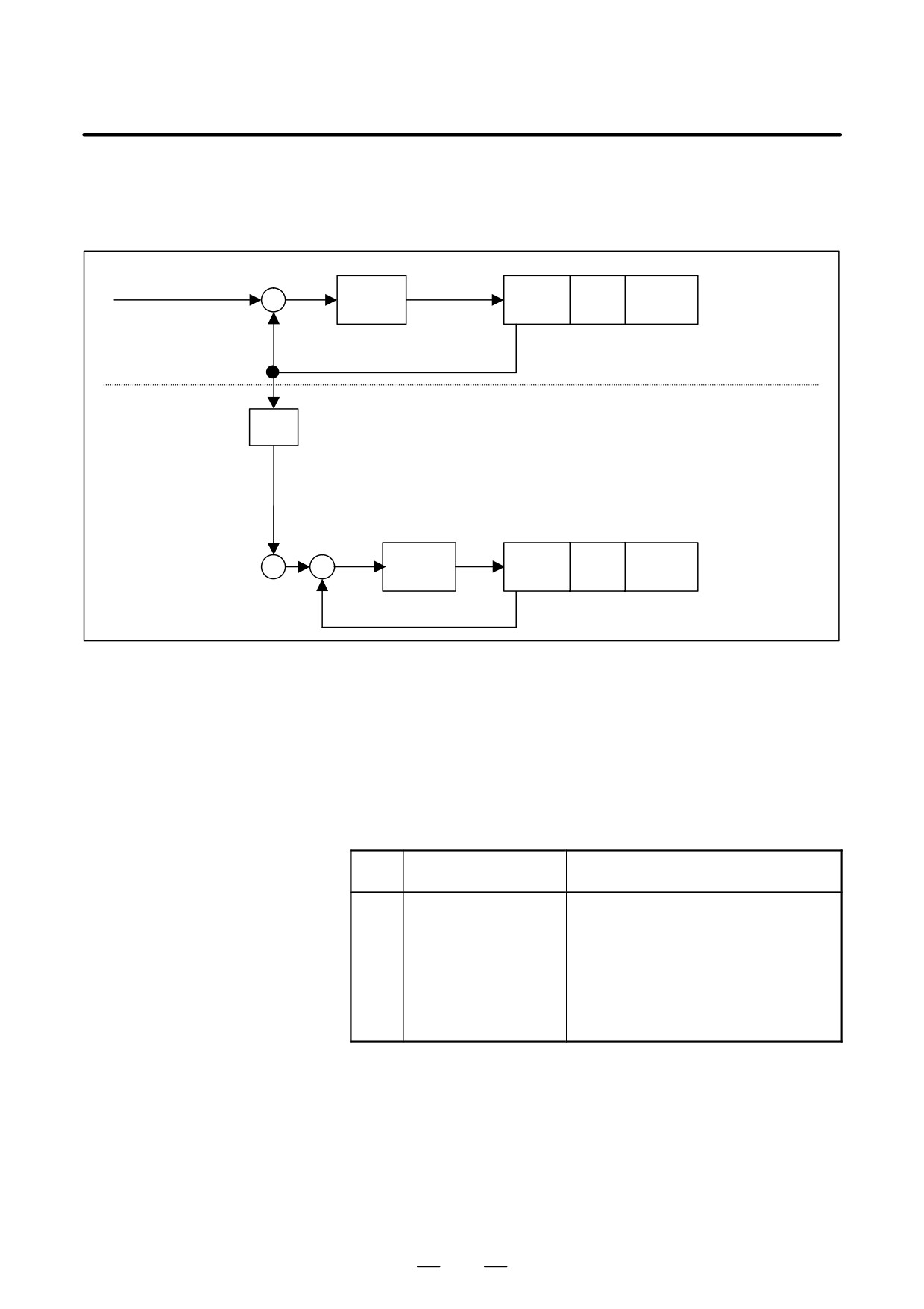
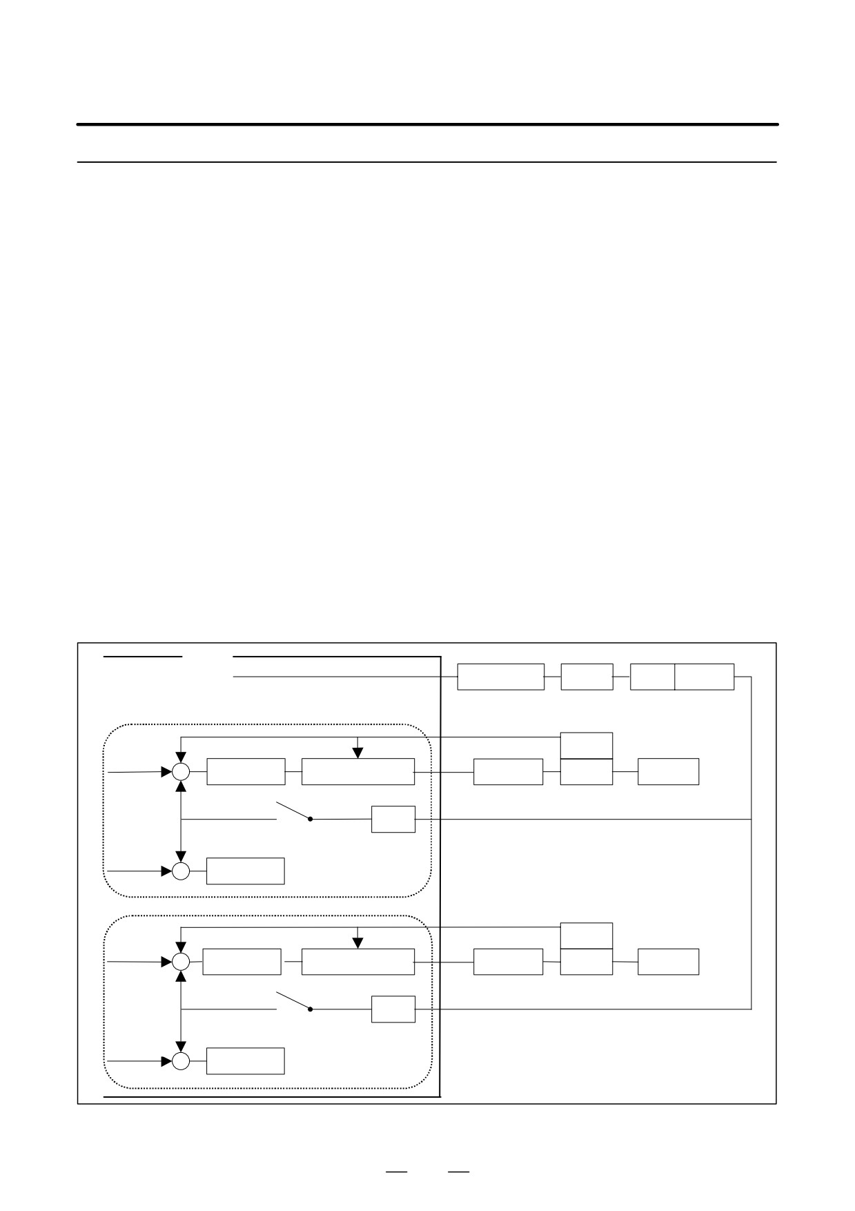
The EGB automatic phase synchronization is made on the premise that
the rotation (This item is
the rotation of the slave axis is the same direction as the master axis. Refer
for spindle EGB.)
to the following chart.
+ Command
+
+ Direction
Kp/S
Sensor
Motor
Spindle
-
[Master axis]
+ Feedback
[Slave axis]
a/A
+ EGB command
+
Kp/S
Sensor
Motor
Spindle
+ Direction
–
+ Feedback
When this function is used, the SFR/SRV function in Cs contouring mode
(*) can not use. If you want to change the rotary direction of the master
axis, you should change the sign of the master axis command.
(*) The SFR/SRV function in Cs contouring mode
The SFR/SRV signal is a serial spindle control signal that determines
the direction of rotation of the spindle in Cs contouring mode.
Alarms
Num-
Message
Contents
ber
181
EGB AUTO PHASE
Format error in block in which G80 or G81
FORMAT ERROR
was specified by EGB automatic phase
synchronization
(1) R is data outside of the instruction
range.
(2) Before the G81R2 command, the
master spindle isn’t returned to in the
reference point. (In case of Spindle
EGB)
575
20. AXIS CONTROL FUNCTIONS
PROGRAMMING
B-63534EN/02
20.8.5
Electronic Gear Box 2
Pair
General
The Electronic Gear Box is a function for rotating a workpiece in sync with
a rotating tool, or to move a tool in sync with a rotating workpiece. With this
function, the high-precision machining of gears, threads, and the like can be
implemented. A desired synchronization ratio can be programmed.
Up to two sets of axes can be synchronized. A gear grinding machine can
be controlled, for instance, by using one axis for rotating the workpiece in
sync with the tool and another axis for performing dressing in sync with the
tool.
The electronic gear box is hereinafter called an EGB function.
D Configuration examples
Spindle
: EGB master axis serving as a tool axis
of controlled axes
First axis
: X
Second axis
: Y
Third axis
: C axis (EGB slave axis serving as a workpiece axis)
Fourth axis
: C axis (EGB dummy axis, which cannot be used as a usual
controlled axis)
Fifth axis
: V axis (EGB slave axis serving as a dressing axis)
Sixth axis
: V axis (EGB dummy axis, which cannot be used as a usual
controlled axis)
CNC
Spindle (master axis)
Spindle
Motor
Spindle
Detector
amplifier
First axis X (omitted)
Tool axis
Second axis Y (omitted)
Third axis
-
Detector
Slave axis
Position
Speed/current
Servo
Motor
C-axis
+
control
control
amplifier
C
+
EGB
Workpiece axis
K1
Fourth axis
Synchronization
-
switch
Dummy axis
K1 : Synchronization factor
Follow-up
Error counter
+
Fifth axis
-
Detector
Slave axis
Position
Speed/current
Servo
Motor
V-axis
+
control
control
amplifier
V
+
EGB
Dressing axis
K2
Sixth axis
Synchronization
-
Dummy axis
switch
K2 : Synchronization factor
Follow-up
Error counter
+
Fig.20.8.5
576
B-63534EN/02
PROGRAMMING
20. AXIS CONTROL FUNCTIONS
NOTE
A sampling period of 1 ms is applied when feedback pulses
are read from the master axis; the synchronization pulses
for a slave axis are calculated according to synchronization
coefficient K; and the pulses are specified for position
control of the slave axis.
Explanations
D Synchronization start
When the ratio of the master-axis travel to the slave-axis travel is
specified, synchronization starts.
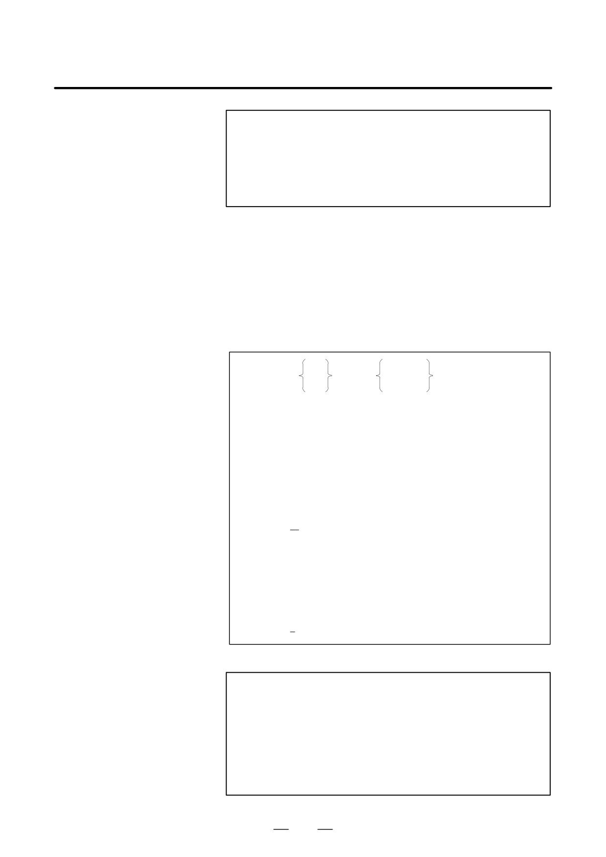
Format
T t
bj
G81.5
;
P p
b 0 L l
Master-axis travel Slave-axis travel
Specify the master-axis travel in either of the following ways.
1. Master-axis speed
T t
: Master-axis speed (1 v t v 1000)
2. Master-axis pulse count
P p : Master-axis pulse count (1 v p v 999999999)
Specify a pulse count on the condition that four pulses
correspond to one period in the A and B phases.
Specify the slave-axis travel in either of the following ways.
1. Slave-axis travel
bj b : Slave-axis address
j
: Slave-axis travel indicated in units of the minimum
travel increments
(the range of valid settings for usual axis movement
applies)
When j = 0, the specified command is regarded as
being a command for the slave-axis speed,
described below. In this case, if L is not specified, an
alarm is output.
2. Slave-axis speed
b 0 L"l b : Slave-axis address
l
: Slave axis speed (1 v l v 21)
CAUTION
1
A move command can be issued by a program to the slave
axis or other axes during synchronization. In this case, the
command shall be an incremental command.
2
A G00, G27, G28, G29, G30, G30.1,G33 or G53 command
cannot be issued to the slave axis in synchronization mode.
3
Controlled-axis detach cannot be used for the master axis
or the slave axis.
577
20. AXIS CONTROL FUNCTIONS
PROGRAMMING
B-63534EN/02
NOTE
1
A manual handle interruption can be issued to the slave axis
or other axes during synchronization.
2
The maximum feedrates for the master axis and the slave
axis are limited according to the position detectors used.
3
An inch/metric conversion command (G20 or G21) cannot
be specified in synchronization mode.
4
The machine coordinates for the slave/dummy axis are
updated in synchronization mode.
D Synchronization end
Format
With a G80.5 b 0 command, synchronization is canceled.
b is the address of the slave axis.
1.
Canceling synchronization for each axis by issuing a command
Synchronization of the slave axis specified by ? is canceled.
A cancellation command can be issued only for one axis in one block.
When b 0 is not specified, the synchronization of all currently
synchronized axes is canceled.
When a synchronization cancellation command is issued, the absolute
coordinates for the slave axis are updated according to the amount of
travel during synchronization. For a rotation axis, the value obtained
by rounding off the amount of travel during synchronization to the
nearest 360 degrees is added to the absolute coordinates.
2.
Canceling synchronization by a reset
For an axis for which a parameter is set to allow synchronization to be
canceled by a reset, HBR, bit 0 of No. 7700, is set to 0, allowing
synchronization to be canceled by a reset. When a manual absolute
signal is on, the absolute coordinates are updated.
3.
Others
Synchronization is automatically canceled under the following
conditions.
(1) Emergency stop
(2) Servo alarm
(3) P/S alarm No.000 (indicating that the power should be
turned off)
D Description of
A command compatible with that for a hobbing machine can be used as
commands compatible
a synchronization command.
with those for a hobbing
Such a command cannot be used when a canned-cycle option is provided.
machine
Specify which axes starts synchronization with such a command by using
parameter No. 7710.
(1) Synchronization start
When the following command is specified, synchronization of spindle
axis and C axis starts
578

B-63534EN/02
PROGRAMMING
20. AXIS CONTROL FUNCTIONS
G81 T_(L_)(Q_P_);
T : Number of teeth (range of valid settings: 1 to 1000)
L : Number of hob threads (range of valid settings: -21 to +21,
excluding 0)
The sign of L determines the direction of rotation
for the workpiece axis.
When L is positive, the direction of rotation for the workpiece
axis is positive (+ direction).
When L is negative, the direction of rotation for the workpiece
axis is negative (- direction).
When L is not specified, the number of hob threads is regarded
as being 1.
Q: Module or diametral pitch
In metric input, specify a module
(unit : 0.00001 mm, range of valid settings : 0.1 to 25.0 mm).
In inch input, specify a diametral pitch
(unit : 0.00001 [1/inch], range of valid settings: 0.1 to 254.0 [1/inch])
P : Twisted angle of a gear
(unit : 0.00001 degrees, range of valid settings : -90.0 to 90.0
degrees)
Specify P and Q to use helical gear compensation. In this case, if only one
of P and Q is specified, an alarm (P/S 181) is generated.
The decimal point can be specified in Q and P.
When a G81 command is issued to change to synchronization mode, the
EGB mode confirmation signal for the workpiece axis becomes “1” and
synchronization starts between the spindle and the workpiece axis.
During synchronization, control is performed such that the ratio of the
spindle speed to the workpiece-axis speed is the same as that of T
(number of teeth) to L (number of hob threads).
When a G81 command is again specified during synchronization without
canceling synchronization, an alarm (P/S 181) is generated.
(2) Synchronization end
When the following command is specified, sysnchronization is
cancelled.
G80;
Synchronization of all synchronized axes is canceled.
When a synchronization cancellation command is issued, the absolute
coordinates for the slave axis are updated according to the amount of
travel during synchronization.
For a rotation axis, the value obtained by rounding off the amount of
travel during synchronization to the nearest 360 degrees is added to the
absolute coordinates.
In a G80 block, do not specify addresses other than O or N.
(3) Helical gear compensation
For a helical gear, the workpiece axis is subjected to compensation for
movement along the Z axis (axial feed axis) according to the twisted
angle of the gear.
Helical gear compensation is performed with the following data.
Z sin(P)
Compensation angle +
360 (In metric input)
p T Q
579