FANUC Series 16i/160i/160is-MB, Series 18i/180i/180is-MB5, Series 18i/180i/180is-MB. Operator's Manual - page 22
22. RISC PROCESSOR
PROGRAMMING
B-63534EN/02
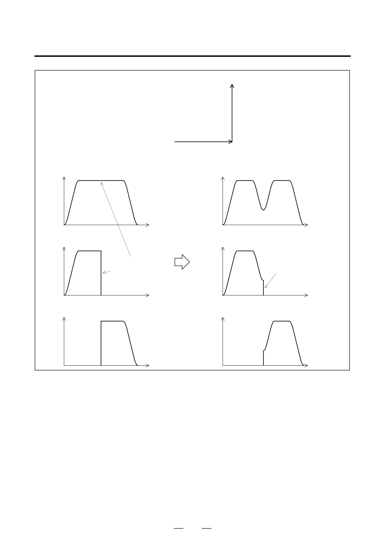
D Method of determining
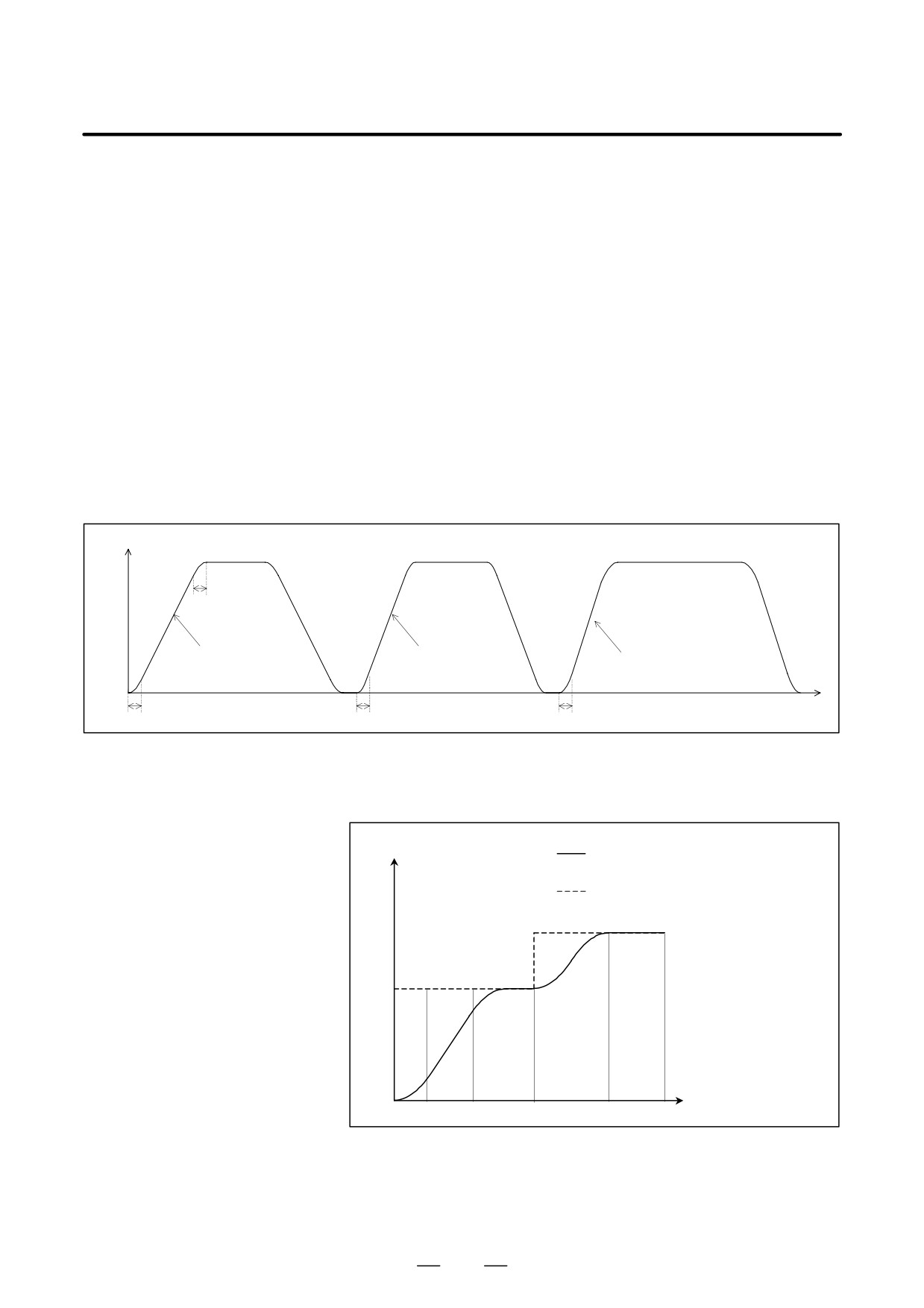
Acceleration/deceleration is performed with the largest tangent
the tangent acceleration
acceleration/deceleration that does not exceed the acceleration set for
each axis.
(Example)
X-axis permissible acceleration:
1000 mm/sec2
Y-axis permissible acceleration:
1200 mm/sec2
Acceleration change time: 20 msec
Program:
N1 G01 G91 X20. F6000
Move on the X-axis.
G04 X0.01
N2 Y20.
Move on the Y-axis.
G04 X0.01
N3 X20. Y20.
Move in the XY direction (at 45 degrees).
The acceleration in N3 is 1414 mm/sec2 . At this point, the acceleration
on the X-axis is equal to the set value (1000 mm/sec2 ).
Tangent feedrate
20ms
1000mm/sec2
1200mm/sec2
1414mm/sec2
gradient
gradient
gradient
20ms
20ms
20ms
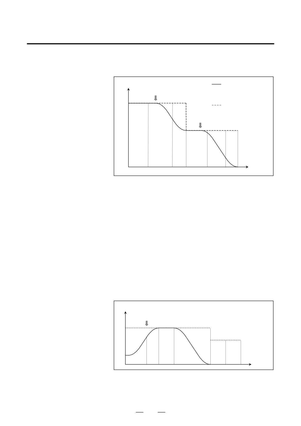
D Acceleration
Acceleration is performed so that the feedrate programmed for a block is
attained at the beginning of the block.
Feedrate
Speed control by bell-shaped acceleration/
deceleration beforeinterpolation
Programmed speed
Time
N1
N2
N3
N4
N5
610
B-63534EN/02
PROGRAMMING
22. RISC PROCESSOR
D Deceleration
Deceleration starts in advance so that the feedrate programmed for a block
is attained at the beginning of the block.
Deceleration can be performed over several blocks.
Feedrate
Speed control by
Deceleration
bell-shapedacceleration/
start point
deceleration before
interpolation
Programmed speed
Deceleration
start point
Time
D Deceleration based on a
If the total distance of the blocks read ahead becomes shorter than or equal
distance
to the deceleration distance obtained from the current feedrate,
deceleration starts.
If the total distance of the blocks read ahead during deceleration increases,
acceleration is performed.
If the blocks of a small amount of travel are successively specified,
deceleration and acceleration may be performed alternately, making the
feedrate inconsistent. To avoid this, decrease the programmed feedrate.
D Single-block commands
If a single-block command is executed during look-ahead bell-shaped
during look-ahead
acceleration/deceleration control, the following control is applied.
bell-shaped
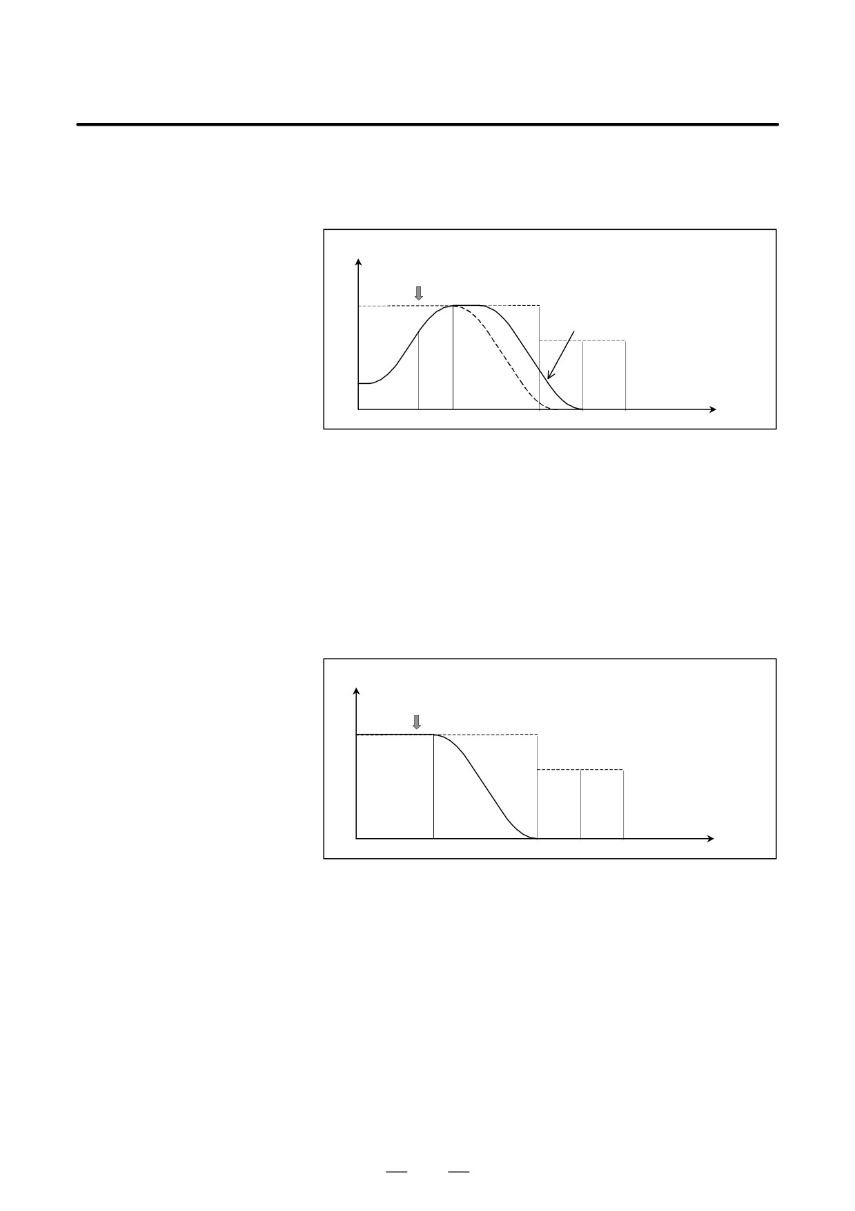
(1) If acceleration/deceleration is performed when the single-block
acceleration/deceleration
command is executed
before interpolation
(a) If A + B v Remaining amount of travel in the block executed
control
when the single-block command is executed
Deceleration is performed for a stop so that the feedrate falls to
zero at the point at which the block executed when the
single-block command was executed terminates.
Feedrate
Single-block command
##
""
### """
#A#
""
B
""
###
"""#
###
"""###
Time
A: Amount of travel to a point where the target feedrate is
attained and the current acceleration/deceleration ends
B: Amount of travel corresponding to deceleration from the
feedrate attained at the end of acceleration/deceleration to 0
611
22.
RISC PROCESSOR
PROGRAMMING
B-63534EN/02
(b) If A + B > Remaining amount of travel in the block being
executed when the single-block command is executed
A stop state may continue over several blocks.
The stop is made as described later.
Feedrate
Single-block command
%$$
Stop state continuing over multiple blocks
%%%$$
%%%$$
B$
%%A%
$
%%%$$""
Time
%%%$$"""
A: Amount of travel to a point where the target feedrate is
attained and the current acceleration/deceleration ends
B: Amount of travel corresponding to deceleration from the
feedrate attained at the end of acceleration/deceleration to 0
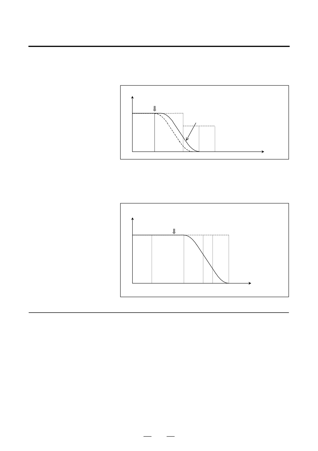
(2)
If acceleration/deceleration is not performed when the single-block
command is executed
(a) AvRemaining amount of travel in the block being executed
when the single-block command is executed
Movement is decelerated and stopped so that the feedrate falls to
zero at the end of the block which was being executed when the
single-block command was executed.
Feedrate
Single-block command
%%
%%%
%%%
A
%
%%%"
%%%"""
Time
A: Amount of travel corresponding to deceleration from the
current feedrate to 0
612
B-63534EN/02
PROGRAMMING
22. RISC PROCESSOR
(b) If A > Remaining amount of travel in the block being executed
when the single-block command is executed
A stop state may continue over several blocks.
The stop is made as described later.
Feedrate
Single-block command
##
Stop state continuing over multiple blocks
###
####
##A##
###&&
Time
###&&&
A: Amount of travel corresponding to deceleration from the
current feedrate to 0
(3) Stopping a movement if the stop may continue over several blocks
Acceleration/deceleration is performed over several blocks to
decrease the feedrate to zero.
Feedrate
Single-block command
Time
In AI High Precision Countour Control mode, the feedrate is
22.1.2
automatically controlled by the reading-ahead of blocks.
Automatic Feedrate
The feedrate is determined using the following conditions. If the
Control Function
specified feedrate exceeds the determined feedrate, acceleration/
deceleration before interpolation is performed to achieve the determined
feedrate.
(1) Feedrate changes on each axis at a corner and the permissible feedrate
change that has been set
(2) Expected acceleration on each axis and the permissible acceleration
that has been set
613
22.
RISC PROCESSOR
PROGRAMMING
B-63534EN/02
(3) Cutting load that is expected from the travel direction on the Z-axis
Specified tool path
The machining error is decreased
because of the deceleration by
Tool path assumed
difference in feedrate.
when Al High Precision
Contour Control is not
used
Tool path assumed
when Al High Precision
Contour Control is used
The machining error is decreased
because of the deceleration with
the acceleration.
Fig. 22.1.2 (a)
To enable this function, set the desired values for the following
parameters:
Parameter No. 8410:
Permissible feedrate difference used when the feedrate is to be
determined from the feedrate difference at a corner
Parameter No. 8470:
Permissible acceleration when the feedrate is to be determined
from the acceleration
For details, see the explanation of these parameters.
D Feedrate control
In automatic feedrate control mode, the feedrate is controlled as described
conditions
below:
(a) From the feedrate difference on each axis at a corner, the feedrate
in the corner is determined, and deceleration is performed to
achieve the feedrate at the corner.
(Example)
N1
Specified
Y
F
N2
X
N1
N2
N3
t
N3
(b) From the acceleration on each axis at the corners at the start and
end points of each block, the feedrate in the block is determined,
and deceleration is performed so that the feedrate in the block is
equal to or less than the determined feedrate.
(Example)
N2 N3
N1
N4
Y
Specified
feedrate
N5
X
N8
N6
N1
N2 N3 N6 N7
N8
t
N7
614

B-63534EN/02
PROGRAMMING
22. RISC PROCESSOR
(c) During descent on the Z-axis, the cutting load increases, and
override is applied according to the Z-axis descent angle.
(Example)
N1
Z
N2
Specified
feedrate
X
N1
N2
N3
t
N3
Deceleration based on
With look-ahead acceleration/deceleration before interpolation, the
the feedrate difference at
tangent feedrate is changed smoothly. Thus, no path error occurs due to
a corner
acceleration/deceleration delay. With this acceleration/declaration,
however, acceleration/deceleration is not performed for any feedrate
change on any axis that may be made where the travel direction changes.
By using the function for deceleration based on the feedrate difference at
a corner, if a feedrate change occurs on an axis at a corner, the feedrate is
determined so that any feedrate difference exceeding the permissible
feedrate difference on that axis that has been set for parameter No. 8410
does not occur, and deceleration is automatically performed.
615
22. RISC PROCESSOR
PROGRAMMING
B-63534EN/02
(Example)
Program
N1 G01 G91 X100. F5000
N2 Y100.
N2
N1
Tangent feedrate
Tangent feedrate
The deceleration
based on the feedrate
difference is used.
X-axis feedrate
X-axis feedrate
The feedrate difference becomes
The tangent feedrate is
small, and the feedrate on each
smooth, but the feedrate
axis becomes smooth.
on each axis is not.
Y-axis feedrate
Y-axis feedrate
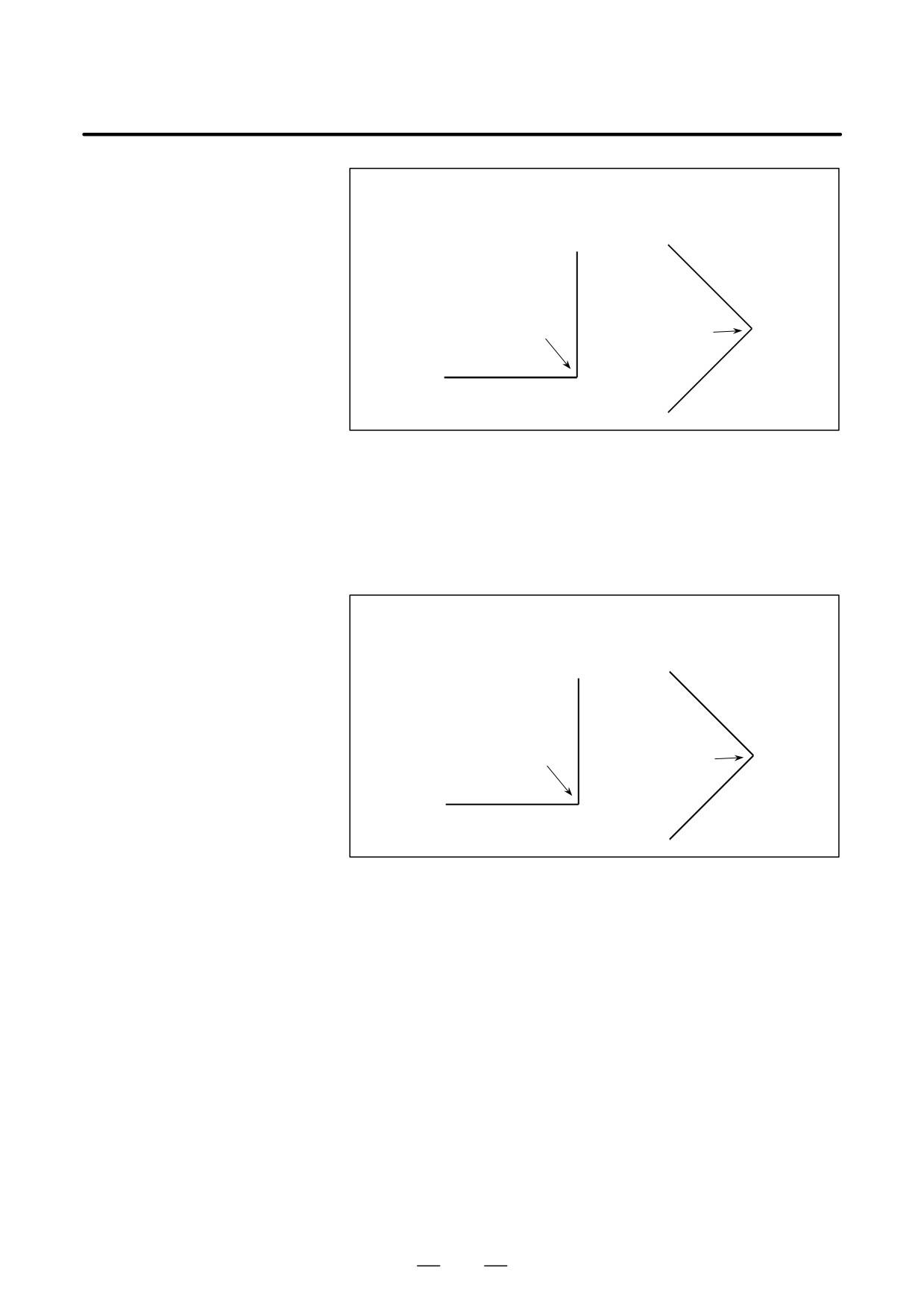
The method of deceleration based on the feedrate difference differs
depending on the setting made for parameter FNW (bit 6 of No. 19500).
If “0” is set, the largest feedrate that does not exceed the permissible
feedrate difference set for parameter No. 8410 is assumed to be the
deceleration feedrate. In this case, the deceleration feedrate differs if the
travel direction differs, even if the shape is the same.
616
B-63534EN/02
PROGRAMMING
22. RISC PROCESSOR
(Example)
If parameter FNW (bit 6 of No. 19500) = 0 and the
permissible feedrate difference = 500 mm/min (on all axes)
Deceleration to
Deceleration to
354 mm/min
500 mm/min
If “1” is set, the feedrate is determined not only with the condition that the
permissible feedrate difference and permissible acceleration on each axis
are not exceeded, but also that the deceleration feedrate is constant
regardless of the travel direction if the shape is the same.
If 1 is set for this parameter, the deceleration feedrate determined with the
feedrate difference or acceleration may be up to 30% lower than that
determined if 0 is set.
(Example)
If parameter FNW (bit 6 of No. 19500) = 1 and
permissible feedrate difference = 500 mm/min (on all axes)
Deceleration to
Deceleration to
354 mm/min
354 mm/min
Example of determining
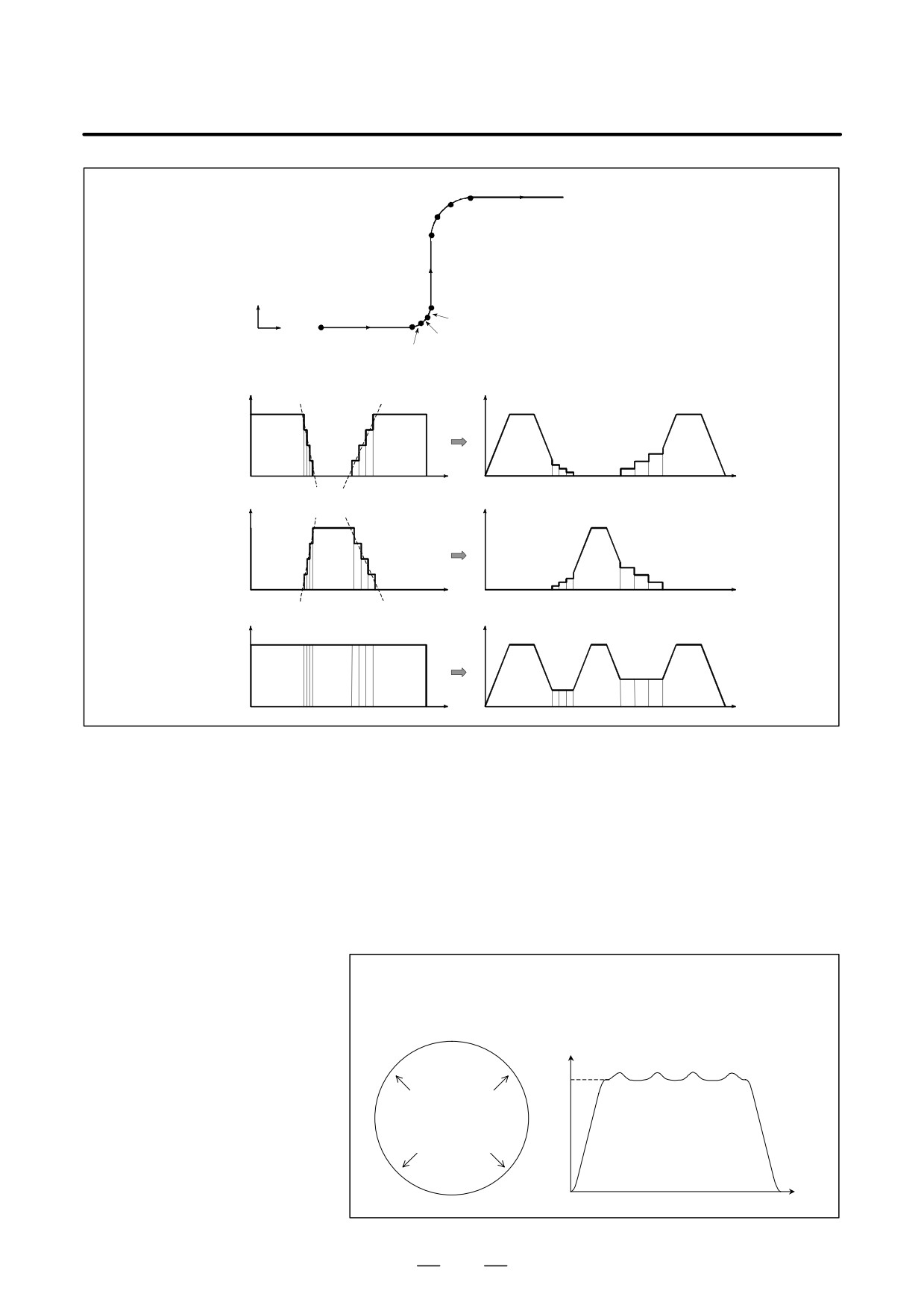
When consecutive small lines are used to form a curve, as in the example
the feedrate with the
shown in the figure below, the feedrate differences on each axis at the
individual corners are not very large. Thus, deceleration with the feedrate
acceleration on each
differences is not effective. Consecutive small feedrate differences,
axis
however, cause a large acceleration on each axis, as a whole.
In such a case, deceleration can be performed to reduce the impact on the
machine and the machining error caused by too large an acceleration. The
deceleration feedrate is determined to be the feedrate that does not cause
the acceleration on each axis to exceed the permissible acceleration set for
parameter No. 8470.
The deceleration feedrate is determined for each corner. The actual
feedrate is the smaller of the deceleration feedrate determined at the start
point of the block and that determined at the end point.
D Example
In the following example, the acceleration (gradient of the broken line in
the feedrate graph) at too large at corners N2 to N4 and N6 to N8 and,
therefore, deceleration is performed.
617
22. RISC PROCESSOR
PROGRAMMING
B-63534EN/02
N8
N7
N9
N6
N5
Y
N1
N4
X
N3
N2
X-axis
feedrate
Y-axis
feedrate
Tangent
feedrate
N1
N5
N9
N1
N5
N9
Fig. 22.1.2 (b) Example of Determining the Feedrate with the Acceleration
The method of determining the feedrate with the acceleration differs
depending on the setting of parameter FNW (bit 6 of No. 19500).
If “0” is set, the highest feedrate that does not cause the permissible
acceleration set for parameter No. 8470 to be exceeded is assumed to be
the deceleration feedrate. In this case, the deceleration feedrate differs
depending on the travel direction even if the shape is the same, as shown
in the figure below.
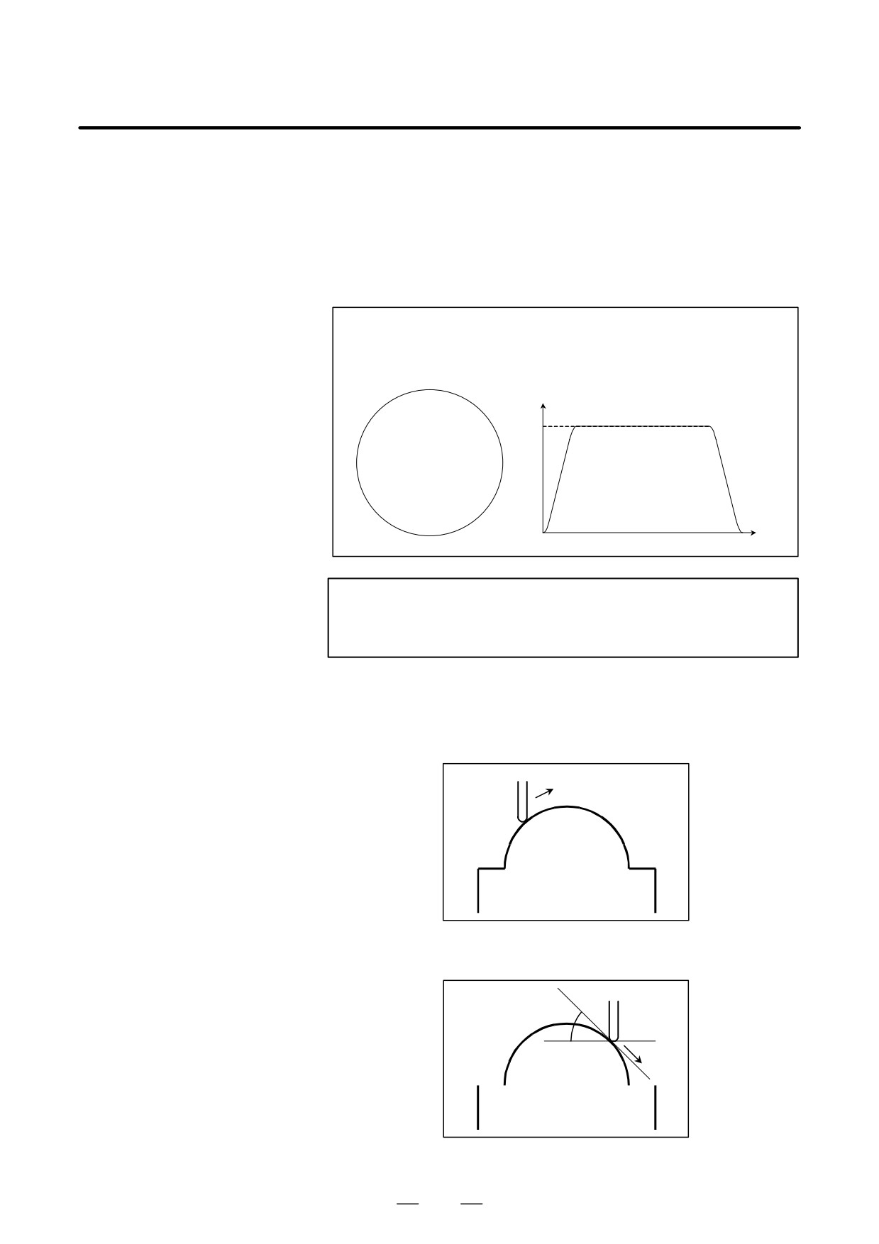
(Example)If a circular shape with a radius of 10 mm is specified
with small line blocks
Parameter FNW (bit 6 of No. 19500) = 0
Permissible acceleration = 1000 mm/s2 (on all axes)
Tangent feedrate
F6000
The feedrate is
higher in these
directions.
Time
618
B-63534EN/02
PROGRAMMING
22. RISC PROCESSOR
If “1” is set, the feedrate is determined with not only the condition that the
permissible acceleration on each axis is not exceeded but also the
condition that the deceleration feedrate is constant regardless of the travel
direction if the shape is the same.
If 1 is set for this parameter, the deceleration feedrate determined with the
feedrate difference or acceleration may be up to 30% lower than that
determined if 0 is set.
(Example)If a circular shape with a radius of 10 mm is specified
with small line blocks
Parameter FNW (bit 6 of No. 19500) = 1,
radius = 10 mm, permissible acceleration = 1000 mm/s2 (on all axes)
Tangent feedrate
F6000
The tangent
feedrate is
constant.
Time
NOTE
In circular interpolation, the tangent feedrate is constant
regardless of the setting of the parameter.
Example of determining
This function is enabled when parameter ZAG (bit 4 of No. 8451) is set
the feedrate with the
to 1.
cutting load
((((
((((((
((((((
’((((((’
’’’’’’’’
’’’’’’’’
Fig. 22.1.2 (c) During ascent on the Z-axis
q
(((((
((((((
’((((((’
’’’’’’’’
’’’’’’’’
Fig. 22.1.2 (d) During descent on the Z-axis
619
22.
RISC PROCESSOR
PROGRAMMING
B-63534EN/02
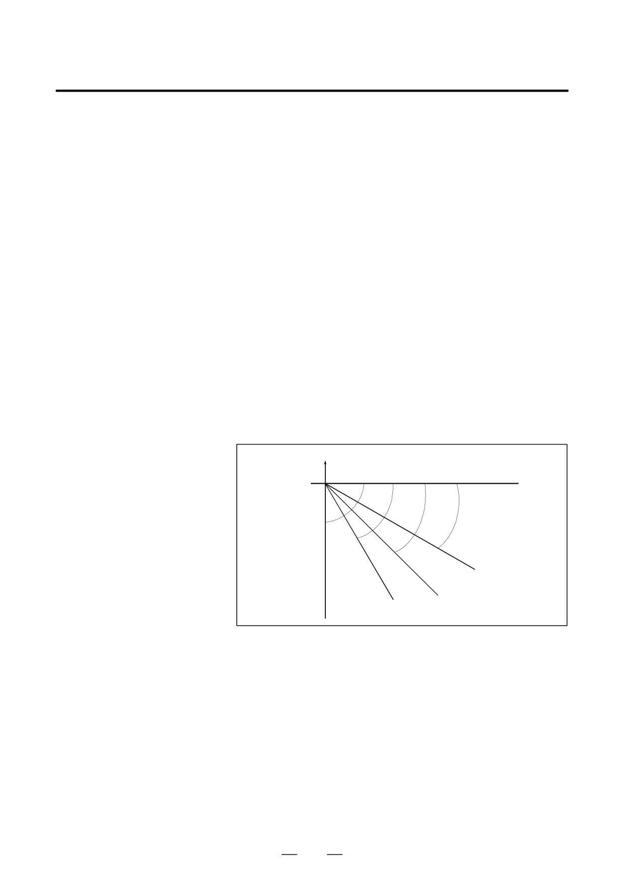
Usually, the cutting resistance is higher when machining is performed
with the bottom of the cutter, as shown in Fig. 22.1.2 (c) an when
machining is performed with the side of the cutter, as shown in Fig. 22.1.2
(d). Deceleration is, therefore, required. In AI High Precision Countour
Control, the tool travel direction on the Z-axis is used as a condition for
calculating the machining feedrate.
The descent angle during descent on the Z-axis (angle formed by the XY
plane and the tool center path) is as shown in Fig. 22.1.2 (d). The descent
angle is divided into four areas, and the override values for the individual
areas are set for the following parameters:
Parameter No. 8456 for area 2
Parameter No. 8457 for area 3
Parameter No. 8458 for area 4
For area 1, however, no parameter is available, and an override of 100%
is used at all times. The feedrate obtained according to other feedrate
control is multiplied by the override value of the area to which descent
angle belongs.
Area1
0°v q <30°
Area2
30°v q <45°
Area3
45°v q <60°
Area4
60°v q v90°
Z
XY plane
30°
Area1
90°
60°
Area4
45°
Area2
Area3
620

B-63534EN/02
PROGRAMMING
22. RISC PROCESSOR
CAUTION
1
The function for determining the feedrate with the cutting
feed is effective only when the tool is parallel with the
Z-axis. Thus, it may not be possible to apply this function,
depending on the structure of the machine used.
2
In the function for determining the feedrate with the cutting
feed, the travel direction on the Z-axis is determined with
the appropriate NC command. If, therefore, manual
intervention is performed on the Z-axis with manual
absolute on, or if a mirror image is applied on the Z-axis, the
direction on the Z-axis cannot be determined. When using
the function for determining the feedrate with the cutting
load, do not use these functions.
3
When performing three-dimensional coordinate conversion,
determine the descent angle on the Z-axis using the
converted coordinate system.
Ignoring F code
In a block in which automatic feedrate control is enabled, all feed
commands
commands (F commands) can be ignored by setting parameter NOF (bit
7 of No. 8451). The term feed commands, as used here, refer to the
following commands:
(1) Modal F commands before the block in which automatic feedrate
control is enabled
(2) F commands and modal F commands in the block in which automatic
feedrate control is enabled
When the F commands are ignored, it is assumed that the upper feedrate
limit specified for parameter No. 8465 is specified.
Note, however, that any issued F commands and modal F commands are
stored within the CNC.
Thus, in a block in which automatic feedrate control changes from the
enabled state to the disabled state, the modal values of the F commands
described in 1 and 2 described above are used as modal F commands,
instead of the modal values of the F commands calculated by automatic
feedrate control.
Override to a determined
The following gives the specifications of override to a feedrate
feedrate
determined by functions such as deceleration based on feedrate difference
in look-ahead acceleration/deceleration before interpolation and
deceleration based on acceleration rate in AI High Precision Countour
Control.
- When bit 3 (OVR) of parameter No. 8459 = 0
The conventional specifications apply.
Override is invalid for deceleration functions such as deceleration
based on feedrate difference and deceleration based on acceleration
rate.
- When bit 3 (OVR) of parameter No. 8459 = 1
Override is valid for deceleration functions such as deceleration based
on feedrate difference and deceleration based on acceleration rate.
621
22. RISC PROCESSOR
PROGRAMMING
B-63534EN/02
When bit 3 (OVR) of parameter No. 8459 is 1, the following feedrates can
be overridden:
- Feedrate decelerated by deceleration based on feedrate difference in
look-ahead acceleration/deceleration before interpolation
- Feedrate decelerated by deceleration based on acceleration rate in AI
High Precision Countour Control.
- Feedrate decelerated by deceleration based on acceleration rate in
circular interpolation
- Feedrate decelerated by acceleration clamp in involute interpolation
- Minimum feedrate for deceleration based on acceleration rate in AI
High Precision Countour Control and circular interpolation
- Maximum feedrate of AI High Precision Countour Control.
Even when the feedrate is overridden, the resulting feedrate does not
exceed the maximum cutting feedrate (parameter No. 1422 or No.1430
or No.1432).
Another example of
If the calculated feedrate exceeds either the upper limit (parameter No.
determining the feedrate
8465) for automatic feedrate control that is set for the appropriate
parameter or the feedrate specified with an F command, clamping is
performed with the smaller of the upper limit feedrate and the feedrate
specified with the F command.
If the feedrate calculated by the deceleration function based on the
acceleration is smaller than the lower feedrate limit for the deceleration
function based on the acceleration of AI High Precision Countour Control
set for parameter No. 19511, the lower feedrate limit is used for the
feedrate. If, however, the specified feedrate is smaller than the lower
feedrate limit, the specified feedrate is used.
Miscellaneous
In AI high precision contour control mode or in AI nano high precision
contour control mode, 3-dimensional coordinate conversion, coordinate
system rotation, scaling, and rotary table dynamic fixture offset can be
executed.
In the mode of each of the 3-dimensional coordinate conversion,
coordinate system rotation, scaling, and rotary table dynamic fixture
offset functions, AI high precision contour control mode or AI nano high
precision contour control mode can be turned on and off with the
appropriate parameter settings.
22.1.3
For the function which can be used and limitations in the AI High
Precision Contour Control mode or in the AI NANO High Precision
Restrictions
Contour Control mode, refer to the “Function List which can be used” and
“Restrictions”.
D Restriction-1
The following functions can be used but the state can not be changed in
the AI High Precision Contour Control mode or in the AI NANO High
Precision Contour Control mode.
S Inch/metric conversion (An alarm(P/S5000) is issued if the state is
changed by G20 or G21)
622
B-63534EN/02
PROGRAMMING
22. RISC PROCESSOR
S Mirror image (Do not change the state of the signal).
S F1 digit feed (Feedrate can not be changed by using the manual pulse
generator.)
D Restriction -2
The AI high Precision Contour Control mode or the AI Nano high
Precision Contour Control mode is automatically canceled once and the
buffering is inhibited if the following function is used in the AI high
Precision Contour Control mode or in the AI high Precision Contour
Control mode.
S MDI operation
S Workpiece coordinate system selection(G54 to G59)
S Programmable parameter input(G10)
S Miscellaneous function
S
2nd. Auxiliary function
S
1 block plural M commands
S Spindle speed function
S Tool function
S Fixed cycle(G73,G74,G76,G80 to G89,G98,G99)
(Set the parameter(No.5200#0=1) which an M code specifying the
rigid tapping mode is not used if the rigid tapping is used )
D Restriction -3
The following commands can not be used in the AI High Precision
Contour Control mode or AI NANO High Precision Contour Control
mode. The alarm is issued if the function was used.
S Custom macro
S Exponential interpolation
-G02.3,G03.3
S Dwell
-G04
S High Speed Cutting Function relation -G05
(G05P10000 and G05P0 are excluded)
S AI contour control
-G05.1Q1,G5.1Q0
S Hypothetical axis interpolation
-G07
S Advanced preview control
-G08
(Please use AI High Precision Contour Control)
S Polar coordinate interpolation
-G12.1,G13.1
S Polar coordinate command
-G15,G16
S Reference position return check
-G27
S Reference point return
-G28
S
2nd. Reference point return
-G30
S
3rd/4th reference point return
-G30
S Skip
-G31
S Thread cutting
-G33
S Automatic tool length measurement
-G37
S Normal direction control
-G40.1,G41.1,G42.1
S Cutter compensation B
-G41,G42,G39
(Cutter compensation C is available)
623
22.
RISC PROCESSOR
PROGRAMMING
B-63534EN/02
S
3-dimensional tool compensation
-G41
S Wheel wear compensation
-G41
S Tool offset
-G45,G46,G47,G48
S Local coordinate system
-G52
S Machine coordinate system
-G53
S Single direction positioning
-G60
S Automatic corner override
-G62
S Tapping mode
-G63
S Macro call
-G65,G66,G67
(SubProgram call is available)
S Figure copying
-G72.1,G72.2
S Simple electric gear box
-G80,G81
S Functions for hobbing machine
-G80,G81
S External operation function
-G81
S Chopping function
-G81.1
S Setting a workpiece coordinate system
-G92
S Workpiece coordinate system preset
-G92.1
S Feed per revolution
-G95
S Constant surface speed control
-G96,G97
S Infeed control
-G160,G161
D Restriction -4
The following functions can not be used in the AI High Precision Contour
Control mode or AI NANO High Precision Contour Control mode.
S Flexible synchronous control
S Sequence number comparison and stop
It is not possible to stop by the sequence number in the AI High
Precision Contour Control mode or in the AI Nano High
Precision Contour Control mode.
S Index table indexing
S Retrace function
Do not use retrace function in the program which uses the AI
High Precision Contour Control mode or the AI Nano High
Precision Contour Control.
S Rotary axis control
S Gentle curve normal direction control
S Tool life management
Tool life value is counted in the AI High Precision Contour
Control mode or in the AI Nano AI High Precision Contour
Control mode. However , do not use the command related to the
tool life management function.
S Macro executor (Execution macro)
S Manual handle interruption
624

B-63534EN/02
PROGRAMMING
22. RISC PROCESSOR
D Restriction -5
When the following function is used, a AI High Precision Contour
Control and the AI Nano High Precision Contour Control cannot be used.
S Angular axis control
S Arbitary angular axis control
D Restriction -6
The limitation may be attached about the combination of the NC
instructions occasionaly.
Refer the description of the each functions.
NOTE
1
If the permissible acceleration set for one axis is two or more times
greater than that set for another, the feedrate may decrease
temporarily at those corners where the travel direction changes
abruptly.
2
If the machine lock signal is turned on during travel in look-ahead
acceleration/deceleration before interpolation mode, the machine
enters the machine lock state after the end of deceleration.
3
If there is a block with no travel or a one-shot G code command
such as G04 in look-ahead acceleration/deceleration before
interpolation mode, deceleration is performed for a stop in the
preceding block.
4
If the dry run signal changes from “0” to “1” or from “1” to “0” during
travel on an axis, acceleration/deceleration is performed to achieve
the prescribed feedrate without deceleration to feedrate 0.
The function for deceleration with the feedrate difference at a
corner is effective even during dry run.
22.1.4
The Function List
which Can be Used
Item
Specifications
Note
Axis control
Controlled axes
3 axes
Controlled paths
1-path
Simultaneously controlled axes
2 axes
Controlled axis expansion
Up to 8 axes
Simultaneously controlled axis expan-
Up to 6 axes
sion
625

22. RISC PROCESSOR
PROGRAMMING
B-63534EN/02
Item
Specifications
Note
Axis control
Axis control by PMC
The axis which is used in the AI High
Precision Contour Control mode or in
the AI nano High Precision Contour
Control mode can not be used as the
control axis of the PMC Axis Control in
the AI High Precision Contour Control
mode or in the AI nano High Precision
Contour Control mode
Cs contour control
The nano interpolation and the Ad-
vanced preview feed-forward function
are canceled once when the command
for Cs axis in AI high precision contour
control mode or AI nano high precision
contour control mode
Axis name
3 basic axes: X,Y,Z; Additional axes:
U,V,W,A,B, or C
Twin table control
Synchronized operation/individual op-
eration/a normal drive cannot be
changed in the AI high precision con-
tour control mode or in the AI nano
high precision contour control mode
Please include all the twin table control
axes to the maximum control axis
number (parameter No.7510) of RISC.
Simple synchronous control
Synchronized operation/individual op-
eration/a normal drive cannot be
changed in the AI high precision con-
tour control mode or in the AI nano
high precision contour control mode
Please include all the simple synchro-
nous control axes to the maximum
control axis number (parameter
No.7510) of RISC.
Least input increment
0.001mm,0.001deg,0.0001inch
Incremental System 1/10
0.0001mm,0.0001deg,0.00001inch
Inch/metric conversion
Inch mode / metric mode cannot be
changed in the AI high precision con-
tour control mode or in the AI nano
high precision contour control mode.
Interlock
All axes/each axis
Machine lock
All axes/each axis
Emergency stop
Stored stroke check 1
The stroke limit cannot be set by the
stroke limit external setting signal in
the AI high precision contour control
mode or in the AI nano high precision
contour control mode. Overrun on the
OT limit does not occur in the AI high
precision contour control mode or in
the AI nano high precision contour
control mode.
626

B-63534EN/02
PROGRAMMING
22. RISC PROCESSOR
Item
Specifications
Note
Axis control
Stored stroke check 2
The AI high precision contour control
mode or the AI nano high precision
contour control mode is automatically
canceled once and the buffering is in-
hibited if G22 or G23 is used in the AI
high Precision Contour Control mode
or in the AI high Precision Contour
Control mode,
Mirror image
Do not change the state of the signal in
the AI High Precision Contour Control
mode or AI nano High Precision Con-
tour Control mode.
Backlash compensation for each rapid
traverse and cutting feed
Operation
Automatic operation
MDI operation
The AI high precision contour control
mode or the AI nano high precision
contour control mode is automatically
canceled once and the buffering is in-
hibited if the MDI operation is used in
the AI high Precision Contour Control
mode or in the AI high Precision Con-
tour Control mode. At this time,
G05P10000 or G05P0 can not be used
by the MDI operation.
Cycle start/Feed hold
Program stop/Program end
Reset
Program restart
Program restart function can not be
used in NURBS interpolation, smooth
interpolation, and cylindrical interpola-
tion.
Dry run
Single block
Interpolation functions
Positioning
G00
The AI high precision contour control
function or AI nano high precision con-
tour control functions except the ad-
vanced preview feed-forward function,
multi buffer function , and the nano in-
terpolation become invalid.
Exact stop mode
G61
Exact stop
G09
Cutting mode
G64
627

22. RISC PROCESSOR
PROGRAMMING
B-63534EN/02
Item
Specifications
Note
Interpolation functions
Linear interpolation
G01
Circular interpolation
G02,G03
Helical interpolation
(Circular interpolation) + (Linear inter-
polation for up to 2 axes)
Helical interpolation B
(Circular interpolation) + (Linear inter-
polation for up to 4 axes)
Involute interpolation
G02.2,G03.2
3-dimensional circular interpolation
G02.4,G03.4
The position is checked at the end
point of the block which cancel 3 di-
mensional circular interpolation or at
the end point of the previous block of
the 3 dimensional circular interpolation
if 3 dimensional circular interpolation is
used except in AI high precision con-
tour control mode or AI nano high pre-
cision contour control mode.
Smooth interpolation
G05.1
This function can be used in AI high
precision contour control mode or AI
nano high precision contour control
mode.
NURBS interpolation
G06.2
This function can be used in AI high
precision contour control mode or AI
nano high precision contour control
mode.
Cylindrical interpolation
G07.1
This function can be used in AI high
precision contour control mode or AI
nano high precision contour control
mode.
Cylindrical interpolation cutting point
G07.1
This function can be used in AI high
control
precision contour control mode or AI
nano high precision contour control
mode.
Conical / spiral interpolation
G02,G03
Feed functions
Feed per minute
G94
Cutting feedrate clamp
Linear acceleration/deceleration of cut-
ting feed after interpolation
Bell-type acceleration/deceleration of
cutting feed after interpolation
Feedrate override
0 to 254%
(1% step)
2nd. Feedrate override
0 to 254%
(1% step)
628

B-63534EN/02
PROGRAMMING
22. RISC PROCESSOR
Item
Specifications
Note
Feed functions
F1 digit feed
Using the manual pulse generator can
not change Feedrate.
Inverse time feed
G93
External deceleration
External deceleration
Look ahead liner-type acceleration/
deceleration before interpolation.
Look ahead Bell-type acceleration/
Acceleration change time constant
deceleration before interpolation
type
Program input
Tape code
Automatic recognition of EIA/ISO
Program format
Word address format
Control in/out
Optional block skip
Absolute/incremental programming
G90/G91
Input unit 10 time multiply
Plane selection
G17,G18,G19
Rotary axis roll over
Workpiece coordinate system selec-
G54 to G59
The AI high precision contour control
tion
mode or the AI nano high precision
contour control mode is automatically
canceled once and the buffering is in-
hibited if this function is used in the AI
high Precision Contour Control mode
or in the AI high Precision Contour
Control mode.
Addition of workpiece coordinate sys-
48 sets / 300 sets
The AI high precision contour control
tem pair
mode or the AI nano high precision
contour control mode is automatically
canceled once and the buffering is in-
hibited if this function is used in the AI
high Precision Contour Control mode
or in the AI high Precision Contour
Control mode.
Manual absolute ON/OFF
Programmable parameter input
G10
The AI high precision contour control
mode or the AI nano high precision
contour control mode is automatically
canceled once and the buffering is in-
hibited if this function is used in the AI
high Precision Contour Control mode
or in the AI high Precision Contour
Control mode.
629

22. RISC PROCESSOR
PROGRAMMING
B-63534EN/02
Item
Specifications
Note
Program input
External memory and sub program
M198
calling function
Subprogram call
M98
Circular interpolation by R program-
ming
Scaling
G50,G51
The mode of AI high precision contour
control or of AI nano high precision
contour control is permitted to change
ON and OFF in scaling mode by set-
ting the parameter.
The alarm (P/S5012) occurs if the
mode of AI high precision contour con-
trol or of AI nano high precision con-
tour control is changed in scaling mode
(G51) when the parameter is not set.
The scaling mirror image by a negative
magnification can not be done.
Coordinate system rotation
G68,G69
The mode of AI high precision contour
control or of AI nano high precision
contour control is permitted to change
ON and OFF in coordinate system
rotation mode by setting the parameter.
The alarm (P/S5012) occurs if the
mode of AI high precision contour con-
trol or of AI nano high precision con-
tour control is changed in coordinate
system rotation mode (G51) when the
parameter is not set.
3-dimensional coordinate system con-
G68,G69
The mode of AI high precision contour
version
control or of AI nano high precision
contour control is permitted to change
ON and OFF in 3-dimensional coordi-
nate system conversion mode by set-
ting the parameter. The alarm
(P/S5012) occurs if the mode of AI
high precision contour control or of AI
nano high precision contour control is
changed in 3-dimensional coordinate
system conversion when the parame-
ter is not set.
Miscellaneous/spindle functions
Miscellaneous function
The AI high precision contour control
mode or the AI nano high precision
contour control mode is automatically
canceled once and the buffering is in-
hibited if this function is used in the AI
high Precision Contour Control mode
or in the AI high Precision Contour
Control mode.
630

B-63534EN/02
PROGRAMMING
22. RISC PROCESSOR
Item
Specifications
Note
Miscellaneous/spindle functions
2nd. Auxiliary function
The AI high precision contour control
mode or the AI nano high precision
contour control mode is automatically
canceled once and the buffering is in-
hibited if this function is used in the AI
high Precision Contour Control mode
or in the AI high Precision Contour
Control mode.
1 block plural M commands
The AI high precision contour control
mode or the AI nano high precision
contour control mode is automatically
canceled once and the buffering is in-
hibited if this function is used in the AI
high Precision Contour Control mode
or in the AI high Precision Contour
Control mode.
It is possible to command up to 3.
Spindle speed function
The AI high precision contour control
mode or the AI nano high precision
contour control mode is automatically
canceled once and the buffering is in-
hibited if this function is used in the AI
high Precision Contour Control mode
or in the AI high Precision Contour
Control mode.
Tool functions
Tool function (T8-digit)
The AI high precision contour control
mode or the AI nano high precision
contour control mode is automatically
canceled once and the buffering is in-
hibited if this function is used in the AI
high Precision Contour Control mode
or in the AI high Precision Contour
Control mode.
Tool retract & recover
G10.6
Issue the G10.6 command prior to the
G05 P10000 command that causes
the system to enter AI high precision
contour control or AI nano contour con-
trol mode. The alarm (P/S 5000) oc-
curs if it is issued in this mode.
Tool length compensation
G43
Cutter compensation C
G38,G39,G40,G41,G42
The buffering is inhibited when the
command which automatically cancel
AI high precision contour control mode
or AI nano high precision contour con-
trol mode is used.
So the tool offset vector is held.
631

22. RISC PROCESSOR
PROGRAMMING
B-63534EN/02
Item
Specifications
Note
Tool functions
3-dimensional tool compensation
G41.2,G42.2
The command which automatically
G41.3
cancel AI high precision contour con-
trol mode or AI nano high precision
contour control mode can not be used.
However M,S,T and B command can
be used without the command that
move some axes. In this case, the off-
set vector is held because the buffer-
ing is inhibited.
Tool axis direction tool length com-
G43.1
The command which automatically
pensation
cancel AI high precision contour con-
trol mode or AI nano high precision
contour control mode can not be used.
However M,S,T and B command can
be used without the command that
move some axes. In this case, the off-
set vector is held because the buffer-
ing is inhibited.
Tool center point control
G43.4,G43.5
The command which automatically
cancel AI high precision contour con-
trol mode or AI nano high precision
contour control mode can not be used.
However M,S,T and B command can
be used without the command that
move some axes. In this case, the off-
set vector is held because the buffer-
ing is inhibited.
Rotary table dynamic fixture offset
G54.2
The mode of AI high precision contour
control or of AI nano high precision
contour control is permitted to change
ON and OFF in rotary table dynamic
fixture offset mode by setting the pa-
rameter. The alarm (P/S5012) occurs if
the mode of AI high precision contour
control or of AI nano high precision
contour control is changed in rotary
table dynamic fixture offset mode when
the parameter is not set.
632
B-63534EN/02
PROGRAMMING
22. RISC PROCESSOR
22.2
CYLINDRICAL
INTERPOLATION
CUTTING POINT
CONTROL (G07.1)
General
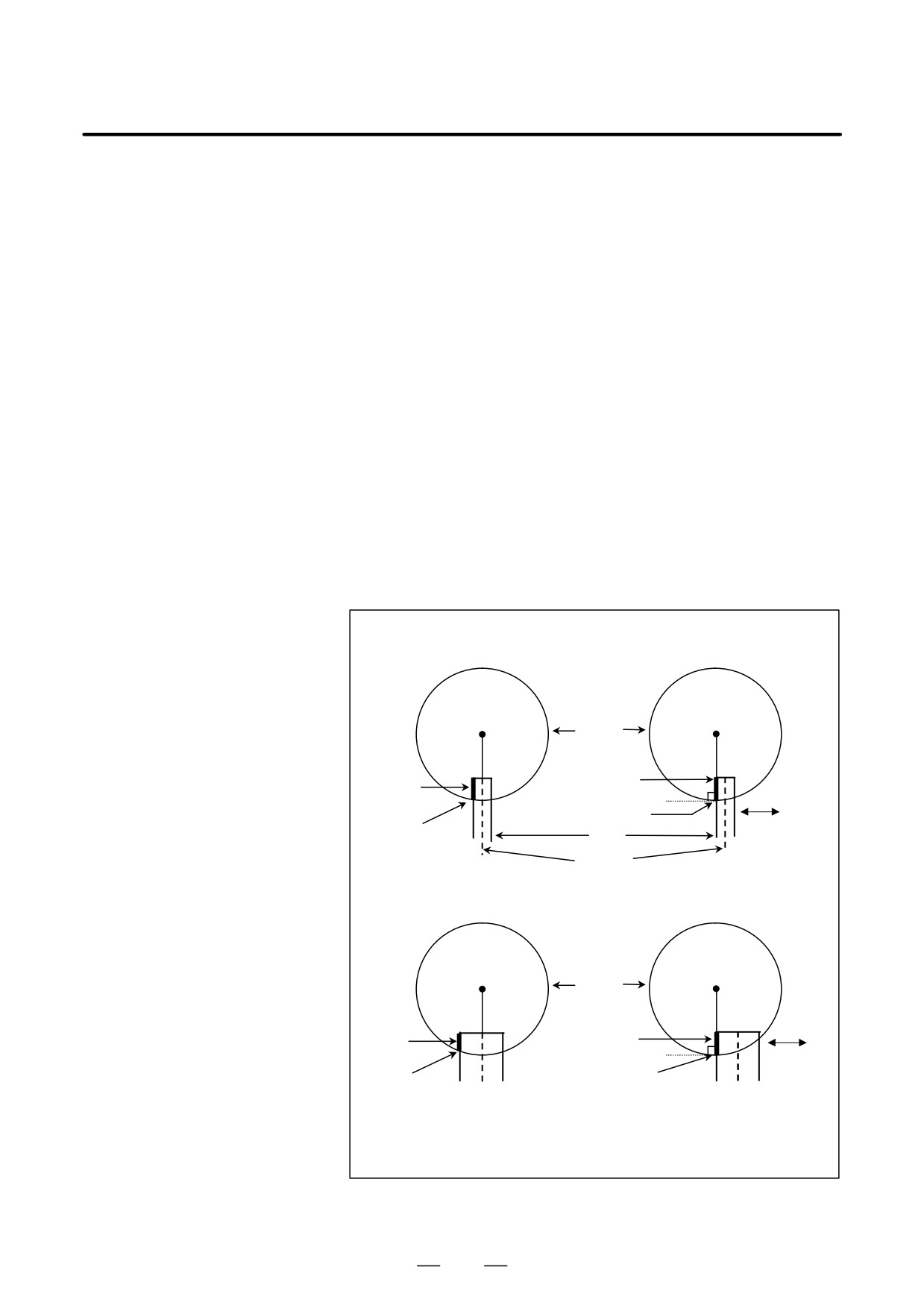
The conventional cylindrical interpolation function controls the tool
center so that the tool axis always moves along a specified path on the
cylindrical surface, towards the rotation axis (cylindrical axis) of the
workpiece. On the other hand, this function controls the tool so that the
tangents to the tool and a contour figure cutting surface always pass
through the rotation center of a workpiece
As shown in Fig.22.2 (a), control is exercised along the offset axis
(Y-axis) direction that is perpendicular to the tool, tool center axis, and
workpiece rotation center axis. Therefore, contour figure on the cutting
side can be assumed to be the same anytime without depending on the
amount of the cutter compensation.
This function can be used in AI high precision contour control mode or
in AI NANO high precision contour control mode.
Conventional cylindrical
Cylindrical interpolation based
interpolation
on this function
Rotation
Workpiece
Rotation
Cutting side
Cutting
side
Command Position
Y-axis
Command
Tool
Position
Tool
center
In the case of the amount of the
cutter compensation is large;
Workpiece
Rotation
Rotation
Cutting
Cutting
side
side
Y-axis
Command
Command
Position
Position
Shape on the cutting side changes de-
Shape on the cutting side does not de-
pending on the amount of cutter com-
pend on the amount of cutter com-
pensation because the tool path is
pensation by moving the Y axis.
compensated by moving the rotation
The cutting side is always vertical to
axis.
the cylinder.
Fig. 22.2 (a) Comparison with Conventional Interpolation
633
22. RISC PROCESSOR
PROGRAMMING
B-63534EN/02
Format
G05 P10000 ; Sets AI High precision contour control mode.
:
G07.1 IPr ;
Sets cylindrical interpolation mode.
:
..G41(G42)..
Sets cutter compensation mode.
:
..G40..
Clear cutter compensation mode.
:
G07.1 IP0 ;
Clears cylindrical interpolation mode.
G05 P0 ;
Clears AI high precison contour control mode.
IP
: One rotation axis address
r
: Cylinder radius of rotation axis
Specify each of G07.1 IPr; and G07.1 IP0; singly in a block.
Explanations
D Cutting point
compensation
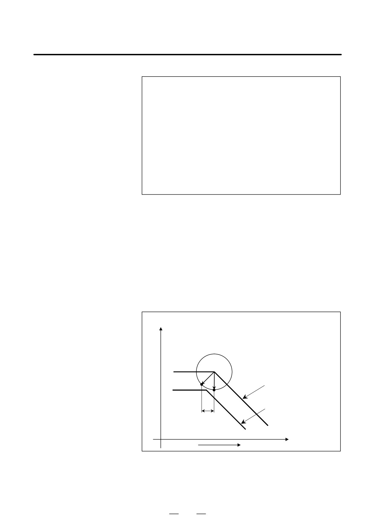
(1) Cutting point compensation between blocks
As shown in Fig. 22.2 (b), cutting point compensation is achieved by
moving between blocks N1 and N2.
1) Let C1 and C2 be the heads of the vectors normal to N1 and N2
from S1, which is the intersection of the tool center paths of blocks
N1 and N2
2) After the tool moves to S1 according to the command of N1, the
tool moves through V on the C-axis as a result of cutting point
p
compensation, then through -V
r along the Y-axis.
180
Z-axis
V
: C-axis component of C1 - C2
C1 : Cutting surface of block N1
C2 : Cutting surface of block N2
S1
C2
Cutting surface
of block N2
C1
N1
Programmed path
N2
V
C-axis on the
Y-axis
cylindrical surface
Fig. 22.2 (b) Cutting Point Compensation between Blocks
(2)
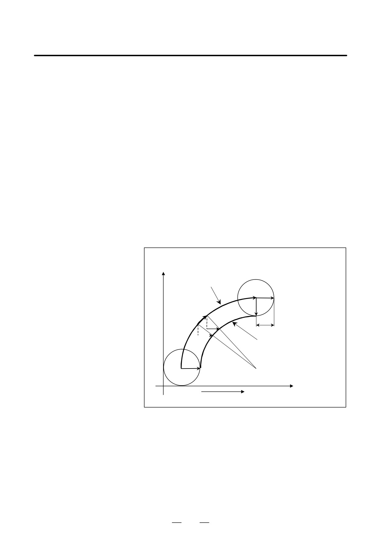
Cutting point compensation in a circular command block
As shown in
Fig. 22.2 (c), the movement required for cutting point compensation
is made simultaneously with circular interpolation in block N1.
634
B-63534EN/02
PROGRAMMING
22. RISC PROCESSOR
1) Let C0 be the head of the vector normal to N1 from S0, which is
the tool center position at the start point of circular block N1. Let
C1 be the head of the similar vector at the end point.
2) As the tool moves from S0 to S1, a superimposed movement is
made by the C-axis component of (C1 - C2) (V in the figure) on
the C-axis, and a superimposed movement is made by
p
-V
r along the Y-axis. along the Y-axis. That is, the
180
following expressions are valid. As movement is made through
L as shown in
Fig. 22.2 (c), the superimposed movements are made on the C-axis
and Y-axis as follows:
DC + DV
p
DY + *
(DV)r
180
nV
: Cutting point compensation value (nV2 - nV1) for
movement of nL
nV1 : C-axis component of the vector normal to N1 from the
tool center of the start point of nL
nV2 : C-axis component of the vector normal to N1 from the
tool center of the end point of nL
R
: Arc radius
V
: C-axis component of C1 - C0
C0 : Cutting surface at the start
Z-axis
point of block N1
C1 : Cutting surface at the end point
of block N1
Tool center path
S1
C0
C1
nL
V
nV2
nV1
R
Programmed path
N1
C0
S0
O
C-axis on the
Y-axis
cylindrical surface
Fig. 22.2 (c) Cutting Point Compensation in a Circular Command Block
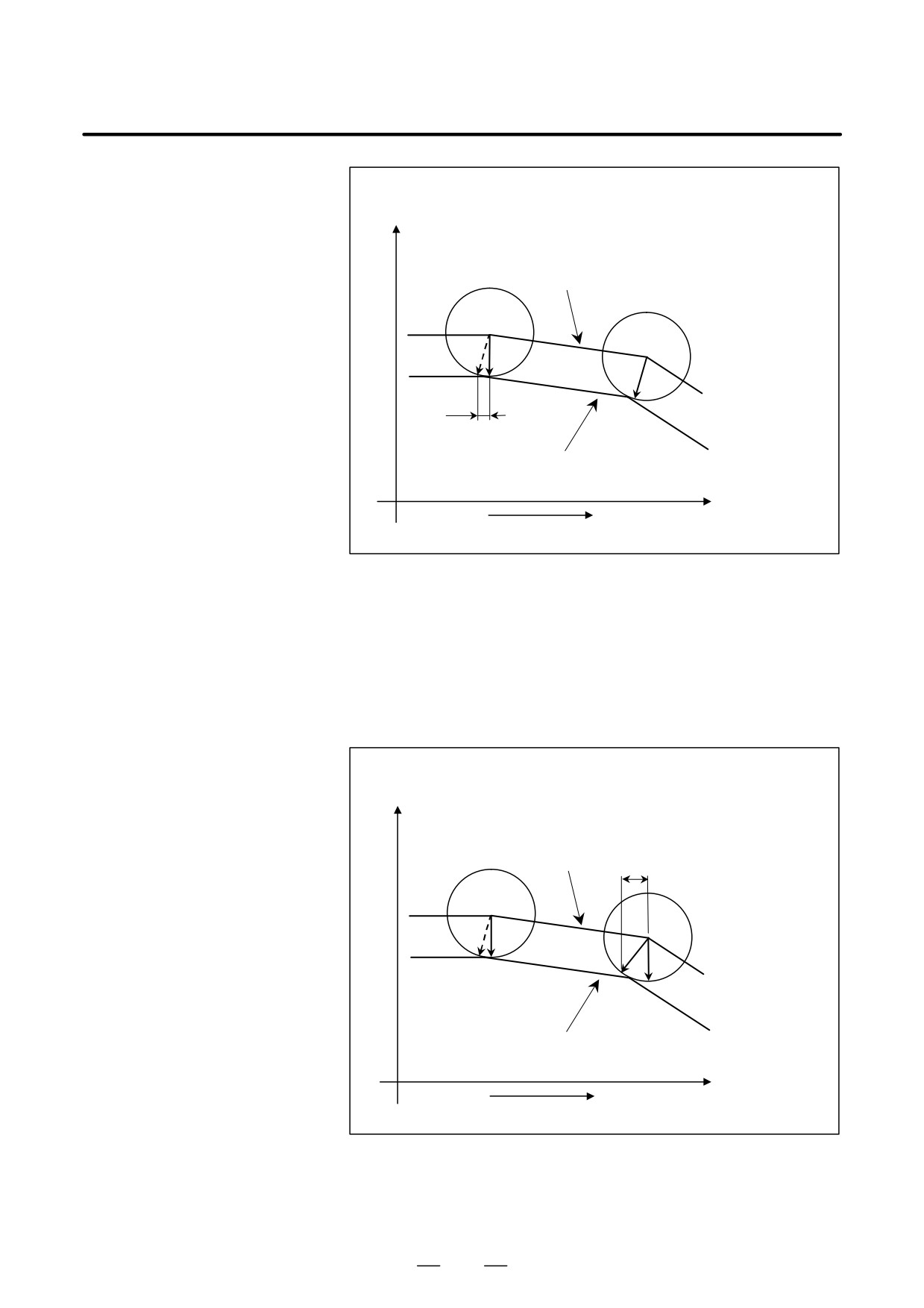
(3) When cutting point compensation is not applied between blocks
When, as shown in Fig. 22.2 (d) and Fig. 22.2 (e), the cutting point
compensation value (V in the figures) is less than the value set in
parameter No. 6112, one of the operations below is performed. (The
operation that is performed depends on the setting of bit 6 (CYS) of
parameter No. 6004.
1) When bit 6 (CYS) of parameter No. 6004 is set to 1
Cutting point compensation is not applied between blocks N1 and
N2, but is applied when block N2 is executed.
635
22. RISC PROCESSOR
PROGRAMMING
B-63534EN/02
V
: C-axis component of C2 - C1
Z-axis
C1 : Cutting surface of block N1
C2 : Cutting surface after the end of
block N1
Tool center path
S1
S2
C2
C1
N1
C2
N2
V
N3
Programmed path
C-axis on the
Y-axis
cylindrical surface
Fig. 22.2 (d) When Bit 6 (CYS) of Parameter No. 6004 Is Set to 1
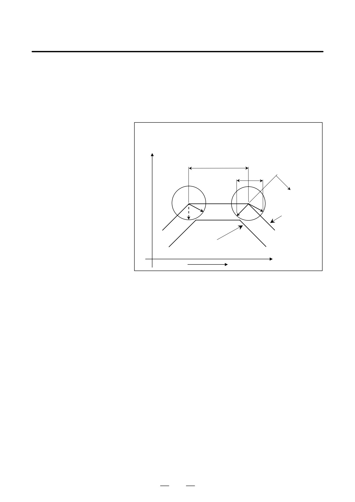
2) When bit 6 (CYS) of parameter No. 6004 is set to 0
Cutting point compensation is not performed between blocks N1
and N2. Whether to apply cutting point compensation between
block N2 and N3 is determined by taking the cutting point
compensation value between blocks N2 and N3 (V1 in the figure)
into consideration.
V
: C-axis component of C2 - C1
C1 : Cutting surface of blocks N1
Z-axis
and N2
C2 : Cutting surface at the end of
block N3
Tool center path
V
S1
S2
C1
C2
C1
N1
N2
N3
Programmed path
C-axis on the
Y-axis
cylindrical surface
Fig. 22.2 (e) When Bit 6 (CYS) of Parameter No. 6004 Is 0
636
B-63534EN/02
PROGRAMMING
22. RISC PROCESSOR
3) When the amount of travel (L1) of block N2 is less than the value
set in parameter No. 6113, as shown in Fig. 22.2 (f), cutting point
compensation is not applied between blocks N1 and N2. Instead,
block N2 is executed with the cutting point compensation of the
previous block. When the amount of travel (L2) of block N3 is
greater than the value set in parameter No. 6113, cutting point
compensation is applied between blocks N2 and N3.
V
: C-axis component of C2 - C1
C1 : Cutting surface of blocks N1 and N2
Z-axis
C2 : Cutting surface at the end of block N3
L1
V
L2
C1
C2
C1
Tool center path
N2
N1
N3
Programmed path
C-axis on the
Y-axis
cylindrical surface
Fig. 22.2 (f) When the Amount of Travel (L1) of Block N2 Is Less Than the
Parameter Value
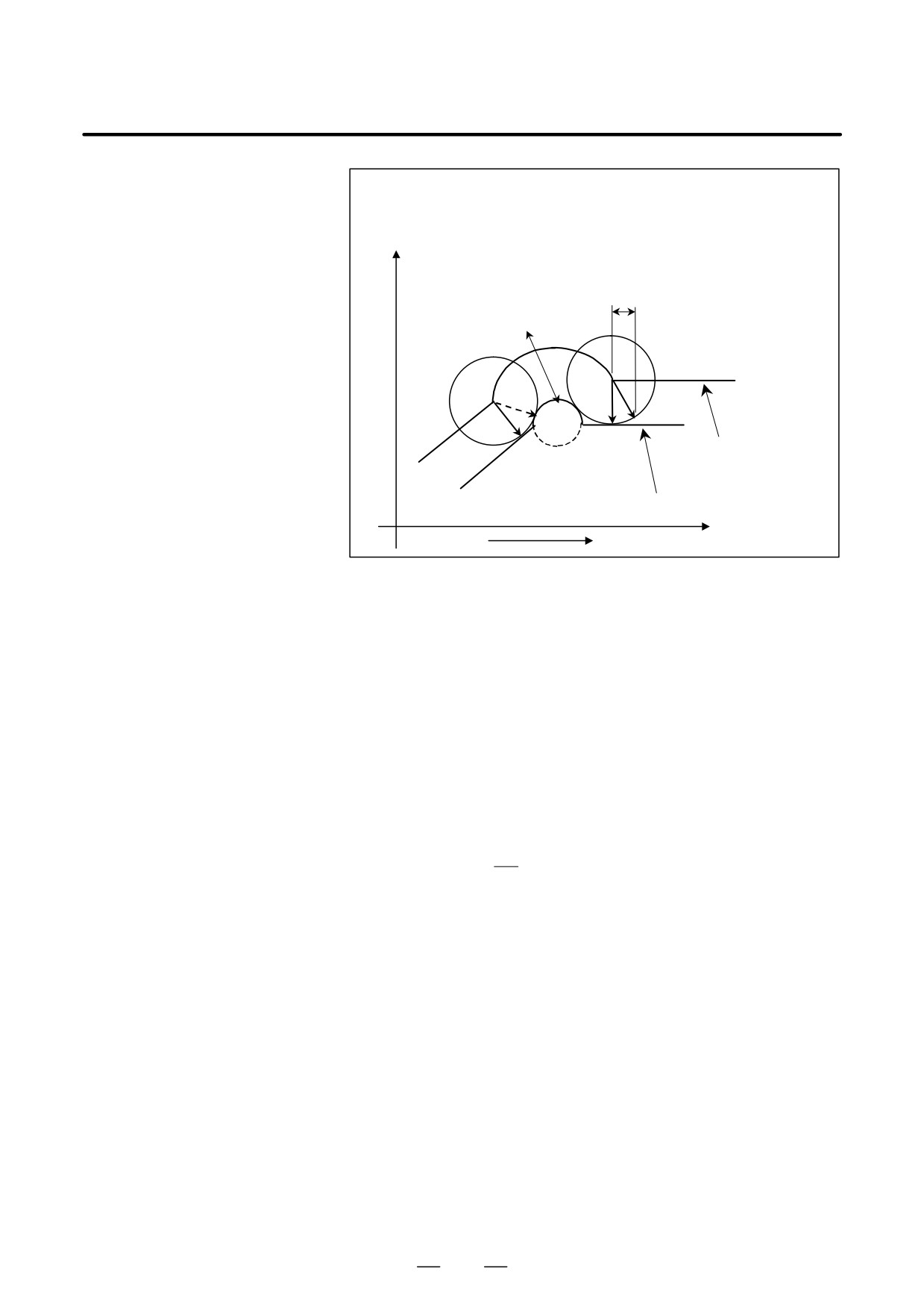
4) When, as shown in Fig. 22.2 (g), the diameter of an arc (R in the
figure) is less than the value set in parameter No. 6113, cutting
point compensation is not applied simultaneously with circular
interpolation
637
22. RISC PROCESSOR
PROGRAMMING
B-63534EN/02
V
: Cutting point compensation between
blocks N2 and N3
C1 : Cutting surface of blocks N1 and N2
Z-axis
C2 : Cutting surface of block N3
L1
V
R
S2
N2
S1
C1
C2
N3
C1
Tool center path
N1
Programmed path
C-axis on the
Y-axis
cylindrical surface
Fig. 22.2 (g) When the Diameter of an Arc Is Less Than the Parameter
Value
D Feedrate during cutting
point compensation
(1)
The tool moves at a specified feedrate while cutting point
compensation is being applied between blocks.
(2)
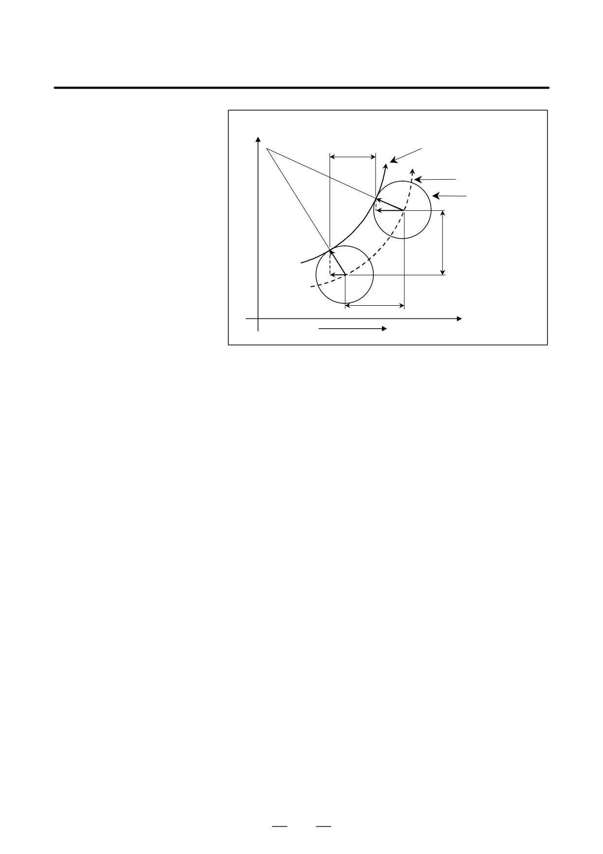
The actual speed indication and feedrate during circular interpolation
are as described below.
Actual speed indication
The speed component of each axis after cutting point compensation
at a point in time during circular interpolation is as follows:
Fz’=Fz
- - - Speed component of linear axis
Fc’=Fc+(Vce-Vcs)
- - - Speed component of rotation axis
p
r
Fy’=-(Vce-Vcs)
– - - Speed component of offset axis
180
Fz : Speed component of a cylindrical interpolation linear axis
before cutting point compensation
Fc : Speed component of cylindrical interpolation rotation axis
before cutting point compensation
Vcs: Rotation axis component of a tool contact point vector (Vs
in the figure) at the start point at a point in time
Vce: Rotation axis component of tool contact point vector (Ve in
the figure) at the end point at a point in time
r :
Radius of the cylinder of a rotation axis
Accordingly, the actual speed indication during circular
interpolation is greater than the specified value when |Fc’| >
|Fc|(inner offset of the arc). Conversely, the actual speed
indication during circular interpolation is less than the
specified value when |Fc’| < |Fc|(outer offset of the arc).
638
B-63534EN/02
PROGRAMMING
22. RISC PROCESSOR
Z-axis
Fc’
Programmed path
Tool center path
Ve
Tool
Vce
Fz = Fz’
Vs
Vcs
Fc
C-axis
Y-axis
Fig. 22.2 (h) Actual Speed Indication during Circular Interpolation
D Usable G codes
(1) In any of the following G code modes, cylindrical interpolation
cutting point compensation can be specified:
G17,G18,G19 : Plane selection
G22
: Stored stroke check function on
G64
: Cutting mode
G90,G91
: Absolute command programming, incremental
command programming
G94
: Feed per minute
(2) Any of the following G codes can be specified in cylindrical
interpolation cutting point compensation mode:
G01,G02 ,G03 : Linear interpolation, circular interpolation
G04
: Dwell
G40,G41,G42 : Cutter compensation
G40.1-G42.
: Normal direction control
G64
: Cutting mode
G65-G67
: Macro call
G90,G91
: Absolute command programming, incremental
command programming
D Parameter
Set to use this function as parameter CYA (No.19530#5)=1.
Limitation
D Overcutting during inner
Theoretically, when the inner area of a corner is cut using linear
corner cutting
interpolation as shown in Fig. 22.2 (i), this function slightly overcuts the
inner walls of the corner. This overcutting can be avoided by specifying
a value of R that is slightly greater than the radius of the tool at the corner.
639