FANUC Series 16i/160i/160is-MB, Series 18i/180i/180is-MB5, Series 18i/180i/180is-MB. Operator's Manual - page 4
4. INTERPOLATION FUNCTIONS
PROGRAMMING
B-63534EN/02
Limitations
D Number of involute curve
Both the start point and end point must be within 100 turns from the point
turns
where the involute curve starts. An involute curve can be specified to
make one or more turns in a single block.
If the specified start point or end point is beyond 100 turns from the point
where the involute curve starts, P/S alarm No. 242 is issued.
D Unspecifiable functions
In involute interpolation mode, chamfer corner R (with an arbitrary
angle), helical cutting, or axis-by-axis scaling functions cannot be
specified.
D Modes that do not allow
Involute interpolation cannot be used in the following modes:
involute interpolation
G41.1 (G151) : Normal direction control left side on
specification
G42.1 (G152) : Normal direction control right side on
G07.1 (G107) : Cylindrical interpolation
G12.1
: Polar coordinate interpolation mode
G16 : Polar coordinates command
G72.1
: Drawing copy
D Cutting accuracy
The curvature of an involute curve varies rather sharply near the base
circle. In such locations, a larger load is applied to the cutter when the
programmed feedrate is used for cutting; in this case, the surface produced
may be somewhat uneven
70
B-63534EN/02
PROGRAMMING
4. INTERPOLATION FUNCTIONS
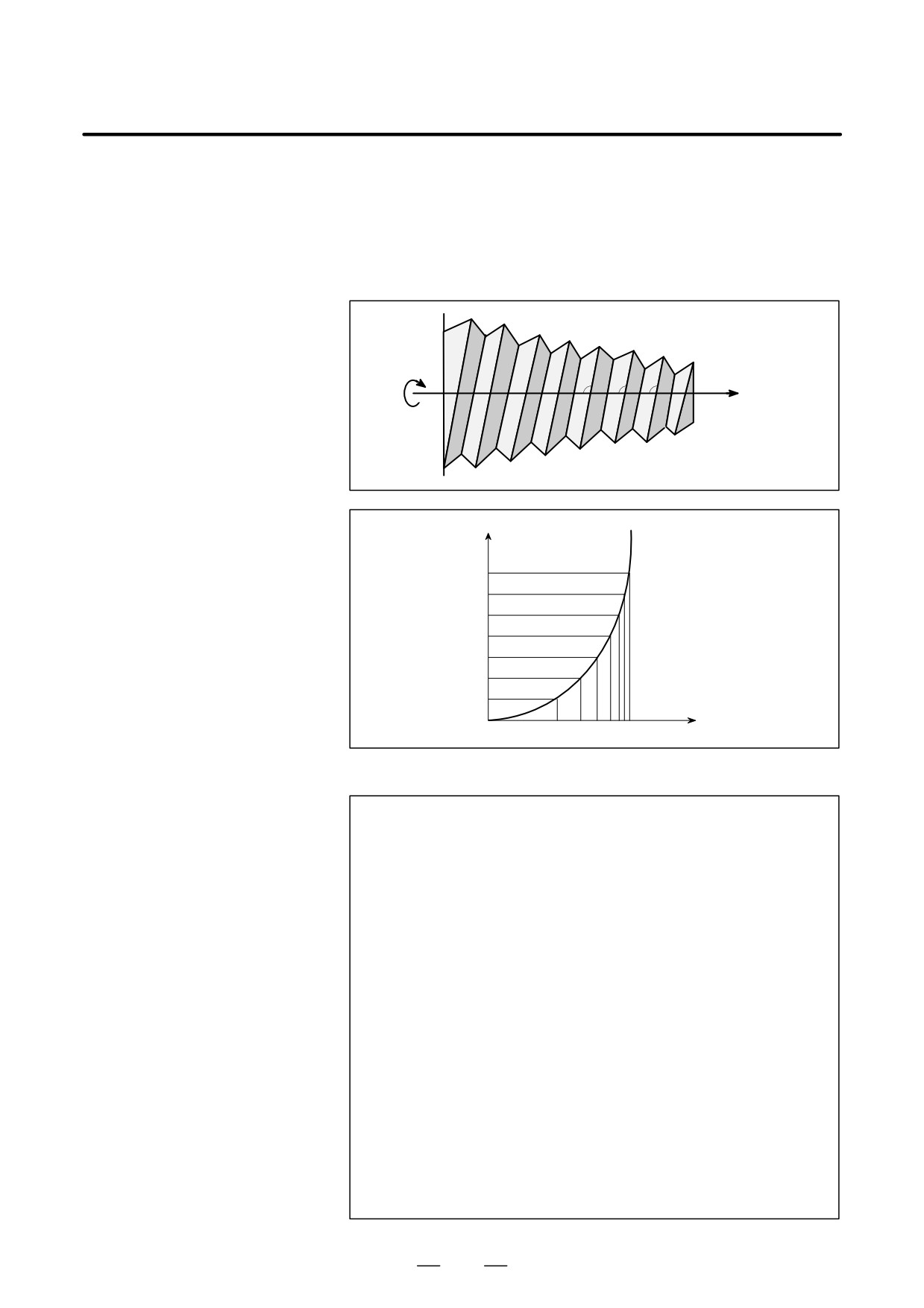
Exponential interpolation exponentially changes the rotation of a
4.11
workpiece with respect to movement on the rotary axis. Furthermore,
EXPONENTIAL
exponential interpolation performs linear interpolation with respect to
INTERPOLATION
another axis. This enables tapered groove machining with a constant
helix angle (constant helix taper machining). This function is best suited
(G02.3, G03.3)
for grooving and grinding tools such as end mills.
Z
β3
β2
β1
X
A
Helix angle
β1 = β2 = β3
X (Linear axis)
nX
A (Rotary axis)
nA
Format
positive rotation (ω=0)
G02. 3 X__ Y__ Z__ I__ J__ K__ R__ F__ Q__ ;
Negative rotation (ω=1)
G03. 3 X__ Y__ Z__ I__ J__ K__ R__ F__ Q__ ;
X__ ; Specifies an end point with an absolute or incremental value.
Y__ ; Specifies an end point with an absolute or incremental value.
Z__ ; Specifies an end point with an absolute or incremental value.
I__ ; Specifies angl I (from "1to "89 deg in units of 0.001deg ).
J__ ; Specifies angle J (from "1 to "89 degin units of 0.001deg).
K__ ; Specifies the amount to divide the linear axis for exponential
interpolation (span value). Specify a positive value.
When no value is specified, the value specified in parameter
(No. 5643) is used.
R__; Specifies constant R for exponential interpolation.
F__ ; Specifies the initial feedrate.
Specified in the same way as an ordinary F code. Specify a
composite feedrate including a feedrate on the rotary axis.
Q__
; Specifies the feedrate at the end point.
The same unit used for F is used. The CNC internally performs
interpolation between the initial feedrate (F) and final feedrate
(Q), depending on the travel distance on the linear axis.
71
4. INTERPOLATION FUNCTIONS
PROGRAMMING
B-63534EN/02
Explanations
D Exponential relational
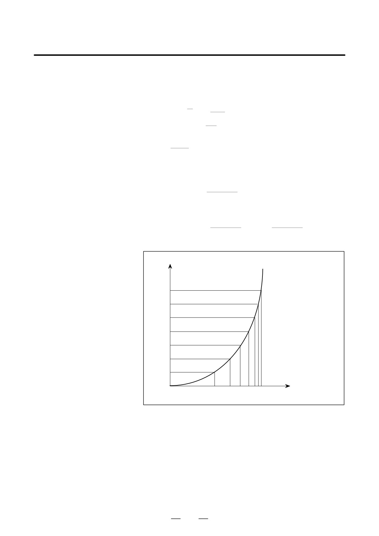
Exponential relational expressions for a linear axis and rotary axis are
expressions
defined as follows:
θ
1
k
X(θ)=R
(e
-1)
⋅⋅⋅⋅⋅⋅⋅⋅⋅⋅
Movement on the linear axis (1)
tan (I)
θ
A(q)=(-1)w
360
⋅⋅⋅⋅⋅⋅⋅⋅⋅⋅
Movement on the linear axis (2)
2π
Where,
tan (J)
K =
tan (I)
ω=0/1
⋅⋅⋅⋅⋅⋅⋅⋅⋅⋅⋅⋅⋅⋅⋅⋅⋅⋅⋅
Rotation direction
R, I, and J are constants, and θ represents an angle (radian)
The following is obtained from Expression (1)
X tan (I)
q(X)=K ln(
+1)
R
When there is movement from X1 to X2 on the linear axis, the
amount of movement on the rotary axis is determined by :
X2 tan (I)
X1 tan (I)
Dq= K
{ ln (
+1) - ln (
+1)}
R
R
Specify Expressions (1) and (2) in the format described earlier.
X (linear axis)
nX
A (rotary axis)
nA
Limitations
D Cases where linear
Even when the G02.3 or G03.3 mode is set, linear interpolation is
interpolation is
performed in the following cases:
performed
S When the linear axis specified in parameter( No. 5641) is not specified,
or the amount of movement on the linear axis is 0
S When the rotary axis specified in parameter (No. 5642) is specified
S When the amount for dividing the linear axis (span value) is 0
D Tool length
Neither tool length compensation nor cutter compensation can be used in
compensation / cutter
the G02.3 and G03.3 modes.
compensation
72
B-63534EN/02
PROGRAMMING
4. INTERPOLATION FUNCTIONS
CAUTION
The amount for dividing the linear axis for exponential
interpolation (span value) affects figure precision. However,
if an excessively small value is set, the machine may stop
during interpolation. Try to specify an optimal span value
depending on the machine being used.
Examples
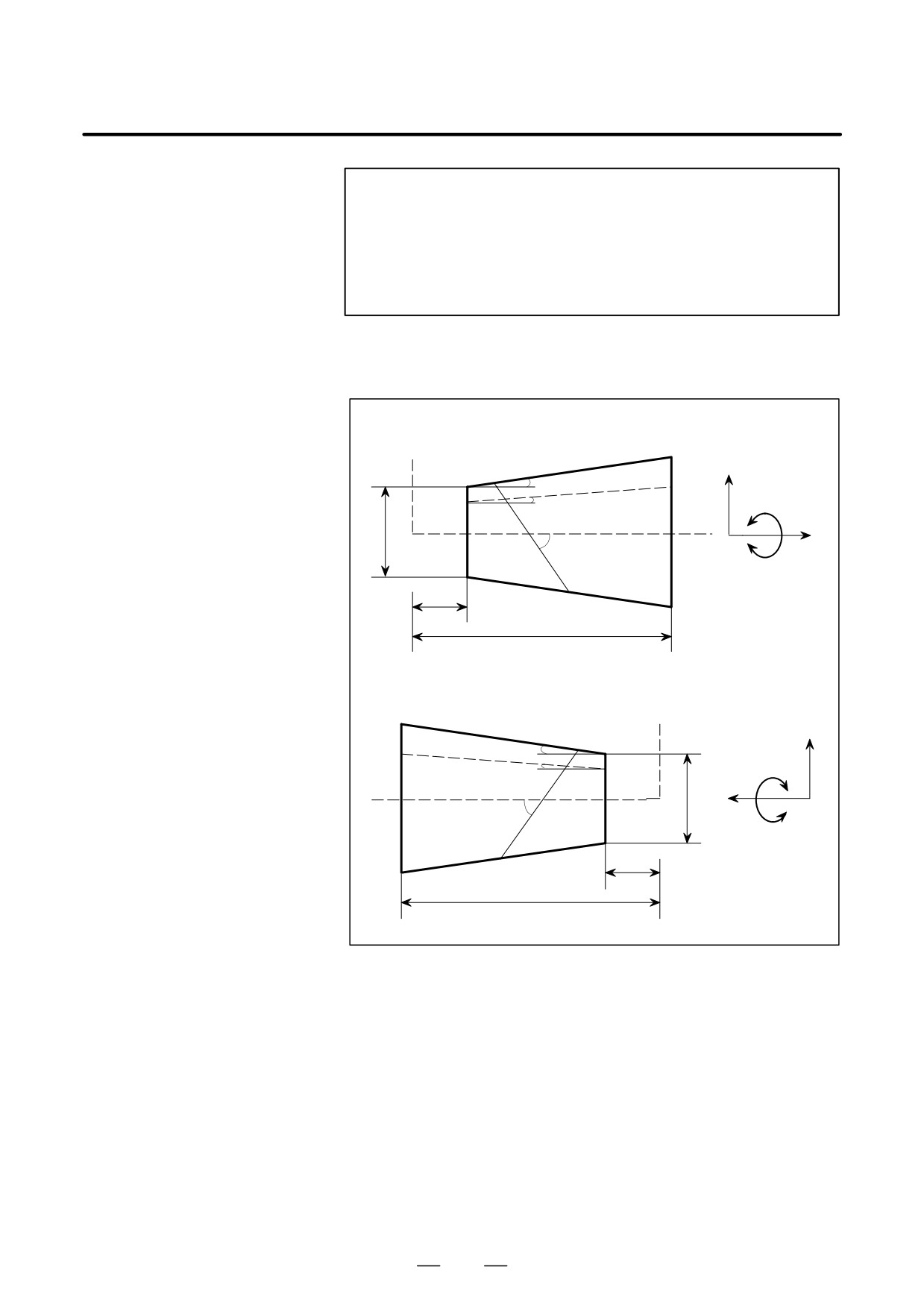
Constant helix machining for producing a tapered figure
Z
I
A
B
r
X
J
U
X
Constant helix machining for producing a reverse tapered figure
Z
I
A
B
r
X
J
U
X
73
4. INTERPOLATION FUNCTIONS
PROGRAMMING
B-63534EN/02
Relational expressions
θ
r
tan (B)
Z (θ) = {
-U tan (I) }
(e
k
–1)
+Z (0)
(3)
⋅⋅⋅⋅⋅⋅⋅⋅⋅⋅⋅
2
tan (I)
θ
r
1
X (θ) = {
-U tan (I) }
(e
k
-1)
⋅⋅⋅⋅⋅⋅⋅⋅⋅⋅⋅⋅⋅⋅⋅⋅⋅⋅⋅⋅
(4)
2
tan (I)
θ
A (q) = (-1)w
360
2π
where
tan (J)
K=
tan (I)
X (q), Z (q), A (q) : Absolute value on the X-axis, Z-axis, and
A-axis from the origin
r
: Left end diameter
U
: Excess length
I
: Taper angle
B
: Groove bottom taper angle
J
: Helix angle
X
: Amount of movement on the linear axis
w
: Helix direction (0: Positive, 1: Negative)
q
: Workpiece rotation angle
From expressions (3) and (4), the following is obtained ;
Z (q) = tan (B) X (q) + Z (0)
⋅⋅⋅⋅⋅⋅⋅⋅⋅⋅⋅⋅⋅⋅⋅⋅⋅⋅⋅
(5)
The groove bottom taper angle (B) is determined from the end
point position on the X-axis and Z-axis according to Expression
5. The amount of movement on the Z-axis is determined from a
groove bottom taper angle (B) and X-axis position.
From Expressions (1) and (4), the following is determined:
R = r/2 - U tan (I)
⋅⋅⋅⋅⋅⋅⋅⋅⋅⋅⋅⋅⋅⋅⋅⋅⋅⋅⋅
(6)
Constant R is determined from the left end diameter (r) and excess
length (U) according to Expression (6). Specify a taper angle (I) in
address I, and specify a helix angle (J) in address J. Note, howev-
er, that a negative value must be specified as the taper angle (I) for
constant helix machining in order to produce a reverse tapered fig-
ure. Select a helix direction with G02.3 or G03.3. The user can
perform constant helix machining to produce a tapered figure or a
reverse tapered figure.
74
B-63534EN/02
PROGRAMMING
4. INTERPOLATION FUNCTIONS
4.12
Either of two types of machining can be selected, depending on the
program command.
SMOOTH
D For those portions where the accuracy of the figure is critical, such as
INTERPOLATION
at corners, machining is performed exactly as specified by the program
(G05.1)
command.
D For those portions having a large radius of curvature where a smooth
figure must becreated, points along the machining path are
interpolated with a smooth curve, calculated from the polygonal lines
specified with the program command (smooth interpolation).
Smooth interpolation can be specified when CDSP (bit 5 of parameter No.
8485) is set to 1 in high-speed contour control mode (between G05
P10000 and G05 P0). Smooth interpolation performed in high-speed
contour control mode is described below. For details of high-speed
contour control, see Section 20.5.
Format
Starting of smooth interpolation mode
G05.1 Q2X0Y0Z0;
Cancelation of smooth interpolation mode
G05.1 Q 0;
Explanations
D Characteristics of
To machine a part having sculptured surfaces, such as metal moldings
smooth interpolation
used in automobiles and airplanes, a part program usually approximates
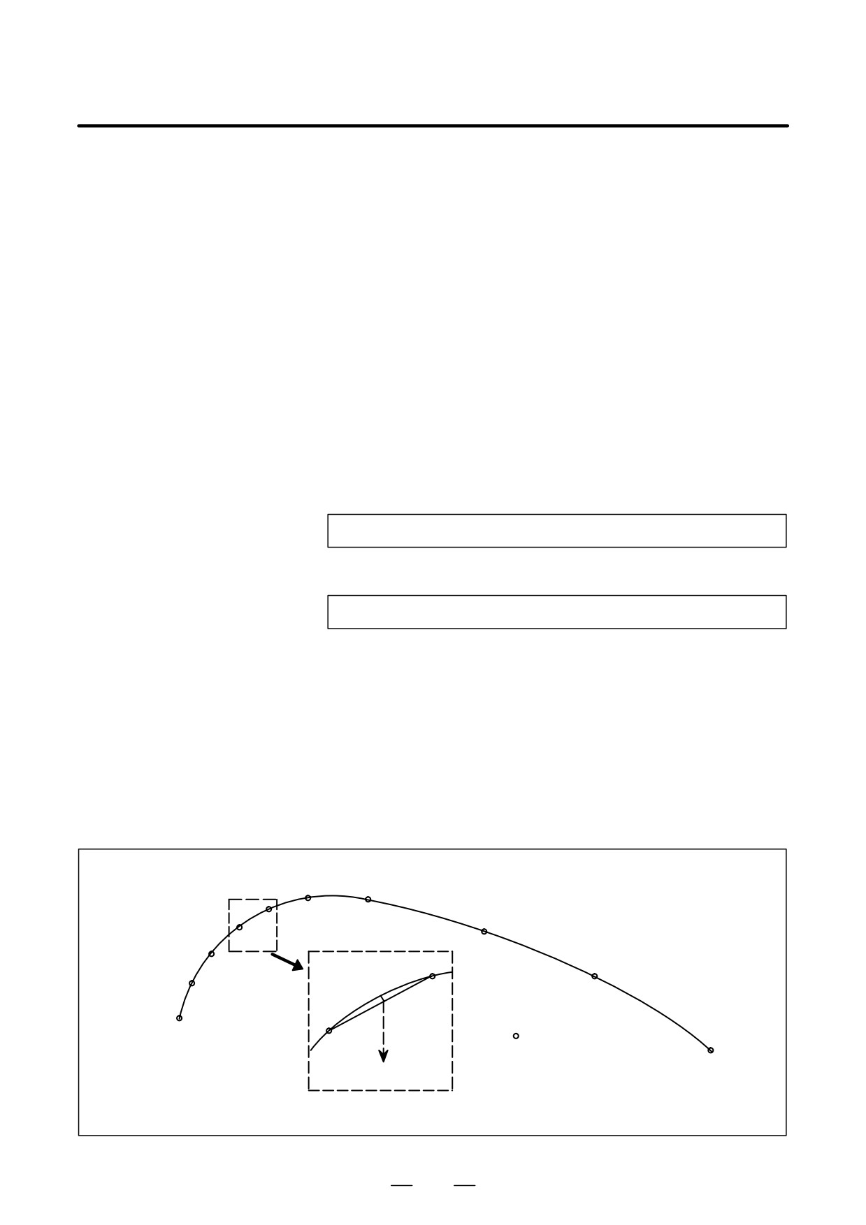
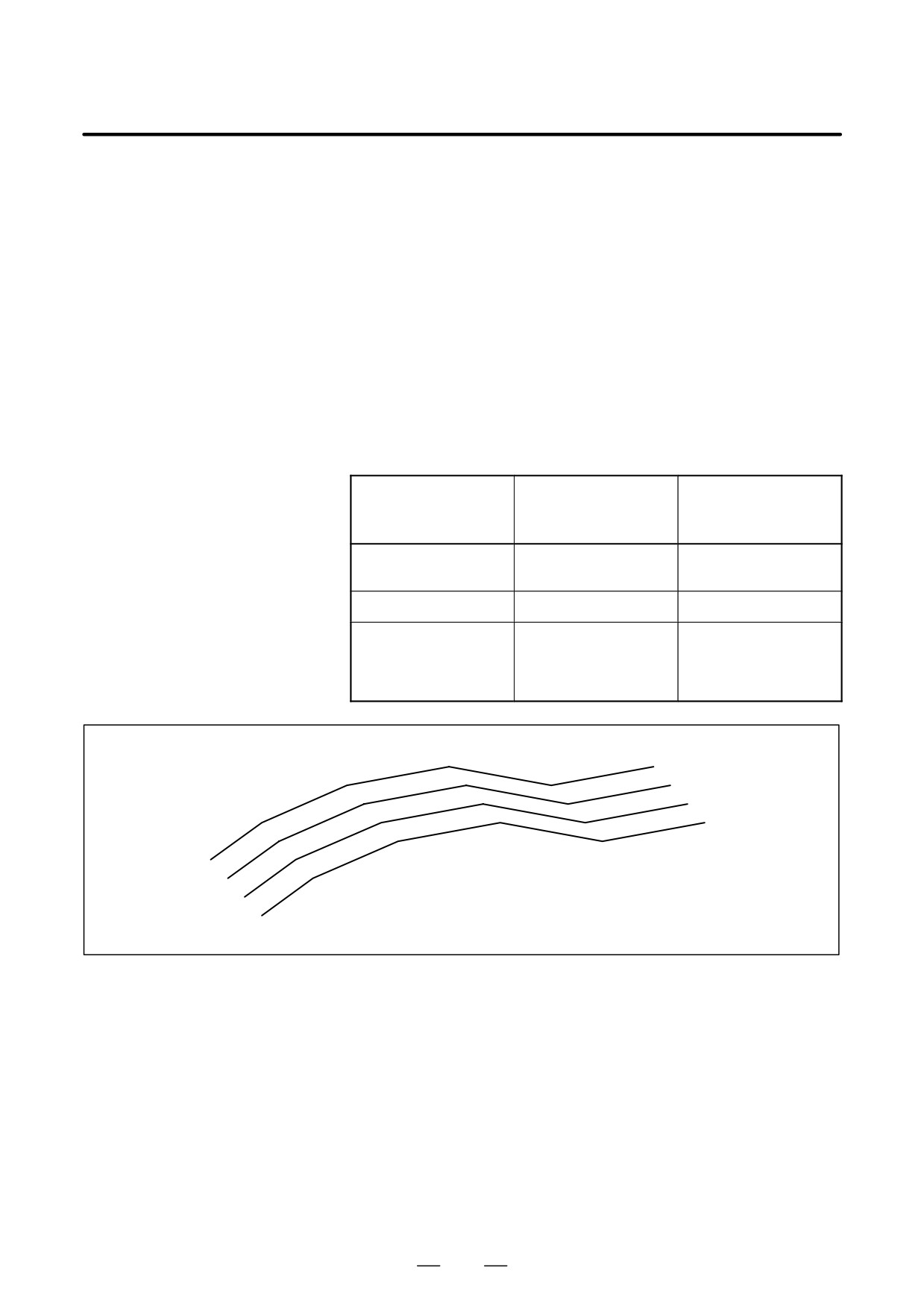
the sculptured surfaces with minute line segments. As shown in the
following figure, a sculptured curve is normally approximated using line
segments with a tolerance of about 10 mm.
Enlarged
: Specified point
10 mm
75
4. INTERPOLATION FUNCTIONS
PROGRAMMING
B-63534EN/02
When a program approximates a sculptured curve with line segments, the
length of each segment differs between those portions that have mainly
a small radius of curvature and those that have mainly a large radius of
curvature. The length of the line segments is short in those portions
having a small radius of curvature, while it is long in those portions
having a large radius of curvature. The high-precision contour control
moves the tool along a programmed path thus enabling highly precise
machining. This means that the tool movement precisely follows the line
segments used to approximate a sculptured curve. This may result in a
non-smooth machined curve if control is applied to machining a curve
where the radius of curvature is large and changes only gradually.
Although this effect is caused by high-precision machining, which
precisely follows a pre-programmed path, the uneven corners that result
will be judged unsatisfactory when smooth surfaces are required.
Portions having
Portions having
Profile
mainly a small radius
mainly a large radius
of curvature
of curvature
Example of machined
Automobile parts
Decorative parts, such
parts
as body side moldings
Length of line segment
Short
Long
Resulting surfaces pro-
Smooth surface even
Uneven surfaces may
duced using high-preci-
when machining is per-
result when machining
sion contour control
formed exactly as speci-
is performed exactly as
fied by a program
specified by a program
Example of uneven surfaces (polygon) resulting from machining
that precisely follows the line segments.
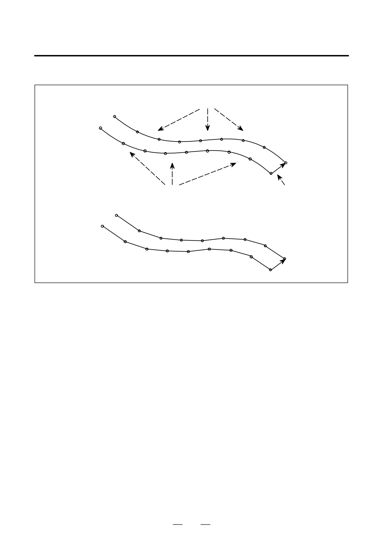
In smooth interpolation mode, the CNC automatically determines,
according to the program command, whether an accurate figure is
required, such as at corners, or a smooth figure is required where the
radius of curvature is large. If a block specifies a travel distance or
direction which differs greatly from that in the preceding block, smooth
interpolation is not performed for that block. Linear interpolation is
performed exactly as specified by the program command. Programming
is thus very simple.
76
B-63534EN/02
PROGRAMMING
4. INTERPOLATION FUNCTIONS
Examples
Interpolated by smooth curve
N17
N16
N15
N13
N12
N14
N11
N1
N2
N10
N3
N5
N6
N4
N7
N8
N9
Interpolated by smooth curve
Linearinterpolation
Linearinterpolation
N17
N16
N15
N13
N12
N14
N11
N1
N2
N10
N3
N4
N5
N6
N7
N8
N9
D Conditions for
Smooth interpolation is performed when all the following conditions are
performing smooth
satisfied. If any of the following conditions is not satisfied for a block,
interpolation
that block is executed without smooth interpolation then the conditions
are checked for the next block.
(1) The machining length specified in the block is shorter than the length
specified with parameter No. 8486.
(2) The machining length is other than 0.
(3) The modes are:
G01
: Linear interpolation
G13.1
: Polar coordinate interpolation cancel
G15
: Polar coordinate command cancel
G40
: Cutter compensation cancel
(except for 3-dimensional tool compensation)
G64
: Cutting mode
G80
: Canned cycle cancel
G94
: Feed per minute
(4) Machining is specified only along the axes specified with G05.1Q2.
(5) The block is judged to be unsuitable for smooth interpolation, as
performed with the internal algorithm of the CNC.
D Commands which cancel
(1) Auxiliary and second auxiliary functions
smooth interpolation
(2) M98, M99 : Subprogram call
M198
: Calling a subprogram in external memory
77
4. INTERPOLATION FUNCTIONS
PROGRAMMING
B-63534EN/02
Limitations
D Controlled axes
Smooth interpolation can be specified only for the X-, Y-, and Z-axes
and any axes parallel to these axes (up to three axes at one time).
D High-precision contour
Commands for turning on and off smooth interpolation mode must be
control mode
executed in high-precision contour control mode.
Examples
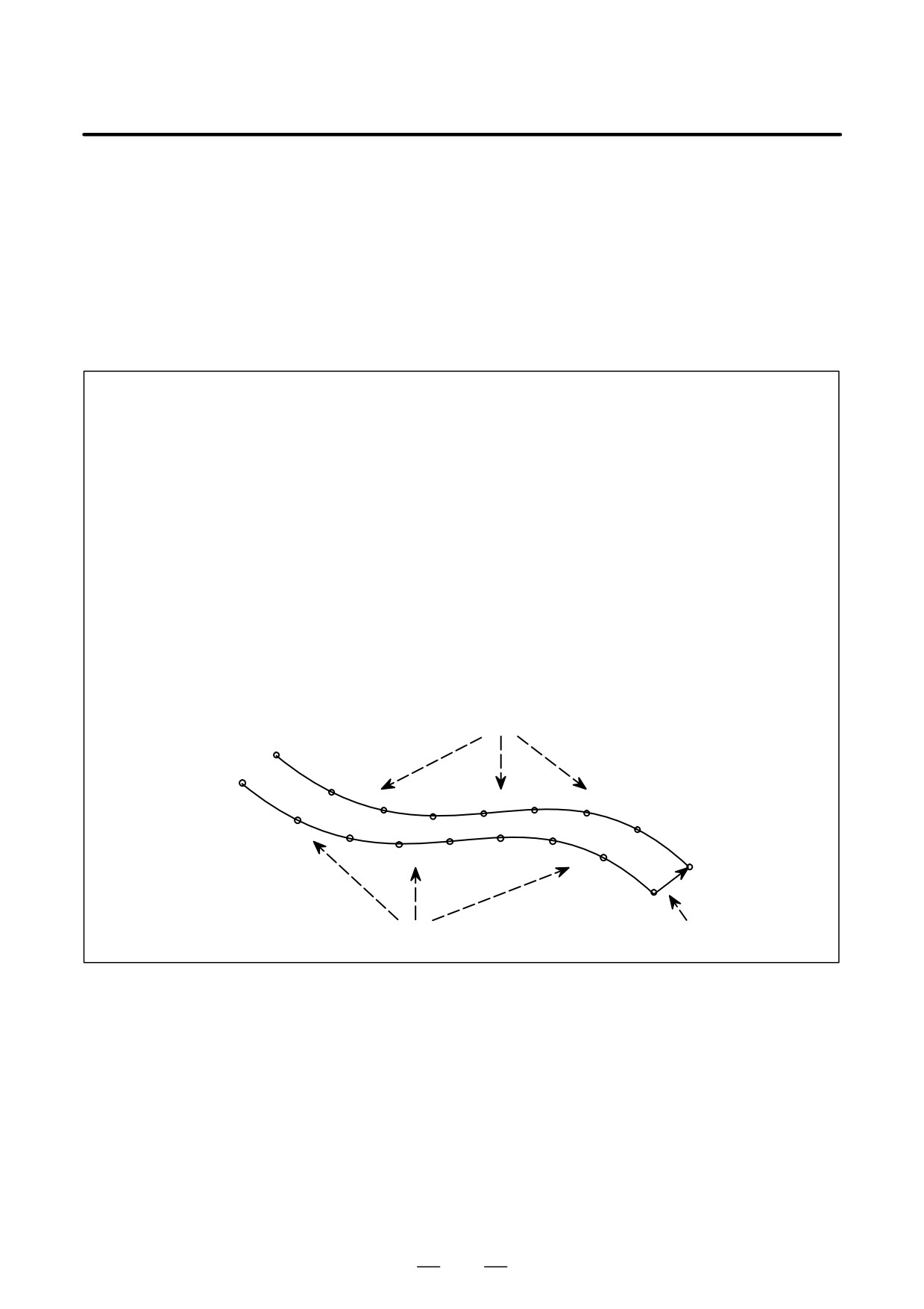
Example program for smooth interpolation
G05 P10000 ;
N10 X-1000 Z350 ;
N11 X-1000 Z175 ;
N12 X-1000 Z25 ;
G91 ;
N13 X-1000 Z- 50 ;
G05. 1 Q2 X0 Y0 Z0 ;
N14 X-1000 Z- 50 ;
N01 G01 X1000 Z-300 ;
N15 X-1000 Z50 ;
N02 X1000 Z-200 ;
N16 X-1000 Z200 ;
N03 X1000 Z-50 ;
N17 X-1000 Z300 ;
N04 X1000 Z50 ;
G05. 1 Q0 ;
N05 X1000 Z50 ;
N06 X1000 Z-25 ;
N07 X1000 Z-175 ;
G05 P0 ;
N08 X1000 Z-350 ;
N09 Y1000 ;
Interpolated by smooth curve
N17
N16
N15
N13
N12
N14
N11
N1
N2
N10
N3
N5
N6
N4
N7
N8
N9
Interpolated by smooth curve
Linearinterpolation
78
B-63534EN/02
PROGRAMMING
4. INTERPOLATION FUNCTIONS
4.13
Many computer-aided design (CAD) systems used to design metal dies
for automobiles and airplanes utilize non-uniform rational B-spline
NURBS
(NURBS) to express a sculptured surface or curve for the metal dies.
INTERPOLATION
This function enables NURBS curve expression to be directly specified
(G06.2)
to the CNC. This eliminates the need for approximating the NURBS
curve with minute line segments. This offers the following advantages:
1.No error due to approximation of a NURBS curve by small line
segments
2.Short part program
3.No break between blocks when small blocks are executed at high speed
4.No need for high-speed transfer from the host computer to the CNC
When this function is used, a computer-aided machining (CAM) system
creates a NURBS curve according to the NURBS expression output from
the CAD system, after compensating for the length of the tool holder, tool
diameter, and other tool elements. The NURBS curve is programmed in
the NC format by using these three defining parameters: control point,
weight, and knot.
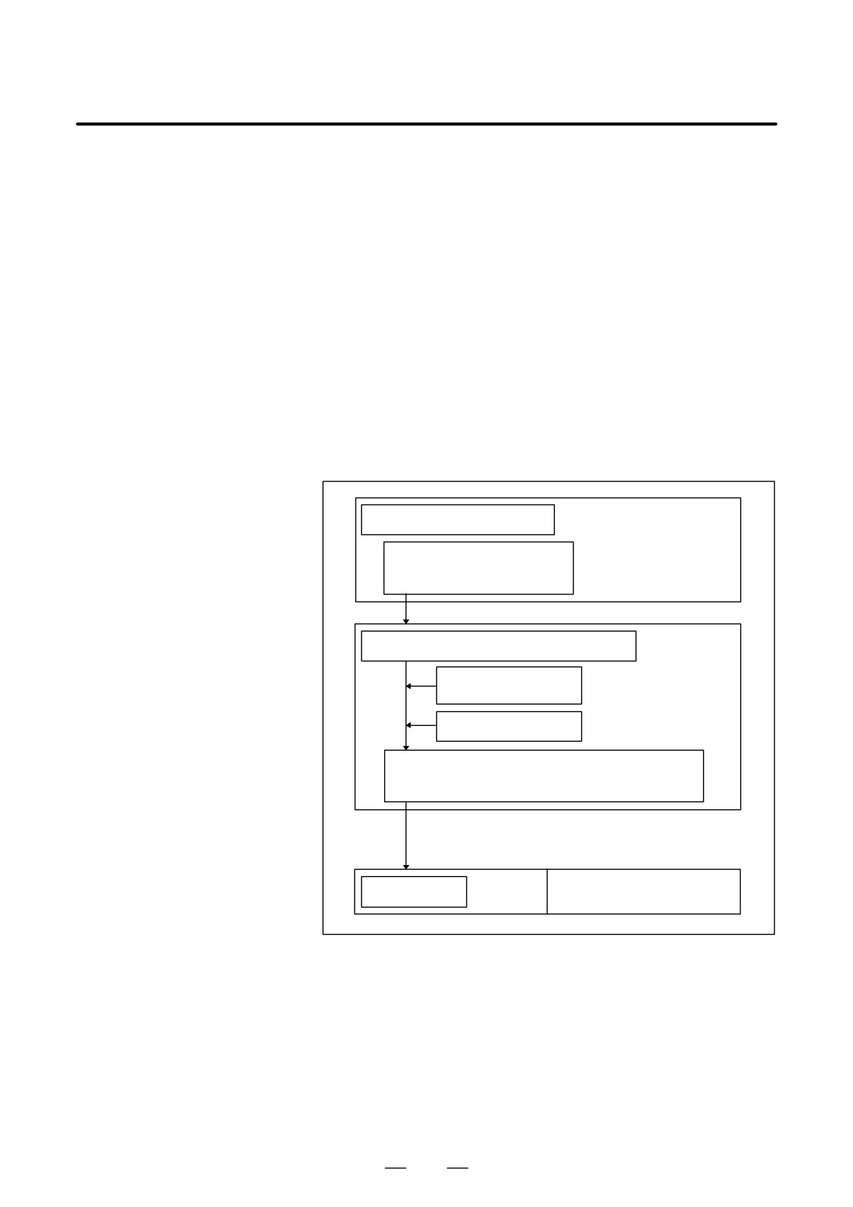
CAD
(Designing a metal die)
Generating a metal die surface
(NURBS surface or curve)
CAM
(Creating an NC part program)
Studying the machining
method and others
Tool compensation file
NC part program after tool compensation
(NURBS curve)
NURBS curve
(control point, weight, knot)
CNC equipment
Machine tool
Fig. 4.13 NC part program for machining a metal die according to a
NURBS curve
NURBS interpolation must be specified in high-precision contour
control mode (between G05 P10000 and G05 P0). The CNC executes
NURBS interpolation while smoothly accelerating or decelerating the
movement so that the acceleration on each axis will not exceed the
allowable maximum acceleration of the machine. In this way, the CNC
automatically controls the speed in order to prevent excessive strain being
imposed on the machine. For details of high-precision contour control,
see Section II-19.8.
79

4. INTERPOLATION FUNCTIONS
PROGRAMMING
B-63534EN/02
Format
G05 P10000 ;
(Start high-precision contour control mode)
G06.2 [P_] K_ X_ Y_ Z_ [R_] [F_] ;
K_ X_ Y_ Z_ [R_] ;
K_ X_ Y_ Z_ [R_] ;
K_ X_ Y_ Z_ [R_] ;
K_ X_ Y_ Z_ [R_] ;
K_ ;
K_ ;
G01
G05 P0
;
(End high-precision contour control mode)
G06.2
:
Start NURBS interpolation mode
P_
:
Rank of NURBS curve
X_ Y_ Z_ : Control point
R_
:
Weight
K_
:
Knot
F_
:
Feedrate
Explanations
D NURBS interpolation
NURBS interpolation mode is selected when G06.2 is programmed in
mode
high-precision contour control mode. G06.2 is a modal G code of group
01. NURBS interpolation mode ends when a G code of group 01 other
than G06.2
(G00, G01, G02, G03, etc.) is specified. NURBS
interpolation mode must end before the command for ending
high-precision contour control mode is programmed.
D Rank of NURBS
A rank of NURBS can be specified with address P. The rank setting, if
any, must be specified in the first block. If the rank setting is omitted, a
rank of four (degree of three) is assumed for NURBS. The valid data
range for P is 2 to 4. The P values have the following meanings:
P2: NURBS having a rank of two (degree of one)
P3: NURBS having a rank of three (degree of two)
P4: NURBS having a rank of four (degree of three) (default)
This rank is represented by k in the defining expression indicated in the
description of NURBS curve below. For example, a NURBS curve
having a rank of four has a degree of three. The NURBS curve can be
expressed by the constants t3, t2, and t1.
D Weight
The weight of a control point programmed in a single block can be
defined. When the weight setting is omitted, a weight of 1.0 is assumed.
80
B-63534EN/02
PROGRAMMING
4. INTERPOLATION FUNCTIONS
D Knot
The number of specified knots must equal the number of control points
plus the rank value. In the blocks specifying the first to last control points,
each control point and a knot are specified in an identical block. After
these blocks, as many blocks (including only a knot) as the rank value are
specified. The NURBS curve programmed for NURBS interpolation
must start from the first control point and end at the last control point. The
first k knots (where k is the rank) must have the same values as the last
k knots (multiple knots). If the absolute coordinates of the start point of
NURBS interpolation do not match the position of the first control point,
P/S alarm No. 5117 is issued. (To specify incremental values, G06.2 X0
Y0 Z0 K_ must be programmed.)
D NURBS curve
Using these variables:
k
: Rank
Pi
: Control point
Wi : Weight
Xi
: Knot (Xi v Xi + 1)
Knot vector [X0, X1, ..., Xm] (m = n + k)
t
: Spline parameter,
the spline basis function N can be expressed with the de Boor-Cox
recursive formula, as indicated below:
1
(xi v t v xi)1
)
Ni,1(t)
+ NJ
0
(t t xi , xi)1 t t)
Ni,k-1(t)
Ni,k(t)
+ (t-xi)
) (xi)k-t)Ni)1,k-1(t)
xi)k-1
-xi
xi)k-xi)1
The NURBS curve P(t) of interpolation can be expressed as follows:
n
S
Ni,k(t)wiPi
P(t)
+i+0
n
S
Ni,k(t)wi
i+0
(x0 v tv xm)
D Reset
A reset during NURBS interpolation results in the clear state. The modal
code of group 1 enters the state specified in the G01 bit (bit 0 of parameter
3402).
Limitations
D Controlled axes
NURBS interpolation can be performed on up to three axes. The axes of
NURBS interpolation must be specified in the first block. A new axis
cannot be specified before the beginning of the next NURBS curve or
before NURBS interpolation mode ends.
D Command in NURBS
In NURBS interpolation mode, any command other than the NURBS
interpolation mode
interpolation command (miscellaneous function and others) cannot be
specified.
D Manual intervention
If manual intervention is attempted while manual absolute mode is set,
P/S alarm No. 5118 is issued.
D Cutter compensation
Cutter compensation cannot be simultaneously executed. NURBS
interpolation can only be specified after cutter compensation has been
canceled.
81
4. INTERPOLATION FUNCTIONS
PROGRAMMING
B-63534EN/02
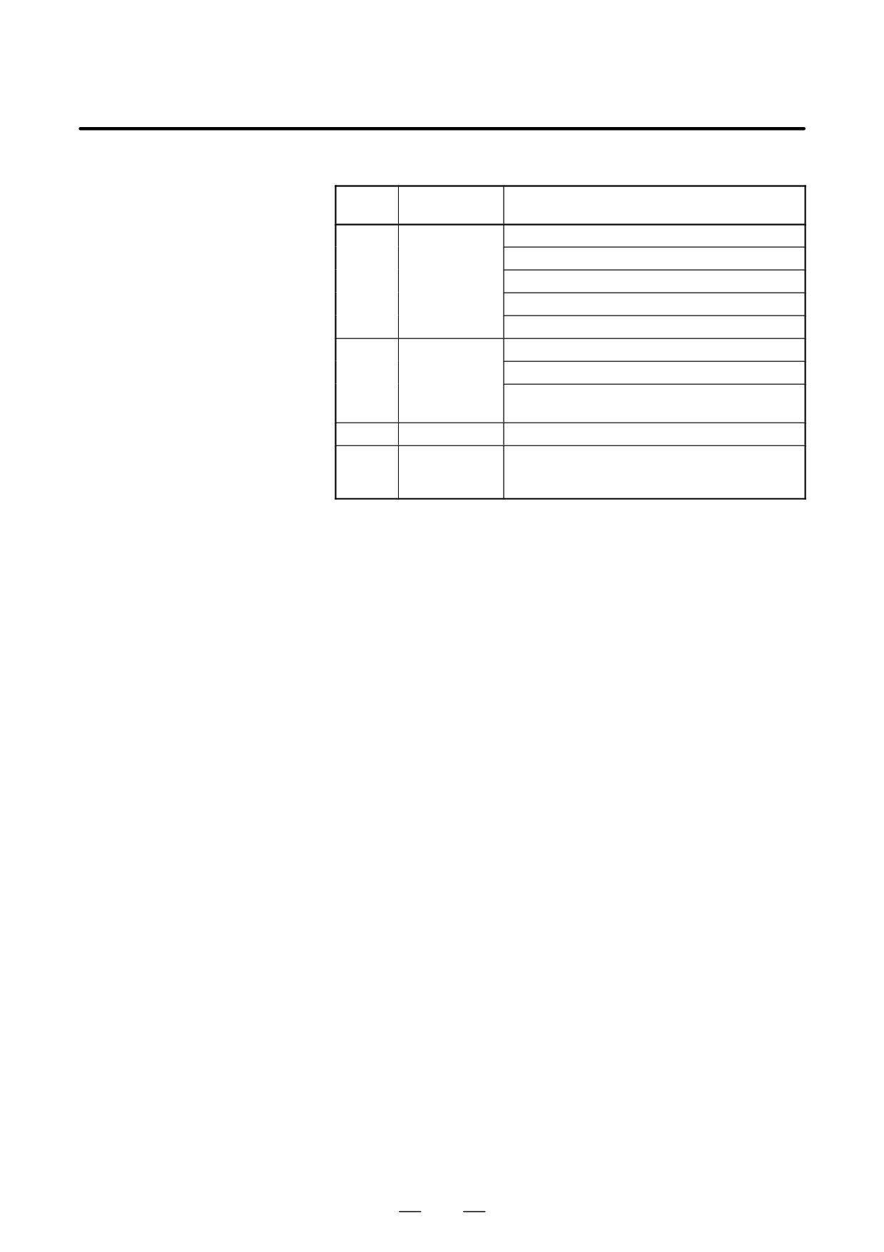
Alarms
Displayed
No.
Description
message
PS5115
SPL: Error
An illegal rank is specified.
No knot is specified.
An illegal knot is specified.
Too many axes are specified.
Other program error.
PS5116
SPL: Error
A look-ahead block contains a program error.
The knot does not increase at a constant rate.
An inhibited mode is specified in NURBS inter-
polation mode.
PS5117
SPL: Error
The first NURBS control point is illegal.
PS5118
SPL: Error
An attempt was made to resume NURBS inter-
polation after manual intervention in manual
absolute mode.
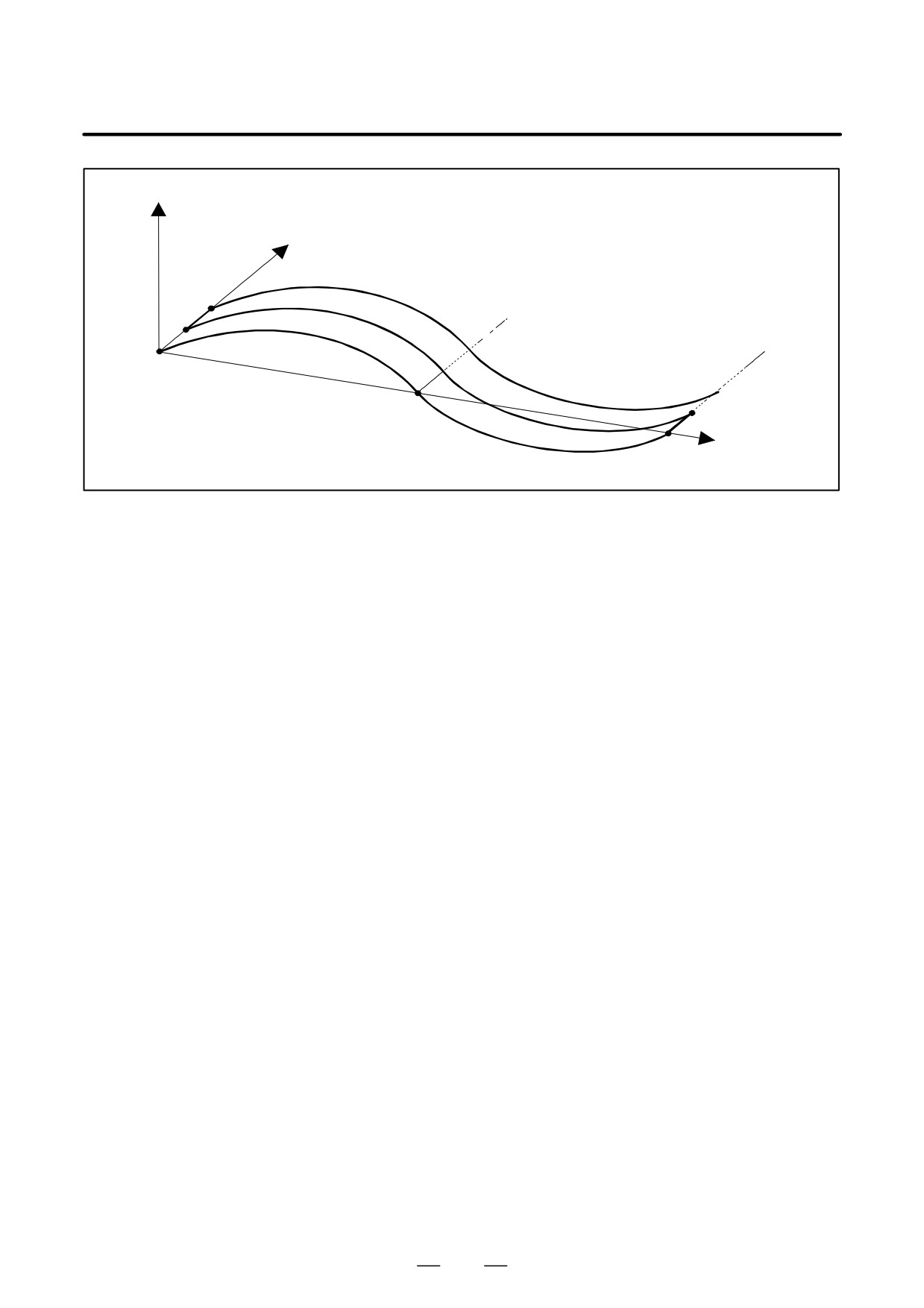
Example
<Sample NURBS interpolation program>
G05 P10000;
G90;
G06.2 K0. X0. Z0.;
K0. X300. Z100.;
K0. X700. Z100.;
K0. X1300. Z-100.;
K0.5 X1700. Z-100.;
K0.5 X2000. Z0.;
K1.0;
K1.0;
K1.0;
K1.0;
G01 Y0.5;
G06.2 K0. X2000. Z0.;
K0. X1700. Z-100.;
K0. X1300. Z-100.;
K0. X700. Z100.;
K0.5 X300. Z100.;
K0.5 X0.
Z0.;
K1.0;
K1.0;
K1.0;
K1.0;
G01 Y0.5;
G06.2
G01 ...
G05P0;
82
B-63534EN/02
PROGRAMMING
4. INTERPOLATION FUNCTIONS
Z
Y
1000.
X
2000.
83
4. INTERPOLATION FUNCTIONS
PROGRAMMING
B-63534EN/02
4.14
In helical interpolation, when pulses are distributed with one of the
circular interpolation axes set to a hypothetical axis, sine interpolation is
HYPOTHETICAL AXIS
enabled.
INTERPOLATION
When one of the circular interpolation axes is set to a hypothetical axis,
(G07)
pulse distribution causes the speed of movement along the remaining axis
to change sinusoidally. If the major axis for threading (the axis along
which the machine travels the longest distance) is set to a hypothetical
axis, threading with a fractional lead is enabled. The axis to be set as the
hypothetical axis is specified with G07.
Format
G07 a 0; Hypothetical axis setting
G07 a 1; Hypothetical axis cancel
Where, a is any one of the addresses of the controlled axes.
Explanations
D Sine interpolation
The a axis is regarded as a hypothetical axis for the period of time from
the G07 a 0 command until the G07 a 1 command appears.
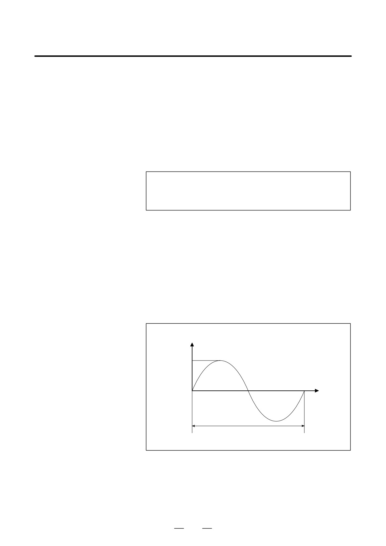
Suppose sine interpolation is performed for one cycle in the YZ plane.
The hypothetical axis is then the X axis.
X2 + Y2 = r2 (r is the radius of an arc.)
2p
Y = r SIN (
Z )
1
(1 is the distance traveled along the Z-axis in one cycle.)
Y
r
p
2p
Z
0
p
2
1
D Interlock, stroke limit,
Interlock, stroke limit, and external deceleration can also apply to the
and external
hypothetical axis.
deceleration
D Handle interrupt
An interrupt caused by the handle also applies to the hypothetical axis.
This means that movement for a handle interrupt is performed.
84
B-63534EN/02
PROGRAMMING
4. INTERPOLATION FUNCTIONS
Limitations
D Manual operation
The hypothetical axis can be used only in automatic operation. In manual
operation, it is not used, and movement takes place.
D Move command
Specify hypothetical axis interpolation only in the incremental mode.
D Coordinate rotation
Hypothetical axis interpolation does not support coordinate rotation.
Examples
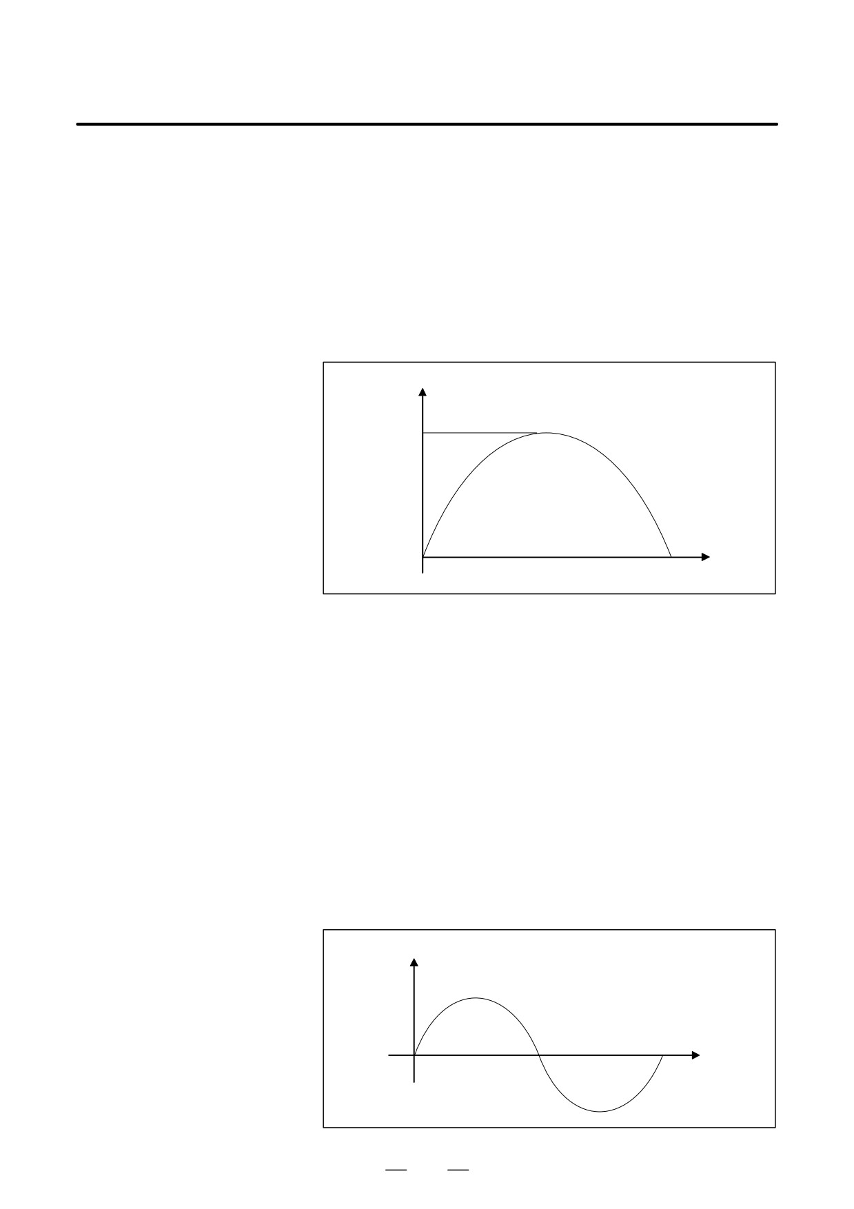
D Sine interpolation
Y
10.0
Z
0
20.0
N001 G07 X0 ;
N002 G91 G17 G03 X-20.2 Y0.0 I-10.0 Z20.0 F100 ;
N003 G01 X10.0 ;
N004 G07 X1 ;
From the N002 to N003 blocks, the X-axis is set to a hypothetical axis.
The N002 block specifies helical cutting in which the Z-axis is the linear
axis. Since no movement takes place along the X axis, movement along
the Y-axis is performed while performing sine interpolation along the
Z-axis.
In the N003 block, there is no movement along the X-axis, and so the
machine dwells until interpolation terminates.
D Changing the feedrate to
(Sample program)
form a sine curve
G07Z0 ;
The Z-axis is set to a hypothetical axis.
G02X0Z0I10.0F4. ; The feedrate on the X-axis changes sinusoidally.
G07Z1 ;
The use of the Z-axis as a hypothetical axis is
canceled.
F
4.0
Xt
85
4. INTERPOLATION FUNCTIONS
PROGRAMMING
B-63534EN/02
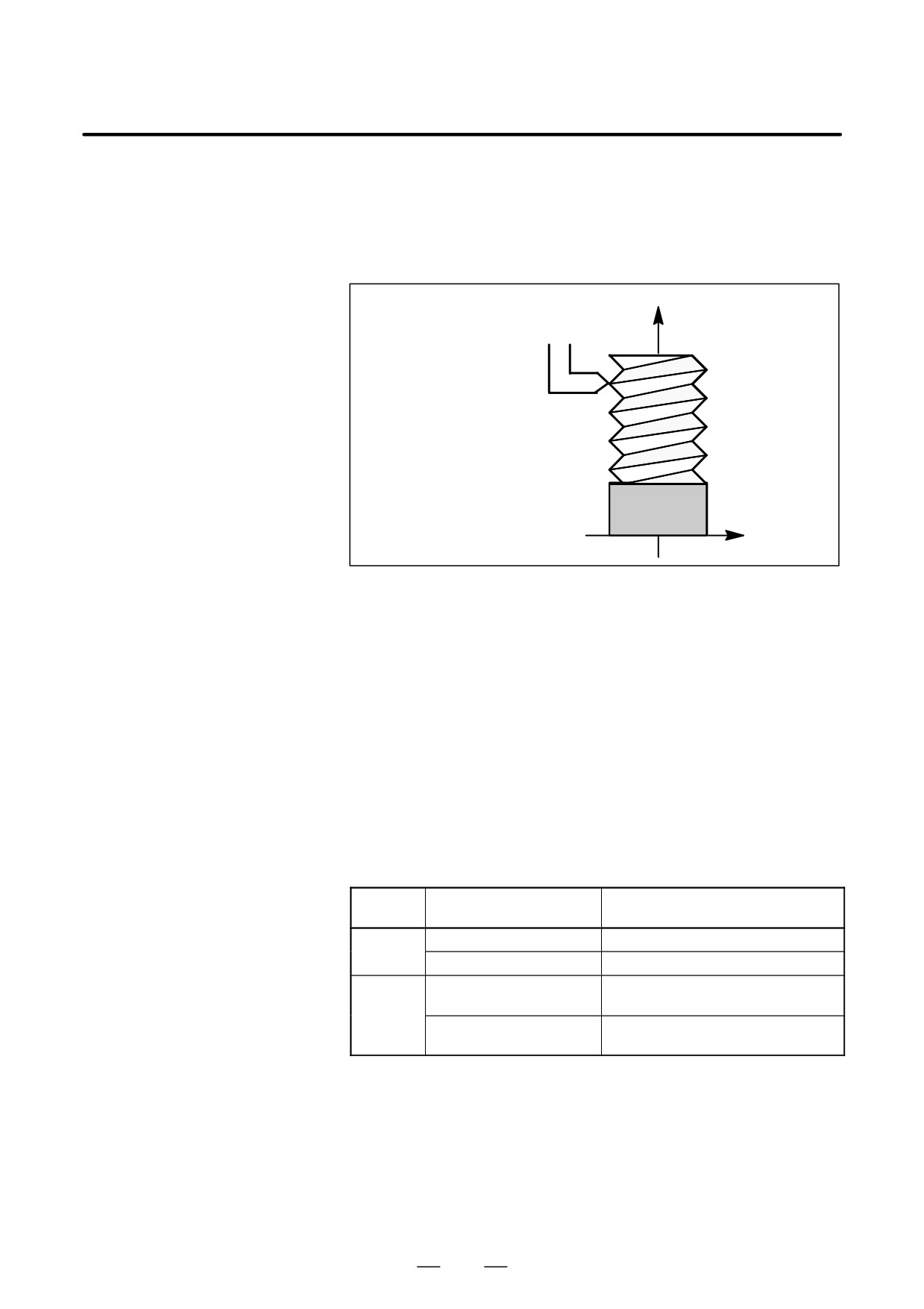
Straight threads with a constant lead can be cut. The position coder
4.15
mounted on the spindle reads the spindle speed in real-time. The read
THREAD CUTTING
spindle speed is converted to the feedrate per minute to feed the tool.
(G33)
Format
Z
G33
I
P
_ F_ ;
F : Long axis direction lead
Workpiece
X
Explanations
In general, thread cutting is repeated along the same tool path in rough
cutting through finish cutting for a screw. Since thread cutting starts when
the position coder mounted on the spindle outputs a 1-turn signal,
threading is started at a fixed point and the tool path on the workpiece is
unchanged for repeated thread cutting. Note that the spindle speed must
remain constant from rough cutting through finish cutting. If not,
incorrect thread lead will occur.
In general, the lag of the servo system, etc. will produce somewhat
incorrect leads at the starting and ending points of a thread cut. To
compensate for this, a thread cutting length somewhat longer than
required should be specified.
Table 4.15 (a) lists the ranges for specifying the thread lead.
Table. 4.15 (a) Ranges of lead sizes that can be specified
Least command
Command value range of the lead
increment
0.001 mm
F1 to F50000 (0.01 to 500.00mm)
mm input
0.0001 mm
F1 to F50000 (0.01 to 500.00mm)
F1 to F99999
0.0001 inch
(0.0001 to 9.9999inch)
Inch input
F1 to F99999
0.00001 inch
(0.0001 to 9.9999inch)
86

B-63534EN/02
PROGRAMMING
4. INTERPOLATION FUNCTIONS
NOTE
1
The spindle speed is limited as follows :
Maximum feedrate
1 x spindle speed x
Thread lead
Spindle speed : min-1
Thread lead : mm or inch
Maximum feedrate : mm/min or inch/min ; maximum command-specified feedrate for
feed-per-minute mode or maximum feedrate that is determined based on mechanical
restrictions including those related to motors, whichever is smaller
2
Cutting feedrate override is not applied to the converted feedrate in all machining process from
rough cutting to finish cutting. The feedrate is fixed at 100%
3
The converted feedrate is limited by the upper feedrate specified.
4
Feed hold is disabled during threading. Pressing the feed hold key during thread cutting causes
the machine to stop at the end point of the next block after threading (that is, after the G33 mode
is terminated)
Examples
Thread cutting at a pitch of 1.5mm
G33 Z10. F1.5;
87

4. INTERPOLATION FUNCTIONS
PROGRAMMING
B-63534EN/02
Linear interpolation can be commanded by specifying axial move
4.16
following the G31 command, like G01. If an external skip signal is input
SKIP FUNCTION
during the execution of this command, execution of the command is
(G31)
interrupted and the next block is executed.
The skip function is used when the end of machining is not programmed
but specified with a signal from the machine, for example, in grinding. It
is used also for measuring the dimensions of a workpiece.
Format
G31
_ ;
IP
G31: One-shot G code (If is effective only in the block in which it
is specified)
Explanations
The coordinate values when the skip signal is turned on can be used in a
custom macro because they are stored in the custom macro system
variable #5061 to #5068, as follows:
#5061 X axis coordinate value
#5062 Y axis coordinate value
#5063 Z axis coordinate value
#5064 4th axis coordinate value
#5065 5th axis coordinate value
#5066 6th axis coordinate value
#5067 7th axis coordinate value
#5068 8th axis coordinate value
WARNING
Disable feedrate override, dry run, and automatic
acceleration/deceleration
(however, these become
available by setting the parameter SKF No.6200#7 to 1.)
when the feedrate per minute is specified, allowing for an
error in the position of the tool when a skip signal is input.
These functions are enabled when the feedrate per rotation
is specified.
NOTE
If G31 command is issued while cutter compensation C is
applied, an P/S alarm of No.035 is displayed. Cancel the
cutter compensation with the G40 command before the G31
command is specified.
88
B-63534EN/02
PROGRAMMING
4. INTERPOLATION FUNCTIONS
Examples
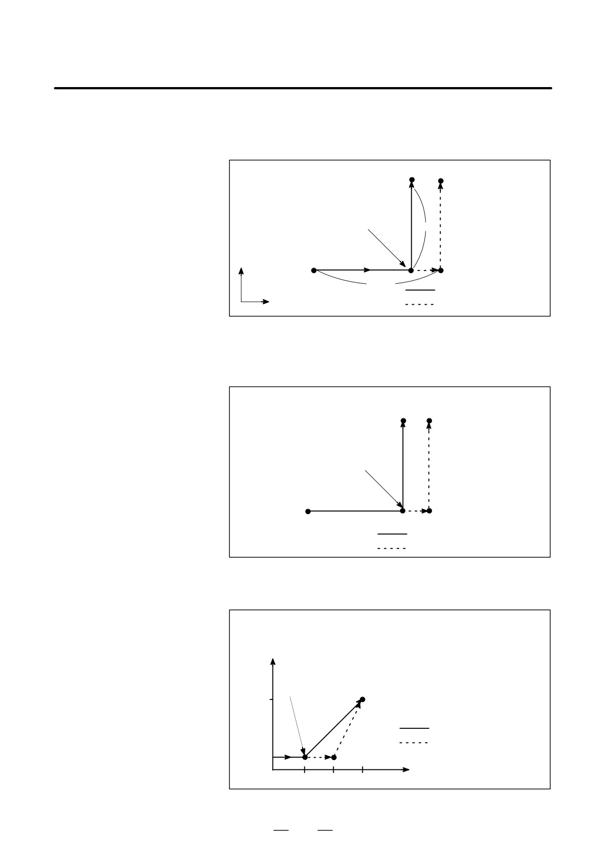
D The next block to G31 is
an incremental
command
G31
G91X100.0 F100;
Y50.0;
Skip signal is input here
50.0
Y
100.0
Actual motion
X
Motion without skip signal
Fig. 4.16 (a) The next block is an incremental command
D The next block to G31 is
an absolute command
for 1 axis
G31
G90X200.00 F100;
Y100.0
Y100.0;
Skip signal is input here
X200.0
Actual motion
Motion without skip signal
Fig. 4.16 (b) The next block is an absolute command for 1 axis
D The next block to G31 is
an absolute command
for 2 axes
G31
G90X200.0 F100;
X300.0 Y100.0;
Y
Skip signal is input here
100
(300,100)
Actual motion
Motion without skip signal
X
100
200
300
Fig 4.16 (c) The next block is an absolute command for 2 axes
89

4. INTERPOLATION FUNCTIONS
PROGRAMMING
B-63534EN/02
4.17
In a block specifying P1 to P4 after G31, the multistage skip function
stores coordinates in a custom macro variable when a skip signal (4-point
MULTISTAGE SKIP
or 8-point ; 8-point when a high-speed skip signal is used) is turned on.
(G31)
Parameters No. 6202 to No. 6205 can be used to select a 4-point or
8-point (when a high-speed skip signal is used) skip signal. One skip
signal can be set to match multiple Pn or Qn (n=1,2,3,4) as well as to
match a Pn or Qn on a one-to-one basis. Parameters DS1 to DS8 (No.
6206 #0A#7) can be used for dwell.
A skip signal from equipment such as a fixed-dimension size measuring
instrument can be used to skip programs being executed.
In plunge grinding, for example, a series of operations from rough
machining to spark-out can be performed automatically by applying a
skip signal each time rough machining, semi-fine machining,
fine-machining, or spark-out operation is completed.
Format
Move command
G31 IIP__ F __ P __ ;
_ : End point
IP
F_ : Feedrate
P_ : P1-P4
Dwell
G04 X (P)__ (Q__) ;
X(P)_ : Dwell time
Q_ : Q1 - Q4
Explanations
Multistage skip is caused by specifying P1, P2, P3, or P4 in a G31 block.
For an explanation of selecting (P1, P2, P3, or P4), refer to the manual
supplied by the machine tool builder.
Specifying Q1, Q2, Q3, or Q4 in G04 (dwell command) enables dwell
skip in a similar way to specifying G31. A skip may occur even if Q is
not specified. For an explanation of selecting (Q1, Q2, Q3, or Q4), refer
to the manual supplied by the machine tool builder.
D Correspondence to skip
Parameter Nos. 6202 to 6205 can be used to specify whether the 4-point
signals
or 8-point skip signal is used (when a high-speed skip signal is used).
Specification is not limited to one-to-one correspondence. It is possible
to specify that one skip signal correspond to two or more Pn’s or Qn’s
(n=1, 2, 3, 4). Also, bits 0 (DS1) to 7 (DS8) of parameter No. 6206 can
be used to specify dwell.
CAUTION
Dwell is not skipped when Qn is not specified and
parameters DS1-DS8 (No. 6206#0-#7) are not set.
90
B-63534EN/02
PROGRAMMING
4. INTERPOLATION FUNCTIONS
4.18
The skip function operates based on a high-speed skip signal (connected
directly to the NC; not via the PMC) instead of an ordinary skip signal.
HIGH SPEED SKIP
In this case, up to eight signals can be input.
SIGNAL (G31)
Delay and error of skip signal input is 0 - 2 msec at the NC side (not
considering those at the PMC side).
This high-speed skip signal input function keeps this value to 0.1 msec
or less, thus allowing high precision measurement.
For details, refer to the appropriate manual supplied from the machine
tool builder.
Format
G31 IP_ ;
G31: One-shot G code (If is effective only in the block in which it is
specified)
91
4. INTERPOLATION FUNCTIONS
PROGRAMMING
B-63534EN/02
4.19
The continuous high-speed skip function enables reading of absolute
coordinates by using the high-speed skip signal. Once a high-speed skip
CONTINUOUS
signal has been input in a G31P90 block, absolute coordinates are read
HIGH-SPEED SKIP
into custom macro variables #5061 to #5068. The input of a skip signal
FUNCTION (G31)
does not stops axial movement, thus enabling reading of the coordinates
of two or more points.
The rising and falling edges of the high-speed skip signal can be used as
a trigger, depending on the parameter BHIS (No. 6201#5) setting.
Format
G31 P90 a__ F__
a__: Skip axis address and amount of travel
Only one axis can be specified. G31 is a one-shot G code.
Explanations
D Custom macro variables
Once a high-speed skip signal has been input in a G31P90 block, absolute
coordinates are read into custom macro variables #5061 to #5068. These
variables are immediately updated once the tool reaches the next skip
position. The feedrate must, therefore, be specified such that the tool does
not reach the next skip position before the application completes reading
of the variables. For details of the application, refer to the appropriate
manual supplied from the machine tool builder.
#5061
Coordinate along the first axis
#5062
Coordinate along the second axis
#5063
Coordinate along the third axis
L
#5068
Coordinate along the eighth axis
D High-speed skip signal
This function is enabled only when a high-speed skip signal is used.
The high-speed skip signal to be used is selected with bits 0 to 7 of
parameter No. 6208 (9S1 to 9S8).
D End of block
The G31P90 block is terminated when the tool reaches the end point.
Limitations
D Controlled axes
Only one axis can be specified in the block for the continuous high-speed
skip function (G31P90). If two or more axes are specified, P/S alarm No.
5068 is issued.
92
B-63534EN/02
PROGRAMMING
5. FEED FUNCTIONS
FEED FUNCTIONS
5
93
5. FEED FUNCTIONS
PROGRAMMING
B-63534EN/02
The feed functions control the feedrate of the tool. The following two feed
5.1
functions are available:
GENERAL
D Feed functions
1. Rapid traverse
When the positioning command (G00) is specified, the tool moves at
a rapid traverse feedrate set in the CNC (parameter No. 1420).
2. Cutting feed
The tool moves at a programmed cutting feedrate.
D Override
Override can be applied to a rapid traverse rate or cutting feedrate using
the switch on the machine operator’s panel.
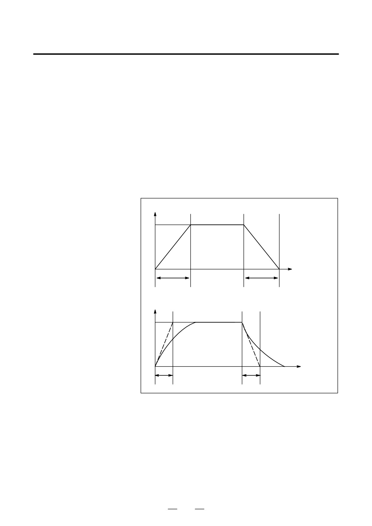
D Automatic acceleration/
To prevent a mechanical shock, acceleration/deceleration is automatically
deceleration
applied when the tool starts and ends its movement (Fig. 5.1 (a)).
Rapid traverse rate
FR : Rapid traverse
FR
rate
TR
: Acceleration/
deceleration time
constant for rap-
id traverse rate
0
Time
TR
TR
Feed rate
FC
: Feedrate
FC
TC : Acceleration/
deceleration time
constant for a cut-
ting feedrate
0
Time
TC
TC
Fig. 5.1 (a) Automatic acceleration/deceleration (example)
94
B-63534EN/02
PROGRAMMING
5. FEED FUNCTIONS
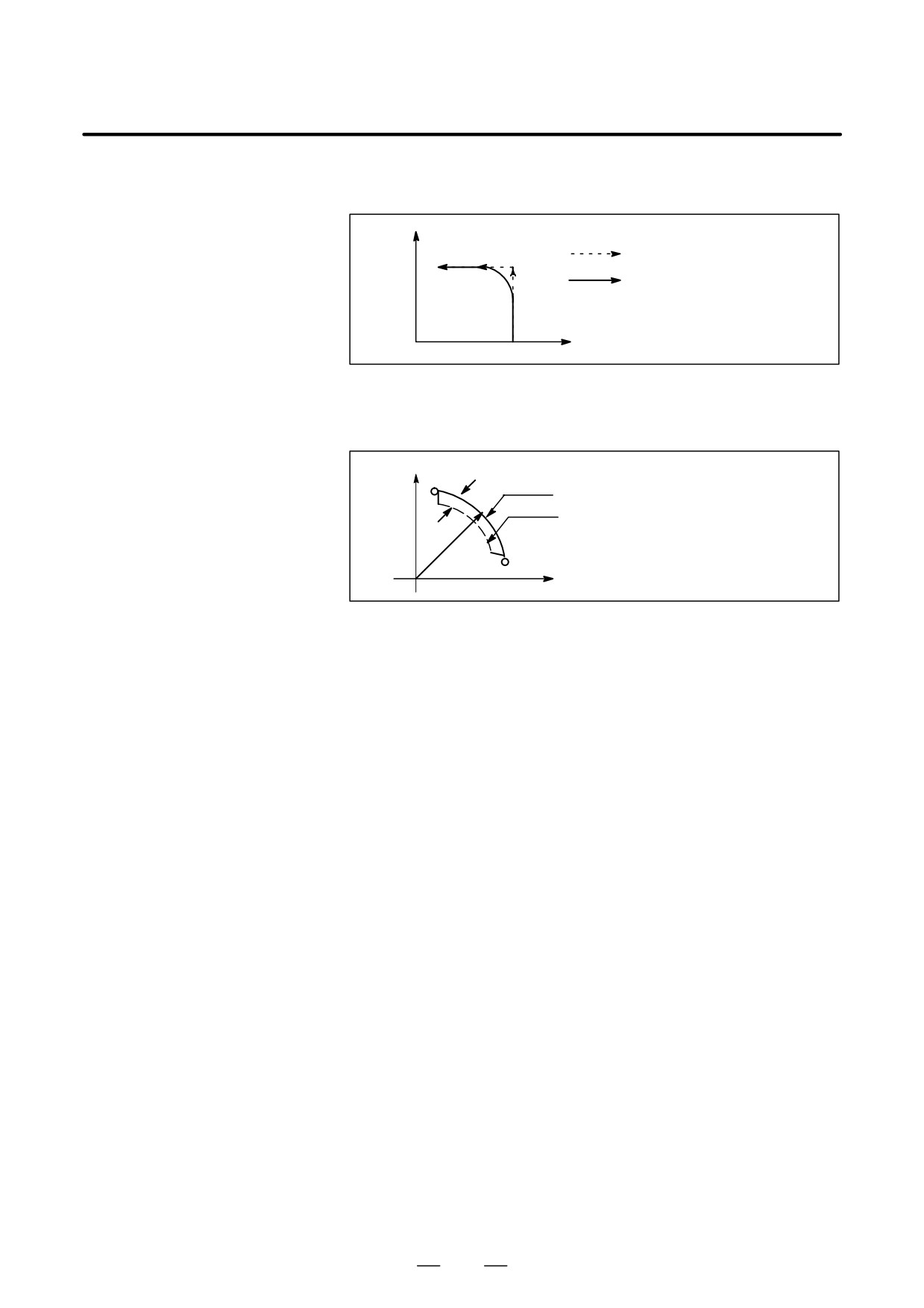
D Tool path in a cutting
If the direction of movement changes between specified blocks during
feed
cutting feed, a rounded-corner path may result (Fig. 5.1 (b)).
Y
Programmed path
Actual tool path
0
X
Fig. 5.1 (b) Example of Tool Path between Two Blocks
In circular interpolation, a radial error occurs (Fig. 5.1 (c)).
Y
∆r:Error
Programmed path
Actual tool path
r
0
X
Fig. 5.1 (c) Example of Radial Error in Circular Interpolation
The rounded-corner path shown in Fig. 5.1 (b) and the error shown in Fig.
5.1 (c) depend on the feedrate. So, the feedrate needs to be controlled for
the tool to move as programmed.
95
5. FEED FUNCTIONS
PROGRAMMING
B-63534EN/02
5.2
RAPID TRAVERSE
Format
G00 IP_ ;
G00 : G code (group 01) for positioning (rapid traverse)
IP_ ; Dimension word for the end point
Explanations
The positioning command (G00) positions the tool by rapid traverse. In
rapid traverse, the next block is executed after the specified feedrate
becomes 0 and the servo motor reaches a certain range set by the machine
tool builder (in-position check).
A rapid traverse rate is set for each axis by parameter No. 1420, so no rapid
traverse feedrate need be programmed.
The following overrides can be applied to a rapid traverse rate with the
switch on the machine operator’s panel:F0, 25, 50, 100%
F0: Allows a fixed feedrate to be set for each axis by parameter No. 1421.
For detailed information, refer to the appropriate manual of the machine
tool builder.
96
B-63534EN/02
PROGRAMMING
5. FEED FUNCTIONS
Feedrate of linear interpolation (G01), circular interpolation (G02, G03),
5.3
etc. are commanded with numbers after the F code.
CUTTING FEED
In cutting feed, the next block is executed so that the feedrate change from
the previous block is minimized.
Four modes of specification are available:
1.
Feed per minute (G94)
After F, specify the amount of feed of the tool per minute.
2.
Feed per revolution (G95)
After F, specify the amount of feed of the tool per spindle revolution.
3.
Inverse time feed (G93)
Specify the inverse time (FRN) after F.
4.
F1-digit feed
Specify a desired one-digit number after F. Then, the feedrate set with
the CNC for that number is set.
Format
Feed per minute
G94 ; G code (group 05) for feed per minute
F_ ; Feedrate command (mm/min or inch/min)
Feed per revolution
G95 ; G code (group 05) for feed per revolution
F_ ; Feedrate command (mm/rev or inch/rev)
Inverse time feed (G93)
G93 ; Inverse time feed command
G code (05 group)
F_ ; Feedrate command (1/min)
F1-digit feed
Fn ;
n : Number from 1 to 9
Explanations
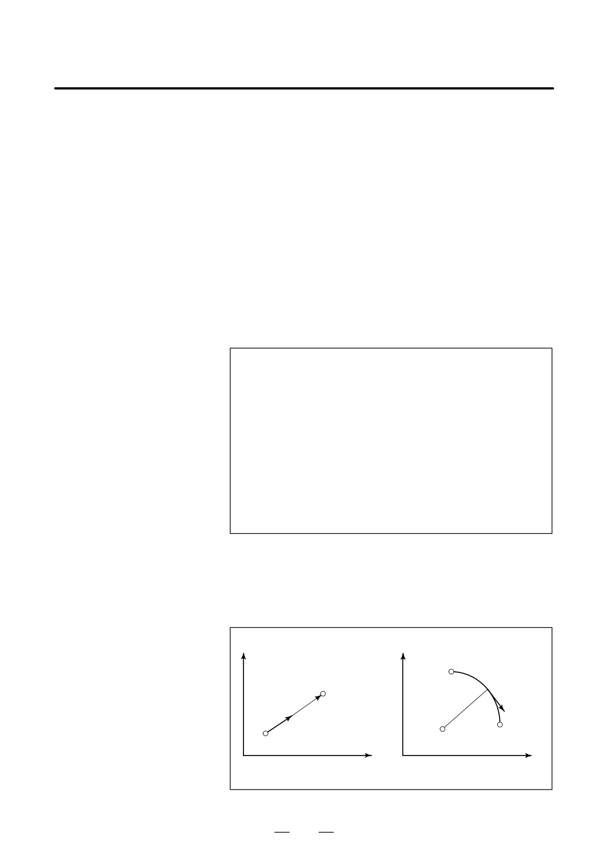
D Tangential speed
Cutting feed is controlled so that the tangential feedrate is always set at
constant control
a specified feedrate.
Y
Y
Starting
End point
point
F
F
Start
point
Center
End point
X
X
Linear interpolation
Circular interpolation
Fig. 5.3 (a) Tangential feedrate (F)
97
5. FEED FUNCTIONS
PROGRAMMING
B-63534EN/02
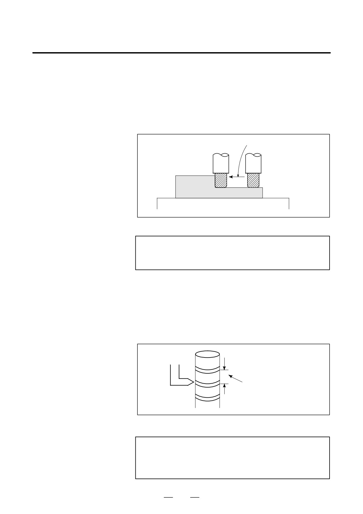
D Feed per minute (G94)
After specifying G94 (in the feed per minute mode), the amount of feed
of the tool per minute is to be directly specified by setting a number after
F. G94 is a modal code. Once a G94 is specified, it is valid until G95 (feed
per revolution) is specified. At power-on, the feed per minute mode is
set.
An override from 0% to 254% (in 1% steps) can be applied to feed per
minute with the switch on the machine operator’s panel. For detailed
information, see the appropriate manual of the machine tool builder.
Feed amount per minute
(mm/min or inch/min)
Tool
Workpiece
Table
Fig. 5.3 (b) Feed per minute
WARNING
No override can be used for some commands such as for
threading.
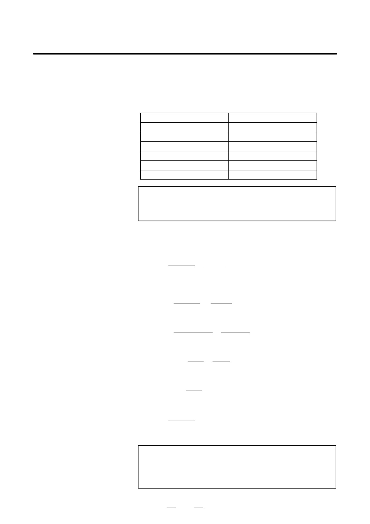
D Feed per revolution
After specifying G95 (in the feed per revolution mode), the amount of
(G95)
feed of the tool per spindle revolution is to be directly specified by setting
a number after F. G95 is a modal code. Once a G95 is specified, it is valid
until G94 (feed per minute) is specified.
An override from 0% to 254% (in 1% steps) can be applied to feed per
revolution with the switch on the machine operator’s panel. For detailed
information, see the appropriate manual of the machine tool builder.
F
Feed amount per spindle revolution
(mm/rev or inch/rev)
Fig. 5.3 (c) Feed per revolution
CAUTION
When the speed of the spindle is low, feedrate fluctuation
may occur. The slower the spindle rotates, the more
frequently feedrate fluctuation occurs.
98
B-63534EN/02
PROGRAMMING
5. FEED FUNCTIONS
D Inverse time feed (G93)
When G93 is specified, the inverse time specification mode (G93 mode)
is set. Specify the inverse time (FRN) with an F code.
A value from 0.001 to 9999.999 can be specified as FRN, regardless of
whether the input mode is inches or metric, or the increment system is
IS-B or IS-C.
F code specification value
FRN
F1
0.001
F1 *1
1.000
F1.0
1.000
F9999999
9999.999
F9999 *1
9999.000
F9999.999
9999.999
NOTE
*1
Value specified in fixed-point format with bit 0 (DPI) of parameter
No. 3401 set to 1
Explanations
For linear interpolation (G01)
1
feedrate
Feedrate:mm/min
(for metric input)
FRN=
=
time (min)
distance
inch/min(for inch input)
Distance:mm
(for metric input)
inch(for inch input)
- To end a block in 1 (min)
1
1
FRN =
=
= 1
Specify F1.0.
time (min)
1 (min)
- To end a block in 10 (sec)
1
1
FRN =
=
= 6
Specify F6.0.
time (sec) / 60
10/60 (sec)
- To find the movement time required when F0.5 is specified
1
1
Time
(min) =
=
= 2
2 (min) is required.
FRN
0.5
- To find the movement time required when F10.0 is specified
1
60
60
Time (sec) =
=
= 6
6 (sec) is required.
FRN
10
For circular interpolation (G01)
1
feedrate Feedrate: mm/min (for metric input)
FRN=
=
time (min) arc radius inch/min(for inch input)
Arc radius: mm (for metric input)
inch(for inch input)
NOTE
In the case of circular interpolation, the feedrate is
calculated notfrom the actual amount of movement in the
block but from the arcradius.
99