FANUC Series 16i/160i/160is-MB, Series 18i/180i/180is-MB5, Series 18i/180i/180is-MB. Operator's Manual - page 5

5. FEED FUNCTIONS
PROGRAMMING
B-63534EN/02
G93 is a modal G code and belongs to group 05 (includes G95 (feed per
revolution) and G94 (feed per minute)).
When an F value is specified in G93 mode and the feedrate exceeds the
maximum cutting feedrate, the feedrate is clamped to the maximum
cutting feedrate.
In the case of circular interpolation, the feedrate is calculated not from the
actual amount of movement in the block but from the arc radius. This
means that actual machining time is longer when the arc radius is longer
than the arc distance and shorter when the arc radius is shorter than the arc
distance. Inverse time feed can also be used for cutting feed in a canned
cycle.Notes
NOTE
1
In the G93 mode, an F code is not handled as a modal code and
therefore needs to be specified in each block. If an F code is not
specified, P/S alarm (No. 11 (indicating that cutting feedrate
specification is missing)) is issued.
2
When F0 is specified in G93 mode, P/S alarm (No. 11 (indicating
that cutting feedrate specification is missing)) is issued.
3
Inverse time feed cannot be used when PMC axis control is in
effect.
4
If the calculated cutting feedrate is smaller than the allowable
range, P/S alarm
(No.
11
(indicating that cutting feedrate
specification is missing)) is issued.
100
B-63534EN/02
PROGRAMMING
5. FEED FUNCTIONS
D One-digit F code feed
When a one-digit number from 1 to 9 is specified after F, the feedrate
set for that number in a parameter (Nos. 1451 to 1459) is used. When
F0 is specified, the rapid traverse rate is applied.
The feedrate corresponding to the number currently selected can be
increased or decreased by turning on the switch for changing F1-digit
feedrate on the machine operator’s panel, then by rotating the manual
pulse generator.
The increment/decrement, ∆F, in feedrate per scale of the manual pulse
generator is as follows:
∆F+Fmax
100X
Fmax : feedrate upper limit for F1-F4 set by parameter (No.1460), or
feedrate upper limit for F5-F9 set by parameter (No.1461)
X :any value of 1-127 set by parameter (No.1450)
The feedrate set or altered is kept even while the power is off. The current
feed rate is displayed on the CRT screen.
D Cutting feedrate clamp
A common upper limit can be set on the cutting feedrate along each axis
with parameter No. 1422. If an actual cutting feedrate (with an override
applied) exceeds a specified upper limit, it is clamped to the upper limit.
Parameter No. 1430 can be used to specify the maximum cutting feedrate
for each axis only for linear interpolation and circular interpolation.
When the cutting feedrate along an axis exceeds the maximum feedrate
for the axis as a result of interpolation, the cutting feedrate is clamped to
the maximum feedrate.
NOTE
An upper limit is set in mm/min or inch/min. CNC calculation
may involve a feedrate error of ±2% with respect to a
specified value. However, this is not true for
acceleration/deceleration. To be more specific, this error is
calculated with respect to a measurement on the time the
tool takes to move 500 mm or more during the steady state:
Reference
See Appendix C for range of feedrate command value.
101
5. FEED FUNCTIONS
PROGRAMMING
B-63534EN/02
Cutting feedrate can be controlled, as indicated in Table 5.4 (a).
5.4
CUTTING FEEDRATE
CONTROL
Table 5.4 (a) Cutting Feedrate Control
Function name
G code
Validity of G code
Description
The tool is decelerated at the end point
This function is valid for specified
Exact stop
G09
of a block, then an in-position check is
blocks only.
made. Then the next block is executed.
Once specified, this function is
The tool is decelerated at the end point
Exact stop mode
G61
valid until G62, G63, or G64 is
of a block, then an in-position check is
specified.
made. Then the next block is executed.
Once specified, this function is
The tool is not decelerated at the end
Cutting mode
G64
valid until G61, G62, or G63 is
point of a block, but the next block is
specified.
executed.
The tool is not decelerated at the end
Once specified, this function is
point of a block, but the next block is
Tapping mode
G63
valid until G61, G62, or G64 is
executed.
specified.
When G63 is specified, feedrate override
and feed hold are invalid.
When the tool moves along an inner
corner during cutter compensation, over-
Once specified, this function is
Automatic override for
ride is applied to the cutting feedrate to
G62
valid until G61, G63, or G64 is
inner corners
suppress the amount of cutting per unit
specified.
Auto-
of time so that a good surface finish can
matic
be produced.
This function is valid in the cutter
Internal circular cutting
The internal circular cutting feedrate is
_
compensation mode, regardless of
feedrate change
changed.
the G code.
NOTE
1
The purpose of in-position check is to check that the servo
motor has reached within a specified range (specified with
a parameter by the machine tool builder).
In-position check is not performed when bit 5 (NCI) of
parameter No. 1601 is set to 1.
2
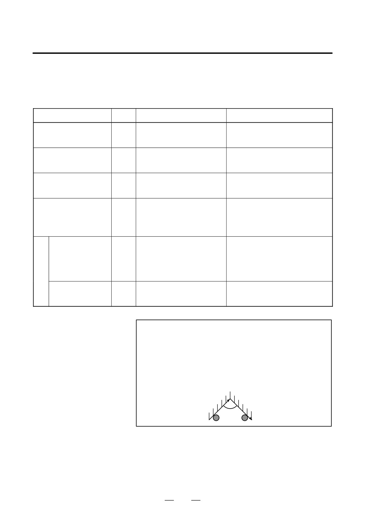
Inner corner angle θ: 2°< θ x α x 178°
(α is a set value)
Workpiece
θ
Tool
102
B-63534EN/02
PROGRAMMING
5. FEED FUNCTIONS
Format
Exact stop
G09 IP_ ;
Exact stop mode
G61 ;
Cutting mode
G64 ;
Tapping mode
G63 ;
Automatic corner override G62 ;
5.4.1
Exact Stop (G09, G61)
Cutting Mode (G64)
Tapping Mode (G63)
Explanations
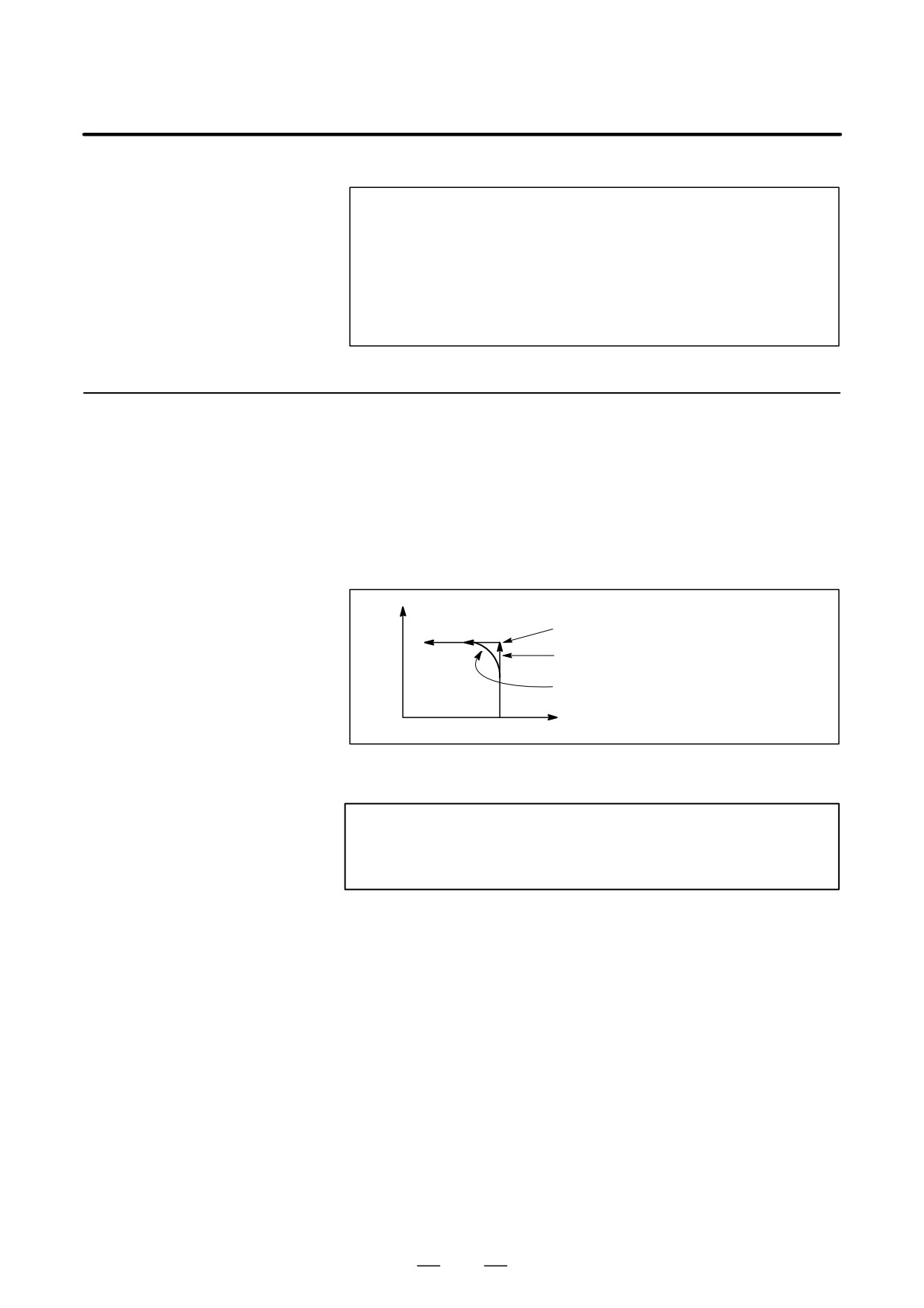
The inter-block paths followed by the tool in the exact stop mode, cutting
mode, and tapping mode are different (Fig. 5.4.1 (a)).
Y
Position check
(2)
Tool path in the exact stop mode
(1)
Tool path in the cutting mode or
tapping mode
0
X
Fig. 5.4.1 (a) Example of Tool Paths from Block (1) to Block (2)
CAUTION
The cutting mode (G64 mode) is set at power-on or system
clear.
103
5. FEED FUNCTIONS
PROGRAMMING
B-63534EN/02
5.4.2
When cutter compensation is performed, the movement of the tool is
automatically decelerated at an inner corner and internal circular area.
Automatic Corner
This reduces the load on the cutter and produces a smoothly machined
Override
surface.
5.4.2.1
Automatic Override for
Inner Corners (G62)
Explanations
D Override condition
When G62 is specified, and the tool path with cutter compensation
applied forms an inner corner, the feedrate is automatically overridden
at both ends of the corner.
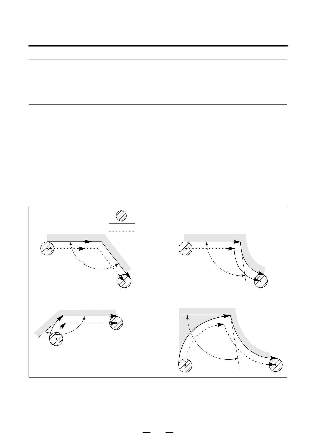
There are four types of inner corners (Fig. 5.4.2.1 (a)).
2,xθxθpx178, in Fig. 5.4.2.1 (a)
θp is a value set with parameter No. 1711. When θ is approximately
equal to θp, the inner corner is determined with an error of 0.001,or
less.
1. Straight line-straight line
:Tool
2. Straight line-arc
:Programmed path
:Cutter center path
θ
θ
3. Arc-straight line
4. Arc-arc
θ
θ
Fig. 5.4.2.1 (a) Inner corner
104
B-63534EN/02
PROGRAMMING
5. FEED FUNCTIONS
Override range
When a corner is determined to be an inner corner, the feedrate is
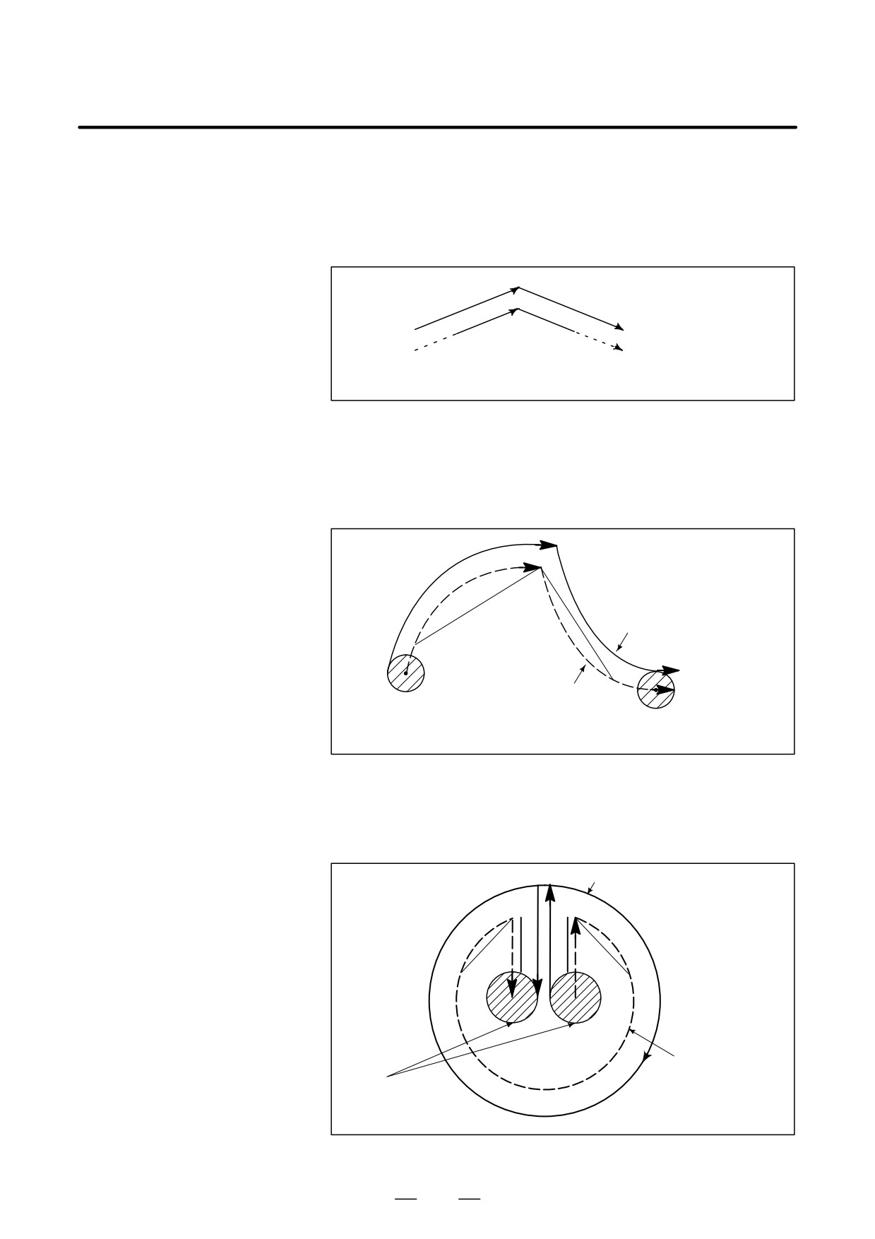
overridden before and after the inner corner. The distances Ls and Le,
where the feedrate is overridden, are distances from points on the cutter
center path to the corner (Fig. 5.4.2.1 (b), Fig. 5.4.2.1 (c), Fig. 5.4.2.1 (d)).
Ls and Le are set with parameter Nos. 1713 and 1714.
Programmed path
Le
Ls
b
a
Cutter center path
The feedrate is overridden from point a to point b.
FIg. 5.4.2.1 (b) Override Range (Straight Line to Straight Line)
When a programmed path consists of two arcs, the feedrate is overridden
if the start and end points are in the same quadrant or in adjacent quadrants
(Fig. 5.4.2.1 (c)).
Le
Programmed path
Ls
a
b
Cutter center path
The feedrate is overridden from point a to b.
Fig. 5.4.2.1 (c) Override Range (Arc to Arc)
Regarding program (2) of an arc, the feedrate is overridden from point a
to point b and from point c to point d (Fig. 5.4.2.1 (d)).
Programmed path
d
a
Le
Ls
Le
Ls
c
b
(2)
Cutter center path
Tool
Fig. 5.4.2.1 (d) Override Range (Straight Line to Arc, Arc to Straight Line)
105
5. FEED FUNCTIONS
PROGRAMMING
B-63534EN/02
Override value
An override value is set with parameter No. 1712. An override value is
valid even for dry run and F1-digit specification.
In the feed per minute mode, the actual feedrate is as follows:
F × (automatic override for inner corners) × (feedrate override)
Limitations
D Acceleration/deceleratio
Override for inner corners is disabled during acceleration/deceleration
n before interpolation
before interpolation.
D Start-up/G41, G42
Override for inner corners is disabled if the corner is preceded by a
start-up block or followed by a block including G41 or G42.
D Offset
Override for inner corners is not performed if the offset is zero.
5.4.2.2
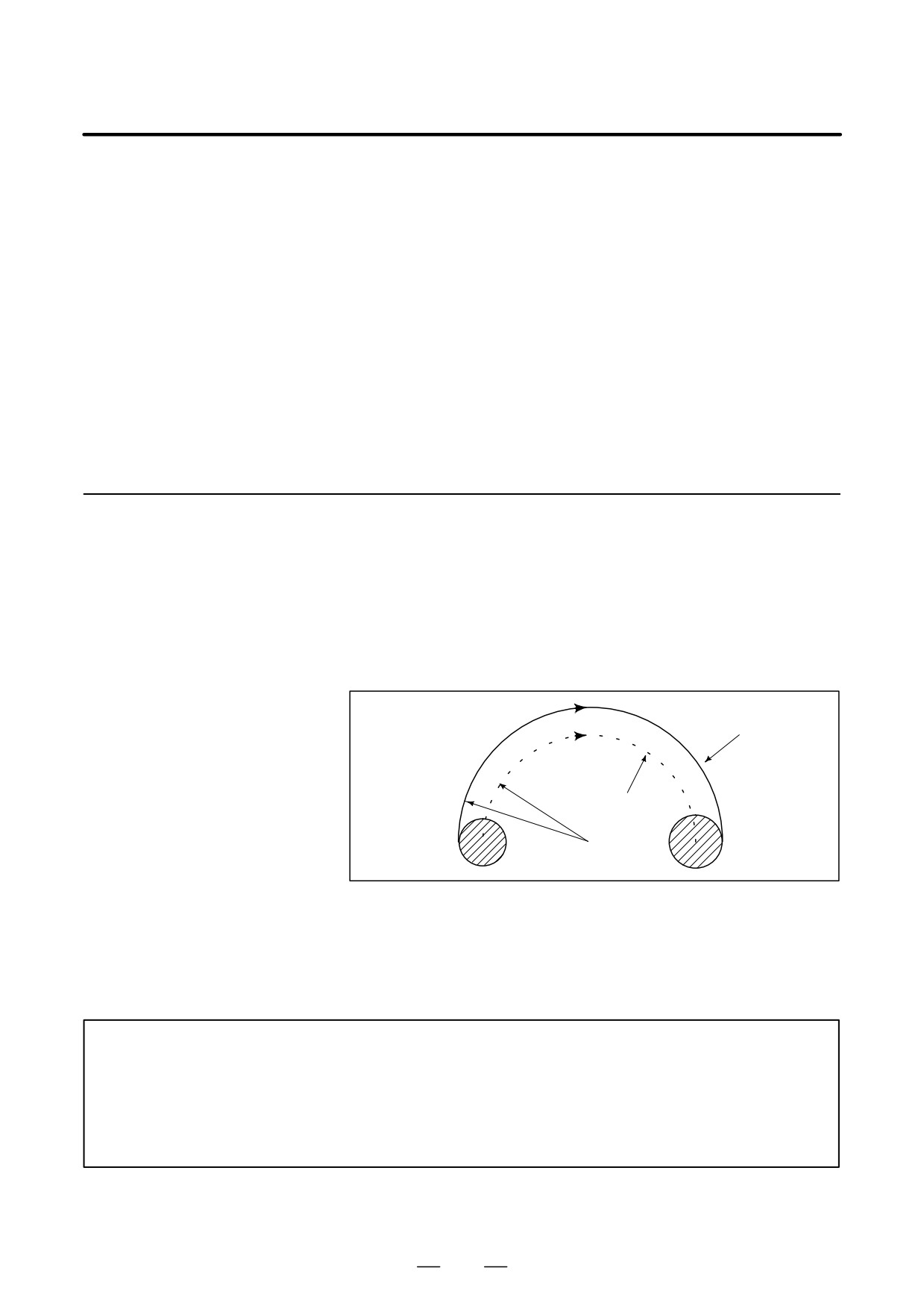
For internally offset circular cutting, the feedrate on a programmed path
is set to a specified feedrate (F) by specifying the circular cutting feedrate
Internal Circular Cutting
with respect to F, as indicated below (Fig. 5.4.2.2). This function is valid
Feedrate Change
in the cutter compensation mode, regardless of the G62 code.
Rc
F
Rp
Rc : Cutter center path radius
Rp : Programmed radius
It is also valid for the dry run and the one-digit F command.
Programmed path
Rc Cutter center
path
Rp
Fig. 5.4.2.2 Internal circular cutting feedrate change
If Rc is much smaller than Rp, Rc/Rp80; the tool stops. A minimum
deceleration ratio (MDR) is to be specified with parameter No. 1710.
When Rc/RpxMDR, the feedrate of the tool is (F×MDR).
NOTE
When internal circular cutting must be performed together with override for inner corners, the
feedrate of the tool is as follows:
Rc
F
(override for the inner corners)×(feedrate override)
Rp
106
B-63534EN/02
PROGRAMMING
5. FEED FUNCTIONS
5.4.3
This function automatically controls the feedrate at a corner according to
the corner angle between the machining blocks or the feedrate difference
Automatic Corner
between the blocks along each axis.
Deceleration
This function is effective when ACD, bit 6 of parameter No. 1601, is set
to 1, the system is in G64 mode (machining mode), and a cutting-feed
block (block A) is followed by another cutting-feed block (block B).
The feedrate between machining blocks is controlled according to the
corner angle between the blocks or the feedrate difference between the
blocks along each axis. These two methods can be switched with CSD,
bit 4 of parameter No. 1602.
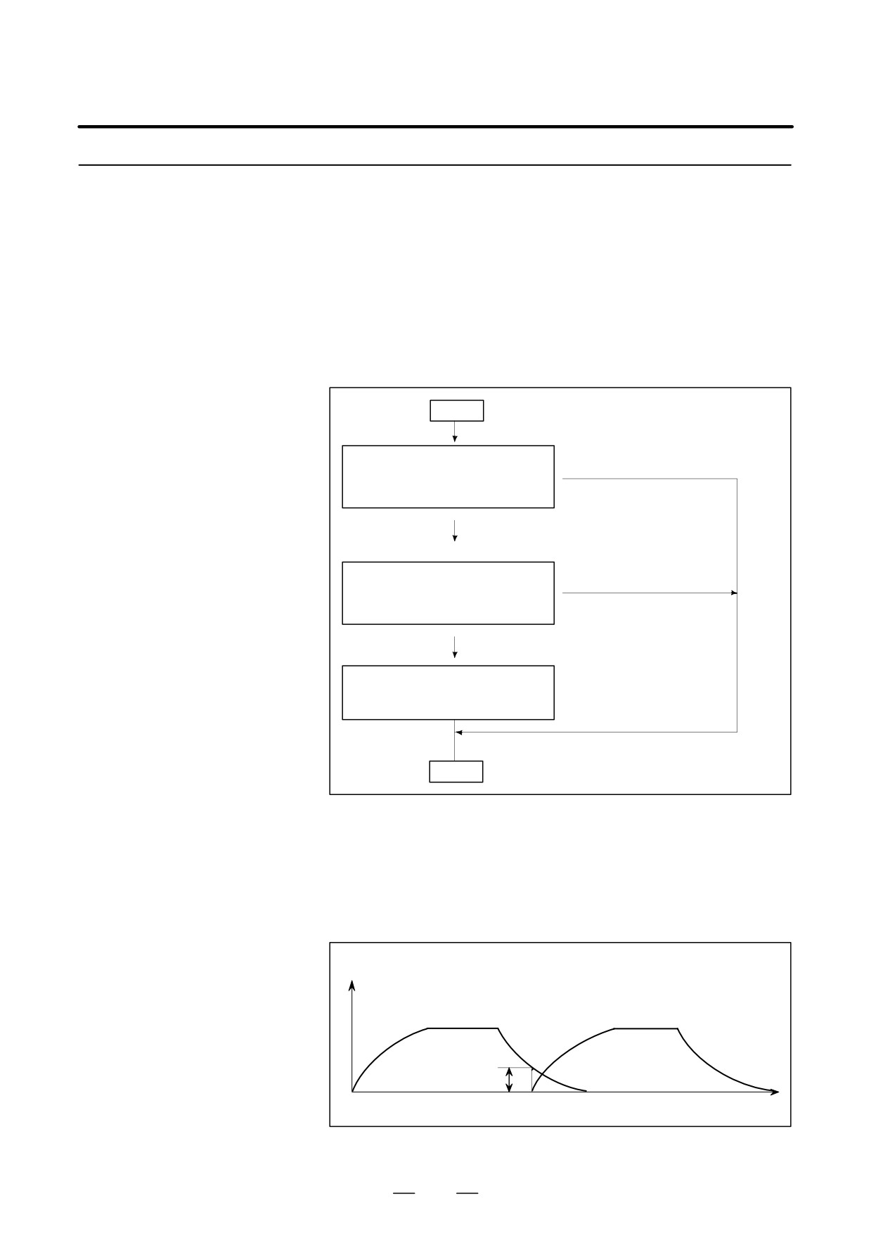
5.4.3.1
This function decelerates the feedrate when the angle between blocks A
and B on the selected plane is smaller than the angle specified in parameter
Corner Deceleration
No. 1740. The function executes block B when the feedrates along both
According to the Corner
the first and second axes are smaller than the feedrate specified in
Angle
parameter No. 1741. In this case, the function determines that the number
of accumulated pulses is zero.
Explanations
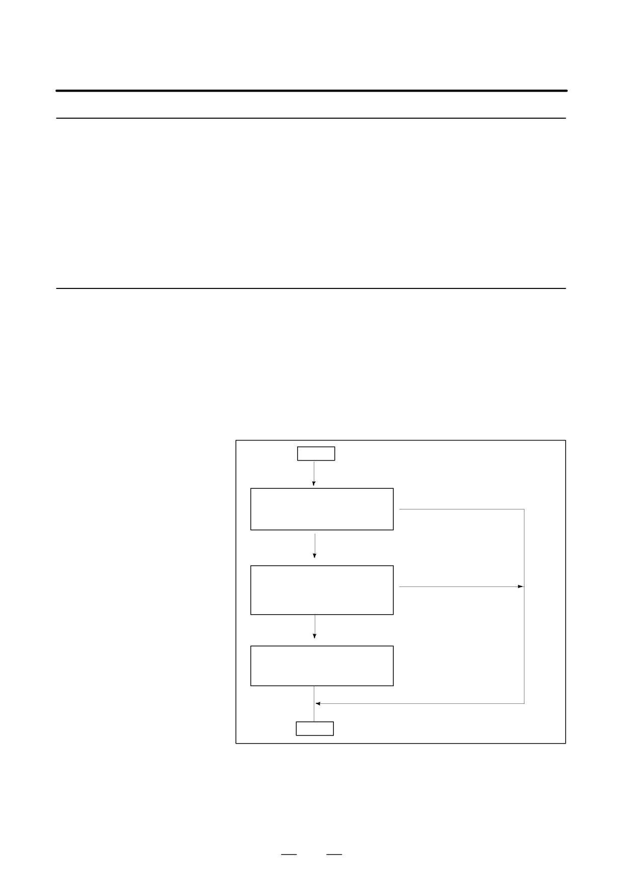
D Flowchart for feedrate
The flowchart for feedrate control is shown below.
control
START
Is the corner angle smaller than
No
the angle
specified in parameter
(No. 1740)?
Yes
Are the feedrates along the X-
No
and Y-axes smaller than that
specified in parameter
Further decelerates the
(No. 1741)?
feedrate in block A
Yes
The number of accumulated
pulses is
determined to be zero
and block B is executed
END
107
5. FEED FUNCTIONS
PROGRAMMING
B-63534EN/02
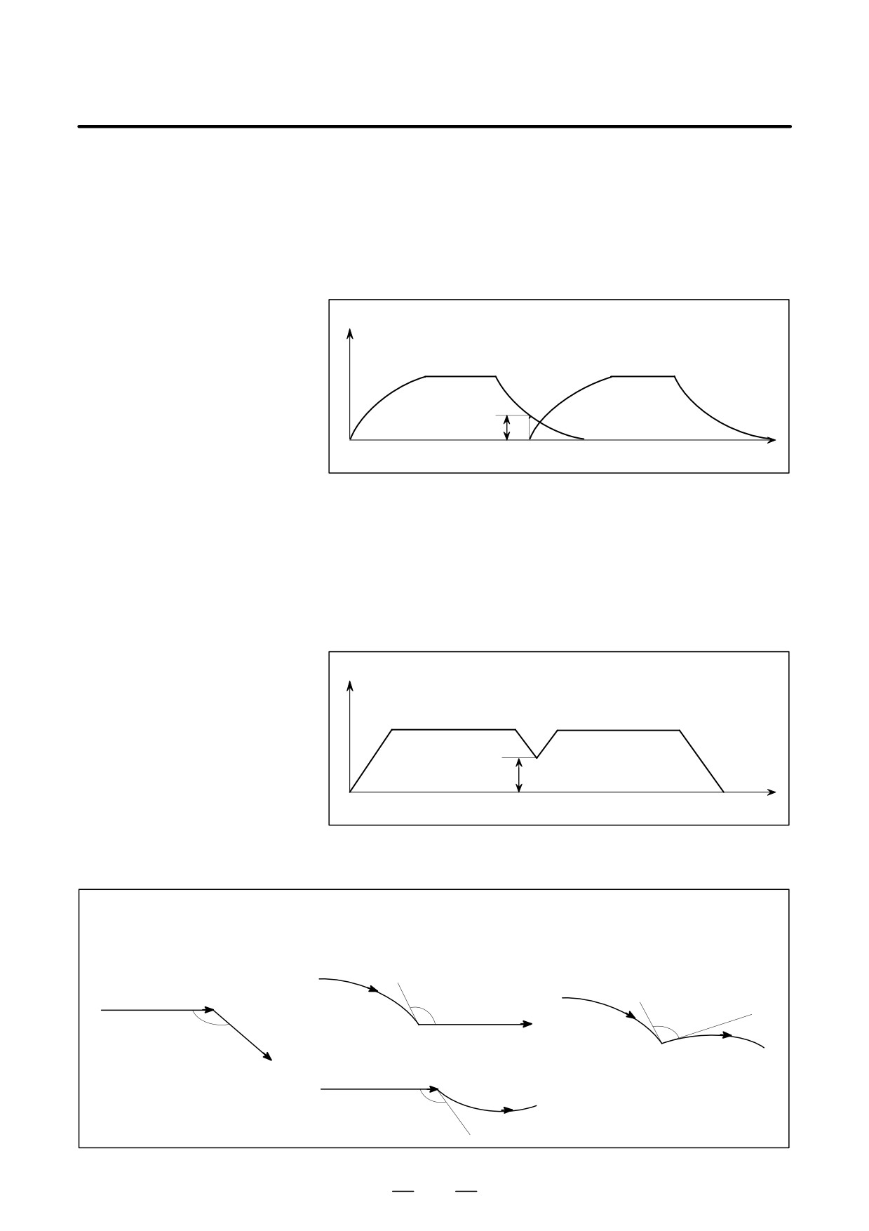
D Feedrate and time
When the corner angle is smaller than the angle specified in the
parameter, the relationship between the feedrate and time is as shown
below. Although accumulated pulses equivalent to the hatched area
remain at time t, the next block is executed because the feedrate of the
automatic acceleration/deceleration circuit is smaller than the
parameter-set value. This function is effective only for movement on
the selected plane.
Feedrate V
Block A
Block B
ÍÍ
Parameter-set feedrate
t
Time t
D Acceleration/
When acceleration/deceleration before interpolation is effective, the
deceleration before
relationship between the feedrate and time is as shown below. When the
interpolation
angle between blocks A and B on the selected plane is smaller than the
angle specified in parameter (No. 1740), and the feedrates specified in
blocks A and B are larger than that specified in parameter (No. 1777), the
feedrate is decelerated to the parameter-set value in block A, and
accelerated to the feedrate specified in block B. The acceleration depends
on the parameter for acceleration/deceleration before interpolation.
Feedrate
Block A
Block B
Parameter-set feedrate
(parameter No. 1777)
Time
D Angle between two
The angle between two blocks (blocks A and B) is assumed to be angle
blocks
θ, as shown below.
1. Between linear movements
2. Between linear and circular movements
3. Between circular movements
(angle between the linear movement
(angle between the tangents to
and tangent to the circular movement)
the circular movements)
θ
θ
θ
θ
108
B-63534EN/02
PROGRAMMING
5. FEED FUNCTIONS
D Selected plane
The machining angle is compared with the angle specified in parameter
(No. 1740) for movements on the selected plane only. Machining
feedrates are compared with that specified in parameter (No. 1741) for
movement along the first and second axes on the selected plane only. This
means, when movement occurs along three or more axes, only that
movement along the first and second axes on the selected plane is
considered.
D Corner roundness
Corner roundness is determined by the angle and feedrate specified in
parameter (Nos. 1740 and 1741). To always make a sharp corner, set
the angle to zero and the feedrate to 180000 (equivalent to 180
degrees).
D Exact stop
When G90 (exact stop) is specified, exact stop is performed irrespective
of the angle and feedrate specified in parameter (Nos. 1740 and 1741).
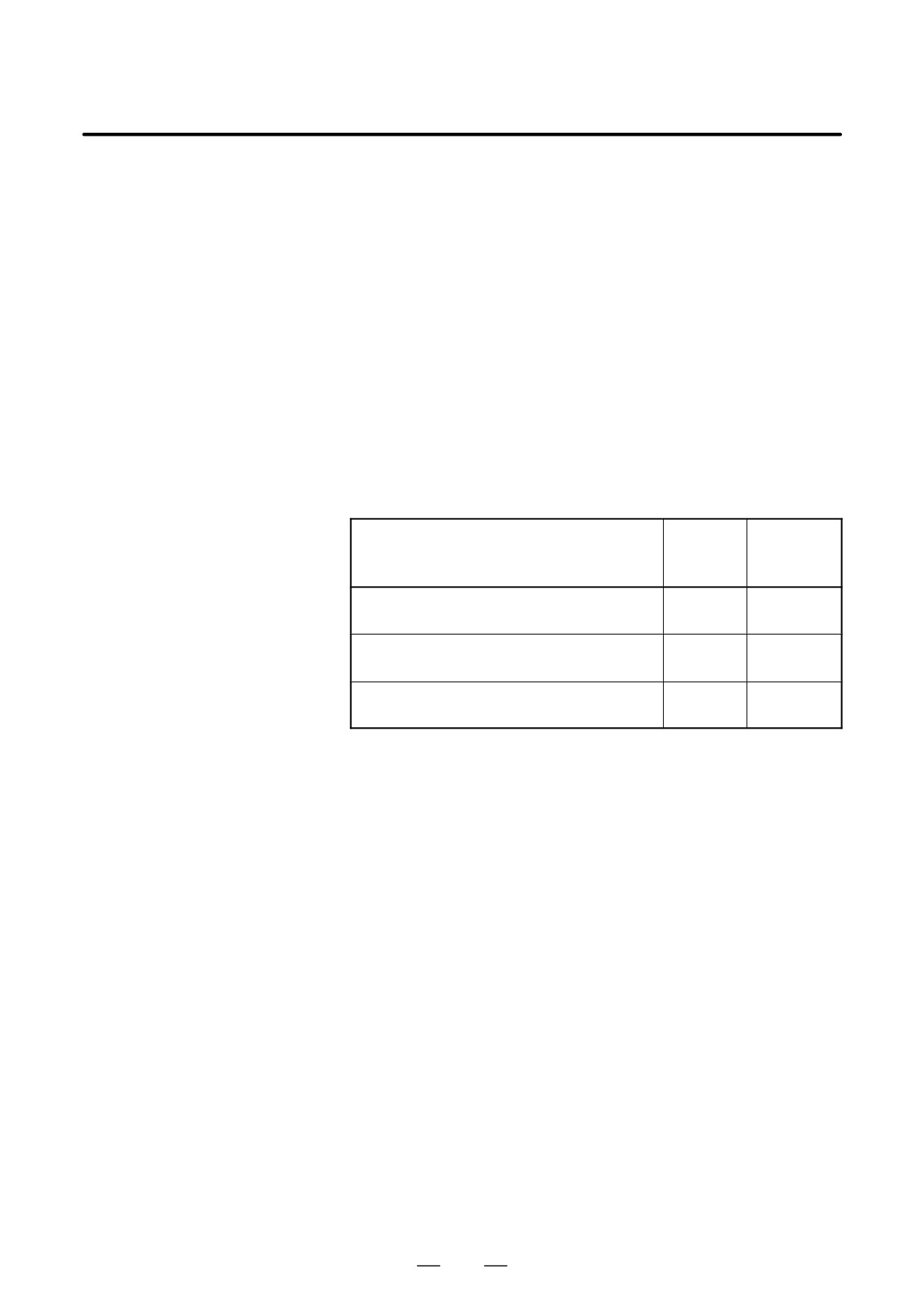
D Look-ahead control
Those parameters related to automatic corner deceleration in look-ahead
control mode are shown below.
Look-ahead
Normal
Parameter description
control
mode
mode
Switching the methods for automatic corner de-
No.1602#4
←
celeration
Lower limit of feedrate in automatic corner decel-
No.1777
No.1778
eration based on the angle
Limit angle in corner deceleration based on the
No.1740
No.1779
angle
Limitations
This function cannot be enabled for a single block or during dry run.
109
5. FEED FUNCTIONS
PROGRAMMING
B-63534EN/02
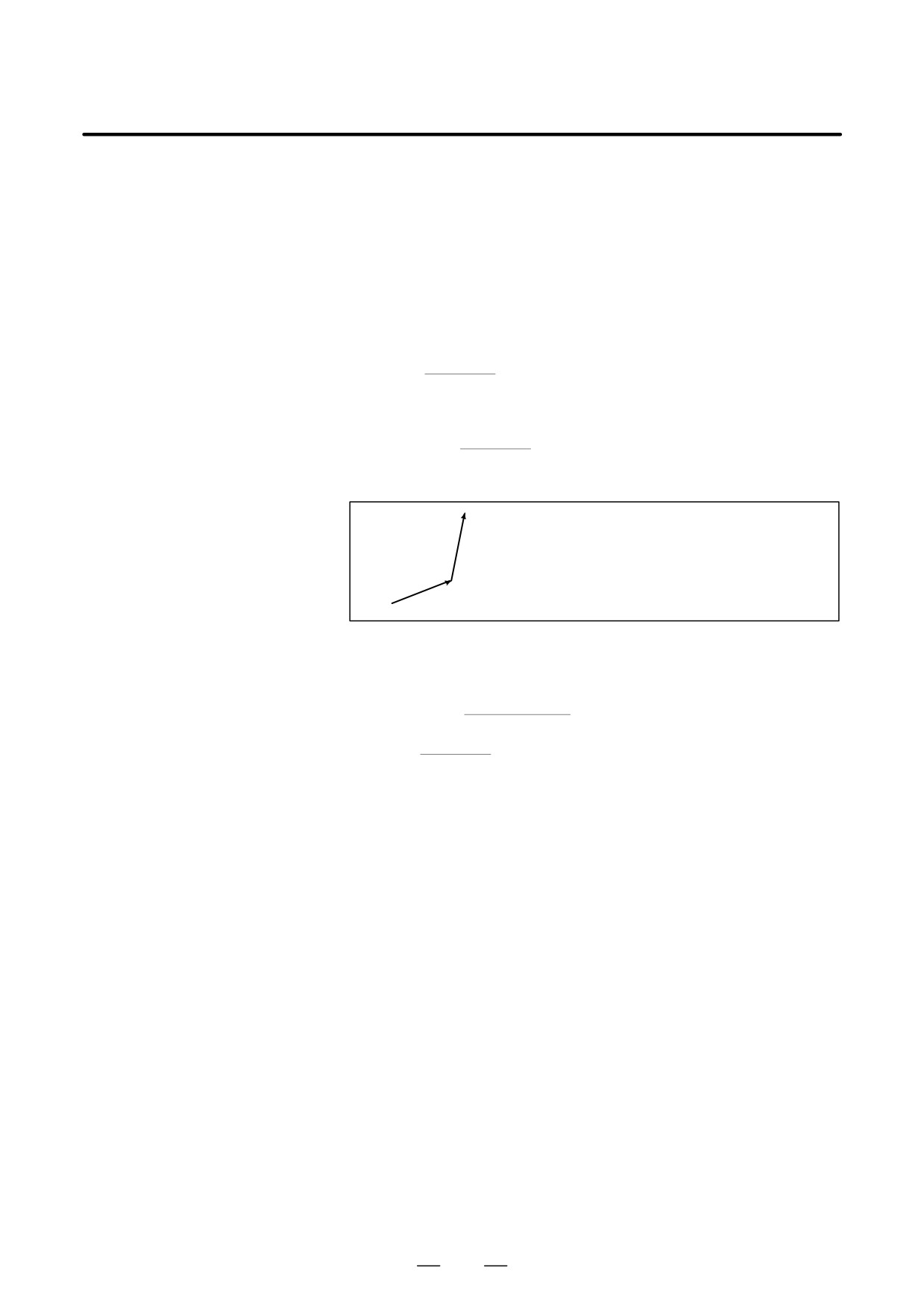
5.4.3.2
This function decelerates the feedrate when the difference between the
feedrates at the end point of block A and the start point of block B along
Corner Deceleration
each axis is larger than the value specified in parameter No. 1781. The
According to the
function executes block B when the feedrates along all axes are smaller
Feedrate Difference
than the feedrate specified in parameter No. 1741. In this case, the
between Blocks Along
function determines that the number of accumulated pulses is zero.
Each Axis
Explanations
D Flowchart for feedrate
The flowchart for feedrate control is shown below.
control
START
Is the feedrate difference between
No
blocks along each axis larger than
the value specified in parameter
(No. 1781)?
Yes
Are the feedrates along all axes
No
smaller than that specified in
parameter (No. 1741)?
Further decelerates the
feedrate in block A
Yes
The number of accumulated pulses
is determined
to be zero and block
B is executed.
END
D Feedrate and time
When the feedrate difference between blocks along each axis is larger than
the value specified in parameter No. 1781, the relationship between the
feedrate and time is as shown below. Although accumulated pulses
equivalent to the hatched area remain at time t, the next block is executed
because the feedrate of the automatic acceleration/deceleration circuit is
smaller than the feedrate specified in parameter No. 1741.
Feedrate V
Block A
Block B
Parameter-set feedrate
ÍÍ
t
Time t
110
B-63534EN/02
PROGRAMMING
5. FEED FUNCTIONS
D Acceleration /
When acceleration/deceleration before interpolation is effective, the
deceleration before
relationship between the feedrate and time is as described below.
interpolation
When the feedrate difference between blocks A and B along each axis is
larger than the value specified in parameter No. 1780, the feedrate is
decelerated to the corner feedrate calculated from the feedrate difference
along each axis.
Let the feedrate be F. Compare the feedrate difference along each axis
(Vc[X], Vc[Y], ...) with the value specified in parameter No. 1780, Vmax.
When the difference exceeds Vmax, calculate R as shown below.
Vc
R=
Vmax
Find the maximum value for R among the calculated values for the axes.
Let it be Rmax. Then, the corner feedrate can be obtained as follows:
1
Fc=F
Rmax
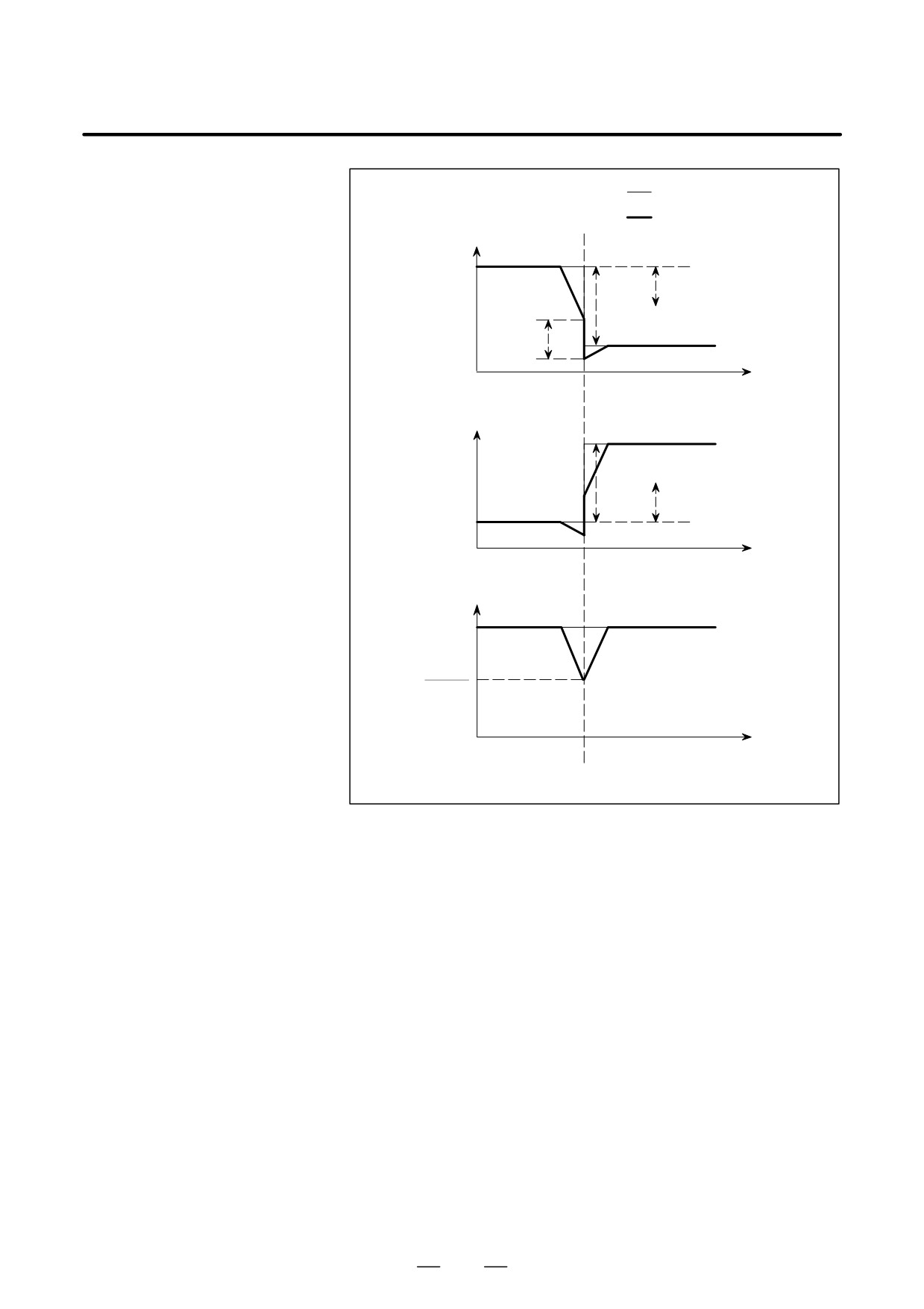
(Example)
N2
N1 G01 G91 X80. Y20. F3000 ;
N2 X20. Y80. ;
N1
When this movement is specified, the feedrate along each axis is as
shown in the next figure.
Vc [X(Y)]
Rmax=
Vmax
1
F
Rmax
From the figure, it can be seen that the feedrate differences along the X-
and Y-axes (Vc[X] and Vc[Y]) exceed Vmax. Calculate Rmax to get
Fc. When the feedrate is decelerated to Fc at the corner, the feedrate
difference along each axis do not exceed Vmax.
111
5. FEED FUNCTIONS
PROGRAMMING
B-63534EN/02
Without corner deceleration
With corner deceleration
Feedrate along
Vc [X]
Vmax
the X-axis
Vmax
Feedrate along
the Y-axis
Vc [Y]
Vmax
Feedrate along
the tangent
at the corner
1
F
Rmax
N1
N2
t
D Setting the allowable
The allowable feedrate difference can be specified for each axis in
feedrate difference along
parameter No. 1783.
each axis
D Checking the feedrate
The feedrate difference is also checked during dry-run operation or
difference
during deceleration caused by an external signal, using feedrate
commands specified in a program.
D Exact stop
When G90 (exact stop) is specified, exact stop is performed irrespective
of the parameter settings.
D Override
If an override is changed during operation, the feedrate difference will
not be checked correctly.
112
B-63534EN/02
PROGRAMMING
5. FEED FUNCTIONS
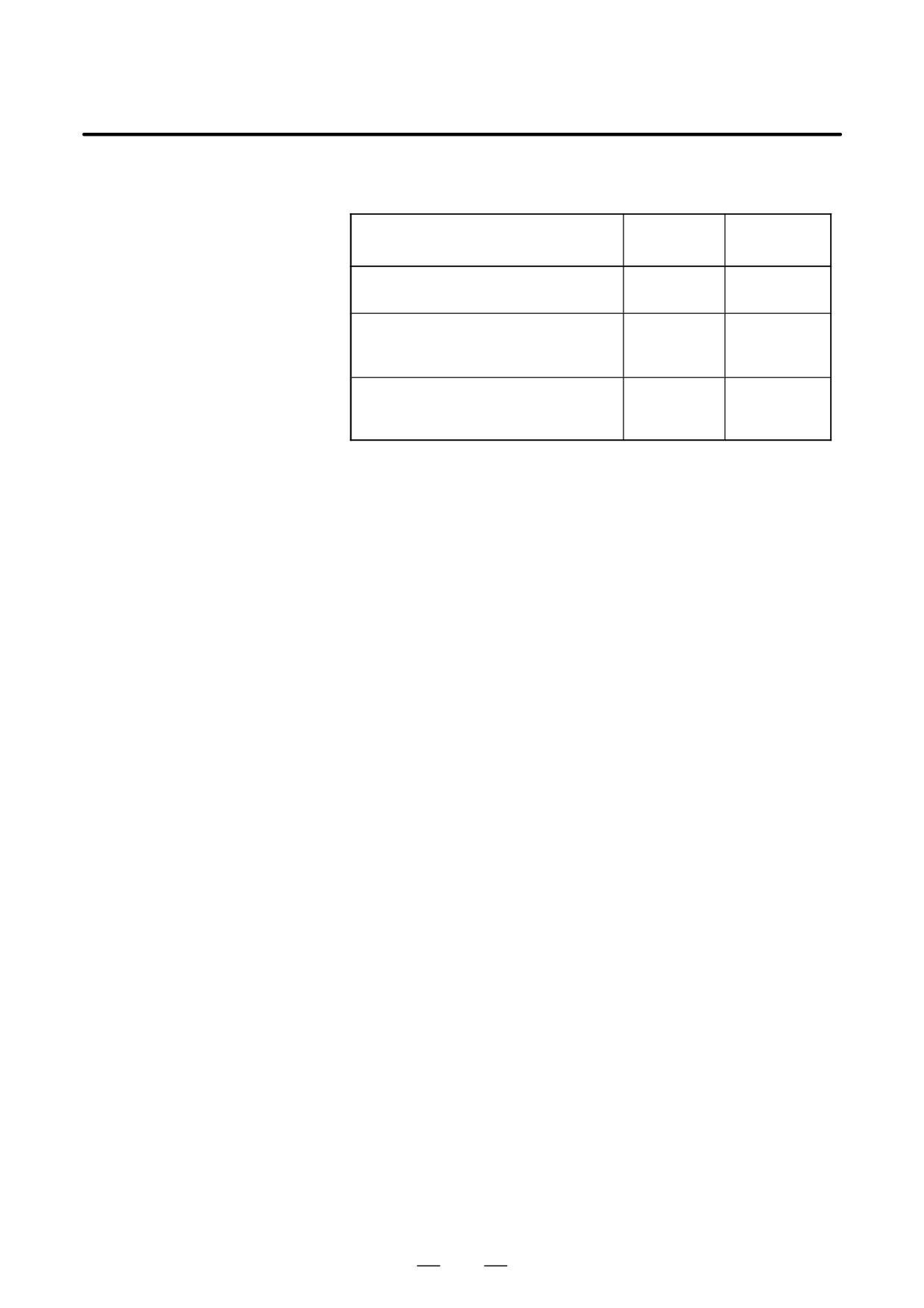
D Look-ahead control
Parameters related to automatic corner deceleration in look-ahead
control mode are shown below.
Normal
Look-ahead
Parameter description
mode
control mode
Switching the methods for automatic corner
No.1602#4
No.1602#4
deceleration
Allowable feedrate difference (for all axis) in
automatic corner deceleration based on the
No.1780
No.1780
feedrate difference
Allowable feedrate difference
(for each
axis) in automatic corner deceleration
No.1783
No.1783
based on the feedrate difference
Limitations
This function is not effective for feed-per-rotation commands,
address-F-with-one-digit commands, rigid tapping, and a single block.
113
5. FEED FUNCTIONS
PROGRAMMING
B-63534EN/02
5.5
DWELL (G04)
Format
Dwell G04 X_ ; or G04 P_ ;
X_ : Specify a time or spindle speed (decimal point permitted)
P_ : Specify a time or spindle speed (decimal point not permitted)
Explanations
By specifying a dwell, the execution of the next block is delayed by the
specified time. In addition, a dwell can be specified to make an exact
check in the cutting mode (G64 mode).
When neither P nor X is specified, exact stop is performed.
Bit 1 (DWL) of parameter No. 3405 can specify dwell for each rotation
in feed per rotation mode (G95).
Table 5.5 (a) Command value range of the dwell time
(Command by X)
Increment system
Command value range
Dwell time unit
IS-B
0.001 to 99999.999
s or rev
IS-C
0.0001 to 9999.9999
Table 5.5 (b) Command value range of the dwell time
(Command by P)
Increment system
Command value range
Dwell time unit
IS-B
1 to 99999999
0.001 s or rev
IS-C
1 to 99999999
0.0001 s or rev
114
PROGRAMMING
6. REFERENCE POSITION
B-63534EN/02
REFERENCE POSITION
6
A CNC machine tool has a special position where, generally, the tool is
exchanged or the coordinate system is set, as described later. This
position is referred to as a reference position.
115
6. REFERENCE POSITION
PROGRAMMING
B-63534EN/02
6.1
REFERENCE
POSITION RETURN
General
D Reference position
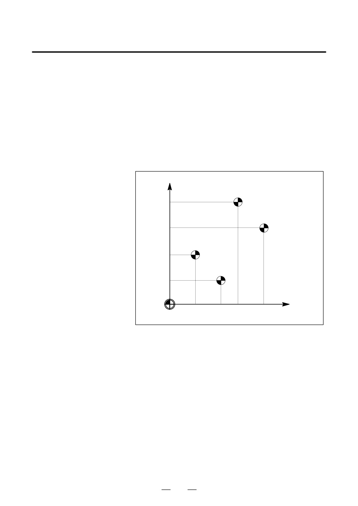
The reference position is a fixed position on a machine tool to which the
tool can easily be moved by the reference position return function.
For example, the reference position is used as a position at which tools
are automatically changed. Up to four reference positions can be
specified by setting coordinates in the machine coordinate system in
parameters (No. 1240 to 1243).
Y
2nd reference position
3rd reference position
Reference position
4th reference
position
X
Machine zero point
Fig. 6.1 (a) Machine zero point and reference positions
116
PROGRAMMING
6. REFERENCE POSITION
B-63534EN/02
D Reference position
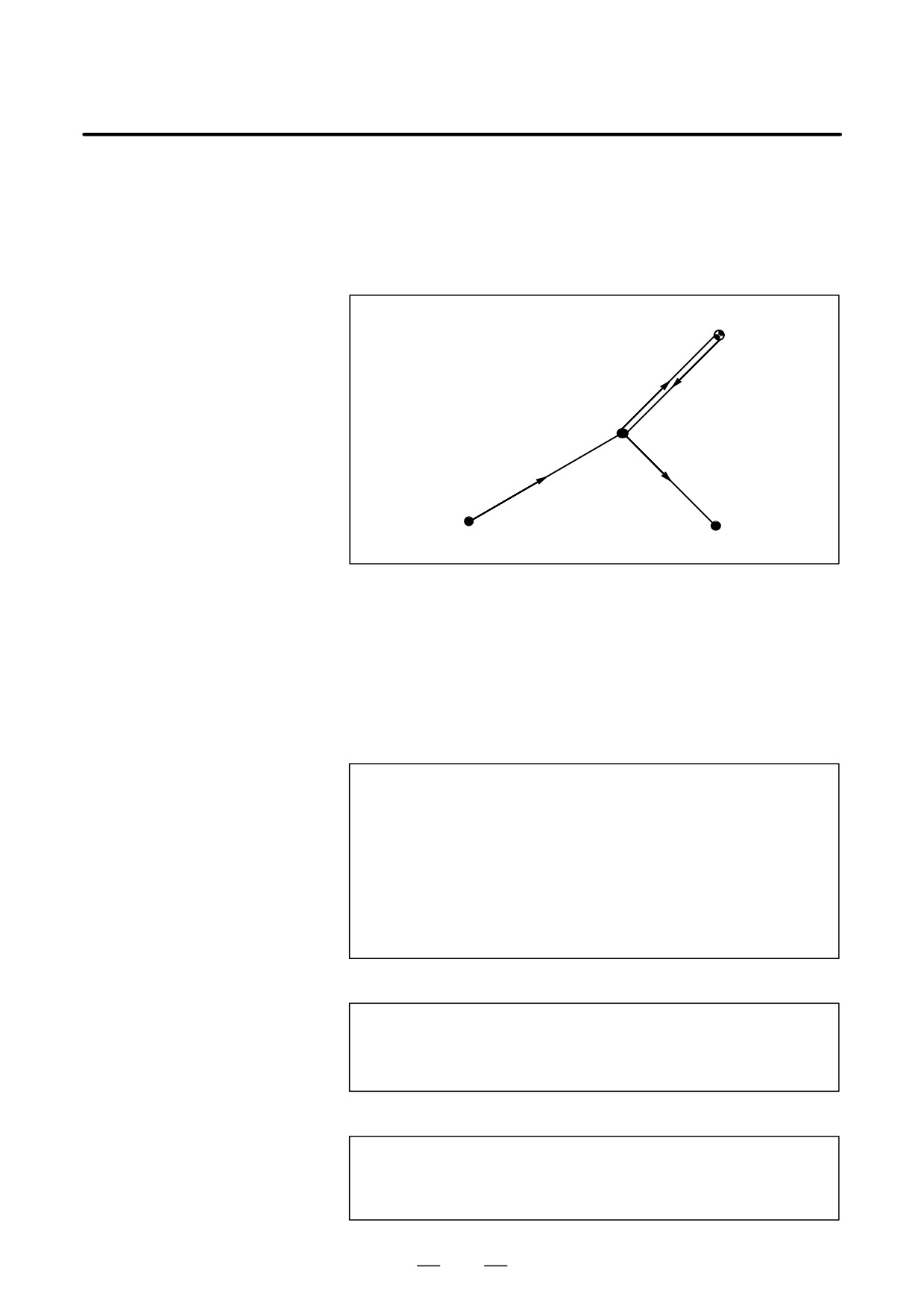
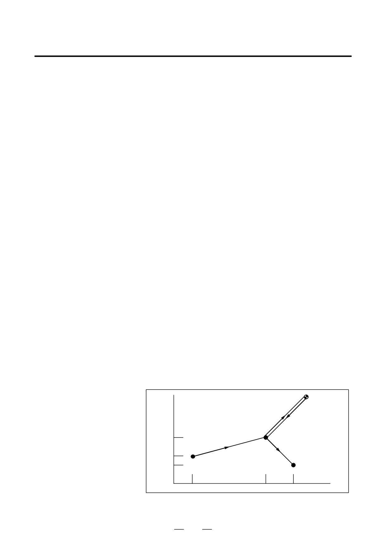
Tools are automatically moved to the reference position via an
return and movement
intermediate position along a specified axis. Or, tools are automatically
from the reference
moved from the reference position to a specified position via an
position
intermediate position along a specified axis. When reference position
return is completed, the lamp for indicating the completion of return goes
on.
Reference position return A→B→R
Return from the reference positionR→B→C
R (Reference position)
B (Intermediate
position)
A (Start position for
C (Destination of return from the
reference position return)
reference position)
Fig. 6.1 (b) Reference position return and return form the reference
position
D Reference position
The reference position return check (G27) is the function which checks
return check
whether the tool has correctly returned to the reference position as
specified in the program. If the tool has correctly returned to the reference
position along a specified axis, the lamp for the axis goes on.
Format
D Reference position
return
G28 IP_ ; Reference position return
(P2 can
G30 P2
IP
_;
2nd reference position return
be omitted.)
G30 P3IP
_ ; 3rd reference position return
G30 P4
IP
_;
4th reference position return
I
: Command specifying the intermediate position
(Absolute/incremental command)
D Return from reference
position
G29
_;
IP
I
: Command specifying the destination of return from reference
position (Absolute/incremental command)
D Reference position
return check
G27
_;
IP
I
: Command specifying the reference position
(Absolute/incremental command)
117
6. REFERENCE POSITION
PROGRAMMING
B-63534EN/02
Explanations
D Reference position
Positioning to the intermediate or reference positions are performed at the
return (G28)
rapid traverse rate of each axis.
Therefore, for safety, the cutter compensation, and tool length
compensation should be cancelled before executing this command.
The coordinates for the intermediate position are stored in the CNC only
for the axes for which a value is specified in a G28 block. For the other
axes, the previously specified coordinates are used.
Example N1 G28 X40.0 ; Intermediate position (X40.0)
N2 G28 Y60.0 ; Intermediate position (X40.0, Y60.0)
D
2nd, 3rd, and 4th
In a system without an absolute-position detector, the first, third, and
reference position return
fourth reference position return functions can be used only after the
(G30)
reference position return (G28) or manual reference position return (see
III-3.1) is made. The G30 command is generally used when the automatic
tool changer (ATC) position differs from the reference position.
D Return from the
In general, it is commanded immediately following the G28 command or
reference position (G29)
G30. For incremental programming, the command value specifies the
incremental value from the intermediate point.
Positioning to the intermediate or reference points are performed at the
rapid traverse rate of each axis.
When the workpiece coordinate system is changed after the tool reaches
the reference position through the intermediate point by the G28
command, the intermediate point also shifts to a new coordinate system.
If G29 is then commanded, the tool moves to to the commanded position
through the intermediate point which has been shifted to the new
coordinate system.
The same operations are performed also for G30 commands.
D Reference position
G27 command positions the tool at rapid traverse rate. If the tool reaches
return check (G27)
the reference position, the reference position return lamp lights up.
However, if the position reached by the tool is not the reference position,
an alarm (No. 092) is displayed.
D Setting of the reference
Before a machine coordinate system is established with the first reference
position return feedrate
position return after power-on, the manual and automatic reference
position return feedrates and automatic rapid traverse rate conform to the
setting of parameter No. 1428 for each axis. Even after a machine
coordinate system is established lupon the completion of reference
position return, the manual reference postiion return feedrate conforms to
the setting of the parameter.
118
PROGRAMMING
6. REFERENCE POSITION
B-63534EN/02
NOTE
1
To this feedrate, a rapid traverse override (F0 ,25,50,100%)
is applied, for which the setting is 100%.
2
After a machine coordinate system has been established
upon the completion of reference position return, the
automatic reference position return feedrate will conform to
the ordinary rapid traverse rate.
3
For the manual rapid traverse rate used before a machine
coordinate system is estavlished upon the completion of
reference position return a jog feedrate or manual rapid
traverse rate can be selected usting RPD (bit 0 of parameter
No. 1401).
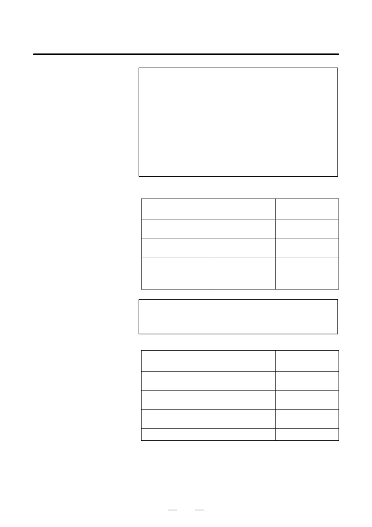
Before a coordinate
After a coordinate
system is established
system is established
Automatic reference posi-
No. 1428
No.1420
tion return (G28)
Automatic rapid traverse
No.1428
No.1420
(G00)
Manual reference position
No.1428
No.1428
return
Manual rapid traverse rate
No.1423 *1
No.1424
NOTE
When parameter No. 1428 is set to 0, the feedrates conform
to the parameter settings shown below.
Before a coordinate
After a coordinate
system is established
system is established
Automatic reference posi-
No. 1420
No.1420
tion return (G28)
Automatic rapid traverse
No.1420
No.1420
(G00)
Manual reference position
No.1424
No.1424
return
Manual rapid traverse rate
No.1423 *1
No.1424
1420 : Rapid traverse rate
1423 : Jog feedrate
1424 : Manual rapid traverse rate
*1 Setting of parameter No.1424 when RPD (bit 0 of parameter No.1401)
is set to 1.
119
6. REFERENCE POSITION
PROGRAMMING
B-63534EN/02
Restrictions
D Status the machine lock
The lamp for indicating the completion of return does not go on when the
being turned on
machine lock is turned on, even when the tool has automatically returned
to the reference position. In this case, it is not checked whether the tool
has returned to the reference position even when a G27 command is
specified.
D First return to the
When the G28 command is specified when manual return to the reference
reference position after
position has not been performed after the power has been turned on, the
the power has been
movement from the intermediate point is the same as in manual return to
turned on (without an
the reference position.
absolute position
In this case, the tool moves in the direction for reference position return
detector)
specified in parameter ZMIx (bit 5 of No. 1006). Therefore the specified
intermediate position must be a position to which reference position
return is possible.
D Reference position
In an offset mode, the position to be reached by the tool with the G27
return check in an offset
command is the position obtained by adding the offset value. Therefore,
mode
if the position with the offset value added is not the reference position, the
lamp does not light up, but an alarm is displayed instead. Usually, cancel
offsets before G27 is commanded.
D Lighting the lamp when
When the machine tool system is an inch system with metric input, the
the programmed position
reference position return lamp may also light up even if the programmed
does not coincide with
position is shifted from the reference position by the least setting
the reference position
increment. This is because the least setting increment of the machine tool
system is smaller than its least command increment.
Reference
Manual reference position
See III-3.1.
return
Examples
G28G90X1000.0Y500.0 ; (Programs movement from A to B)
T1111 ;
(Changing the tool at the reference position)
G29X1300.0Y200.0 ; (Programs movement from B to C)
Reference
Y
The tool is changed at the reference position
R position
500
B
300
A
200
C
200
1000
1300
X
Fig. 6.1 (c) Reference position return and return from the reference
position
120
PROGRAMMING
6. REFERENCE POSITION
B-63534EN/02
6.2
Tools ca be returned to the floating reference position.
A floating reference point is a position on a machine tool, and serves as
FLOATING
a reference point for machine tool operation.
REFERENCE
A floating reference point need not always be fixed, but can be moved as
POSITION RETURN
required.
(G30.1)
Format
G30.1
IP_;
IP
_ :
Command of the intermediate position of the floating reference
position
(Absolute command/incremental command)
Explanations
Generally speaking, on a machining center or milling machine, cutting
tools can be replaced only at specific positions. A position where tools can
be replaced is defined as the second or third reference point. Using G30
can easily move the cutting tools back to these points. On some machine
tools, the cutting tools can be replaced at any position unless they interfere
with the workpiece.
With these machines, the cutting tools should be replaced at a position as
close to the workpiece as possible so as to minimize the machine cycle
time. For this purpose, the tool change position is to be changed,
depending on the figure of the workpiece. This operation can easily be
performed using this function. That is, a tool change position suitable for
the workpiece is memorized as a floating reference point. Then command
G30. 1 can easily cause return to the tool change position.
A floating reference point becomes a machine coordinate position
memorized by pressing the soft key [SET FRP] on the current positions
display screen (see III-11.1.7). The G30.1 block first positions the tool
at the intermediate point along the specified axes at rapid traverse rate,
then further moves the tool from the intermediate point to the floating
reference point at rapid traverse rate.
Before using G30.1, cancel cutter compensation and tool length
compensation.
A floating reference point is not lost even if power is turned off.
The function for returning from the reference position (G29) can be used
for moving the tool from the floating reference position (see II-6.1).
Examples
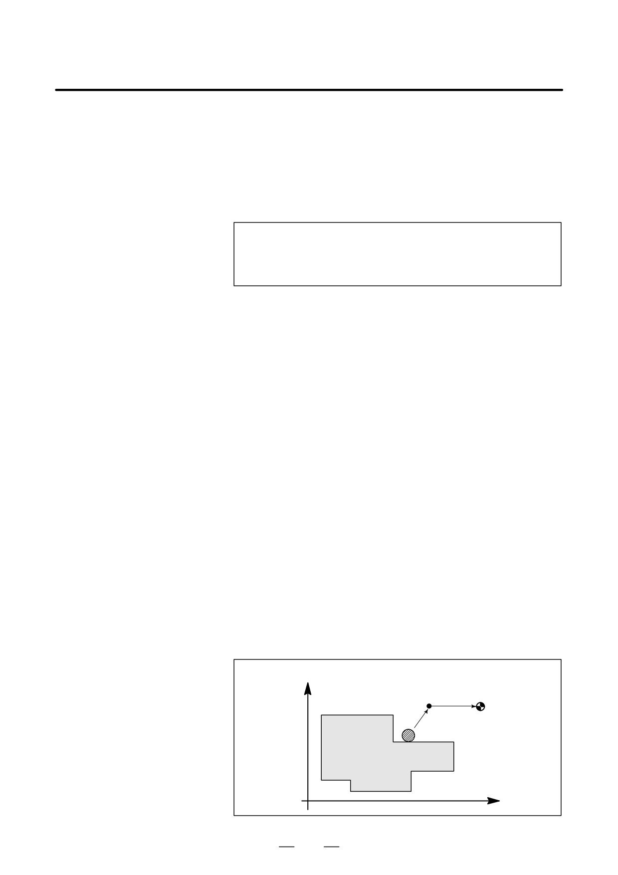
G30.1 G90 X50.0 Y40.0 ;
Y
Intermediate position (50,40)
Floating reference
position
Workpiece
X
121
7. COORDINATE SYSTEM
PROGRAMMING
B-63534EN/02
COORDINATE SYSTEM
7
By teaching the CNC a desired tool position, the tool can be moved to the
position. Such a tool position is represented by coordinates in a
coordinate system. Coordinates are specified using program axes.
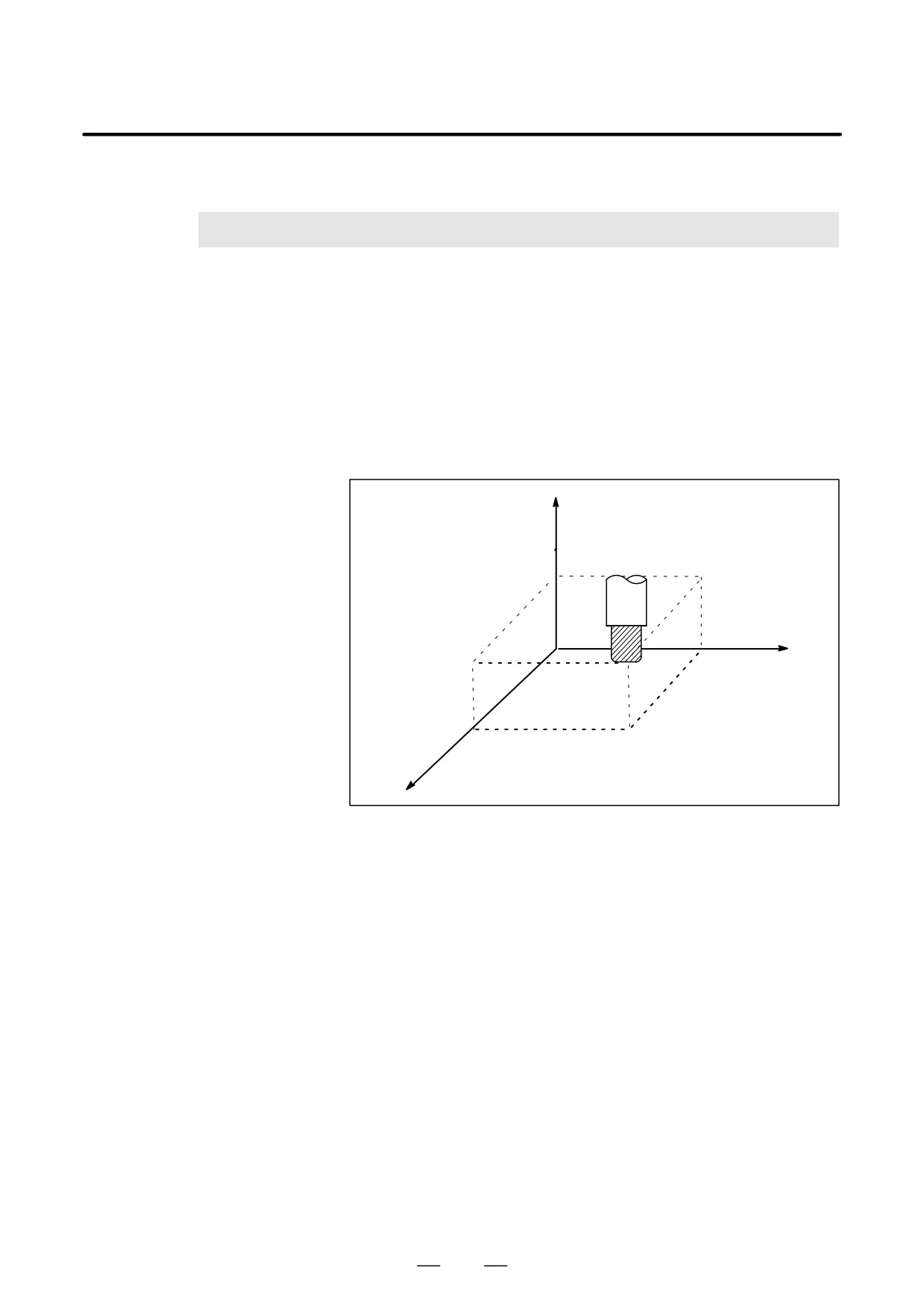
When three program axes, the X-axis, Y-axis, and Z-axis, are used,
coordinates are specified as follows:
X_Y_Z_
This command is referred to as a dimension word.
Z
25.0
Y
50.0
40.0
X
Fig. 7 Tool Position Specified by X40.0Y50.0Z25.0
Coordinates are specified in one of following three coordinate systems:
(1) Machine coordinate system
(2) Workpiece coordinate system
(3) Local coordinate system
The number of the axes of a coordinate system varies from one machine
to another. So, in this manual, a dimension word is represented as IP_.
122
B-63534EN/02
PROGRAMMING
7. COORDINATE SYSTEM
The point that is specific to a machine and serves as the reference of the
7.1
machine is referred to as the machine zero point. A machine tool builder
MACHINE
sets a machine zero point for each machine.
COORDINATE
A coordinate system with a machine zero point set as its origin is referred
to as a machine coordinate system.
SYSTEM
A machine coordinate system is set by performing manual reference
position return after power-on (see III-3.1). A machine coordinate
system, once set, remains unchanged until the power is turned off.
Format
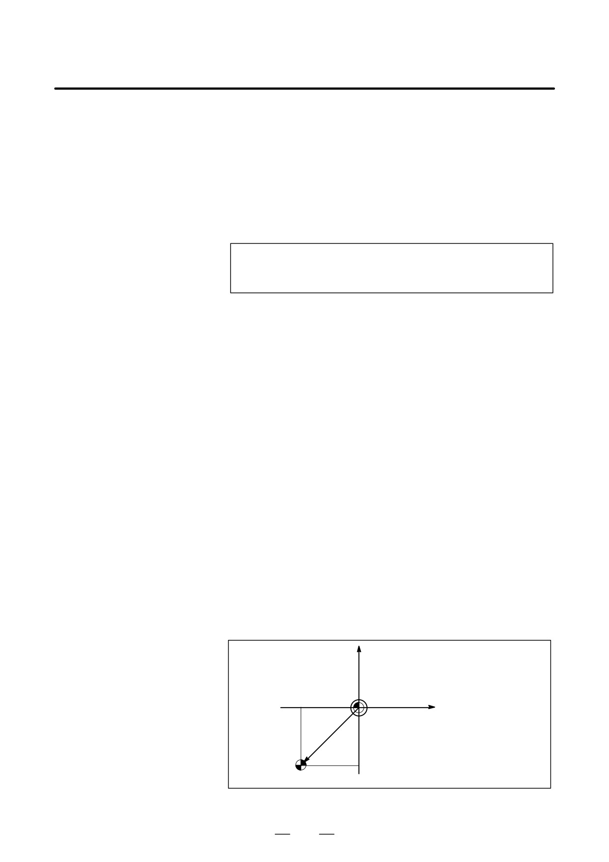
(G90)G53 I
IP
IPP_; Absolute dimension word
Explanations
D Selecting a machine
When a command is specified the position on a machine coordinate
coordinate system (G53)
system, the tool moves to the position by rapid traverse. G53, which is
used to select a machine coordinate system, is a one-shot G code; that is,
it is valid only in the block in which it is specified on a machine coordinate
system. Specify an absolute command (G90) for G53. When an
incremental command (G91) is specified, the G53 command is ignored.
When the tool is to be moved to a machine-specific position such as a tool
change position, program the movement in a machine coordinate system
based on G53.
Restrictions
D Cancel of the
When the G53 command is specified, cancel the cutter compensation, tool
compensation function
length offset, and tool offset.
D G53 specification
Since the machine coordinate system must be set before the G53
immediately after
command is specified, at least one manual reference position return or
power-on
automatic reference position return by the G28 command must be
performed after the power is turned on. This is not necessary when an
absolute-position detector is attached.
Reference
When manual reference position return is performed after power-on, a
machine coordinate system is set so that the reference position is at the
coordinate values of (α, β) set using parameter No.1240.
Machine coordinate system
Machine zero
β
α
Reference position
123
7. COORDINATE SYSTEM
PROGRAMMING
B-63534EN/02
A coordinate system used for machining a workpiece is referred to as a
7.2
workpiece coordinate system. A workpiece coordinate system is to be set
WORKPIECE
with the CNC beforehand (setting a workpiece coordinate system).
COORDINATE
A machining program sets a workpiece coordinate system (selecting a
workpiece coordinate system).
SYSTEM
A set workpiece coordinate system can be changed by shifting its origin
(changing a workpiece coordinate system).
7.2.1
A workpiece coordinate system can be set using one of three methods:
Setting a Workpiece
(1) Method using G92
A workpiece coordinate system is set by specifying a value after G92
Coordinate System
in the program.
(2) Automatic setting
If bit 0 of parameter SPR No. 1201 is set beforehand, a workpiece
coordinate system is automatically set when manual reference
position return is performed (see Part III-3.1.).
(3) Method using G54 to G59
Six workpiece coordinate systems can be set beforehand using the
CRT/MDI panel (see Part III-11.4.6.).
When using an absolute command, establish the workpiece
coordinate system in any of the above ways.
Format
D Setting a workpiece
(G90) G92 IP_
coordinate system by G92
Explanations
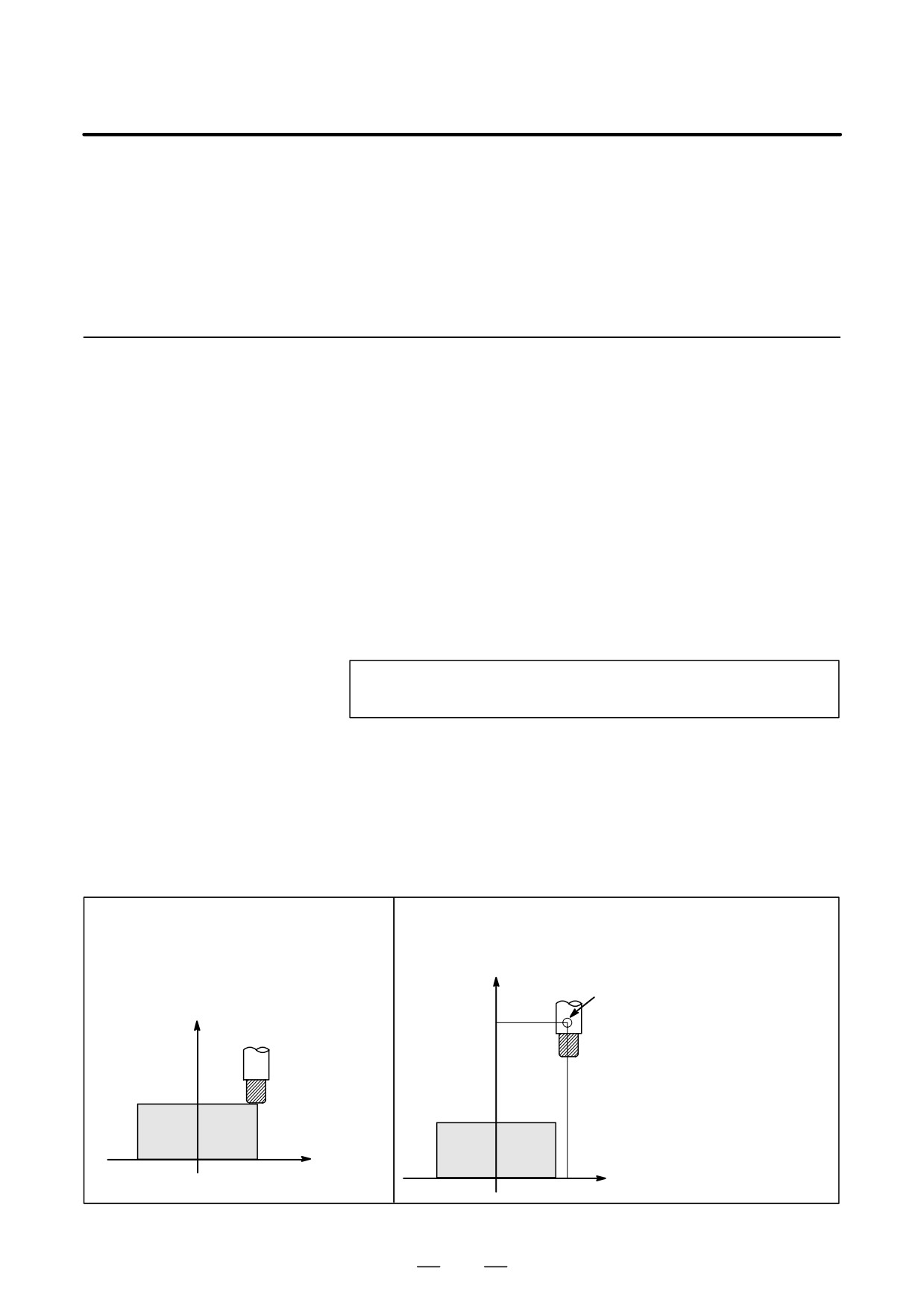
A workpiece coordinate system is set so that a point on the tool, such as
the tool tip, is at specified coordinates. If a coordinate system is set using
G92 during tool length offset, a coordinate system in which the position
before offset matches the position specified in G92 is set.
Cutter compensation is cancelled temporarily with G92.
Examples
Example 1
Example 2
Setting the coordinate system by the
Setting the coordinate system by the G92X600.0Z1200.0; command
G92X25.2Z23.0; command
(The base point on the tool holder is the start point for the program.)
(The tool tip is the start point for the program.)
Z
Base point
If an absolute command is is-
Z
1200.0
sued, the base point moves to
the commanded position. In
order to move the tool tip to the
commanded position, the dif-
23.0
ference from the tool tip to the
base point is compensated by
tool length offset.
0
25.2
X
X
0
600.0
124
B-63534EN/02
PROGRAMMING
7. COORDINATE SYSTEM
7.2.2
The user can choose from set workpiece coordinate systems as described
below. (For information about the methods of setting, see II- 7.2.1.)
Selecting a Workpiece
(1) Once a workpiece coordinate system is selected by G92 or automatic
Coordinate System
workpiece coordinate system setting, absolute commands work with
the workpiece coordinate system.
(2) Choosing from six workpiece coordinate systems set using the MDI
panel
By specifying a G code from G54 to G59, one of the workpiece
coordinate systems 1 to 6 can be selected.
G54 Workpiece coordinate system 1
G55 Workpiece coordinate system 2
G56 Workpiece coordinate system 3
G57 Workpiece coordinate system 4
G58 Workpiece coordinate system 5
G59 Workpiece coordinate system 6
Workpiece coordinate system 1 to 6 are established after reference
position return after the power is turned on. When the power is turned
on, G54 coordinate system is selected.
Examples
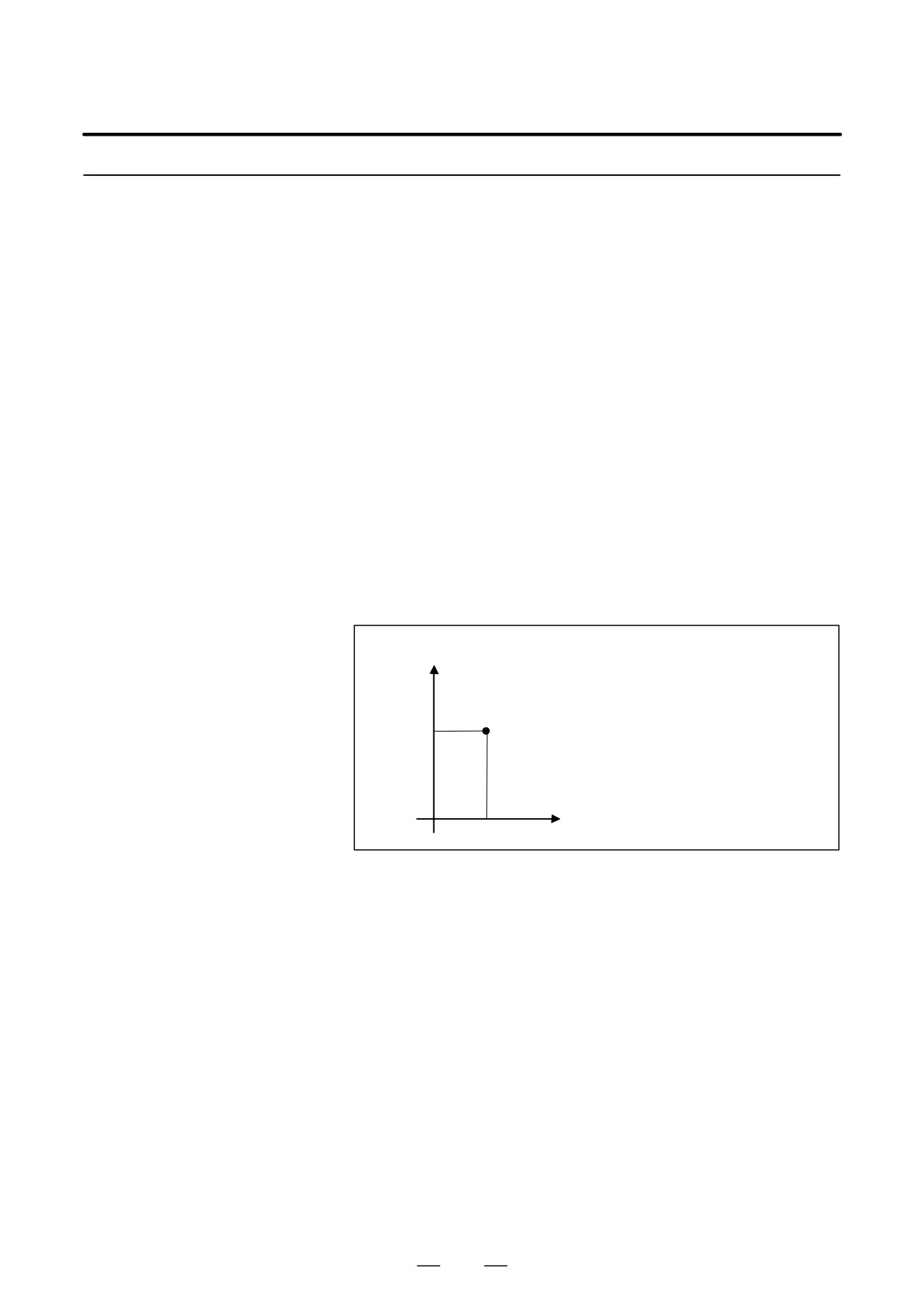
G90 G55 G00 X40.0 Y100.0 ;
Y
Workpiece coordinate system 2 (G55)
100.0
In this example, positioning is made to
positions (X=40.0, Y=100.0) in workpiece
coordinate system 2.
X
40.0
Fig. 7.2.2
125
7. COORDINATE SYSTEM
PROGRAMMING
B-63534EN/02
7.2.3
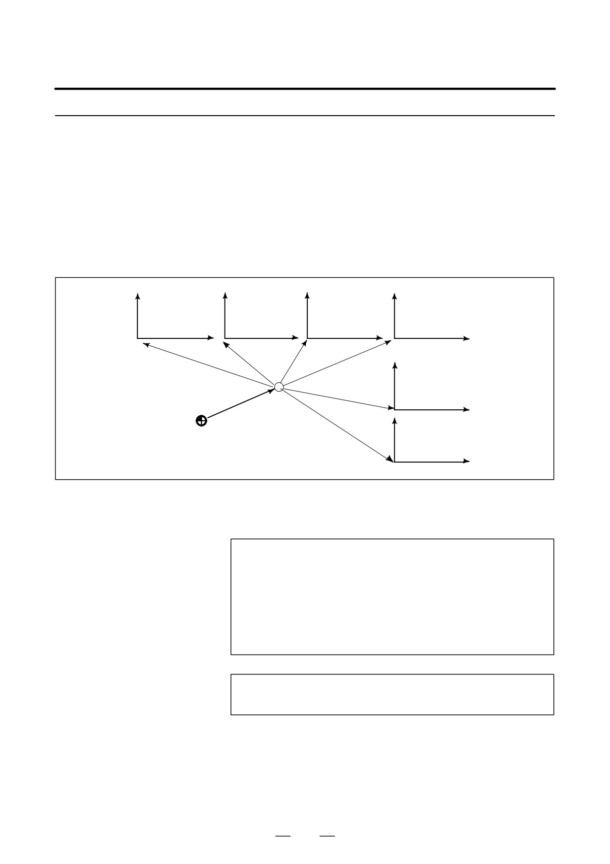
The six workpiece coordinate systems specified with G54 to G59 can
be changed by changing an external workpiece zero point offset value
Changing Workpiece
or workpiece zero point offset value.
Coordinate System
Three methods are available to change an external workpiece zero
point offset value or workpiece zero point offset value.
(1) Inputting from the MDI panel (see III-11.4.6)
(2) Programming by G10 or G92
(3) Using the external data input function
An external workpiece zero point offset value can be changed by
input signal to CNC. Refer to machine tool builder’s manual for
details
Workpiece
Workpiece
Workpiece
Workpiece
coordinate
coordinate
coordinate
coordinate
system 1 (G54)
system 2 (G55)
system 3 (G56)
system 4 (G57)
ZOFS2
ZOFS3
ZOFS1
ZOFS4
Workpiece
coordinate
ZOFS5
system 5 (G58)
EXOFS
ZOFS6
Workpiece
Machine zero
coordinate
system 6 (G59)
EXOFS : External workpiece zero point offset value
ZOFS1 to ZOFS6 : Workpiece zero point offset value
Fig. 7.2.3 Changing an external workpiece zero point offset value or workpiece zero point offset value
Format
G10 L2 Pp IIP
_;
D Changing by G10
p=0
:
External workpiece zero point offset value
p=1 to 6 :
Workpiece zero point offset value correspond to workpiece
coordinate system 1 to 6
II
P
: For an absolute command (G90), workpiece zero point offset for
each axis.
For an incremental command (G91), value to be added to the set
workpiece zero point offset for each axis (the result of addition
becomes the new workpiece zero point offset).
D Changing by G92
G92 I
IP
126

B-63534EN/02
PROGRAMMING
7. COORDINATE SYSTEM
Explanations
D Changing by G10
With the G10 command, each workpiece coordinate system can be
changed separately.
D Changing by G92
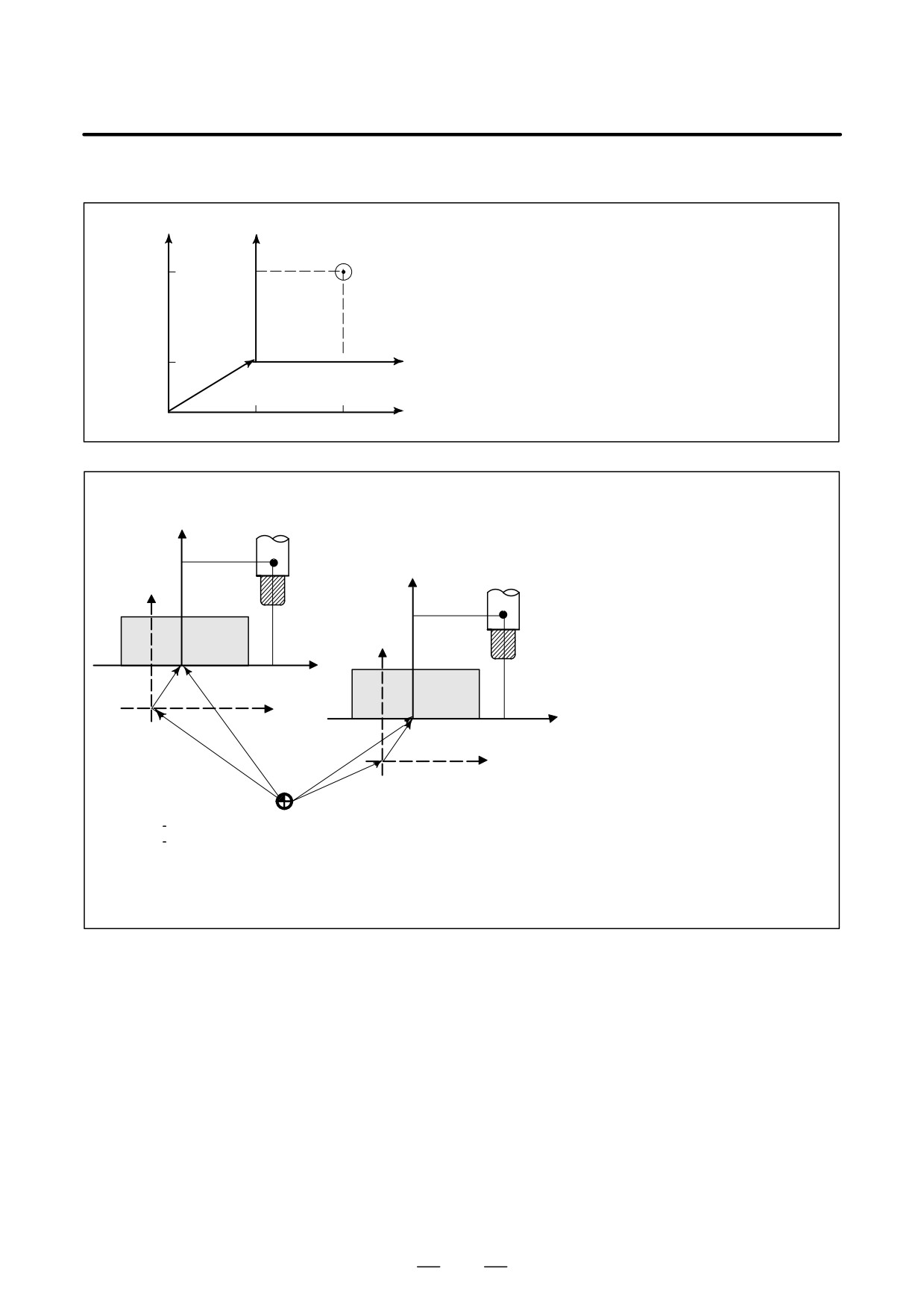
By specifying G92IP_;, a workpiece coordinate system (selected with a
code from G54 to G59) is shifted to set a new workpiece coordinate
system so that the current tool position matches the specified coordinates
( IP _).
Then, the amount of coordinate system shift is added to all the workpiece
zero point offset values. This means that all the workpiece coordinate
systems are shifted by the same amount.
WARNING
When a coordinate system is set with G92 after an external
workpiece zero point offset value is set, the coordinate
system is not affected by the external workpiece zero point
offset value. When G92X100.0Z80.0; is specified, for
example, the coordinate system having its current tool
reference position at X = 100.0 and Z = 80.0 is set.
127
7. COORDINATE SYSTEM
PROGRAMMING
B-63534EN/02
Examples
Y
YȀ
G54 workpiece coordinate system
If G92X100Y100; is commanded when the tool
is positioned at (200, 160) in G54 mode, work-
160
100
Tool position
piece coordinate system 1 (X’ - Y’) shifted by
vector A is created.
60
A
XȀ
New workpiece coordinate system
100
X
Original workpiece coordinate system
100
200
G54 Workpiece
Suppose that a G54 workpiece coordi-
coordinate system
nate system is specified. Then, a G55
Z’
workpiece coordinate system where
G55 Workpiece
the black circle on the tool (figure at the
coordinate system
1200.0
left) is at
(600.0,12000.0) can be set
ZȀ
with the following command if the rela-
tive relationship between the G54 work-
Z
piece coordinate system and G55
1200.0
workpiece coordinate system is set cor-
rectly:G92X600.0Z1200.0;Also, sup-
Z
pose that pallets are loaded at two dif-
X
ferent positions. If the relative relation-
600.0
ship of the coordinate systems of the
A
pallets at the two positions is correctly
set by handling the coordinate systems
X
XȀ
600.0
as the G54 workpiece coordinate sys-
B
A
tem and G55 workpiece coordinate
system, a coordinate system shift with
X
G92 in one pallet causes the same
C
coordinate system shift in the other pal-
let. This means that workpieces on two
pallets can be machined with the same
X’ - Z’ New workpiece coordinate system
program just by specifying G54 or G55.
X - Z Original workpiece coordinate system
A : Offset value created by G92
B : Workpiece zero point offset value in theG54
C : Workpiece zero point offset value in the G55
128
B-63534EN/02
PROGRAMMING
7. COORDINATE SYSTEM
7.2.4
The workpiece coordinate system preset function presets a workpiece
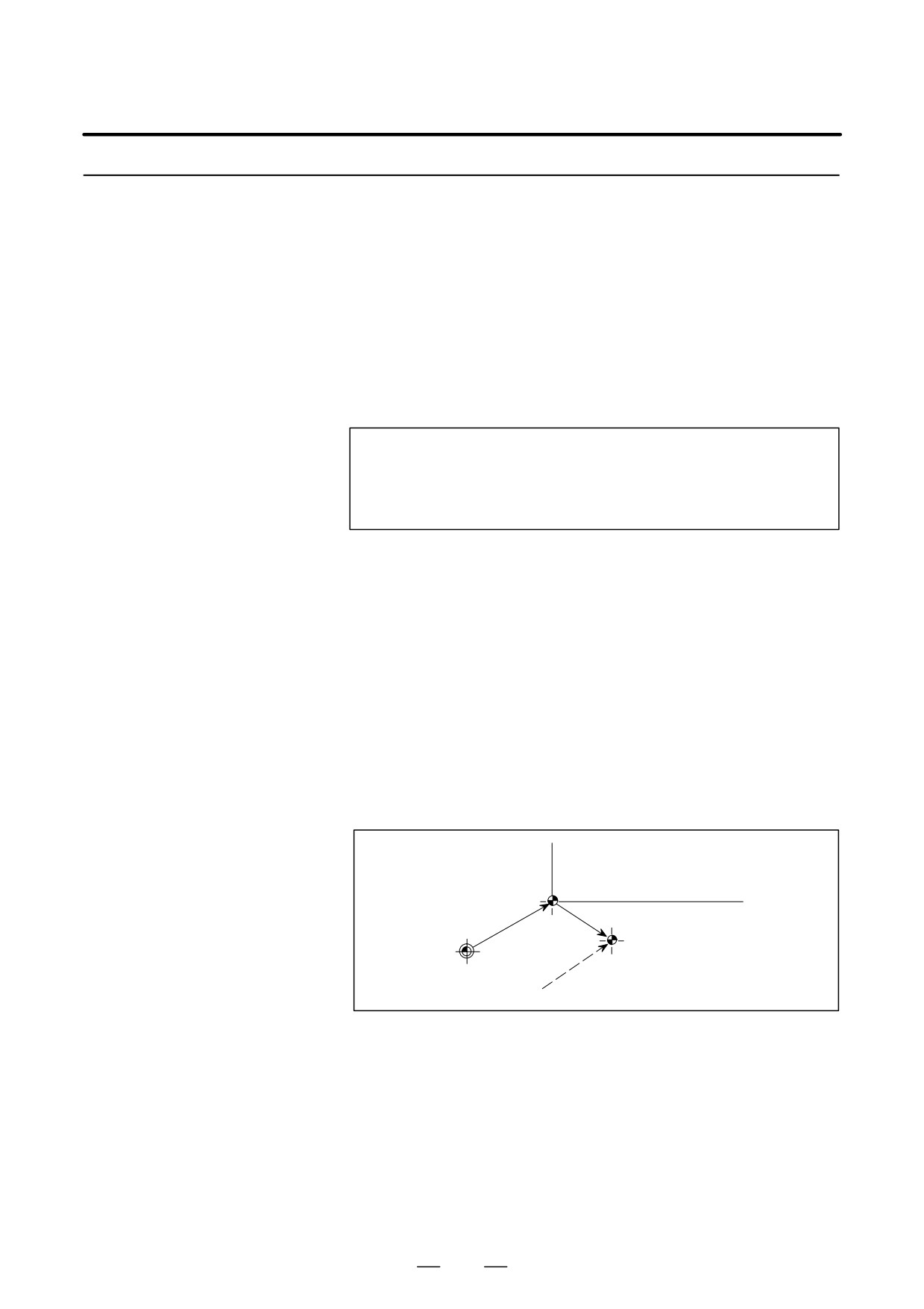
coordinate system shifted by manual intervention to the pre-shift
Workpiece Coordinate
workpiece coordinate system. The latter system is displaced from the
System Preset (G92.1)
machine zero point by a workpiece zero point offset value.
There are two methods for using the workpiece coordinate system preset
function. One method uses a programmed command (G92.1). The other
uses MDI operations on the absolute position display screen, relative
position display screen, and overall position display screen (III-11.1.4).
Format
G92.1 IP 0 ;
IP 0 ; Specifies axis addresses subject to the workpiece
coordinate system preset operation. Axes that are
not specified are not subject to the preset operation.
Explanations
When manual reference position return operation is performed in the reset
state, a workpiece coordinate system is shifted by the workpiece zero
point offset value from the machine coordinate system zero point.
Suppose that the manual reference position return operation is performed
when a workpiece coordinate system is selected with G54. In this case,
a workpiece coordinate system is automatically set which has its zero
point displaced from the machine zero point by the G54 workpiece zero
point offset value; the distance from the zero point of the workpiece
coordinate system to the reference position represents the current position
in the workpiece coordinate system.
G54 workpiece coordinate system
G54 workpiece zero
point offset value
Reference position
Reference position
Manual reference position return
If an absolute position detector is provided, the workpiece coordinate
system automatically set at power-up has its zero point displaced from
the machine zero point by the G54 workpiece zero point offset value. The
machine position at the time of power-up is read from the absolute
position detector and the current position in the workpiece coordinate
system is set by subtracting the G54 workpiece zero point offset value
from this machine position. The workpiece coordinate system set by
these operations is shifted from the machine coordinate system using the
commands and operations listed next page.
129