FANUC Series 16i/160i/160is-MB, Series 18i/180i/180is-MB5, Series 18i/180i/180is-MB. Operator's Manual - page 3
3.
PREPARATORY FUNCTION
(G FUNCTION)
PROGRAMMING
B-63534EN/02
G code list for M series (4/4)
G code
Group
Function
G80
09
Canned cycle cancel/external operation function cancel
G80.5
24
Synchronization start of electronic gear box (EGB) (for two axes program-
ming)
G81
09
Drilling cycle, spot boring cycle or external operation function
G81.1
00
Chopping function
G81.5
24
Synchronization start of electronic gear box (EGB) (for two axes program-
ming)
G82
Drilling cycle or counter boring cycle
G83
Peck drilling cycle
G84
Tapping cycle
G85
Boring cycle
09
G86
Boring cycle
G87
Back boring cycle
G88
Boring cycle
G89
Boring cycle
G90
Absolute command
03
G91
Increment command
G92
Setting for work coordinate system or clamp at maximum spindle speed
00
G92.1
Workpiece coordinate system preset
G94
Feed per minute
05
G95
Feed per rotation
G96
Constant surface speed control
13
G97
Constant surface speed control cancel
G98
Return to initial point in canned cycle
10
G99
Return to R point in canned cycle
G160
In-feed control function cancel(for grinding machine)
20
G161
In-feed control function(for grinding machine)
40
B-63534EN/02
PROGRAMMING
4. INTERPOLATION FUNCTIONS
INTERPOLATION FUNCTIONS
4
41
4. INTERPOLATION FUNCTIONS
PROGRAMMING
B-63534EN/02
4.1
The G00 command moves a tool to the position in the workpiece system
POSITIONING (G00)
specified with an absolute or an incremental command at a rapid traverse
rate.
In the absolute command, coordinate value of the end point is
programmed.
In the incremental command the distance the tool moves is programmed.
Format
G00
IP
_;
IP: For an absolute command, the coordinates of an end
position, and for an incremental commnad, the distance
the tool moves.
Explanations
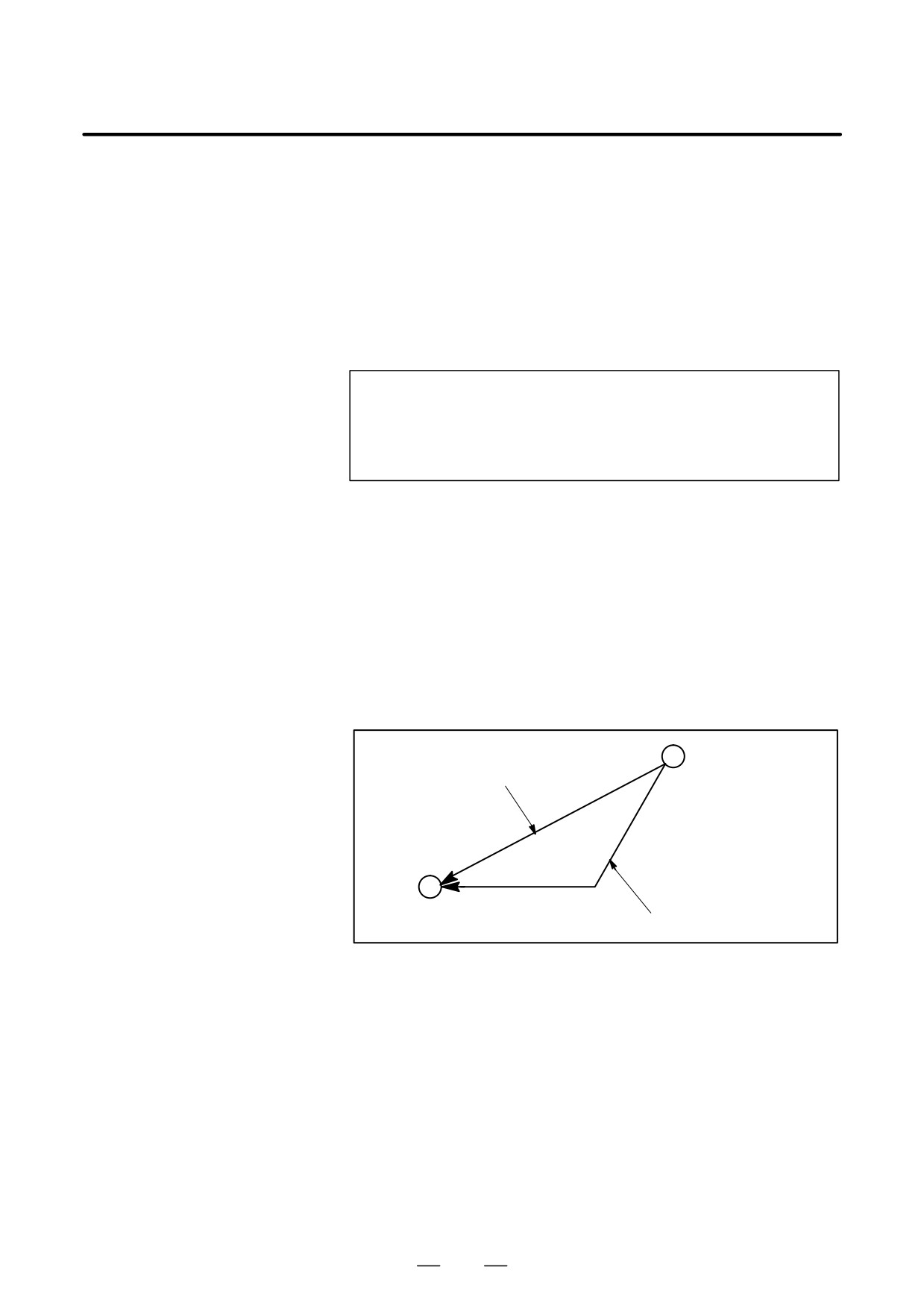
Either of the following tool paths can be selected according to bit 1 of
parameter LRP No. 1401.
D Nonlinear interpolation positioning
The tool is positioned with the rapid traverse rate for each axis
separately. The tool path is normally straight.
D Linear interpolation positioning
The tool path is the same as in linear interpolation (G01). The tool
is positioned within the shortest possible time at a speed that is not
more than the rapid traverse rate for each axis.
Start position
Linear interpolation positioning
End position
Non linear interpolation positioning
The rapid traverse rate in G00 command is set to the parameter No. 1420
for each axis independently by the machine tool builder. In the
posiitoning mode actuated by G00, the tool is accelerated to a
predetermined speed at the start of a block and is decelerated at the end
of a block. Execution proceeds to the next block after confirming the
in-position.
“In-position ” means that the feed motor is within the specified range.
This range is determined by the machine tool builder by setting to
parameter (No. 1826).
In-position check for each block can be disabled by setting bit 5 (NCI)
of parameter No.1601 accordingly.
42
B-63534EN/02
PROGRAMMING
4. INTERPOLATION FUNCTIONS
Limitations
The rapid traverse rate cannot be specified in the address F.
Even if linear interpolation positioning is specified, nonlinear
interpolation positioning is used in the following cases. Therefore, be
careful to ensure that the tool does not foul the workpiece.
D G28 specifying positioning between the reference and intermediate
positions.
D G53
43
4. INTERPOLATION FUNCTIONS
PROGRAMMING
B-63534EN/02
4.2
For accurate positioning without play of the machine (backlash), final
positioning from one direction is available.
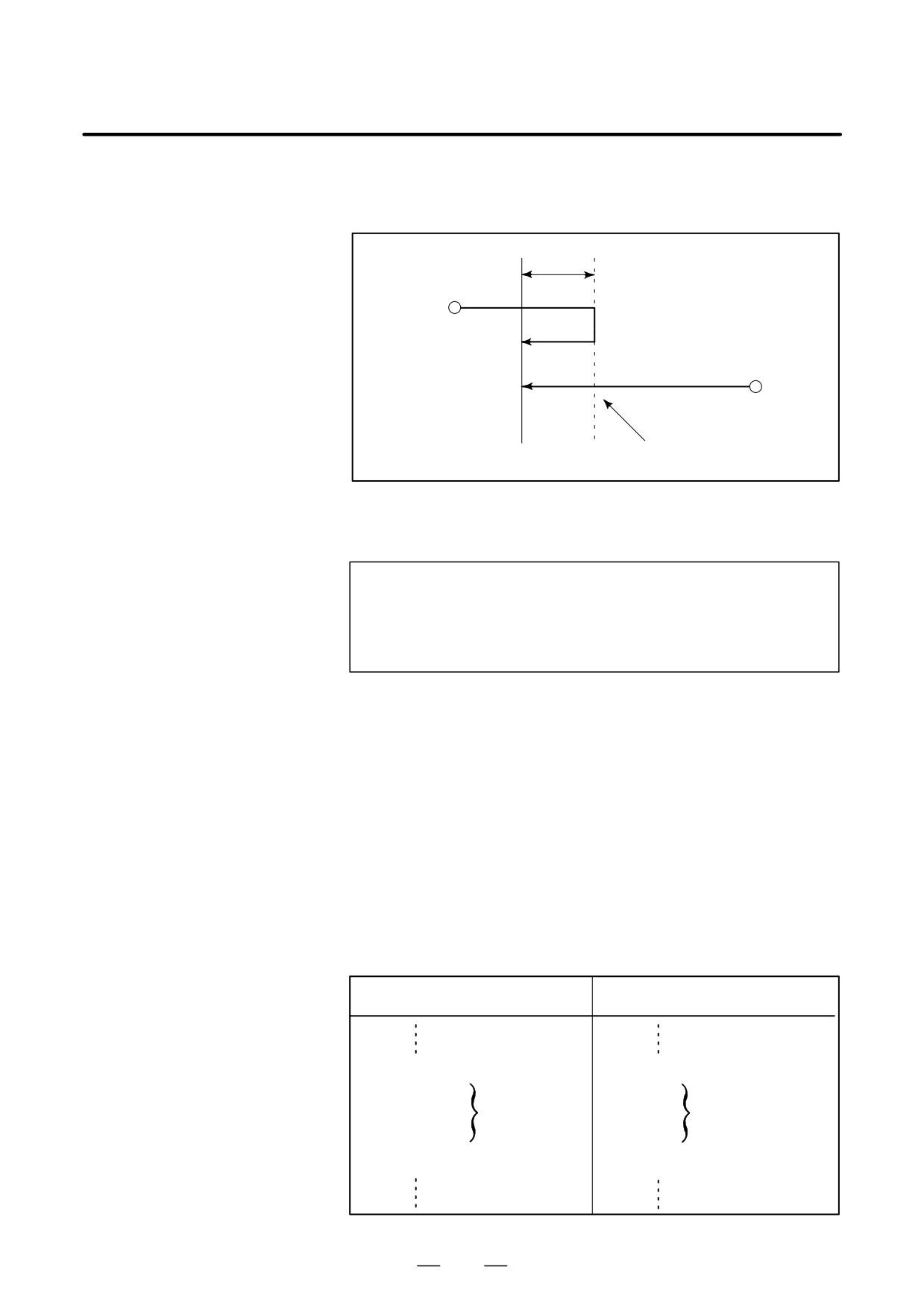
SINGLE DIRECTION
POSITIONING (G60)
Overrun
Start position
Start position
Temporary stop
End position
Format
G60
_;
IP
IP : For an absolute command, the coordinates of an end
position, and for an incremental commnad, the distance
the tool moves.
Explanations
An overrun and a positioning direction are set by the parameter (No.
5440). Even when a commanded positioning direction coincides with
that set by the parameter, the tool stops once before the end point.
G60, which is an one-shot G-code, can be used as a modal G-code in
group 01 by setting 1 to the parameter (No. 5431 bit 0 MDL).
This setting can eliminate specifying a G60 command for every block.
Other specifications are the same as those for an one-shot G60 command.
When an one-shot G code is sepcified in the single direction positioning
mode, the one-shot G command is effective like G codes in group 01.
Examples
When one-shot
When modal
G60 commands are used.
G60 command is used.
G90;
G90G60;
Single direction
positioning mode start
G60
X0Y0;
X0Y0;
Single direction
Single direction
G60
X100;
X100;
positioning
positioning
G60
Y100;
Y100;
G04
X10;
G04X10;
G00
X0Y0;
G00X0Y0; Single direction
positioning
mode cancel
44
B-63534EN/02
PROGRAMMING
4. INTERPOLATION FUNCTIONS
Restrictions
D During canned cycle for drilling, no single direction positioning is
effected in Z axis.
D No single direction positioning is effected in an axis for which no
overrun has been set by the parameter.
D When the move distance 0 is commanded, the single direction
positioning is not performed.
D The direction set to the parameter is not effected by mirror image.
D The single direction positioning does not apply to the shift motion in
the canned cycles of G76 and G87.
45
4. INTERPOLATION FUNCTIONS
PROGRAMMING
B-63534EN/02
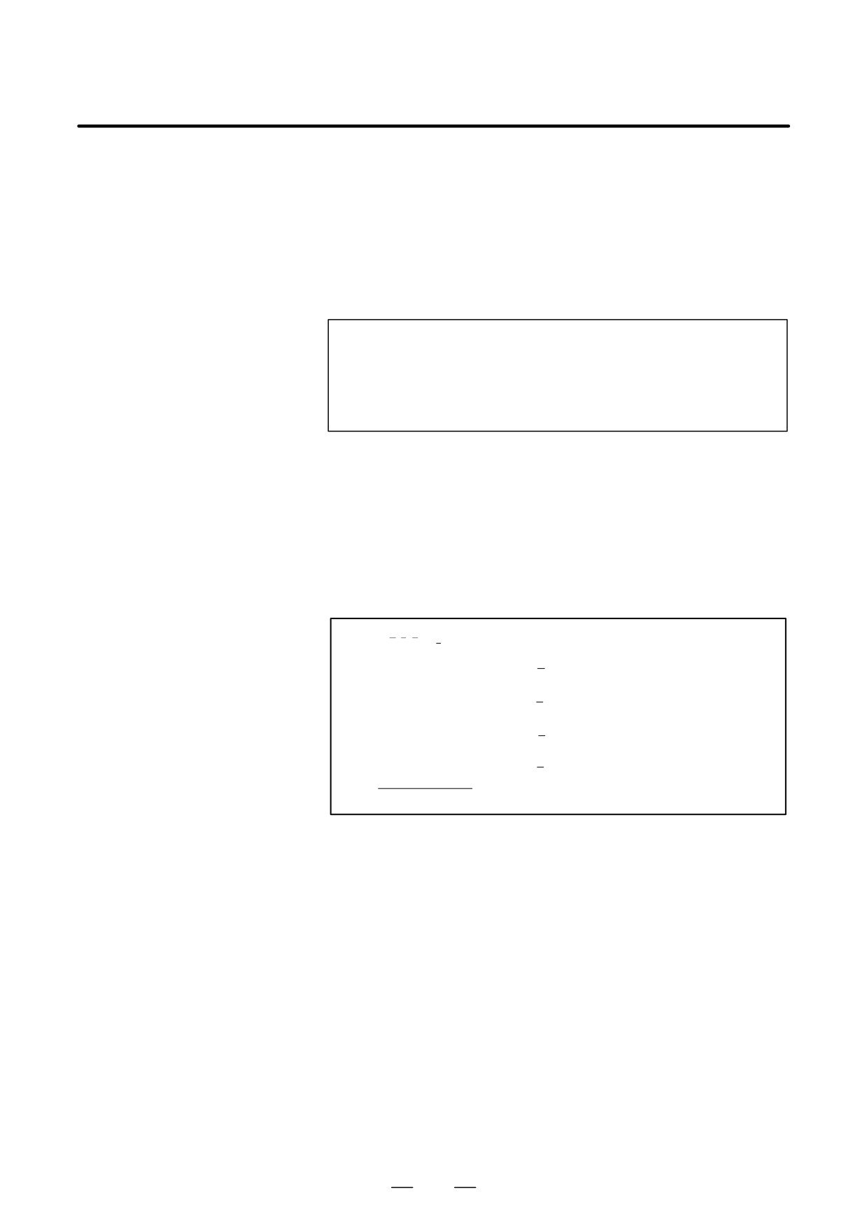
Tools can move along a line
4.3
LINEAR
INTERPOLATION
(G01)
Format
G01
IP_F_;
_:For an absolute command, the coordinates of an end point ,
IP
and for an incremental commnad, the distance the tool moves.
F_:Speed of tool feed (Feedrate)
Explanations
A tools move along a line to the specified position at the feedrate
specified in F.
The feedrate specified in F is effective until a new value is specified. It
need not be specified for each block.
The feedrate commanded by the F code is measured along the tool path.
If the F code is not commanded, the feedrate is regarded as zero.
The feedrate of each axis direction is as follows.
G01ααββγγζζ Ff ;
Feed rate of α axis direction : Fa +a
f
L
b
Feed rate of β axis direction :
Fb +
f
L
g
Feed rate of γ axis direction :
Fg +
f
L
z
Feed rate of ζ axis direction : Fz +
f
L
L + a2 ) b2 ) g2 ) z2Ǹ
The feed rate of the rotary axis is commanded in the unit of deg/min (the
unit is decimal point position).
When the straight line axis α(such as X, Y, or Z) and the rotating axisβ
(such as A, B, or C) are linearly interpolated, the feed rate is that in which
the tangential feed rate in the α and β cartesian coordinate system is
commanded by F(mm/min).
β-axis feedrate is obtained ; at first, the time required for distribution is
calculated by using the above fromula, then the β -axis feedrate unit is
changed to deg/min.
46
B-63534EN/02
PROGRAMMING
4. INTERPOLATION FUNCTIONS
A calculation example is as follows.
G91 G01 X20.0B40.0 F300.0 ;
This changes the unit of the C axis from 40.0 deg to 40mm with metric
input. The time required for distribution is calculated as follows:
Ǹ202 ) 402
8 0.14907
(min)
300
The feed rate for the C axis is
40
8
268.3 degńmin
0.14907
In simultaneous 3 axes control, the feed rate is calculated the same way
as in 2 axes control.
Examples
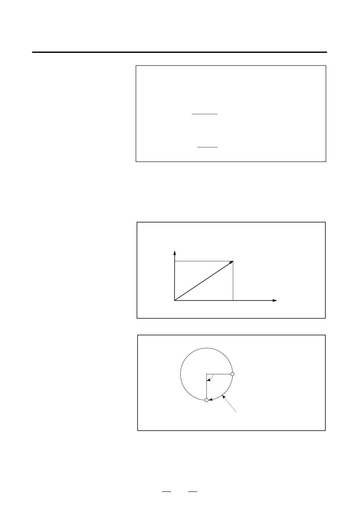
D Linear interpolation
(G91) G01X200.0Y100.0F200.0 ;
Y axis
(End position)
100.0
X axis
0
(Start position)
200.0
D Feedrate for the
rotation axis
G91G01C-90.0 G300.0 ;Feed rate of 300deg/min
(Start point)
90°
(End point)
Feedrate is 300 deg/min
47
4. INTERPOLATION FUNCTIONS
PROGRAMMING
B-63534EN/02
The command below will move a tool along a circular arc.
4.4
CIRCULAR
INTERPOLATION
(G02, G03)
Format
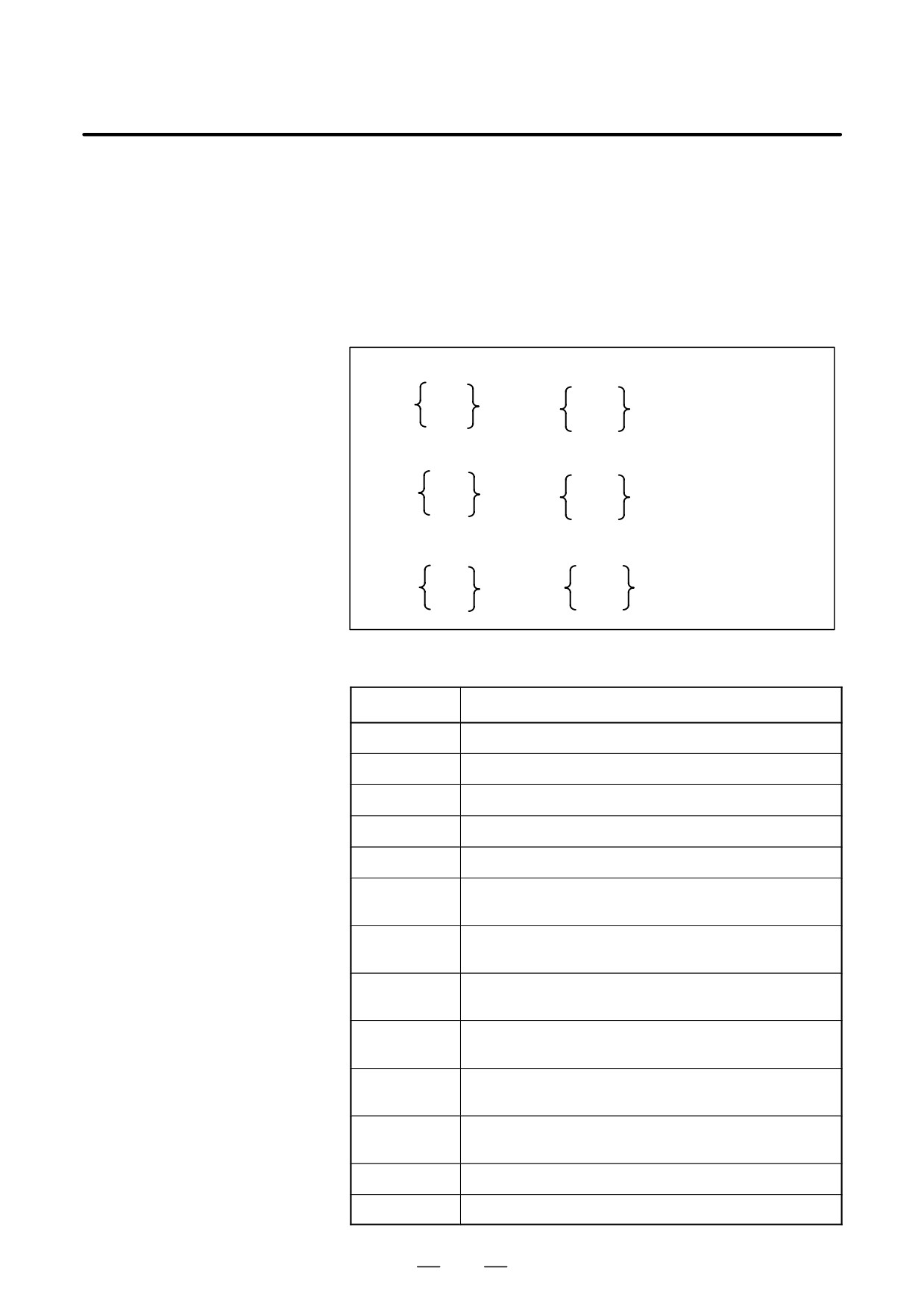
Arc in the XpYp plane
G02
I_ J_
G17
Xp_Yp_
F_ ;
G03
R_
Arc in the ZpXp plane
G02
I_ K_
G18
Xp_ p_
F_
G03
R_
Arc in the YpZp plane
G02
J_ K_
F_
G19
Yp_ Zp_
G03
R_
Table. 4.4 Description of the Command Format
Command
Description
G17
Specification of arc on XpYp plane
G18
Specification of arc on ZpXp plane
G19
Specification of arc on YpZp plane
G02
Circular Interpolation Clockwise direction (CW)
G03
Circular Interpolation Counterclockwise direction (CCW)
Xp_
Command values of X axis or its parallel axis
(set by parameter No. 1022)
Yp_
Command values of Y axis or its parallel axis
(set by parameter No. 1022)
Zp_
Command values of Z axis or its parallel axis
(set by parameter No. 1022)
I_
Xp axis distance from the start point to the center of an arc
with sign
J_
Yp axis distance from the start point to the center of an arc
with sign
k_
Zp axis distance from the start point to the center of an arc
with sign
R_
Arc radius (with sign)
F_
Feedrate along the arc
48

B-63534EN/02
PROGRAMMING
4. INTERPOLATION FUNCTIONS
Explanations
D Direction of the circular
“Clockwise”(G02) and “counterclockwise”(G03) on the XpYp plane
interpolation
(ZpXp plane or YpZp plane) are defined when the XpYp plane is viewed
in the positive-to-negative direction of the Zp axis (Yp axis or Xp axis,
respectively) in the Cartesian coordinate system. See the figure below.
Yp
Xp
Zp
G03
G03
G03
G02
G02
G02
Xp
Zp
Yp
G17
G18
G19
D Distance moved on an
The end point of an arc is specified by address Xp, Yp or Zp, and is
arc
expressed as an absolute or incremental value according to G90 or G91.
For the incremental value, the distance of the end point which is viewed
from the start point of the arc is specified.
D Distance from the start
The arc center is specified by addresses I, J, and K for the Xp, Yp, and Zp
point to the center of arc
axes, respectively. The numerical value following I, J, or K, however, is
a vector component in which the arc center is seen from the start point,
and is always specified as an incremental value irrespective of G90 and
G91, as shown below.
I, J, and K must be signed according to the direction.
End point (x,y)
End point (z,x)
End point (y,z)
y
x
z
x
Start
z
y
i
Start
j
Start
k
point
point
point
j
i
k
Center
Center
Center
I0,J0, and K0 can be omitted. When Xp, Yp , and Zp are omitted (the end
point is the same as the start point) and the center is specified with I, J,
and K, a 360° arc (circle) is specified.
G021; Command for a circle
If the difference between the radius at the start point and that at the
end point exceeds the permitted value in a parameter (No.3410), an P/S
alarm (No.020) occurs.
49
4. INTERPOLATION FUNCTIONS
PROGRAMMING
B-63534EN/02
D Arc radius
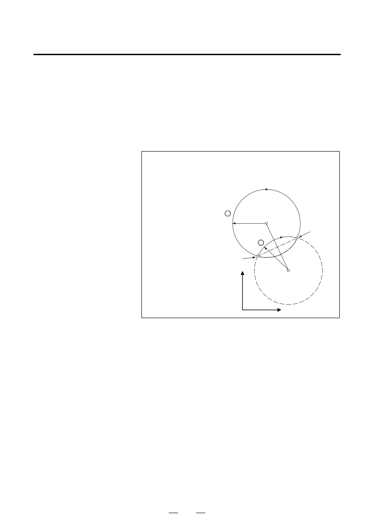
The distance between an arc and the center of a circle that contains the arc
can be specified using the radius, R, of the circle instead of I, J, and K.
In this case, one arc is less than 180°, and the other is more than 180° are
considered. When an arc exceeding 180° is commanded, the radius must
be specified with a negative value. If Xp, Yp, and Zp are all omitted, if
the end point is located at the same position as the start point and when
R is used, an arc of 0° is programmed
G02R ; (The cutter does not move.)
For arc (1)(less than 180°)
G91 G02 XP60.0 YP20.0 R50.0 F300.0 ;
For arc (2)(greater than 180°)
G91 G02 XP60.0 YP20.0 R-50.0 F300.0 ;
2
r=50mm
End point
1
Start point
r=50mm
Y
X
D Feedrate
The feedrate in circular interpolation is equal to the feed rate specified by
the F code, and the feedrate along the arc (the tangential feedrate of the
arc) is controlled to be the specified feedrate.
The error between the specified feedrate and the actual tool feedrate is
±2% or less. However, this feed rate is measured along the arc after the
cutter compensation is applied
Restrictions
If I, J, K, and R addresses are specified simultaneously, the arc specified
by address R takes precedence and the other are ignored.
If an axis not comprising the specified plane is commanded, an alarm is
displayed.
For example, if axis U is specified as a parallel axis to X axis when plane
XY is specified, an P/S alarm (No.028)is displayed.
When an arc having a center angle approaching 180° is specified, the
calculated center coordinates may contain an error. In such a case, specify
the center of the arc with I, J, and K.
50
B-63534EN/02
PROGRAMMING
4. INTERPOLATION FUNCTIONS
Examples
Y axis
100
50R
60
60R
40
0
X axis
90
120 140
200
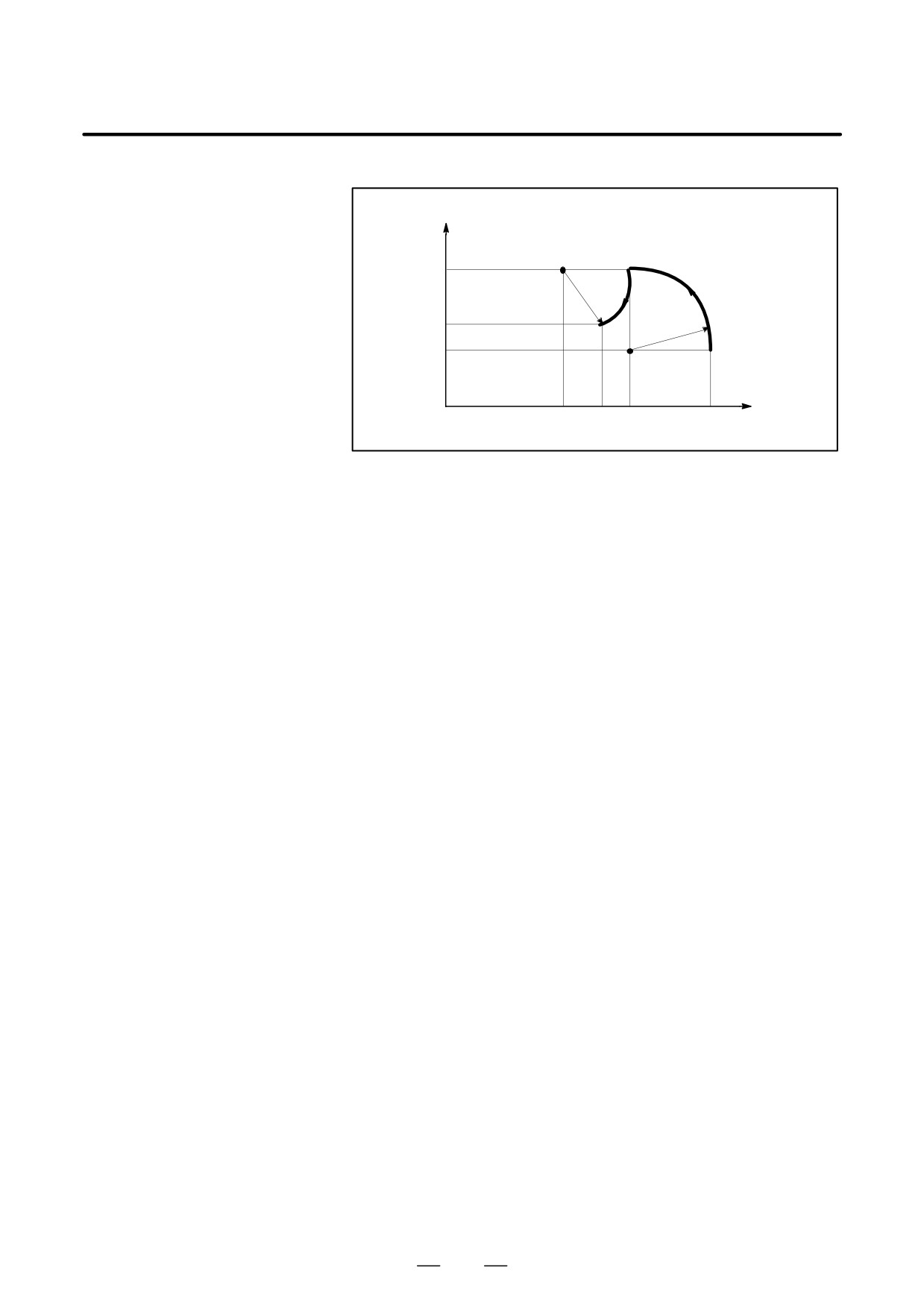
The above tool path can be programmed as follows ;
(1) In absolute programming
G92X200.0 Y40.0 Z0 ;
G90 G03 X140.0 Y100.0R60.0 F300.;
G02 X120.0 Y60.0R50.0 ;
or
G92X200.0 Y40.0Z0 ;
G90 G03 X140.0 Y100.0I-60.0 F300.;
G02 X120.0 Y60.0I-50.0 ;
(2) In incremental programming
G91 G03 X-60.0 Y60.0 R60.0 F300.;
G02 X-20.0 Y-40.0 R50.0 ;
or
G91 G03 X-60.0 Y60.0 I-60.0 F300. ;
G02 X-20.0 Y-40.0 I-50.0 ;
51
4. INTERPOLATION FUNCTIONS
PROGRAMMING
B-63534EN/02
4.5
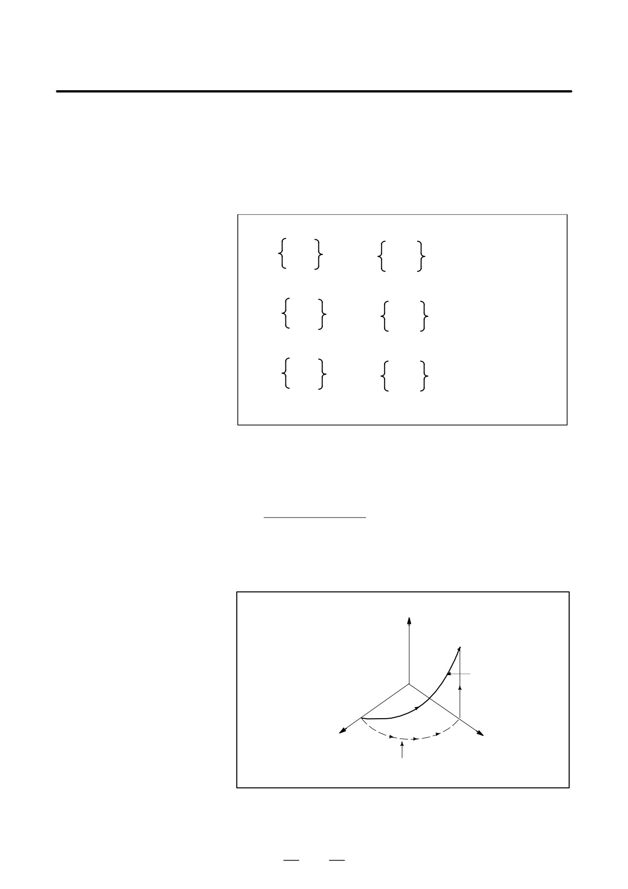
Helical interpolation which moved helically is enabled by specifying up
HELICAL
to two other axes which move synchronously with the circular
INTERPOLATION
interpolation by circular commands.
(G02, G03)
Format
Synchronously with arc of XpYp plane
G02
G17
I_J_
Xp_Yp_
α_(β_)F_;
G03
R_
Synchronously with arc of ZpXp plane
G02
G18
I_K_
Xp_Zp_
α_(β_)F_;
G03
R_
Synchronously with arc of YpZp plane
G02
J_K_
G19
Yp_Zp_
α_(β_)F_;
G03
R_
α,β: Any one axis where circular interpolation is not applied.
Up to two other axes can be specified.
Explanations
The command method is to simply or secondary add a move command
axis which is not circular interpolation axes. An F command specifies a
feed rate along a circular arc. Therefore, the feed rate of the linear axis
is as follows:
Length of linear axis
F×
Length of circular arc
Determine the feed rate so the linear axis feed rate does not exceed any
of the various limit values.Bit 0 (HFC) of parameter No. 1404 can be used
to prevent the linear axis feedrate from exceeding various limit values.
Z
Tool path
X
Y
The feedrate along the circumference of two cir-
cular interpolated axes is the specified feedrate.
Restrictions
⋅Cutter compensation is applied only for a circular arc.
⋅Tool offset and tool length compensation cannot be used in a block in
which a helical interpolation is commanded.
52
B-63534EN/02
PROGRAMMING
4. INTERPOLATION FUNCTIONS
4.6
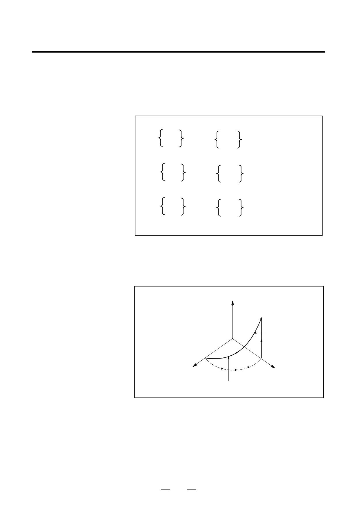
Helical interpolation B moves the tool in a helical manner. This
interpolation can be executed by specifying the circular interpolation
HELICAL
command together with up to four additional axes in simple
INTERPOLATION B
high-precision contour control mode (see II-19.7).
(G02, G03)
Format
With an arc in the XpYp plane
G02
G17
I_J_
Xp_Yp_
α_β_γ_δ_F_;
G03
R_
With an arc in the ZpXp plane
G02
G18
I_K_
Xp_Zp_
α_β_γ_δ_F_;
G03
R_
With an arc in the YpZp plane
G02
J_K_
G19
Yp_Zp_
α_β_γ_δ_F_;
G03
R_
α, β, γ, δ
: Any axis to which circular interpolation is not applied.
Up to four axes can be specified.
Explanations
Basically, the command can be specified by adding two movement axes
to a standard helical interpolation command (see II-4.5). Address F
should be followed by a tangential velocity, which has been determined
by also taking movement along the linear axes into consideration.
Z
Tool path
X
Y
The feedrate equals the tangential velocity determined by also
taking movement along the linear axes into consideration.
Limitations
⋅ The command of helical interpolation B can be specified only in AI
contour control mode.
⋅ Cutter compensation is applied only to an arc.
⋅ In a block containing the helical interpolation command, the tool offset
command or tool length compensation command cannot be specified.
53
4. INTERPOLATION FUNCTIONS
PROGRAMMING
B-63534EN/02
4.7
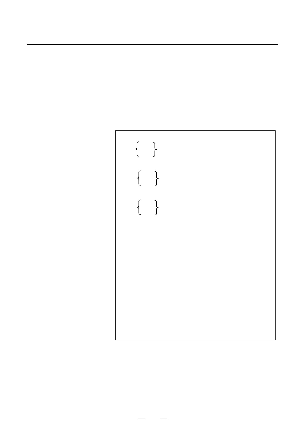
Spiral interpolation is enabled by specifying the circular interpolation
command together with a desired number of revolutions or a desired
SPIRAL
increment (decrement) for the radius per revolution.
INTERPOLATION,
Conical interpolation is enabled by specifying the spiral interpolation
CONICAL
command together with one or two additional axes of movement, as well
as a desired increment (decrement) for the position along the additional
INTERPOLATION
axes per spiral revolution.
(G02, G03)
Format
D Spiral interpolation
XpYp plane
G02
G17
X_ Y_ I_ J_ Q_ L_ F_ ;
G03
ZpXp plane
G02
G18
Z_X_K_ I_ Q_ L_ F_ ;
G03
YpZp plane
G02
G19
Y_ Z_ J_ K_ Q_ L_ F_ ;
G03
X,Y,Z Coordinates of the end point
L
Number of revolutions (positive value without a decimal point)(*1)
Q Radius increment or decrement per spiral revolution(*1)
I,J,K Signed distance from the start point to the center
(same as the distance specified for circular interpolation)
F
Feedrate
(*1) Either the number of revolutions (L) or the radius increment or
decrement (Q) can be omitted. When L is omitted, the number of
revolutions is automatically calculated from the distance between
the current position and the center, the position of the end point,
and the radius increment or decrement. When Q is omitted, the
radius increment or decrement is automatically calculated from the
distance between the current position and the center, the position
of the end point, and the number of revolutions. If both L and Q are
specified but their values contradict, Q takes precedence. Gener-
ally, either L or Q should be specified. The L value must be a posi-
tive value without a decimal point. To specify four revolutions plus
90°, for example, round the number of revolutions up to five and
specify L5.
54
B-63534EN/02
PROGRAMMING
4. INTERPOLATION FUNCTIONS
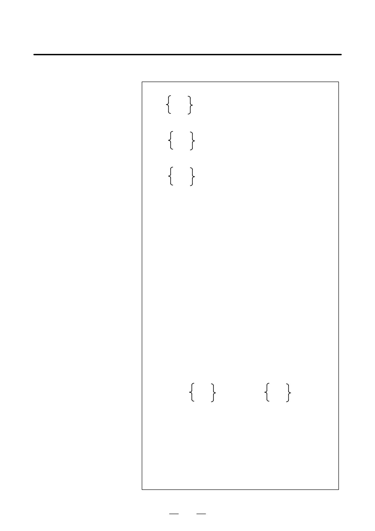
D Conical interpolation
XpYp plane
G02
G17
X_ Y_ Z_ I_ J_ K_ Q_ L_ F_ ;
G03
ZpXp plane
G02
G18
Z_ X_ Y_ K_ I_ J_ Q_ L_ F_ ;
G03
YpZp plane
G19
G02
Y_ Z_ X_ J_ K_ I_ Q_ L_ F_ ;
G03
X,Y,Z Coordinates of the end point
L
Number of revolutions (positive value without a decimal point)(*1)
Q
(Radius increment or decrement per spiral revolution(*1)
I,J,K
Two of the three values represent a signed vector from the start
point to the center. The remaining value is a height increment or
decrement per spiral revolution in conical interpolation(*1)(*2)
When the XpYp plane is selected:
The I and J values represent a signed vector from the start point
to the center.
The K value represents a height increment or decrement per
spiral revolution.
When the ZpXp plane is selected:
The K and I values represent a signed vector from the start point
to the center.
The J value represents a height increment or decrement per
spiral revolution.
When the YpZp plane is selected:
The J and K values represent a signed vector from the start point
to the center.
The I value represents a height increment or decrement per spiral
revolution.
F
Feedrate (determined by taking movement along the linear axes
into consideration)
(*1)
One of the height increment/decrement (I, J, K), radius increment/
decrement (Q), and the number of revolutions (L) must be speci-
fied. The other two items can be omitted.
⋅ Sample command for the XpYp plane
K_
G02
G17
X_ Y_ I_ J_ Z_ ;
Q_
F_ ;
G03
L_
If both L and Q are specified, but their values contradict, Q takes
precedence. If both L and a height increment or decrement are
specified, but their values contradict, the height increment or
decrement takes precedence. If both Q and a height increment or
decrement are specified, but their values contradict, Q takes pre-
cedence. The L value must be a positive value without a decimal
point. To specify four revolutions plus 90°, for example, round the
number of revolutions up to five and specify L5.
(*2)
When two axes (of height) other than plane axes are specified, the
height increment or decrement (I, J, K) cannot be specified. Spec-
ify either a desired radius increment or decrement (Q) or a desired
number of revolutions (L).
55
4. INTERPOLATION FUNCTIONS
PROGRAMMING
B-63534EN/02
Explanations
D Function of spiral
Spiral interpolation in the XY plane is defined as follows:
interpolation
(X - X0)2 + (Y - Y0)2 = (R + Q’)2
X0 : X coordinate of the center
Y0 : Y coordinate of the center
R
: Radius at the beginning of spiral interpolation
Q’ : Variation in radius
When the programmed command is assigned to this function, the
following expression is obtained:
θ
2
(X - XS - I)2 + (Y - YS - J)2 = (R+ĂĂL'Ă+ąąăQ
360
where
XS : X coordinate of the start point
YS : Y coordinate of the start point
I
: X coordinate of the vector from the start point to the center
J
: Y coordinate of the vector from the start point to the center
R
: Radius at the beginning of spiral interpolation
Q : Radius increment or decrement per spiral revolution
L’
:
(Current number of revolutions) - 1
θ
: Angle between the start point and the current position
(degrees)
D Movement between
Block overlap between a spiral/conical interpolation block and other
blocks
blocks is performed only in simple high-precision contour control mode
(see II-NO TAG). In other modes, the movement is decelerated and
stopped in the block before the spiral/conical interpolation block, after
which interpolation starts. After completion of the spiral/conical
interpolation block, the movement is decelerated and stopped, then the
next block is executed.
D Controlled axes
For conical interpolation, two axes of a plane and two additional axes, that
is, four axes in total, can be specified. A rotation axis can be specified as
the additional axis.
D Cutter compensation C
The spiral or conical interpolation command can be programmed in cutter
compensation C mode. At the start and end points of the block, a virtual
circle around the center of the spiral interpolation is drawn. Cutter
compensation is performed along the virtual circle, then spiral
interpolation is performed about the result of the cutter compensation.
When both the start point and end point are at the center, no virtual circle
can be drawn. If drawing is attempted, P/S alarm No. 5124 is issued.
D Feedrate clamping by
During spiral interpolation, the function for clamping the feedrate by arc
arc radius
radius (parameters 1730 to 1732) is enabled. The feedrate may decrease
as the tool approaches the center of the spiral.
D Dry run
When the dry run signal is inverted from 0 to 1 or from 1 to 0 during
movement along an axis, the movement is accelerated or decelerated to
the desired speed without first reducing the speed to zero.
56
B-63534EN/02
PROGRAMMING
4. INTERPOLATION FUNCTIONS
Limitations
D Radius
In spiral or conical interpolation, R for specifying an arc radius cannot be
specified.
D Corner deceleration
Corner deceleration between the spiral/conical interpolation block and
other blocks can be performed only in simple high-precision contour
control mode.
D Feed functions
The functions of feed per rotation, inverse time feed, F command with one
digit, and automatic corner override cannot be used.
D Program restart
A program including spiral or conical interpolation cannot be restarted.
D Retrace
A program including spiral or conical interpolation cannot be retraced.
D Normal direction control
Spiral interpolation and conical interpolation cannot be specified in
normal direction control mode.
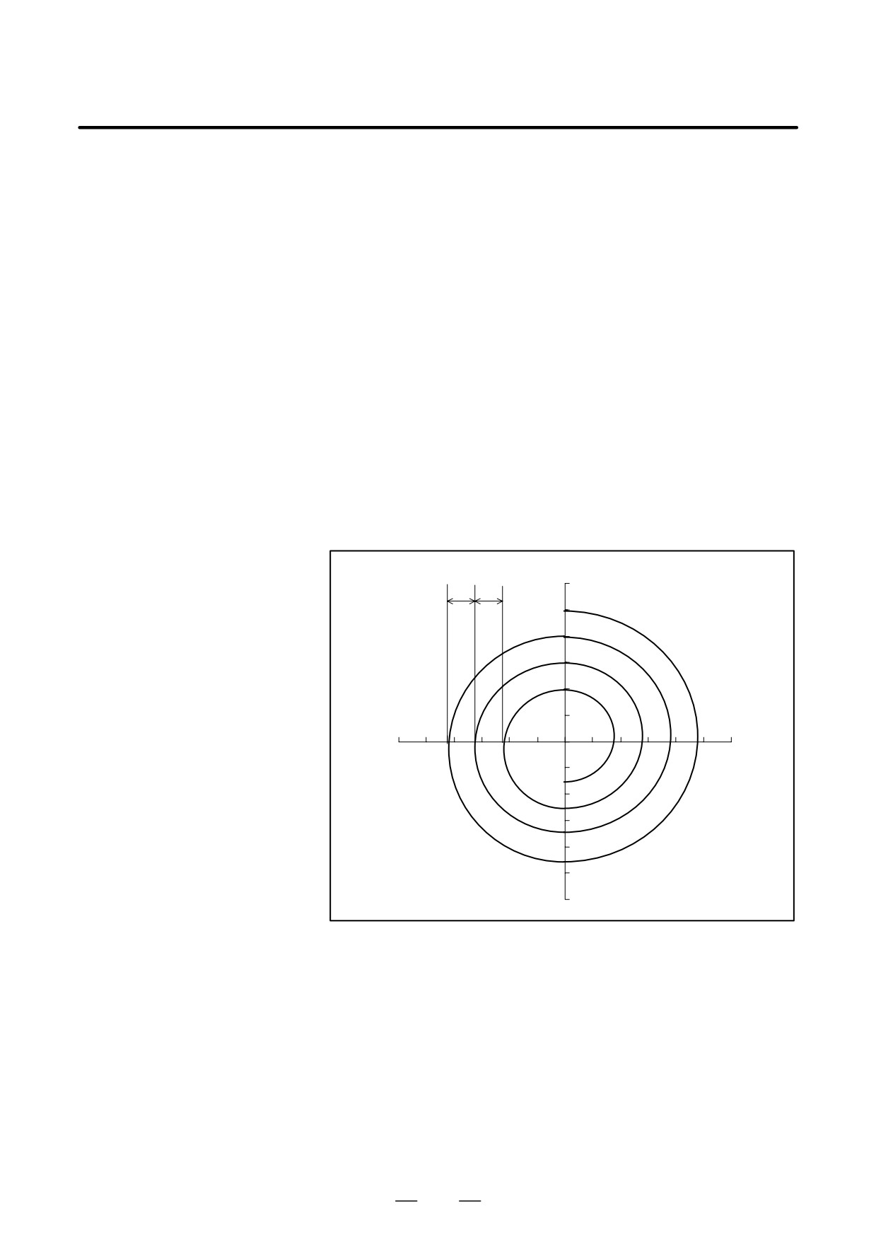
Examples
D Spiral interpolation
20.
20.
120
Y axis
100
80
60
40
20
0
-120-100 -80 -60 -40
-20
0
20
40
60
80
100 120
–20
X axis
-40
-60
-80
-100
-120
The path indicated above is programmed with absolute and incremental
values, as shown below:
This sample path has the following values:
⋅ Start point
:
(0, 100.0)
⋅ End point (X, Y)
:
(0, -30.0)
⋅ Distance to the center (I, J)
:
(0, -100.0)
⋅ Radius increment or decrement (Q) :
-20.0
⋅ Number of revolutions (L)
:
4.
57
4. INTERPOLATION FUNCTIONS
PROGRAMMING
B-63534EN/02
(1) With absolute values, the path is programmed as follows:
Q-20.0
G90 G02 X0 Y-30.0 I0 J-100.0
F300;
L4
(2) With incremental values, the path is programmed as follows:
Q-20.0
G91 G02 X0 Y-130.0 I0 J-100.0
F300;
L4
(Either the Q or L setting can be omitted.)
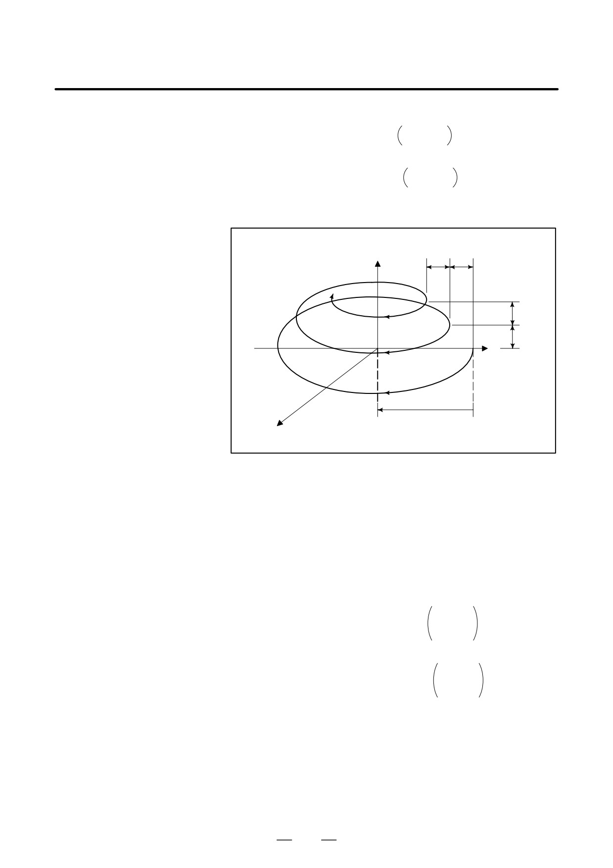
D Conical interpolation
+Z
25.0
25.0
(0,-37.5,62.5)
25.0
25.0
+Y
100.0
-100.0
+X
The sample path shown above is programmed with absolute and
incremental values as follows:
This sample path has the following values:
⋅ Start point
:
(0, 100.0, 0)
⋅ End point (X, Y, Z)
:
(0, -37.5, 62.5)
⋅ Distance to the center (I, J)
:
(0, -100.0)
⋅ Radius increment or decrement (Q) :
-25.0
⋅ Height increment or decrement (K)
:
25.0
⋅ Number of revolutions (L)
:
3
(1) With absolute values, the path is programmed as follows:
K25.0
G90 G02 X0 Y-37.5 Z62.5 I0 J-100.0 Q-25.0
F300;
L3
(2) With incremental values, the path is programmed as follows:
K25.0
G91 G02 X0 Y-137.5 Z62.5 I0 J-100.0 Q-25.0
F300;
L3
58
B-63534EN/02
PROGRAMMING
4. INTERPOLATION FUNCTIONS
Polar coordinate interpolation is a function that exercises contour control
4.8
in converting a command programmed in a Cartesian coordinate system
POLAR COORDINATE
to the movement of a linear axis (movement of a tool) and the movement
INTERPOLATION
of a rotary axis (rotation of a workpiece). This function is useful for
grinding a cam shaft.
(G12.1, G13.1)
Format
G12.1 ;
Starts polar coordinate interpolation mode (enables polar
coordinate interpolation)
Specify linear or circular interpolation using coordinates in a
Cartesian coordinate system consisting of a linear axis and
rotary axis (virtual axis).
G13.1 ;
Polar coordinate interpolation mode is cancelled (for not
performing polar coordinate interpolation)
Specify G12.1 and G13.1 in Separate Blocks.
Explanations
D Polar coordinate
G12.1 starts the polar coordinate interpolation mode and selects a polar
interpolation plane
coordinate interpolation plane (Fig. 4.8 (a)). Polar coordinate
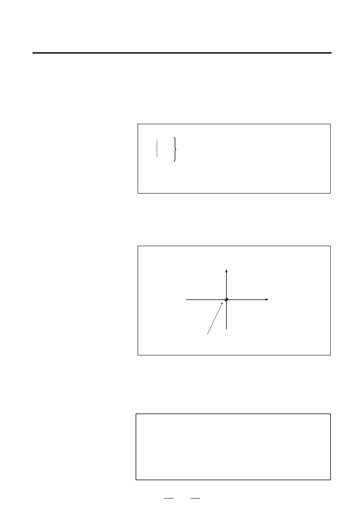
interpolation is performed on this plane.
Rotary axis (virtual axis)
(unit:mm or inch)
Linear axis
(unit:mm or inch)
Origin of the local coordinate system (G52 command)
(Or origin of the workpiece coordinate system)
Fig. 4.8 (a) Polar coordinate interpolation plane.
When the power is turned on or the system is reset, polar coordinate
interpolation is canceled (G13.1).
The linear and rotation axes for polar coordinate interpolation must be set
in parameters (No. 5460 and 5461) beforehand.
CAUTION
The plane used before G12.1 is specified (plane selected
by G17, G18, or G19) is canceled. It is restored when G13.1
(canceling polar coordinate interpolation) is specified.
When the system is reset, polar coordinate interpolation is
canceled and the plane specified by G17, G18, or G19 is
used.
59
4. INTERPOLATION FUNCTIONS
PROGRAMMING
B-63534EN/02
D Distance moved and
In the polar coordinate interpolation mode, program commands are
feedrate for polar
specified with Cartesian coordinates on the polar coordinate interpolation
coordinate interpolation
plane. The axis address for the rotation axis is used as the axis address
for the second axis (virtual axis) in the plane. Whether a diameter or
The unit for coordinates
radius is specified for the first axis in the plane is the same as for the
on the hypothetical axis is
rotation axis regardless of the specification for the first axis in the plane.
the same as the unit for
The virtual axis is at coordinate 0 immediately after G12.1 is specified.
the linear axis (mm/inch)
Polar interpolation is started assuming the angle of 0 for the position of
the tool when G12.1 is specified.
The unit for the feedrate
Specify the feedrate as a speed (relative speed between the workpiece and
is mm/min or inch/min
tool) tangential to the polar coordinate interpolation plane (Cartesian
coordinate system) using F.
D G codes which can be
G01
Linear interpolation
specified in the polar
G02, G03
Circular interpolation
coordinate interpolation
G04
Dwell, Exact stop
mode
G40, G41, G42 . . . Cutter compensation
(Polar coordinate interpolation is applied to the path
after cutter compensation.)
G65, G66, G67 . . . Custom macro command
G90, G91
Absolute command, incremental command
G94, G95
Feed per minute, feed per revolution
D Circular interpolation in
The addresses for specifying the radius of an arc for circular interpolation
the polar coordinate
(G02 or G03) in the polar coordinate interpolation plane depend on the
plane
first axis in the plane (linear axis).
⋅ I and J in the Xp-Yp plane when the linear axis is the X-axis or an axis
parallel to the X-axis.
⋅ J and K in the Yp-Zp plane when the linear axis is the Y-axis or an axis
parallel to the Y-axis.
⋅ K and I in the Zp-Xp plane when the linear axis is the Z-axis or an axis
parallel to the Z-axis.
The radius of an arc can be specified also with an R command.
D Movement along axes
The tool moves along such axes normally, independent of polar
not in the polar
coordinate interpolation.
coordinate interpolation
plane in the polar
coordinate interpolation
mode
D Current position display
Actual coordinates are displayed. However, the remaining distance to
in the polar coordinate
move in a block is displayed based on the coordinates in the polar
interpolation mode
coordinate interpolation plane (Cartesian coordinates).
Limitations
D Coordinate system for
Before G12.1 is specified, a local coordinate system (or workpiece
the polar coordinate
coordinate system) where the center of the rotary axis is the origin of the
interpolation
coordinate system must be set. In the G12.1 mode, the coordinate system
must not be changed (G92, G52, G53, relative coordinate reset, G54
through G59, etc.).
60
B-63534EN/02
PROGRAMMING
4. INTERPOLATION FUNCTIONS
D Tool offset command
The polar coordinate interpolation mode cannot be started or terminated
(G12.1 or G13.1) in the tool offset mode (G41 or G42). G12.1 or G13.1
must be specified in the tool offset canceled mode (G40).
D Tool length offset
Tool length offset must be specified in the polar coordinate interpolation
command
cancel mode before G12.1 is specified. It cannot be
specified in the polar coordinate interpolation mode. Furthermore, no
offset values can be changed in the polar coordinate interpolation mode.
D Tool offset command
A tool offset must be specified before the G12.1 mode is set. No offset
can be changed in the G12.1 mode.
D Program restart
For a block in the G12.1 mode, the program cannot be restarted.
D Cutting feedrate for the
Polar coordinate interpolation converts the tool movement for a figure
rotation axis
programmed in a Cartesian coordinate system to the tool movement in the
rotation axis (C-axis) and the linear axis (X-axis). When the tool moves
closer to the center of the workpiece, the C-axis component of the
feedrate becomes larger and may exceed the maximum cutting feedrate
for the C-axis (set in parameter (No. 1422)), causing an alarm (see the
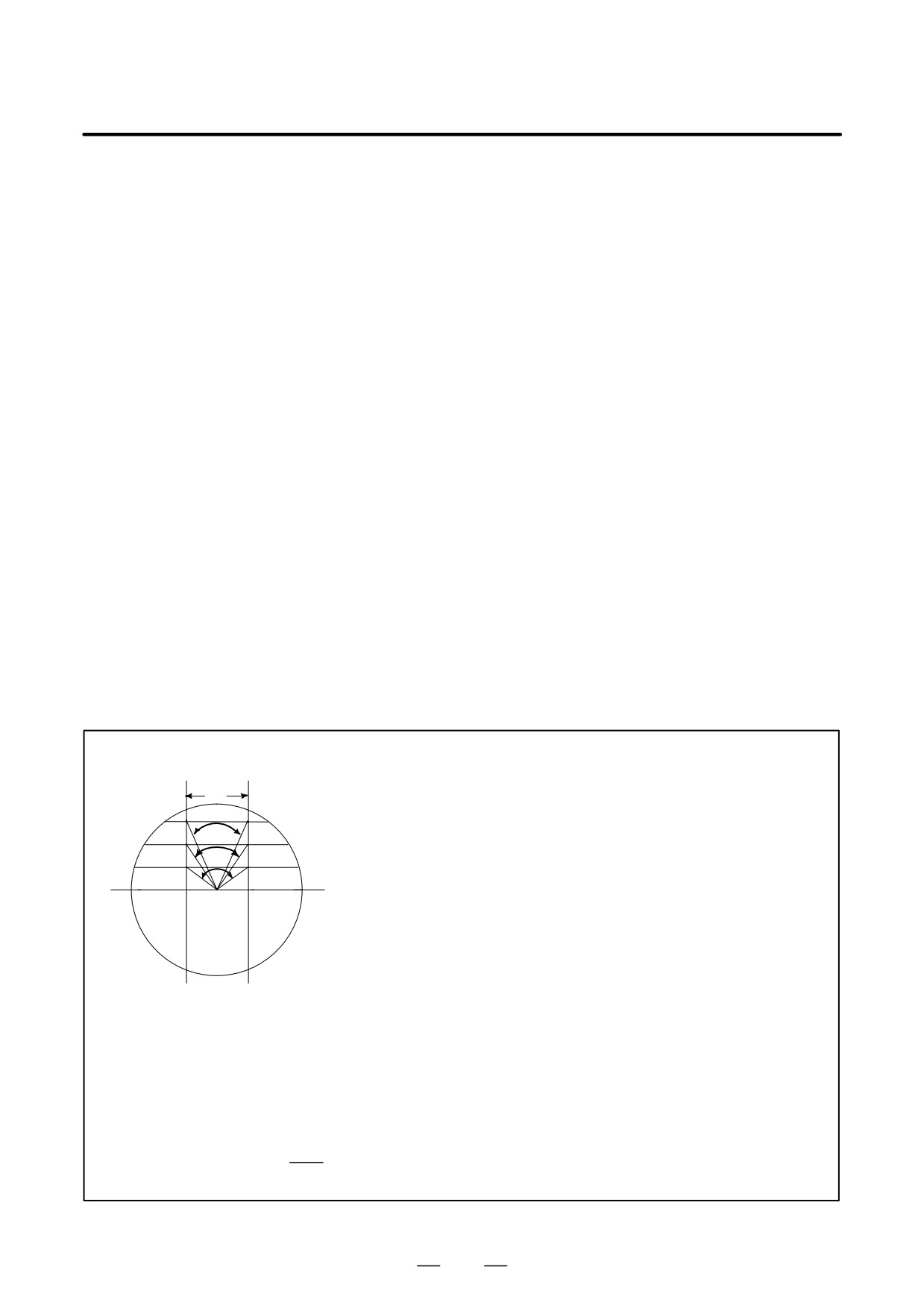
figure below). To prevent the C-axis component from exceeding the
maximum cutting feedrate for the C-axis, reduce the feedrate specified
with address F or create a program so that the tool (center of the tool when
cutter compensation is applied) does not move close to the center of the
workpiece.
WARNING
∆ X
Consider lines L1, L2, and L3. ∆X is the distance the tool moves per time unit
θ1
at the feedrate specified with address F in the Cartesian coordinate system.
L1
As the tool moves from L1 to L2 to L3, the angle at which the tool moves per
θ2
L2
time unit corresponding to ∆X in the Cartesian coordinate system increases
θ3
fromθ1 toθ 2 to θ3.
L3
In other words, the C-axis component of the feedrate becomes larger as the
tool moves closer to the center of the workpiece. The C component of the
feedrate may exceed the maximum cutting feedrate for the C-axis because
the tool movement in the Cartesian coordinate system has been converted to
the tool movement for the C-axis and the X-axis.
L :Distance (in mm) between the tool center and workpiece center when the tool center is the nearest to the
workpiece center
R :Maximum cutting feedrate (deg/min) of the C axis
Then, a speed specifiable with address F in polar coordinate interpolation can be given by the formula below.
Specify a speed allowed by the formula. The formula provides a theoretical value; in practice, a value slightly
smaller than a theoretical value may need to be used due to a calculation error.
π
F < L × R ×
(mm/min)
180
61
4. INTERPOLATION FUNCTIONS
PROGRAMMING
B-63534EN/02
Examples
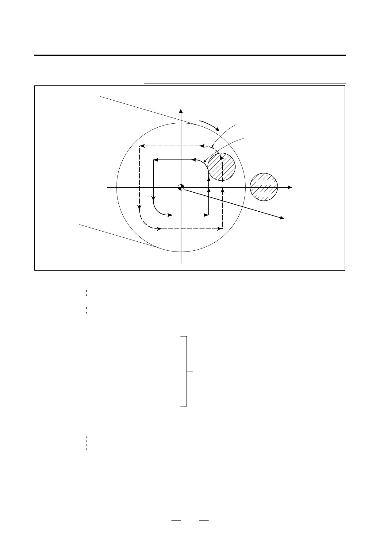
Example of Polar Coordinate Interpolation Program
Based on X Axis(Linear Axis) and C Axis
(Rotary Axis)
C’(hypothetical axis)
C axis
Path after cutter compensation
Program path
N204
N203
N205
N200
N202
N201
X axis
Tool
N208
N206
N207
Z axis
O0001 ;
N010 T0101
N0100 G90 G00 X60.0 C0 Z_ ; Positioning to start position
N0200 G12.1 ;
Start of polar coordinate interpolation
N0201 G42 G01 X20.0 F_ ;
N0202 C10.0 ;
N0203 G03 X10.0 C20.0 R10.0 ;
N0204 G01 X-20.0 ;
Geometry program
N0205 C-10.0 ;
(program based on cartesian coordinates on
N0206 G03 X-10.0 C-20.0 I10.0 J0 ;
X-C’ plane)
N0207 G01 X20.0 ;
N0208 C0 ;
N0209 G40 X60.0 ;
N0210 G13.1 ;
Cancellation of polar coordinate interpolation
N0300 Z_ ;
N0400 X_ C_ ;
N0900M30 ;
62

B-63534EN/02
PROGRAMMING
4. INTERPOLATION FUNCTIONS
The amount of travel of a rotary axis specified by an angle is once
4.9
internally converted to a distance of a linear axis along the outer surface
CYLINDRICAL
so that linear interpolation or circular interpolation can be performed with
INTERPOLATION
another axis. After interpolation, such a distance is converted back to the
amount of travel of the rotary axis.
(G07.1)
The cylindrical interpolation function allows the side of a cylinder to be
developed for programming. So programs such as a program for
cylindrical cam grooving can be created very easily.
Format
G07.1IPr ; Starts the cylindrical interpolation mode
(e
:
:
:
G07.1
IP
0 ; The cylindrical interpolation mode is cancelled.
IP
: An address for the rotation axis
r : The radius of the cylinder
Specify G07.1 IPr ; and G07.1
IP
0; in separate blocks.
G107 can be used instead of G07.1.
Explanations
D Plane selection
Use parameter (No. 1022) to specify whether the rotation axis is the X-,
(G17, G18, G19)
Y-, or Z-axis, or an axis parallel to one of these axes. Specify the G code
to select a plane for which the rotation axis is the specified linear axis.
For example, when the rotation axis is an axis parallel to the X-axis, G17
must specify an Xp-Yp plane, which is a plane defined by the rotation axis
and the Y-axis or an axis parallel to the Y-axis.
Only one rotation axis can be set for cylindrical interpolation.
D Feedrate
A feedrate specified in the cylindrical interpolation mode is a speed on the
developed cylindrical surface.
D Circular interpolation
In the cylindrical interpolation mode, circular interpolation is possible
(G02,G03)
with the rotation axis and another linear axis. Radius R is used in
commands in the same way as described in II-4.4.
The unit for a radius is not degrees but millimeters (for metric input) or
inches (for inch input).
< Example Circular interpolation between the Z axis and C axis >
For the C axis of parameter (No.1022), 5 (axis parallel with the X axis)
is to be set. In this case, the command for circular interpolation is
G18 Z__C__;
G02 (G03) Z__C__R__;
For the C axis of parameter (No.1022), 6 (axis parallel with the Y axis)
may be specified instead. In this case, however, the command for
circular interpolation is
G19 C__Z__;
G02 (G03) Z__C__R__;
63
4. INTERPOLATION FUNCTIONS
PROGRAMMING
B-63534EN/02
D Tool offset
To perform tool offset in the cylindrical interpolation mode, cancel any
ongoing cutter compensation mode before entering the cylindrical
interpolation mode. Then, start and terminate tool offset within the
cylindrical interpolation mode.
D Cylindrical interpolation
In the cylindrical interpolation mode, the amount of travel of a rotary axis
accuracy
specified by an angle is once internally converted to a distance of a linear
axis on the outer surface so that linear interpolation or circular
interpolation can be performed with another axis. After interpolation,
such a distance is converted back to an angle. For this conversion, the
amount of travel is rounded to a least input increment.
So when the radius of a cylinder is small, the actual amount of travel can
differ from a specified amount of travel. Note, however, that such an error
is not accumulative.
If manual operation is performed in the cylindrical interpolation mode
with manual absolute on, an error can occur for the reason described
above.
MOTION REV
2×2πR
The actual amount
Specified value
=
of travel
2×2πR
MOTION REV
MOTION REV : The amount of travel per rotation of the rotation axis
(Setting value of parameter No. 1260)
R
:
Workpiece radius
:
Rounded to the least input increment
Limitations
D Arc radius specification
In the cylindrical interpolation mode, an arc radius cannot be specified
in the cylindrical
with word address I, J, or K.
interpolation mode
D Circular interpolation
If the cylindrical interpolation mode is started when cutter compensation
and cutter compensation
is already applied, circular interpolation is not correctly performed in the
cylindrical interpolation mode.
D Positioning
In the cylindrical interpolation mode, positioning operations (including
those that produce rapid traverse cycles such as G28, G53, G73, G74,
G76, G80 through G89) cannot be specified. Before positioning can be
specified, the cylindrical interpolation mode must be cancelled.
Cylindrical interpolation (G07.1) cannot be performed in the positioning
mode (G00).
D Coordinate system
In the cylindrical interpolation mode, a workpiece coordinate system
setting
(G92, G54 through G59) or local coordinate system (G52) cannot be
specified.
D Cylindrical interpolation
In the cylindrical interpolation mode, the cylindrical interpolation mode
mode setting
cannot be reset. The cylindrical interpolation mode must be cancelled
before the cylindrical interpolation mode can be reset.
D Tool offset
A tool offset must be specified before the cylindrical interpolation mode
is set. No offset can be changed in the cylindrical interpolation mode.
D Index table indexing
Cylindrical interpolation cannot be specified when the index table index
function
function is being used.
64
B-63534EN/02
PROGRAMMING
4. INTERPOLATION FUNCTIONS
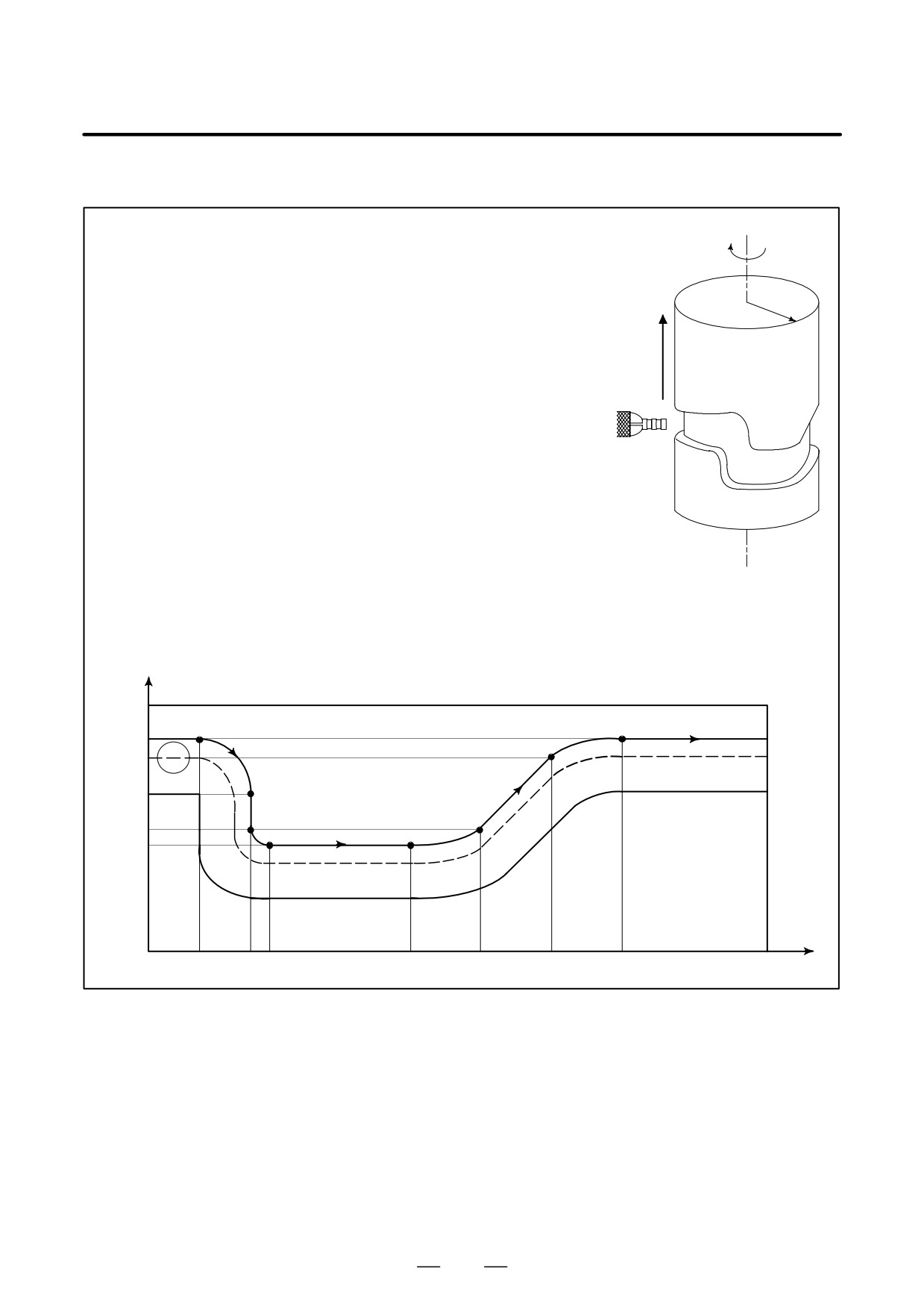
Examples
Example of a Cylindrical Interpolation Program
C
O0001 (CYLINDRICAL INTERPOLATION );
N01 G00 G90 Z100.0 C0 ;
Z
R
N02 G01 G91 G18 Z0 C0 ;
N03 G07.1 C57299 ; (*)
N04 G90 G01 G42 Z120.0 D01 F250 ;
N05 C30.0 ;
N06 G02 Z90.0 C60.0 R30.0 ;
N07 G01 Z70.0 ;
N08 G03 Z60.0 C70.0 R10.0 ;
N09 G01 C150.0 ;
N10 G03 Z70.0 C190.0 R75.0 ;
N11 G01 Z110.0 C230.0 ;
N12 G02 Z120.0 C270.0 R75.0 ;
N13 G01 C360.0 ;
N14 G40 Z100.0 ;
N15 G07.1 C0 ;
N16 M30 ;
* A command with a decimal point can also be used.
Z
mm
N05
N13
N12
120
110
N06
N11
90
N07
70
N08
N09
N10
60
C
0
30
60
70
150
190
230
270
360
deg
65
4. INTERPOLATION FUNCTIONS
PROGRAMMING
B-63534EN/02
4.10
Involute curve machining can be performed by using involute
interpolation. Involute interpolation ensures continuous pulse distribution
INVOLUTE
even in high-speed operation in small blocks, thus enabling smooth and
INTERPOLATION
high-speed machining. Furthermore, machining tapes can be created
(G02.2, G03.2)
easily and efficiently, reducing the required length of tape.
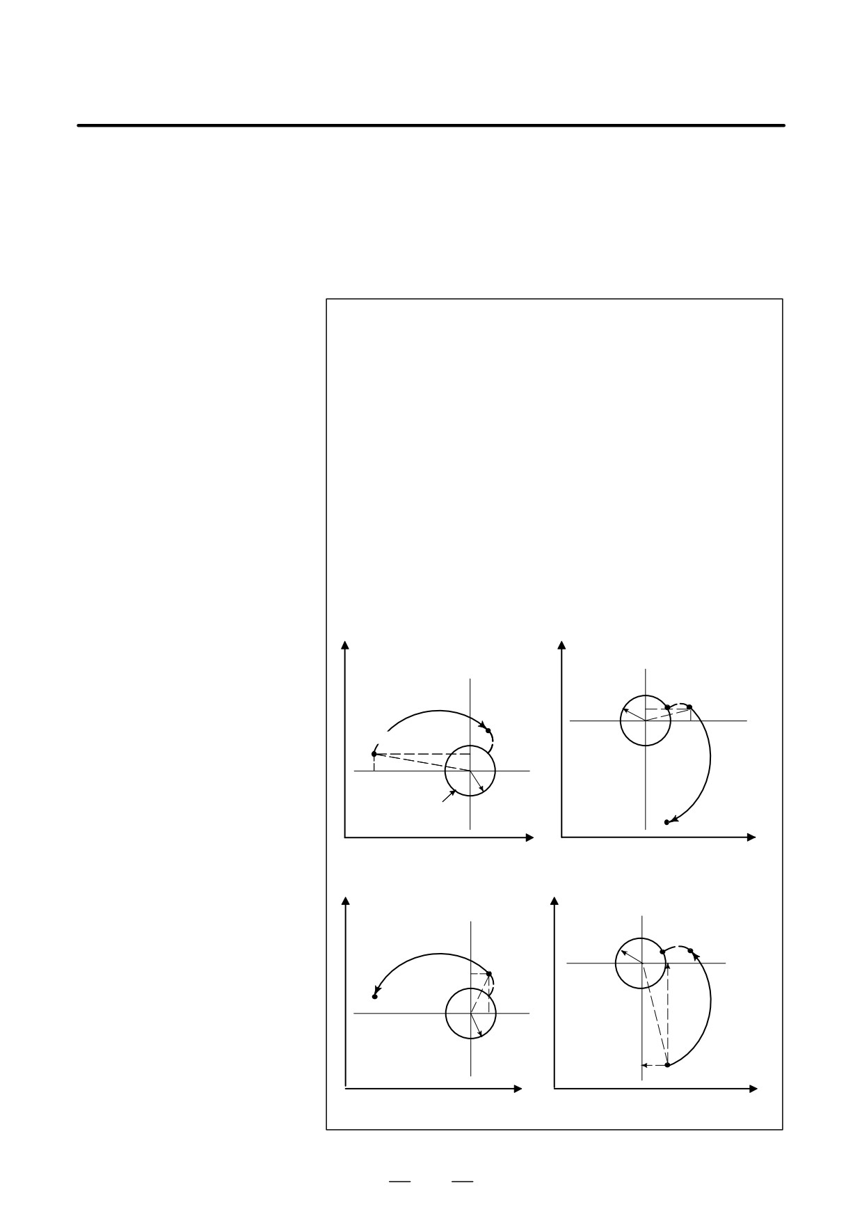
Format
Involute interpolation on the X-Y plane
G17 G02.2 X__Y__I__J__R__F__ ;
G17 G03.2 X__Y__I__J__R__F__ ;
Involute interpolation on the Z-X plane
G18 G02.2 Z__X__K__I__R__F__ ;
G18 G03.2 Z__X__K__I__R__F__ ;
Involute interpolation on the Y-Z plane
G19 G02.2 Y__Z__J__K__R__F__ ;
G19 G03.2 Y__Z__J__K__R__F__ ;
Where,
G02.2 : Involute interpolation (clockwise)
G03.2 : Involute interpolation (counterclockwise)
G17/G18/G19 : X -Y / Z-X / Y-Z plane selection
X, Y, Z
: Involute curve end coordinate
I, J, K : Center of the base circle for an involute curve viewed
from the start point
R : Base circle radius
F : Cutting feedrate
Yp
Yp
Po
Ps
I
R
End point
J
0
Pe
Start point
I
Po
Ps
J
0
R
Base circle
Pe
End point
Xp
Xp
Clockwise involute interpolation (G02.2)
Yp
Yp
End point
Ro
Pe
R
Start point
0
Ps
I
Po
P
e
End point
J
J
0
R
I
Ps
Start point
Xp
Xp
Counterclockwise involute interpolation (G03.2)
66
B-63534EN/02
PROGRAMMING
4. INTERPOLATION FUNCTIONS
Explanations
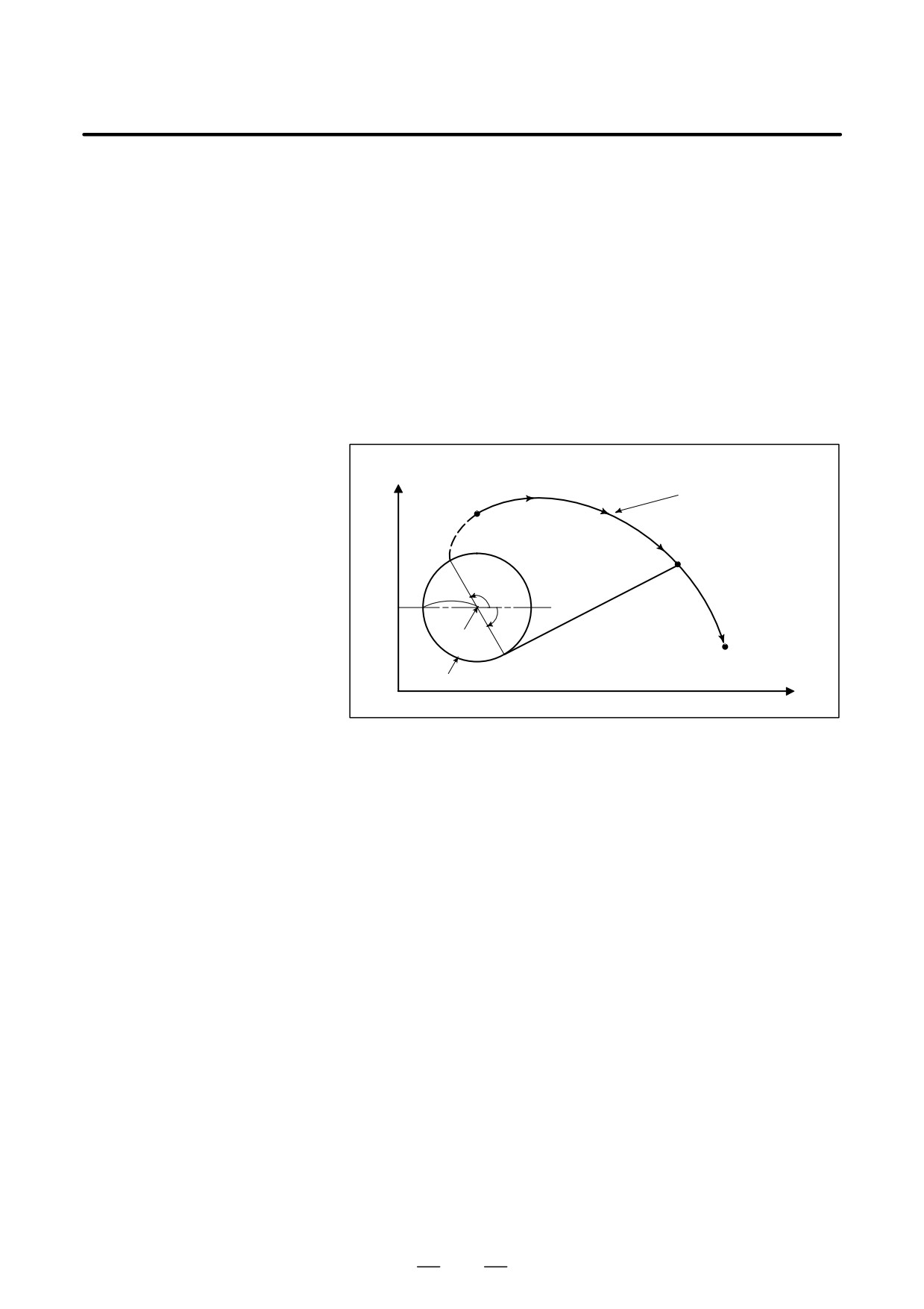
D Involute curve
An involute curve on the X-Y plane is defined as follows ;
X (θ)=R [cos θ+ (θ-θ0 ) sin θ] +X0
Y (θ)=R [sin θ- (θ-θ0 ) cos θ] +Y0
where,
X0 , Y0
: Coordinates of the center of a base circle
R
: Base circle radius
θ0: Angle of the start point of an involute curve
θ
: Angle of the point where a tangent from the current position
to the base circle contacts the base circle
X (θ), Y (θ): Current position on the X-axis and Y-axis
Y
Involute curve
Start point
(X,Y)
R
θ0
θ
(X0,Y0)
End point
Base circle
X
Fig. 4.10 (a) Involute Curve
Involute curves on the Z-X plane and Y-Z plane are defined in the same
way as an involute curve on the X-Y plane.
D Start point and end point
The end point of an involute curve is specified using address X, Y, or Z.
An absolute value or incremental value is used to specify an X, Y, or Z
value. When using an incremental value, specify the coordinates of the
end point viewed from the start point of the involute curve.
When no end point is specified, P/S alarm No. 241 is issued.
If the specified start point or end point lies within the base circle, P/S
alarm No. 242 is issued. The same alarm is issued if cutter compensation
C causes the offset vector to enter the base circle. Be particularly careful
when applying an offset to the inside of an involute curve.
D Base circle specification
The center of a base circle is specified with I, J, and K, corresponding to
X, Y, and Z. The value following I, J, or K is a vector component defined
when the center of the base circle is viewed from the start point of the
involute curve; this value must always be specified as an incremental
value, regardless of the G90/G91 setting. Assign a sign to I, J, and K
according to the direction.
If I, J, and K are all left unspecified, or I0J0K0 is specified, P/S alarm No.
241 or No. 242 is issued.
If R is not specified, or R <
0, P/S alarm No. 241 or No. 242 is issued.
67
4. INTERPOLATION FUNCTIONS
PROGRAMMING
B-63534EN/02
D Choosing from two types
When only a start point and I, J, and K data are given, two types of involute
of involute curves
curves can be created. One type of involute curve extends towards the
base circle, and the other extends away from the base circle. When the
specified end point is closer to the center of the base circle than the start
point, the involute curve extends toward the base circle. In the opposite
case, the involute curve extends away from the base circle.
D Feedrate
The cutting feedrate specified in an F code is used as the feedrate for
involute interpolation. The feedrate along the involute curve (feedrate
along the tangent to the involute curve) is controlled to satisfy the
specified feedrate.
D Plane selection
As with circular interpolation, the plane to which to apply involute
interpolation can be selected using G17, G18, and G19.
D Cutter compensation C
Cutter compensation C can be applied to involute curve machining. As
with linear and circular interpolation, G40, G41, and G42 are used to
specify cutter compensation.
G40 : Cutter compensation cancel
G41 : Cutter compensation left
G42 : Cutter compensation right
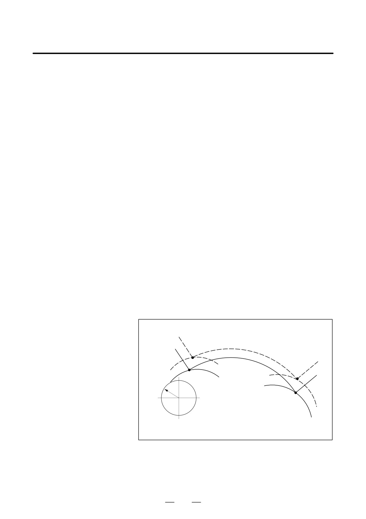
Cutter compensation for an involute curve is implemented as described
below.
First, near the start point of an involute curve, an arc with a curvature close
to the curvature of the involute curve is found. Next, an offset intersection
between the arc and the linear line or arc in the previous block is found.
Similarly, an offset intersection is found near the end point. Then, the
involute curve passing through the two points is used as the tool center
path.
In involute interpolation mode, cutter compensation cannot be started or
cancelled.
Tool center path
Programmed
Start point
path
Arc with a curvature
closer to the curva-
R
ture of the involute
curve near the start
End point
point
Arc with a curvature closer to the
curvature of the involute curve near
the end point
68
B-63534EN/02
PROGRAMMING
4. INTERPOLATION FUNCTIONS
D Specifiable G codes
The following G codes can be specified in involute interpolation mode:
G04 : Dwell
G10 : Data setting
G17 : X-Y plane selection
G18 : Z-X plane selection
G19 : Y-Z plane selection
G65 : Macro call
G66 : Macro modal call
G67 : Macro modal call cancel
G90 : Absolute command
G91 : Incremental command
D Modes that allow
Involute interpolation can be specified in the following G code modes:
involute interpolation
G41 : Cutter compensation left
specification
G42 : Cutter compensation right
G51 : Scaling
G51.1
: Programmable mirror image
G68 : Coordinate rotation
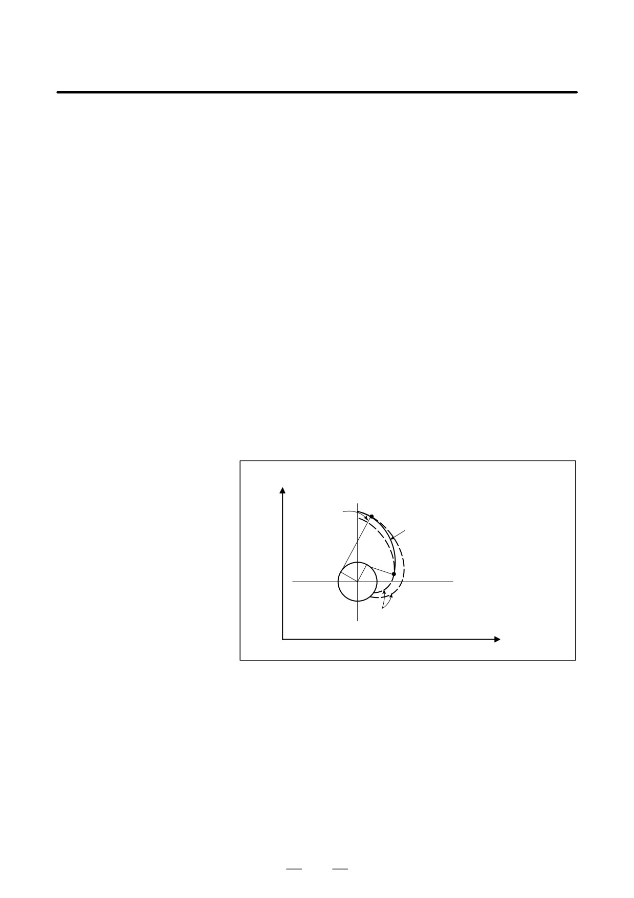
D End point error
As shown below the end point may not be located on an involute curve
that passes through the start point.
When an involute curve that passes through the start point deviates from
the involute curve that passes through the end point by more than the value
set in parameter No. 5610, P/S alarm No. 243 is issued.
When there is an end point error, the feedrate is not guaranteed.
Y
End point
Deviation
Pe
Path after correction
Start
point
Ps
Correct involute curve
X
Fig. 4.10 (b) End Point Error in Counterclockwise Involute Interpolation
(G03.2)
69