FANUC Series 30i/300i/300is-MODEL A. Machining Center System. User's manual - page 224
 

  Index      Manuals     FANUC Series 30i/300i/300is-MODEL A. Machining Center System. User's manual (B-63944EN/03)


Search            copyright infringement  


Content      ..     222      223      224      225     ..


FANUC Series 30i/300i/300is-MODEL A. Machining Center System. User's manual - page 224


12.SETTING AND DISPLAYING DATA

 OPERATION 

B-63944EN/03


- 1748 - 

 - Arbitrary items 

Two arbitrary parameters can be registered. Each item can correspond 
to a CNC parameter or servo parameter. A parameter number 
corresponding to each item is to be specified with parameters. 
 
As indicated below, set the parameters for corresponding parameter 
numbers, velocity-emphasized parameters (precision level 1), and 
precision-emphasized parameters (precision level 10). 
 

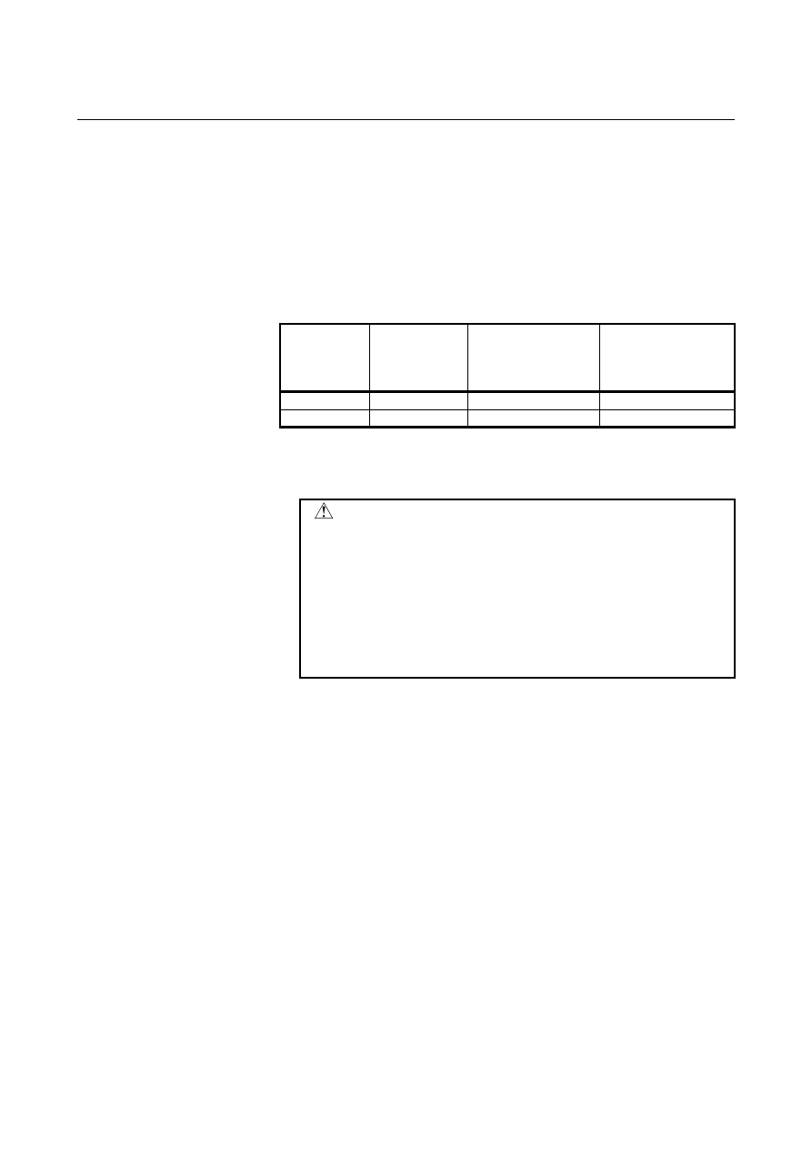
Table 12.4.10 (b) Parameters related to arbitrary items 


Corresponding 

parameter 

number 

Setting of 

velocity-emphasized 

(precision level 1) 

value 

Setting of 

precision-emphasized 

(precision level 10) 

value 

Arbitrary item 1

No.13628 No.13630 

No.13632 

Arbitrary item 2

No.13629 No.13631 

No.13633 


 Display 


Tuning target parameter numbers are displayed. 


 CAUTION 


As arbitrary items, the numbers of the following 
parameters cannot be specified: 

 Bit parameter 

  Spindle parameters (Parameter Nos. 4000 to 

4799) 

 Real-type parameter 

 Power-off parameter 

 Nonexistent parameter 


B-63944EN/03

 OPERATION 

12.SETTING AND DISPLAYING DATA


- 1749 - 

12.4.11 

Displaying Memory Data 

 
The contents of the CNC memory can be displayed starting at a 
specified address. 
 

Displaying memory data 

Procedure 

1  Set bit 0 (MEM) of parameter No. 8950 to 1 to display the 

memory contents display screen. 

Press function key 

Press the continuous menu key 

, then press chapter selection 

soft key [MEMORY]. 
The following screen appears: 


Fig. 12.4.11 (a) Memory contents display screen (10.4-inch) 


4  Key in a desired address (hexadecimal) then press soft key 

[ADDRES SEARCH]. Starting at the specified address, 256-byte 
data is displayed. 


(Example: When you input 100000 then press [ADDRES 
SEARCH], data is displayed starting at 100000H.) 

5  Display data can be switched by using page keys 

 and 

  and cursor keys 

, and/or 

6  By pressing soft key [BYTE], [WORD], [LONG], or [DOUBLE], 

select a data type to be displayed. 


12.SETTING AND DISPLAYING DATA

 OPERATION 

B-63944EN/03


- 1750 - 

Explanation 

A memory data display format can be selected from the following four 
options: 
 
Byte display (1 byte in hexadecimal) 
Word display (2 bytes in hexadecimal) 
Long display (4 bytes in hexadecimal) 
Double display (8 bytes in decimal: Double precision floating-point 
display)  
 
One screen displays 256-byte memory data. 
 

NOTE 

1  When an address is input, "H" for representing 

"hexadecimal" need not be specified at the end of 
the address. If H is added, a warning is displayed 
to indicate that the format is invalid. 

2  When word display is selected as the display 

format, an input address is rounded to a multiple of 
2 bytes. When long display or double display is 
selected, an input address is rounded to a multiple 
of 4 bytes. 


 WARNING 

1  If a memory address that must not be accessed in 

address search is input, a system alarm is issued. 
When making an address search, check that the 
address is accessible and that the address is input 
correctly. 

2  This function is designed for maintenance, and 

must not be used by general users. 


B-63944EN/03

 OPERATION 

12.SETTING AND DISPLAYING DATA


- 1751 - 

12.4.12 

Parameter Tuning Screen 

 
The parameter tuning screen is a screen for parameter setting and 
tuning designed to achieve the following: 
1  The minimum required parameters that must be set when the 

machine is started up are collectively displayed to facilitate 
start-up of the machine. 

The servo tuning screen, spindle tuning screen, and machining 
parameter tuning screen are displayed for smooth tuning. 

The parameter tuning screen consists of a menu screen and several 
setting screens. 
 

12.4.12.1 

Displaying the menu screen and selecting a menu item 

 
The parameter tuning menu screen displays the following items: 
[START UP] 

 SYSTEM 

SETTING 

 AXIS 

SETTING 

 FSSB 

(AMP) 

 FSSB 

(AXIS) 

 SERVO 

SETTING 

 SPINDLE 

SETTING 

 MISCELLANY 

 
[TUNING] 

 SERVO 

TUNING 

 SPINDLE 

TUNING 

 AICC 

TUNING 

 
On the parameter tuning menu screen, one of the displayed items can 
be selected to display the corresponding screen. From each setting 
screen, you can return to the menu screen by performing a soft key 
operation. 
 

NOTE 

1  Some items may not be displayed, depending on 

the system configuration. 

2  When bit 0 (SVS) of parameter No. 3111 is set to 0, 

"SERVO SETTING" and "SERVO TUNING" are not 
displayed. When bit 1 (SPS) of parameter No. 3111 
is set to 0, "SPINDLE TUNING" is not displayed. 


12.SETTING AND DISPLAYING DATA

 OPERATION 

B-63944EN/03


- 1752 - 

Displaying the menu screen and selecting a setting screen 

Procedure 

Set the MDI mode. 

Switch the setting of "PARAMETER WRITE" to "ENABLED". 
For details, see the procedure for "PARAMETER WRITE" in 
Subsection III-12.4.1. 

Press function key 

Press the continuous menu key 

 several times. 

Press soft key [PARAM TUNING] to display the menu screen 
for parameter tuning . 


Fig. 12.4.12.1 (a) Menu screen for parameter tuning (10.4-inch) 


Move the cursor to a desired item by pressing cursor key 


or 

7  Press soft key [SELECT]. The screen display switches to the 

selected screen. 


B-63944EN/03

 OPERATION 

12.SETTING AND DISPLAYING DATA


- 1753 - 

Returning to the menu screen 

Procedure 

1  Press soft key [SELECT] on the parameter tuning menu screen 

described in Subsection III-12.4.12.1. The screen and soft keys 
shown below are displayed. (The screen below is displayed when 
"AXIS SETTING" is selected.) 


Fig. 12.4.12.1 (b) Axis setting screen (10.4-inch) 


Press the continuous menu key 

 several times. 

Press soft key [MENU]. 
The screen display returns to the parameter tuning menu screen. 

4  Upon completion of parameter setting, switch the setting of 

"PARAMETER WRITE" to "DISABLED". 


NOTE 


Some setting screens can also be displayed by a 
chapter selection soft key. If a screen is selected 
using a chapter selection soft key, however, you 
cannot return to the parameter tuning menu screen. 


12.SETTING AND DISPLAYING DATA

 OPERATION 

B-63944EN/03


- 1754 - 

Explanation 
  - Items displayed with [START UP] 

The items of [START UP] indicate the screens for setting the 
minimum required parameters for starting up the machine. 
 

Table 12.4.12.1 (a) Items displayed with [START UP] 

Display item 

Description 

SYSTEM SETTING

Screen for setting CNC parameters related to the entire 
system configuration 

AXIS SETTING 

Screen for setting CNC parameters related to axes, 
coordinates, feedrate, and acceleration/deceleration 

FSSB (AMP) 

FSSB amplifier setting screen 

FSSB (AXIS) 

FSSB axis setting screen 

SERVO SETTING Servo setting screen 

SPINDLE SETTING Screen for setting spindle-related parameters 

MISCELLANY 

Screen for setting parameters related to the allowable 
number of M code digits and whether to display the 
servo setting and spindle tuning screens 


NOTE 


Some items may not be displayed, depending on 
the system configuration. 


  - Items displayed with [TUNING] 

The items of [TUNING] indicate the screens for servo, spindle, and 
high-speed high-precision machining tuning. 
 

Fig. 12.4.12.1 (b) Items displayed with [TUNING] 

Display item 

Description 

SERVO TUNING  Servo tuning screen 

SPINDLE TUNING Spindle tuning screen 

AICC TUNING 

Machining parameter tuning screen 


NOTE 

1  Some items may not be displayed, depending on 

the system configuration. 

2  When bit 0 (SVS) of parameter No. 3111 is set to 

0, "SERVO SETTING" and "SERVO TUNING" are 
not displayed. When bit 1 (SPS) of parameter No. 
3111 is set to 0, "SPINDLE TUNING" is not 
displayed. 


B-63944EN/03

 OPERATION 

12.SETTING AND DISPLAYING DATA


- 1755 - 

12.4.12.2 

Parameter tuning screen (system setting) 

 
This screen enables the parameters related to the entire system 
configuration to be displayed and modified. The parameters can be 
initialized to the standard values (recommended by FANUC). 
 

Display and setting 

Procedure 

Move the cursor to [SYSTEM SETTING] by pressing cursor key 

 or 

  on the parameter tuning menu screen described 

in Subsection III-12.4.12.1. 

2  Press soft key [SELECT]. The screen display switches to the 

screen and soft keys shown below. 


Fig. 12.4.12.2 (a) Parameter tuning screen (system setting) (10.4-inch) 


Move the cursor to a parameter number to be set or displayed, 
according to one of the methods below. 


Enter the parameter number and press soft key [NO.SRH] . 

  Move the cursor to the desired parameter number by 

pressing page key 

 or 

, and cursor keys 

, and/or 


A brief description of the parameter where the cursor is 
placed is provided at the bottom of the screen. However, no 
description is provided when the cursor is placed on 
multiple bits for bit parameters. 

Input desired data then press the 

  key on the MDI panel to 

set the parameter. 


Content      ..     222      223      224      225     ..