FANUC Series 30i/300i/300is-MODEL A. Machining Center System. User's manual - page 223
 

  Index      Manuals     FANUC Series 30i/300i/300is-MODEL A. Machining Center System. User's manual (B-63944EN/03)


Search            copyright infringement  


Content      ..     221      222      223      224     ..


FANUC Series 30i/300i/300is-MODEL A. Machining Center System. User's manual - page 223


12.SETTING AND DISPLAYING DATA

 OPERATION 

B-63944EN/03


- 1740 - 

  - Calling the color (color palette values) 

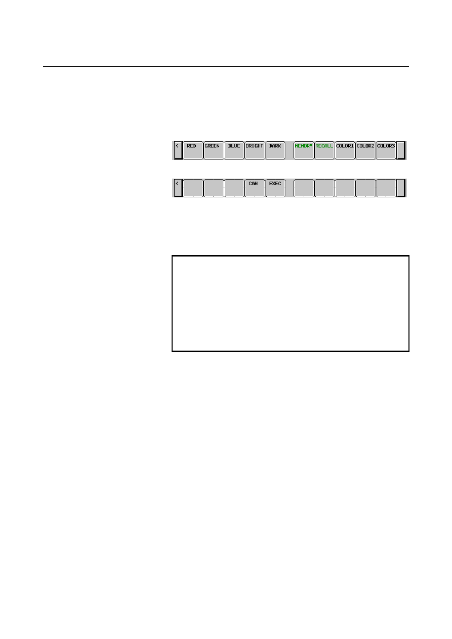
Press operation soft key [COLOR1], [COLOR2], or [COLOR3] 
to select a storage area where color palette values are stored. 
(When operation soft keys [COLOR1], [COLOR2], and 
[COLOR3] are not displayed, press the rightmost soft key to 
display the operation soft keys.) 


2  Press operation soft key [RECALL]. The operation soft key 

display switches to the following: 


Pressing operation soft key [EXEC] calls the color palette values 
from the selected area to enable the color to be modified. This 
operation is invalid if no color palette values are stored. 
Pressing operation soft key [CAN] or the leftmost key does not 
call the color palette values from the selected area. 


NOTE 

1  Immediately after the power is turned on, the 

settings of COLOR1 (parameters) are used for 
display. If nothing is stored for COLOR1, the 
default colors are used for display. 

2  Do not modify the color setting data parameters 

directly by MDI key input. When modifying the 
standard color data, be sure to perform a storage 
operation on the color setting screen. 


B-63944EN/03

 OPERATION 

12.SETTING AND DISPLAYING DATA


- 1741 - 

12.4.10 

Machining Parameter Tuning 

 
In AI contour control, by setting a velocity-emphasized parameter set 
and precision-emphasized parameter set and setting the precision level 
matching a machining condition such as rough machining or finish 
machining on the precision level setting screen or by programming, 
the parameters suitable for the condition can be automatically 
calculated to perform machining. 
On this screen, the parameter sets for emphasis on velocity (precision 
level 1) and emphasis on precision (precision level 10) can be set. 
Set the following parameters: 

 Acceleration rate of acceleration/deceleration before 

interpolation 


Acceleration change time (bell-shaped) 


Allowable acceleration change value for each axis in velocity 
control based on acceleration change under jerk control 


Allowable acceleration change value for each axis in acceleration 
change under jerk control in successive linear interpolation 
operations 


Ratio of the change time of the rate of change of acceleration in 
smooth bell-shaped acceleration/deceleration before interpolation 


Allowable acceleration rate 


Acceleration rate of acceleration/deceleration after interpolation 


Corner speed difference 

 Maximum 

feedrate 


Items that can be set freely (2 items) 

For details of each parameter, see the descriptions of AI contour 
control and jerk control. 
By setting bit 0 (MPR) of parameter No. 13601 to 1, this screen can be 
hidden. 
For the method of setting a precision level, see the description of the 
precision level selection screen in Subsection 11.2.14. 
 

Procedure for machining parameter tuning 

Procedure 

Set the MDI mode. 

Press function key 

3  Press soft key [M-TUN] to display the machining parameter 

tuning screen. 


12.SETTING AND DISPLAYING DATA

 OPERATION 

B-63944EN/03


- 1742 - 


Fig. 12.4.10 (a) Machining parameter tuning screen (10.4-inch) 


Fig. 12.4.10 (b) Machining parameter tuning screen (10.4-inch) 


4  Move the cursor to the position of a parameter to be set, as 

follows: 
Press page key 

 or 

, and cursor keys 

 and /or 

  to move the cursor to the parameter. 

Key in desired data then press the 

  key on the MDI panel. 

6  When data is input, a RMS value is found according to the 

precision level parameters. (The precision level can be changed 
on the precision level selection screen or parameter setting 
screen.) If a RMS value calculation fails, a warning (indicating 
that automatic setting failed) is displayed. 

B-63944EN/03

 OPERATION 

12.SETTING AND DISPLAYING DATA


- 1743 - 

Repeat steps 4 and 5 until all machining parameters are set. 

In addition to the setting method described above, a parameter 
setting method using soft keys is available. Pressing soft key 
[INIT] displays the standard value (recommended by FANUC) of 
the item selected by the cursor in the key input buffer. Pressing 
soft key [EXEC] initializes the item to the standard value. 
Pressing soft key [GROUP INIT] initializes all items of a group 
(emphasis on velocity or emphasis on precision) selected by the 
cursor to the standard values. 

 
The table below indicates the initial settings. 
 

Table 12.4.10 (a) Initial settings 

AI contour control 

Setting item 

Emphasis 

on velocity

(LV1) 

Emphasis 

on precision 

(LV10) 

Unit 

Acceleration rate of acceleration/deceleration before interpolation 
<ACC FOR BIPL> 

4902.000 1042.000 mm/sec

2

Acceleration change time (bell-shaped) <ACC CHG TIME(BELL)> 

32 

64 

msec 

Allowable acceleration change value <JERK ACC DIFF> 

mm/sec

2

Allowable acceleration change value in successive linear 
interpolation operations <JERK ACC DIFF(LIN)> 

0 0 

mm/sec

2

Ratio of the change time of the jerk control <JERK ACC RATIO> 

Allowable acceleration rate <MAX AACELERATION> 

2977.000 

596.000 

mm/sec

2

Time constant for acceleration/deceleration after interpolation   
<T-CON AIPL ACC/DEC> 

24 24 

msec 

Corner speed difference <CORNER FEED DIFFER> 

1000 

400 

mm/min

Maximum cutting speed <MAX CUT FEEDRATE> 

10000 

10000 

mm/min


Explanation 
 - Look-ahead acceleration/deceleration before interpolation 

Set an acceleration rate for a linear portion in look-ahead 
acceleration/deceleration before interpolation. 
Unit of data:    mm/sec

2

, inch/sec

2

, deg/sec

2

 (machine unit) 

 
The parameter set on the machining parameter tuning screen is 
reflected in the following parameters: 
Parameter No. 13610 (velocity-emphasized parameter) 
Parameter No. 13611 (precision-emphasized parameter) 
 
Moreover, the following parameter is also set according to the 
precision level: 
Parameter No. 1660:    Maximum allowable acceleration rate for each 
axis in acceleration/deceleration before interpolation 
 

12.SETTING AND DISPLAYING DATA

 OPERATION 

B-63944EN/03


- 1744 - 

  - Acceleration change time (bell-shaped) 

Set a time constant for a bell-shaped portion in acceleration/ 
deceleration before look-ahead interpolation. 
Unit of data:    ms 
 
The parameter set on the machining parameter tuning screen is 
reflected in the following parameters: 
Parameter No. 13612 (velocity-emphasized parameter) 
Parameter No. 13613 (precision-emphasized parameter) 
 
Moreover, the following parameter is also set according to the 
precision level: 
Parameter No. 1772:  Time  constant  for  bell-shaped  look-ahead 

acceleration/deceleration before interpolation of 
constant acceleration time type 


 CAUTION 


A set time constant is applied to all axes. So, a 
modification made to this item changes the settings 
for all axes. 


  - Allowable acceleration change value in velocity control based on acceleration 

change under jerk control 

Unit of data:    mm/sec

2

, inch/sec

2

, deg/sec

2

 (machine unit) 

 
Set an allowable acceleration change value per ms for each axis in 
velocity control based on acceleration change under jerk control. 
 
The parameter set on the machining parameter tuning screen is 
reflected in the following parameters: 
Parameter No. 13614 (velocity-emphasized parameter) 
Parameter No. 13615 (precision-emphasized parameter) 
 
Moreover, the following parameter is also set according to the 
precision level: 
Parameter No. 1788:  Allowable acceleration change value for each 

axis in velocity control based on acceleration 
change under jerk control 


NOTE 


This setting item is displayed only when the jerk 
control function is enabled. 


B-63944EN/03

 OPERATION 

12.SETTING AND DISPLAYING DATA


- 1745 - 

  - Allowable acceleration change value for each axis in velocity control based on 

acceleration change under jerk control in successive linear interpolation 
operations 

Unit of data:    mm/sec

2

, inch/sec

2

, deg/sec

2

 (machine unit) 

 
Set an allowable acceleration change value per ms for each axis in 
velocity control based on acceleration change under jerk control in 
successive linear interpolation operations. 
 
The parameter set on the machining parameter tuning screen is 
reflected in the following parameters: 
Parameter No. 13616 (velocity-emphasized parameter) 
Parameter No. 13617 (precision-emphasized parameter) 
 
Moreover, the following parameter is also set according to the 
precision level: 
Parameter No. 1789:  Allowable acceleration change value for each 

axis in velocity control based on acceleration 
change under jerk control in successive linear 
interpolation operations 


 CAUTION 

1  For an axis with 0 set in this parameter, the 

parameters (allowable acceleration change value 
in velocity control based on acceleration change 
under jerk control: No. 13614, No.13615) are valid. 

2  For an axis with 0 set in the parameter (allowable 

acceleration change value in velocity control based 
on acceleration change under jerk control: No. 
13614, No.13615), velocity control based on 
acceleration change is disabled, so that this 
parameter has no effect. 


NOTE 


This setting item is displayed only when the jerk 
control function is enabled. 


12.SETTING AND DISPLAYING DATA

 OPERATION 

B-63944EN/03


- 1746 - 

  - Ratio of the change time of the jerk control in smooth bell-shaped 

acceleration/deceleration before interpolation 

Unit of data:    % 
 
Set the ratio (in %) of the change time of jerk control to the change 
time of acceleration in smooth bell-shaped acceleration/deceleration 
before interpolation. 
 
The parameter set on the machining parameter tuning screen is 
reflected in the following parameters: 
Parameter No. 13618 (velocity-emphasized parameter) 
Parameter No. 13619 (precision-emphasized parameter) 
 
Moreover, the following parameter is also set according to the 
precision level: 
Parameter No. 1790:  Ratio of the change time of the jerk control in 

smooth bell-shaped acceleration/deceleration 
before interpolation 


NOTE 


This setting item is displayed only when the jerk 
control function is enabled. 


  - Allowable acceleration rate 

Set an allowable acceleration rate in acceleration-based speed 
determination. 
Unit of data:    mm/sec

2

, inch/sec

2

, deg/sec

2

 (machine unit) 

 
The parameter set on the machining parameter tuning screen is 
reflected in the following parameters: 
Parameter No. 13620 (velocity-emphasized parameter) 
Parameter No. 13621 (precision-emphasized parameter) 
 
Moreover, the following parameter is also set according to the 
precision level: 
Parameter No. 1735:  Allowable acceleration rate for each axis 

applicable to the deceleration function based 
on acceleration in circular interpolation 

Parameter No. 1737:  Allowable acceleration rate for each axis 

applicable to the deceleration function based 
on acceleration in AI contour control 


 CAUTION 


When bit 0 (MCR) of parameter No. 13600 is set to 
1, the deceleration function based on acceleration 
in circular interpolation is not set. 


B-63944EN/03

 OPERATION 

12.SETTING AND DISPLAYING DATA


- 1747 - 

  - Time constant for acceleration/deceleration after interpolation 

Set a time constant for acceleration/deceleration after interpolation. 
Unit of data:    ms 
 
The parameter set on the machining parameter tuning screen is 
reflected in the following parameters: 
Parameter No. 13622 (velocity-emphasized parameter) 
Parameter No. 13623 (precision-emphasized parameter) 
 
Moreover, the following parameter is also set according to the 
precision level: 
Parameter No. 1769: 

Time  constant  for  acceleration/deceleration 
after cutting feed interpolation 


  - Corner speed difference 

Set an allowable corner speed difference used for speed determination. 
Unit of data:    mm/sec, inch/sec, deg/sec (machine unit) 
 
The parameter set on the machining parameter tuning screen is 
reflected in the following parameters: 
Parameter No. 13624 (velocity-emphasized parameter) 
Parameter No. 13625 (precision-emphasized parameter) 
 
Moreover, the following parameter is also set according to the 
precision level: 
Parameter No. 1783:  Allowable  speed difference for each axis in 

automatic corner deceleration based on speed 
difference 


  - Maximum cutting speed 

Set a maximum cutting speed for each axis. 
Unit of data:    mm/sec, inch/sec, deg/sec (machine unit) 
 
The parameter set on the machining parameter tuning screen is 
reflected in the following parameters: 
Parameter No. 13626 (velocity-emphasized parameter) 
Parameter No. 13627 (precision-emphasized parameter) 
 
Moreover, the following parameter is also set from the precision level: 
Parameter No. 1432:  Maximum cutting feedrate for each axis in the 

AI contour control mode 


Content      ..     221      222      223      224     ..