FANUC Series 30i/300i/300is-MODEL A. Machining Center System. User's manual - page 221
 

  Index      Manuals     FANUC Series 30i/300i/300is-MODEL A. Machining Center System. User's manual (B-63944EN/03)


Search            copyright infringement  


Content      ..     219      220      221      222     ..


FANUC Series 30i/300i/300is-MODEL A. Machining Center System. User's manual - page 221


12.SETTING AND DISPLAYING DATA

 OPERATION 

B-63944EN/03


- 1724 - 

Procedure for enabling/displaying parameter writing 

Procedure 

Select the MDI mode or enter state emergency stop. 

Press function key 

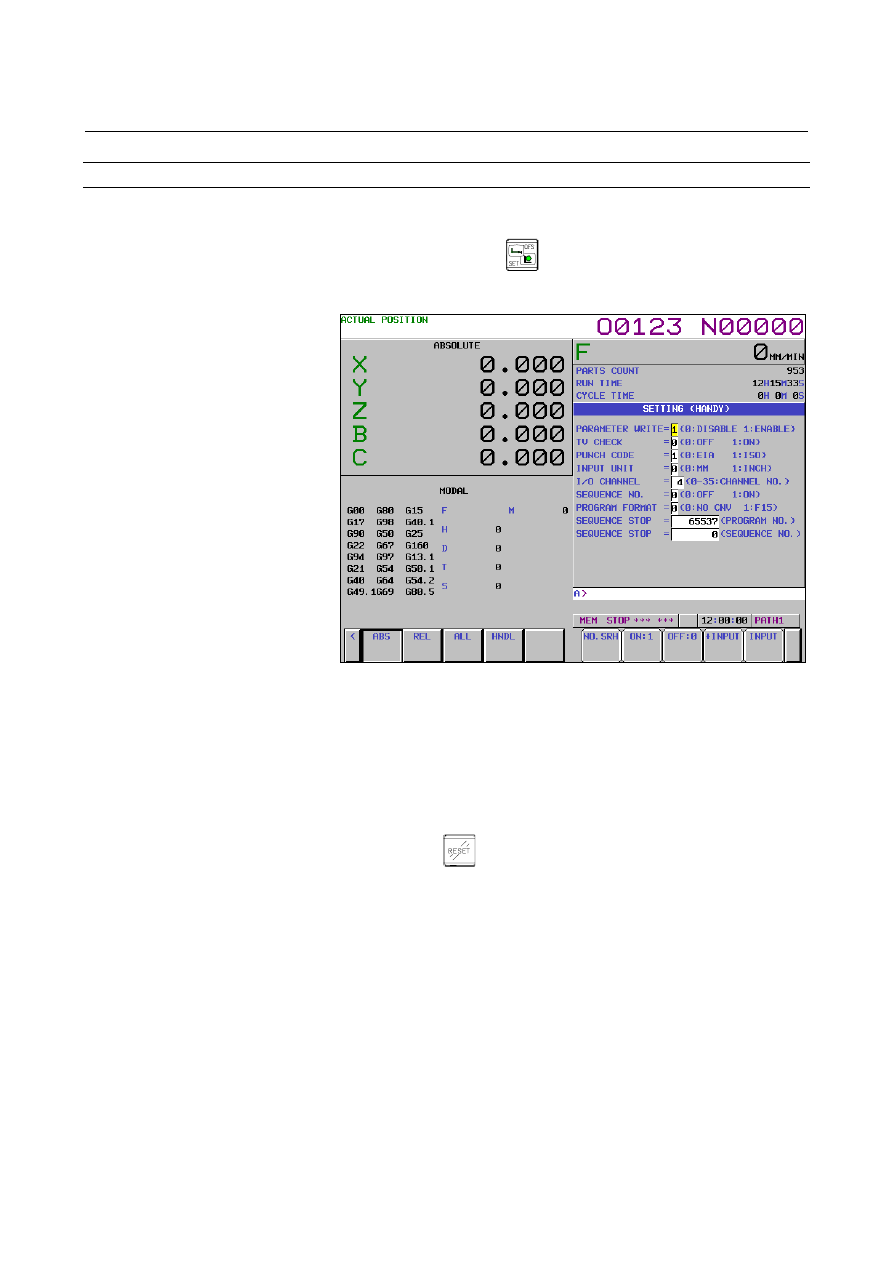
Press soft key [SETTING] to display the setting screen. 


Fig. 12.4.1 (b) SETTING screen (10.4-inch) 


Move the cursor to PARAMETER WRITE using cursor keys. 

Press soft key [(OPRT)], then press [ON:1] to enable parameter 
writing. 
At this time, the CNC enters the alarm state SW0100. 

After setting parameters, return to the setting screen. Move the 
cursor to PARAMETER WRITE and press soft key [(OPRT)] , 
then press [OFF:0]. 

7 Press 

the 

  key to release the alarm condition. 


When an alarm PW0000 occurred, however, it is not released 
unless the power is turned off and back on. 


B-63944EN/03

 OPERATION 

12.SETTING AND DISPLAYING DATA


- 1725 - 

Explanation 
  - Setting parameters with external input/output devices 

See III-8 for setting parameters with external input/output devices 
such as the memory card. 
 

  - Parameters that require turning off the power 

Some parameters are not effective until the power is turned off and on 
again after they are set. Setting such parameters causes alarm PW0000. 
In this case, turn off the power, then turn it on again. 
 

 - Parameter list 

Refer to the Parameter Manual (B-63950EN) for the parameter list. 
 

 - Setting data 

Some parameters can be set on the setting screen if the parameter list 
indicates "Setting entry is acceptable". Setting 1 for PARAMETER 
WRITE is not necessary when these parameters are set on the setting 
screen. 

12.SETTING AND DISPLAYING DATA

 OPERATION 

B-63944EN/03


- 1726 - 

12.4.2 

Displaying and Setting Pitch Error Compensation Data 

 
If pitch error compensation data is specified, pitch errors of each axis 
can be compensated in detection unit per axis. 
Pitch error compensation data is set for each compensation point at the 
intervals specified for each axis. The origin of compensation is the 
reference position to which the tool is returned. 
The pitch error compensation data is set according to the 
characteristics of the machine connected to the NC. The content of 
this data varies according to the    machine model. If it is changed, the 
machine accuracy is reduced. In principle, the end user must not alter 
this data. 
Pitch error compensation data can be set with external devices such as 
the memory card (see Chapter III-8). Compensation data can also be 
written directly with the MDI panel. 
The following parameters must be set for pitch error compensation. 
Set the pitch error compensation value for each pitch error 
compensation point number set by these parameters. 
In the following example, 33 is set for the pitch error compensation 
point at the reference position. 


1

2

3

33

32

31

34

35

36 37 

Compensation number 
parameter for the reference 
position (No. 3620) 

Compensation number 
parameter for the 
compensation point having 
the largest value (No. 
3622)

-1

-2

Compensation number parameter for
the compensation point having the
smallest value (No. 3621) 

Compensation 
position number 

Compensation 
value to be set

3

3

3

3

31

3

3

-3

+1

+1

+1

+2

-1 -3 

Reference position 

Compensation 
interval parameter
(No. 3624) 

Compensation magnification 
parameter (No. 3623) 

Pitch error compensation value (absolute value) 


Number of the pitch error compensation point at the reference 
position (for each axis): Parameter No. 3620 

  Number of the pitch error compensation point having the 

smallest value (for each axis): Parameter No. 3621 


Number of the pitch error compensation point having the largest 
value (for each axis): Parameter No. 3622 

  Pitch error compensation magnification (for each axis):  

Parameter No. 3623 


Interval of the pitch error compensation points (for each axis):  
Parameter No. 3624 

B-63944EN/03

 OPERATION 

12.SETTING AND DISPLAYING DATA


- 1727 - 


Travel distance per revolution of pitch error compensation of the 
rotary axis type (for each axis): Parameter No. 3625 


  - Bi-directional pitch error compensation 

The bi-directional pitch error compensation function allows 
independent pitch error compensation in different travel directions.  
(When the movement is reversed, compensation is automatically 
carried out as in a backlash.) 
To use this function, specify pitch error compensation for each travel 
direction, that is, separately for the positive and negative directions of 
a movement. 
When using bi-directional pitch error compensation (setting bit 0 
(BDPx) of parameter No. 3605 to 1), specify the following parameters 
in addition to the pitch error compensation parameter. 


Number of the pitch error compensation point at the negative end 
(for travel in the positive direction, for each axis): Parameter No. 
3621 


Number of the pitch error compensation point at the positive end 
(for travel in the positive direction, for each axis): Parameter No. 
3622 


Number of the pitch error compensation point at the negative end 
(for travel in the negative direction, for each axis): Parameter No. 
3626 


Pitch error compensation in the reference position when moving 
to the reference position from opposite to the reference position 
return direction (for each axis): Parameter No. 3627 


Procedure for displaying and setting the pitch error compensation data 


Procedure 

Set the following parameters: 

  Number of the pitch error compensation point at the 

reference position (for each axis): Parameter No. 3620 


Number of the pitch error compensation point having the 
smallest value (for each axis): Parameter No. 3621 


Number of the pitch error compensation point having the 
largest value (for each axis): Parameter No. 3622 

  Pitch error compensation magnification (for each axis): 

Parameter No. 3623 


Interval of the pitch error compensation points (for each 
axis): Parameter No. 3624 


Travel distance per revolution of pitch error compensation 
of the rotary axis type (for each axis): Parameter No. 3625 


When using bi-directional pitch error compensation (setting bit 0 
(BDPx) of parameter No. 3605 to 1), specify the following 
parameters in addition to the pitch error compensation parameter. 

  Number of the pitch error compensation point at the 

negative end (for travel in the positive direction, for each 
axis): Parameter No. 3621 

12.SETTING AND DISPLAYING DATA

 OPERATION 

B-63944EN/03


- 1728 - 

  Number of the pitch error compensation point at the 

positive end (for travel in the positive direction, for each 
axis): Parameter No. 3622 

  Number of the pitch error compensation point at the 

negative end (for travel in the negative direction, for each 
axis): Parameter No. 3626 

  Pitch error compensation in the reference position when 

moving to the reference position from opposite to the 
reference position return direction (for each axis):  
Parameter No. 3627 

Press function key 

Press the continuous menu key 

, then press chapter selection 

soft key [PITCH ERROR]. The following screen is displayed: 


Fig. 12.4.2 (a) PITCH ERROR COMPENSATION screen (10.4-inch) 


Move the cursor to the compensation point number to be set in 
either of the following ways: 


Enter the compensation point number and press the soft key 
[NO.SRH]. 


Move the cursor to the compensation point number using 

the page keys, 

 and 

, and cursor keys, 

, and 

Enter a value with numeric keys and press soft key [INPUT]. 


B-63944EN/03

 OPERATION 

12.SETTING AND DISPLAYING DATA


- 1729 - 

12.4.3 

Displaying and Setting Three-Dimensional Error 

Compensation Data 

 
In ordinary pitch error compensation, compensation is applied to a 
specified compensation axis (single axis) by using its position 
information. For example, pitch error compensation is applied to 
X-axis by using the position information of X-axis. 
Three-dimensional error compensation is a function that adjusts the 
current position by calculating compensation data (for three axes) 
from the compensation amounts at surrounding compensation points 
(eight points) on the basis of the interior division ratio in the 
compensation area (rectangular parallelepiped) containing the current 
position on up to three compensation axes. 
 

  - Calculation of compensation 

Three-dimensional error compensation is calculated as follows. 


Suppose three compensation axes to be X, Y, and Z (three basic axes) 
and the coordinates of the current position be P (Px, Py, Pz). consider 
a compensation space (rectangular parallelepiped) containing P. Let its 
vertexes be P1, P2, …, and P8 and the compensation values for the 
individual axes at the individual vertexes be Cnx, Cny, and Cnz 
(where n is a number between 1 and 8). 
Let the interior division ratio on X-axis at P be x. Here, x is 
standardized in the range of 0 to 1 as follows: 

P1x and P2x are the X coordinates of P1 and P2. The interior division 
ratios on Y and Z-axes are determined in the same way. 

|

1

2

|

|

1

|

x

P

x

P

x

P

Px

x

=

P4 [

C4x, C4y, C4z

]

P (

Px, Py, Pz)

P5 [

C5x, C5y, C5z

]

P6 [

C6x, C6y, C6z

]

P1 [

C1x, C1y, C1z

]

P2 [

C2x, C2y, C2z

]

P3 [

C3x, C3y, C3z

]

P8 [

C8x, C8y, C8z

]

P7 [

C7x, C7y, C7z

]

x


y

z

12.SETTING AND DISPLAYING DATA

 OPERATION 

B-63944EN/03


- 1730 - 

The compensation amount Cx for X-axis at P is determined as 
follows: 

 
The compensation amount Cy and Cz on Y and Z-axes are determined 
in the same way. 
 
The actual compensation amounts are the calculated compensation 
amounts multiplied by the compensation magnifications (Parameter 
No.10809 to 10811). 
 

  - Number of compensation points 

Up to 15625 compensation points (up to 25 points per axis) can be set. 
The numbers of compensation points on the individual axes are set for 
parameters No.10803 to 10805. The ordering of the compensation 
point numbers in the compensation space is as follows. 


Max1

×

Max2

×

Max3


Max1

×

Max2

×

(Max3-1

+1 


… 
… 

Max1

×

Max2

×

Max1

×

Max2

×

2


Max1

×

Max2 

… 

… 

Max1

×

Max2+1


Max1

×

3


Max1

×

 1   2   3      

…………………           Max1 


Max1

×

Max2+Max1


z

y

x

x

C

z

y

x

x

C

z

y

x

x

C

z

y

x

x

C

z

y

x

x

C

z

y

x

x

C

z

y

x

x

C

z

y

x

x

C

Cx

×

×

×

+

×

×

×

+

×

×

×

+

×

×

×

+

×

×

×

+

×

×

×

+

×

×

×

+

×

×

×

=

)

1

(

8

7

)

1

(

6

)

1

(

)

1

(

5

)

1

(

)

1

(

4

)

1

(

3

)

1

(

)

1

(

2

)

1

(

)

1

(

)

1

(

1

Max1 : Number of compensation points on the first axis (up to 25) 
Max2 : Second axis (up to 25) 
Max3 : Third axis (up to 25) 

(Third compensation axis)

(Second compensation axis)

(First compensation axis)

B-63944EN/03

 OPERATION 

12.SETTING AND DISPLAYING DATA


- 1731 - 

Displaying and setting three-dimensional error compensation data 

Procedure 

Set the following parameters: 

  First compensation axis for three-dimensional error 

compensation : Parameter No. 10800 

  Second compensation axis for three-dimensional error 

compensation : Parameter No. 10801 

  Third compensation axis for three-dimensional error 

compensation : Parameter No. 10802 


Number of compensation points for three-dimensional error 
compensation (first compensation axis) 
Parameter No. 10803 


Number of compensation points for three-dimensional error 
compensation (second compensation axis) 
Parameter No. 10804 


Number of compensation points for three-dimensional error 
compensation (third compensation axis) 
Parameter No. 10805 


Compensation point number of the reference position for 
three-dimensional error compensation (first compensation 
axis) : Parameter No. 10806 


Compensation point number of the reference position for 
three-dimensional error compensation (second 
compensation axis) : Parameter No. 10807 


Compensation point number of the reference position for 
three-dimensional error compensation (third compensation 
axis) : Parameter No. 10808 

  Magnification for three-dimensional error compensation 

(first compensation axis) : Parameter No. 10809 

  Magnification for three-dimensional error compensation 

(second compensation axis) : Parameter No. 10810 

  Magnification for three-dimensional error compensation 

(third compensation axis) : Parameter No. 10811 

  Compensation interval for three-dimensional error 

compensation (first compensation axis) 
Parameter No. 10812 

  Compensation interval for three-dimensional error 

compensation (second compensation axis) 
Parameter No. 10813 

  Compensation interval for three-dimensional error 

compensation (third compensation axis) 
Parameter No. 10814 


Press function key 


Content      ..     219      220      221      222     ..