FANUC Series 30i/300i/300is-MODEL A. Machining Center System. User's manual - page 220
 

  Index      Manuals     FANUC Series 30i/300i/300is-MODEL A. Machining Center System. User's manual (B-63944EN/03)


Search            copyright infringement  


Content      ..     218      219      220      221     ..


FANUC Series 30i/300i/300is-MODEL A. Machining Center System. User's manual - page 220


12.SETTING AND DISPLAYING DATA

 OPERATION 

B-63944EN/03


- 1716 - 

12.3.29 

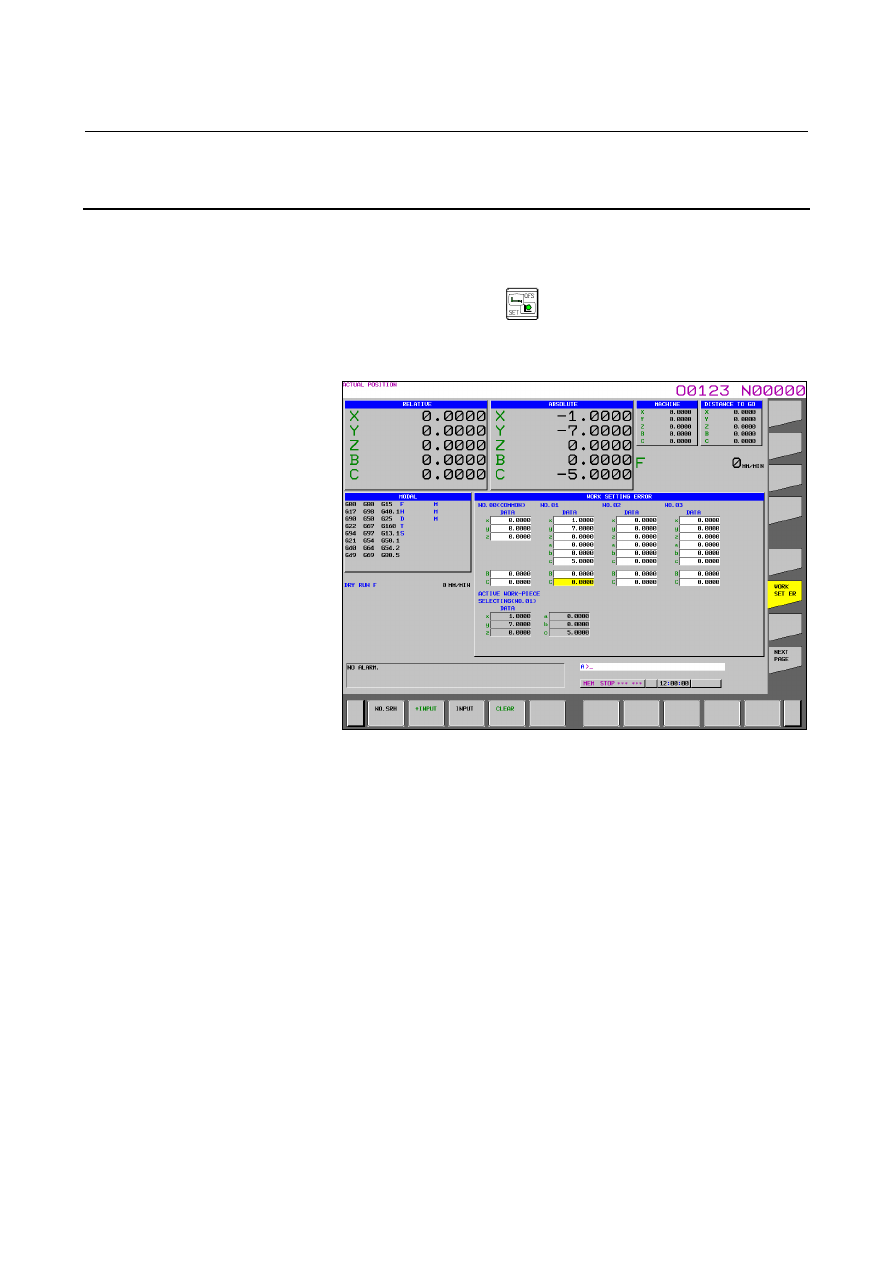
Displaying and Setting Workpiece Setting Error 

Compensation Data (15-inch Display Unit) 

 
An amount of error used in workpiece setting error compensation can 
be


set on the workpiece setting error screen.


The workpiece setting error screen is displayed as follows:


Press function key 

Press vertical soft key [WORK SET ER].   


The workpiece setting error screen appears. 


Fig. 12.3.29 (a)


Workpiece setting error screen (15-inch) 

 
Up to 7 sets (No. 01 to No. 07) of different amounts of workpiece 
setting error can be specified.    In addition, it is possible to specify an 
amount of error (No. 00 (COMMON)) to be added to an error in the 7 
sets in common.


The X-direction error 

x, Y-direction error 

y, and Z-direction error 

z are specified, respectively, in the x, y, and z fields.    The rotational 

errors 

a, 

b, and 

c are specified, respectively, in the a, b, and c 

fields. 
Table rotation axis positions 1 and 2 are specified in the fields under 
the a, b, and c fields (C and B in the figure). 
Rotation axis names specified in parameter Nos. 19681 and 19686 are 
displayed in the axis name fields. 
Table rotation axis positions 1 and 2 are specified for rotation axes.   
No position must be specified for axes (including virtual axes) other 
than table rotation axes.    So, no such item is displayed for setting. 
Table rotation axis position setting items are displayed under the 
following conditions. 

B-63944EN/03

 OPERATION 

12.SETTING AND DISPLAYING DATA


- 1717 - 

  It must have been correctly specified which axis is a table 

rotation axis. 


If parameter No. 19680 = 12 (table rotation type), axis numbers 
must have been specified correctly in parameter Nos. 19681 and 
19686. 


If parameter No. 19680 = 21 (mixed type), an axis number must 
have been specified correctly in parameter No. 19686. 


Bit 0 of parameter No. 1006 must be 1 (rotation axis) for the axes 
specified above. 


The following soft key can be used in data setting. 


After a workpiece setting error number you want to display is 
entered, pressing horizontal soft key [NO.SRH] causes a setting 
screen for the target workpiece setting error to appear. 


After a number is entered, pressing horizontal soft key [+INPUT] 
causes the number to be added. 


After a number is entered, pressing horizontal soft key [INPUT] 
causes the number to be set. 


Pressing horizontal soft key [CLEAR] causes the next soft key to 
appear. 


After a workpiece setting error number to be deleted is entered, 
pressing horizontal soft key [NO.] deletes the data corresponding 
to the workpiece setting error number. 


Pressing horizontal soft key [ALL] deletes data for all workpiece 
setting error numbers. 

12.SETTING AND DISPLAYING DATA

 OPERATION 

B-63944EN/03


- 1718 - 

12.3.30 

Displaying and Setting Pattern Data Inputs 

  (15-inch Display Unit) 

 
Described below are a method for displaying machining menus 
(pattern menus) created by machine tool builders and a method for 
setting them.    The descriptions are based on an example.    For actual 
pattern menus and pattern data, refer to manuals released by respective 
machine tool builders. 
 

Displaying pattern data and pattern menus 


Given below is a procedure for displaying pattern menus.


Press function key 

.


Press vertical soft key [NEXT PAGE] several times. 

Press vertical soft key [PATTERN MENU].   


The pattern menu screen shown below appears.


Fig. 12.3.30 (a)


Pattern menu screen (15-inch)


B-63944EN/03

 OPERATION 

12.SETTING AND DISPLAYING DATA


- 1719 - 

On this screen, a pattern to be used can be selected. 
The following two methods can be used to select patterns. 


Using the cursor 


Move the cursor to a pattern name you want to select, using 
cursor key 

 or 

, and then press soft key [SELECT] or 


Specifying a pattern number 


Enter a number displayed at the left side of a pattern name, and 
press soft key [SELECT] or 

The custom macro screen (pattern data screen) shown below appears. 


Fig. 12.3.30 (b)


Custom macro screen (pattern data) (15-inch)


Enter the necessary pattern data, and press


After entering all necessary data, select the MEMORY mode and 
press the cycle start button.    Machining begins. 


Explanation 

  - Explanations about the pattern menu screen 
    HOLE PATTERN 

An arbitrary character string consisting of 12 or less characters can be 
displayed as a menu title. 
 

    BOLT HOLE 

An arbitrary character string consisting of 10 or less characters can be 
displayed as a pattern name. 


Machine tool builders should program menu title and pattern name 
character strings, using custom macros, and save them in program 
memory. 

12.SETTING AND DISPLAYING DATA

 OPERATION 

B-63944EN/03


- 1720 - 


-  Explanations about the custom macro screen (pattern data screen) 
    BOLT HOLE 

An arbitrary character string consisting of 12 or less characters can be 
displayed as a pattern data title. 
 

    TOOL. 

An arbitrary character string consisting of 10 or less characters can be 
displayed as a variable name. 
*BOLT HOLE* 
The comment text consists of nine 12-character blocks, or the 
comment can be up to 12 lines (10.4-inch display) or 8 lines (7.2 or 
8.4-inch display) with one block counted as one line. 
 
Machine tool builders should program variable name and comment 
text character strings, using custom macros, and save them in program 
memory. 
 

B-63944EN/03

 OPERATION 

12.SETTING AND DISPLAYING DATA


- 1721 - 

12.4 

SCREENS DISPLAYED BY FUNCTION KEY 


When the CNC and machine are connected, parameters must be set to 
determine the specifications and functions of the machine in order to 
fully utilize the characteristics of the servo motor or other parts. 
This chapter describes how to set parameters on the MDI panel. 
Parameters can also be set with external input/output devices such as 
the memory card (see III-8). 
In addition, pitch error compensation data used for improving the 
precision in positioning with the ball screw on the machine can be set 
or displayed by the operations under function key 

See III-7 for the diagnosis screens displayed by pressing function key 

Section 12.4, "SCREENS DISPLAYED BY FUNCTION KEY 

", consists of the following subsections: 


―――――

  Screens of a 7.2/8.4/10.4-inch display unit 

12.4.1  Displaying and Setting Parameters ....................................1723 
12.4.2  Displaying and Setting Pitch Error Compensation Data....1726 
12.4.3  Displaying and Setting Three-Dimensional Error 

Compensation Data ............................................................1729 

12.4.4 Servo Parameters................................................................1733 
12.4.5 Servo Tuning......................................................................1734 
12.4.6 Spindle Setting ...................................................................1735 
12.4.7 Spindle Tuning...................................................................1736 
12.4.8 Spindle Monitor .................................................................1737 
12.4.9  Color Setting Screen ..........................................................1738 
12.4.10 Machining Parameter Tuning.............................................1741 
12.4.11 Displaying Memory Data...................................................1749 
12.4.12 Parameter Tuning Screen ...................................................1751 
12.4.13 Periodic Maintenance Screen.............................................1768 
12.4.14 System Configuration Screen.............................................1776 
12.4.15 Overview of the History Function .....................................1779 

―――――

  Screens of a 15-inch display unit   

12.4.16 Displaying and Setting Parameters (15-inch Display Unit)1802 
12.4.17 Displaying and Setting Pitch Error Compensation Data 

(15-inch Display Unit) .......................................................1805 

12.4.18 Displaying and Setting Three-Dimensional Error 

Compensation Data (15-inch Display Unit).......................1808 

12.4.19 Servo Parameters (15-inch Display Unit) ..........................1812 
12.4.20 Servo Tuning (15-inch Display Unit) ................................1813 
12.4.21 Spindle Setting (15-inch Display Unit)..............................1814 
12.4.22 Spindle Tuning (15-inch Display Unit) .............................1815 
12.4.23 Spindle Monitor (15-inch Display Unit)............................1816 
12.4.24 Color Setting Screen (15-inch Display Unit).....................1817 
12.4.25 Machining Parameter Tuning (15-inch Display Unit) .......1820 

12.SETTING AND DISPLAYING DATA

 OPERATION 

B-63944EN/03


- 1722 - 

12.4.25 Machining Parameter Tuning (15-inch Display Unit) .......1820 
12.4.26 Displaying Memory Data (15-inch Display Unit) .............1828 
12.4.27 Parameter Tuning Screen (15-inch Display Unit)..............1830 
12.4.28 Periodic Maintenance Screen (15-inch Display Unit) .......1847 
12.4.29 System Configuration Screen (15-inch Display Unit) .......1855 
12.4.30 Overview of the History Function (15-inch Display Unit) 1858 
 

B-63944EN/03

 OPERATION 

12.SETTING AND DISPLAYING DATA


- 1723 - 

Screens of a 7.2/8.4/10.4-inch display unit 


12.4.1 

Displaying and Setting Parameters 

 
When the CNC and machine are connected, parameters are set to 
determine the specifications and functions of the machine in order to 
fully utilize the characteristics of the servo motor. The setting of 
parameters depends on the machine. Refer to the parameter list 
prepared by the machine tool builder. 
Normally, the user need not change parameter setting. 


Procedure for displaying and setting parameters 

Procedure 

1  Set 1 for PARAMETER WRITE to enable writing.  See the 

procedure for enabling/disabling parameter writing described 
below. 

Press function key 

3  Press chapter selection soft key [PARAM] to display the 

parameter screen. 


Fig. 12.4.1 (a) PARAMETER screen (10.4-inch) 

Move the cursor to the parameter number to be set or displayed 
in either of the following ways:   


Enter the parameter number and press soft key [NO.SRH] . 


Move the cursor to the parameter number using the page 

keys, 

 and 

, and cursor keys, 

, and 

To set the parameter, enter a new value with numeric keys and 
press soft key [INPUT]. The parameter is set to the entered value 
and the value is displayed. 

Set 0 for PARAMETER WRITE to disable writing. 


Content      ..     218      219      220      221     ..