FANUC Series 30i/300i/300is-MODEL A. Machining Center System. User's manual - page 222
 

  Index      Manuals     FANUC Series 30i/300i/300is-MODEL A. Machining Center System. User's manual (B-63944EN/03)


Search            copyright infringement  


Content      ..     220      221      222      223     ..


FANUC Series 30i/300i/300is-MODEL A. Machining Center System. User's manual - page 222


12.SETTING AND DISPLAYING DATA

 OPERATION 

B-63944EN/03


- 1732 - 

3  Press the continuous menu key 

 several times, then press 

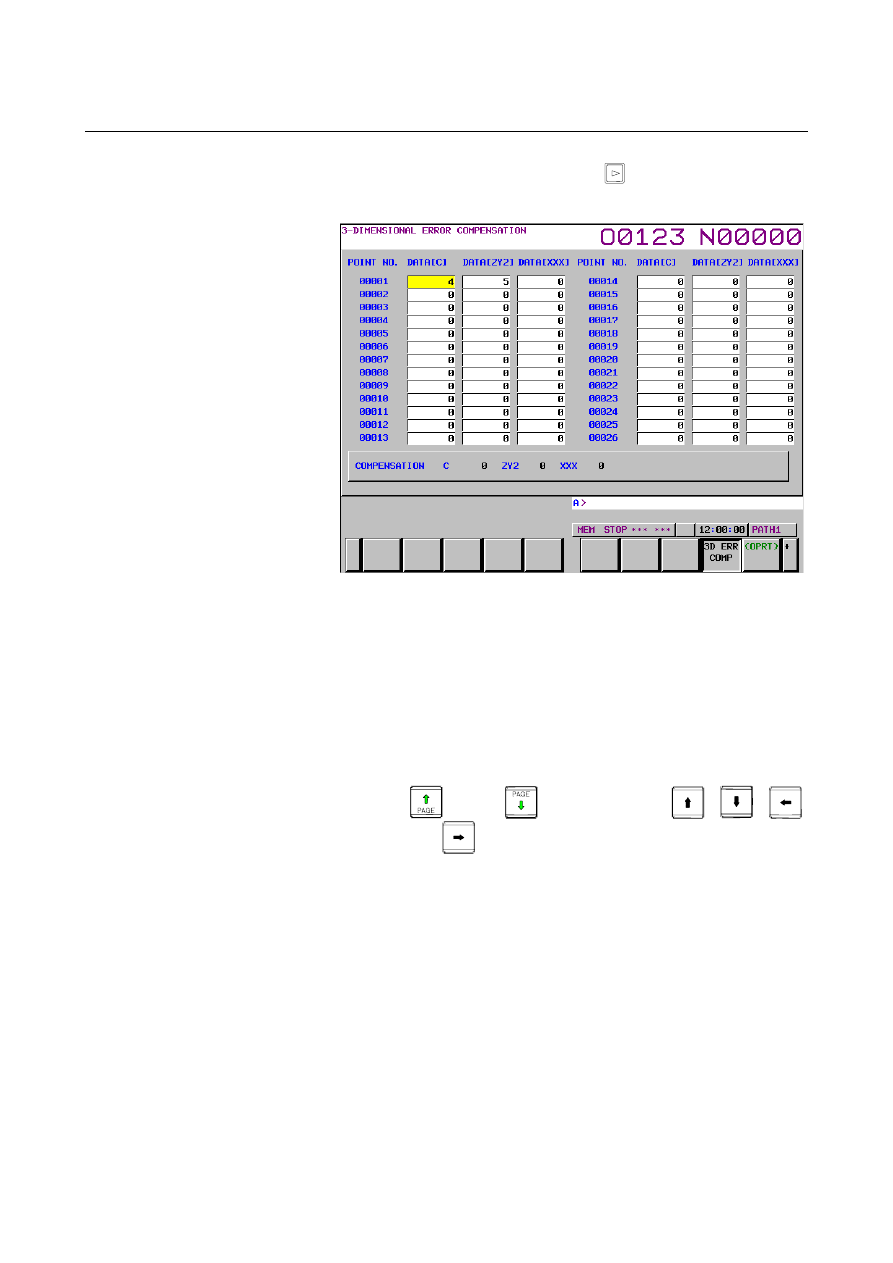
chapter selection soft key [3D ERR COMP].  The following 
screen appears: 


Fig. 12.4.3 (a) 3-DIMENSIONAL ERROR COMPENSATION screen 

(10.4-inch) 

 
4  Move the cursor to the position of the compensation point 

number you want to set using either of the following methods: 


Select the MDI mode. 


Set bit 0 (PWE) of parameter No. 8900 to 1. 


Enter a compensation point number and press soft key [NO. 
SRH]. 

  Move the cursor to the compensation point number or 

compensation axis you want to set by pressing page keys 

 and/or 

, and cursor keys 

and 

5  Enter compensation data in detection units.  The valid data 

range is from -128 to 127. 


B-63944EN/03

 OPERATION 

12.SETTING AND DISPLAYING DATA


- 1733 - 

12.4.4 

Servo Parameters 

 
This subsection describes the initialization of digital servo parameters 
performed, for example, at the time of field tuning of the machine 
tool. 
 

Procedure for servo parameter setting 

Procedure 

Turn on the power in the emergency stop state. 

2  Set bit 0 (SVS) of parameter No. 3111 to 1 to display servo 

setting and tuning screens. 

Press function key 

, continuous menu key 

, then soft 

key [SERVO PARAM]. 

Press soft key [SERVO PARAM] to select the servo parameter 
screen. 


The following screen appears: 


Fig. 12.4.4 (a) Servo parameter setting screen (10.4-inch) 

 
5  With the page keys and cursor keys, move the cursor to the 

position of data to be set or modified. 

Key in a desired value then press soft key [INPUT]. 


12.SETTING AND DISPLAYING DATA

 OPERATION 

B-63944EN/03


- 1734 - 

12.4.5 

Servo Tuning 

 
Data related to servo tuning is displayed and set. 
 

Procedure for servo tuning 

Procedure 

Turn on the power in the emergency stop state. 

2  Set bit 0 (SVS) of parameter No. 3111 to 1 to display servo 

setting and tuning screens. 

Press function key 

, continuous menu key 

, then soft 

key [SERVO PARAM]. 

Press soft key [SERVO TUNE] to select the servo tuning screen. 

Use the cursor and page keys to enter necessary data for initial 
setting. The following screen appears: 


Fig. 12.4.5 (a) Servo tuning screen (10.4-inch) 

 
6  With the page keys and cursor keys, move the cursor to the 

position of data to be set or modified. 

Key in a desired value then press soft key [INPUT]. 


B-63944EN/03

 OPERATION 

12.SETTING AND DISPLAYING DATA


- 1735 - 

12.4.6 

Spindle Setting 

 
Parameters related to spindles are set and displayed.    In addition to 
the parameters, related data can be displayed.  Screens for spindle 
setting, spindle tuning, and spindle monitoring are provided. 
 

Setting spindle parameters 

Procedure 

Set bit 1 (SPS) of parameter No. 3111 to 1 to display spindle 
setting and tuning screens. 

Press function key 

, continuous menu key 

, then soft 

key [SPINDL SETING]. 

Press soft key [SPINDL SETING] to select the spindle setting 
screen. 


The following screen appears: 


Fig. 12.4.6 (a) Spindle setting screen (10.4-inch) 

 
4  With the page keys and cursor keys, move the cursor to the 

position of data to be set or modified. 

Key in a desired value then press soft key [INPUT]. 


12.SETTING AND DISPLAYING DATA

 OPERATION 

B-63944EN/03


- 1736 - 

12.4.7 

Spindle Tuning 

 
Spindle tuning data is displayed and set. 
 

Setting for spindle tuning 

Procedure 

Set bit 1 (SPS) of parameter No. 3111 to 1 to display spindle 
setting and tuning screens. 

Press function key 

, continuous menu key 

, then soft 

key [SPINDL SETING]. 

Press soft key [SPINDL TUNE] to select the spindle tune screen. 

The following screen appears: 


Fig. 12.4.7 (a) Spindle tuning screen (10.4-inch) 

 
5  With the page keys and cursor keys, move the cursor to the 

position of data to be set or modified. 

Key in a desired value then press soft key [INPUT]. 


B-63944EN/03

 OPERATION 

12.SETTING AND DISPLAYING DATA


- 1737 - 

12.4.8 

Spindle Monitor 

 
Spindle-related data is displayed. 
 

Displaying the spindle monitor 

Procedure 

Set bit 1 (SPS) of parameter No. 3111 to 1 to display spindle 
setting and tuning screens. 

Press function key 

, continuous menu key 

, then soft 

key [SPINDL SETING]. 

Press soft key [SP.MON] to select the spindle monitor screen. 

The following screen appears: 


Fig. 12.4.8 (a) Spindle monitor screen (10.4-inch) 

12.SETTING AND DISPLAYING DATA

 OPERATION 

B-63944EN/03


- 1738 - 

12.4.9 

Color Setting Screen 

 
Screen colors can be set on the color setting screen. 
 

Displaying the color setting screen 

Procedure 

Press function key 

Press the continuous menu key 

  several times to display soft 

key [COLOR]. 

Press soft key [COLOR] to display the color setting screen. 


Fig. 12.4.9 (a) Color setting screen (10.4-inch) 


B-63944EN/03

 OPERATION 

12.SETTING AND DISPLAYING DATA


- 1739 - 

Procedure for operating the color setting screen 

  - Modifying the color (color palette values) 

Press soft key [(OPRT)]. The soft key display changes to the 
following operation soft keys: 


Move the cursor to a color number whose color palette values are 
to be modified. 
The current color palette value set for each primary color is 
displayed. 

Select a primary color whose setting is to be modified, with the 
corresponding operation soft key [RED], [GREEN], or [BLUE]. 
More than one primary color can be selected at the same time. 
Each time operation soft key [RED], [GREEN], or [BLUE] is 
pressed, the operation soft key toggles between selection and 
deselection. 
(When operation soft keys [RED], [GREEN], and [BLUE] are 
not displayed, press the rightmost soft key to display the 
operation soft keys.) 

Select operation soft key [BRIGHT] or [DARK] to modify the 
brightness of the selected prime color(s). 


  - Storing the color (color palette values) 

The set color palette values can be stored. 

Press operation soft key [COLOR1], [COLOR2], or [COLOR3] 
to select a storage area. 
(When operation soft keys [COLOR1], [COLOR2], and 
[COLOR3] are not displayed, press the rightmost soft key to 
display the operation soft keys.) 


COLOR1  

Standard color data parameters Nos. 6581 to 6595 

COLOR2  

Parameters Nos. 10421 to 10435 

COLOR3  

Parameters Nos. 10461 to 10475 

Press operation soft key 

[

MEMORY

]

. The operation soft key 

display switches to the following: 


3  Pressing operation soft key [EXEC] stores the current color 

palette settings in the selected area. 
Pressing operation soft key [CAN] or the leftmost key does not 
store the current color palette settings in the selected area. 


Content      ..     220      221      222      223     ..