FANUC Series 30i/300i/300is-MODEL A. Machining Center System. User's manual - page 214
 

  Index      Manuals     FANUC Series 30i/300i/300is-MODEL A. Machining Center System. User's manual (B-63944EN/03)


Search            copyright infringement  


Content      ..     212      213      214      215     ..


FANUC Series 30i/300i/300is-MODEL A. Machining Center System. User's manual - page 214


12.SETTING AND DISPLAYING DATA

 OPERATION 

B-63944EN/03


- 1668 - 

To end the edit operation, press horizontal soft key [EXIT]. 
This returns the screen display to the conventional tool 
management screen. 


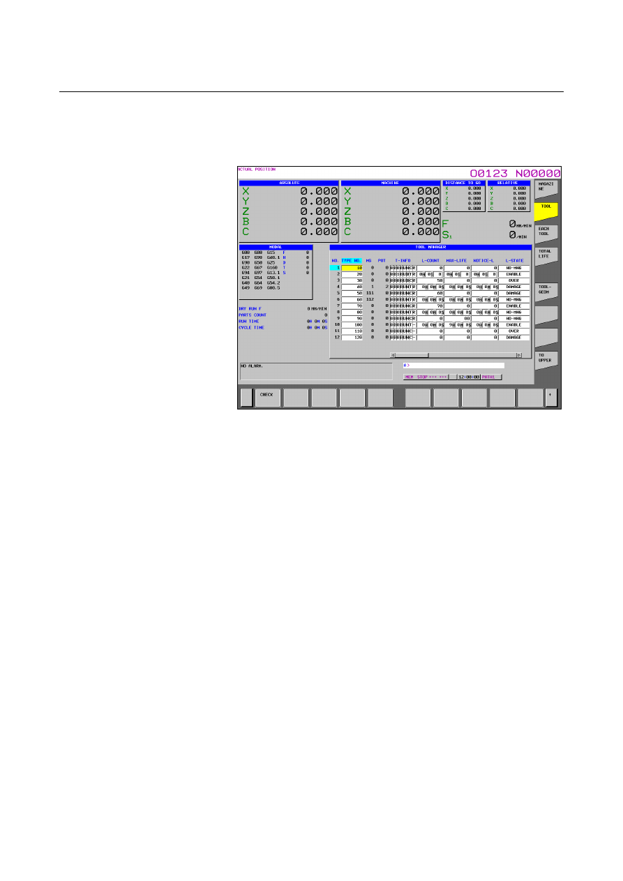
Fig. 12.3.24.2 (b) Tool management data screen (check function) 

(15-inch) 


When horizontal soft key [CHECK] is pressed, if there are tools 
with the same number but with different count types (count and 
time), the cursor moves to the tool type number of the smallest 
tool management number in the tool type numbers and a warning 
message appears. 


The warning messages issued by the check function are shown 
below. 
<1>  For the same type of tools with different count types 
 

L-COUNT TYPE MISMATCH:XXXXXXXX 

<2>  For the same type of tools with the same count type 
 

L-COUNT TYPE MATCH 


B-63944EN/03

 OPERATION 

12.SETTING AND DISPLAYING DATA


- 1669 - 

Explanation 
 - Another method 

Tool management data, customize data, and names set for tool states 
can be input/output also by using external I/O devices. 
See III-8, "DATA I/O". 
 

 - Displayed information 

 Life 

information 


Fig. 12.3.24.2 (c) Tool management data life status screen(15-inch) 

 
NO. 

:  Tool management data numbers are displayed.  These 

numbers can be displayed but cannot be set.  The tool 
management data number of edited data is kept blinking 
until tool management data edit mode ends.  Tool 
management data numbers set or deleted on the magazine 
screen also blink on the tool management screen. 

Type No. :  Tool type numbers are displayed. 
 

  A value from 0 to 99,999,999 can be set. 

MG 

:  The magazine number assigned to each tool is indicated.   

These numbers can be displayed but cannot be set. 

Pot 

:  The pot number assigned to each tool is indicated.  

These numbers can be displayed but cannot be set. 

Tool information: The following five types of information are 

displayed sequentially from the right: 

 Tool management data:  Valid (R)/invalid (-)) 

 Life count type: 

Time (T)/count (C) 

 Tool type: 

Oversize tool (B)/ 
normal tool (N) 

 Data access: 

Locked (L)/unlocked (U) 

 When a tool is not under life management: 


Included in the tools to be searched 
(1)/not included in the tools to be 
searched (0) 

12.SETTING AND DISPLAYING DATA

 OPERATION 

B-63944EN/03


- 1670 - 


NOTE 

1  The tool types and data access information vary 

depending on the specifications defined by the 
machine tool builder. 

2  The same type of tools must have the same life 

count type. 

 
Life counter:  The number of use times/use period of time of each 

tool is indicated. 


Up to 99,999,999 times or 999 hours 59 minutes 59 
seconds can be set. 

Maximum life:  The maximum life value of each tool is indicated. 
 

Up to 99,999,999 times or 999 hours 59 minutes 59 
seconds can be set. 

Noticed life: 

Noticed life value of a tool 


Up to 99,999,999 times or 999 hours 59 minutes 59 
seconds can be set. 

Life state: 

Current tool state 


One of the four states, including invalid (0), present (1, 

2), not present (3), and broken (4), is indicated.    The 
numbers in parentheses are data values used when 
these states are input in MDI. 


 Spindle 

speed/feedrate 


Fig. 12.3.24.2 (d) Tool management data spindle speed/feedrate screen 

(15-inch) 

 
S : Spindle speed. 
    A value from 0 to 99,999 can be set. 
F : Feedrate. 
    A value from 0 to 99,999,999 can be set. 
 

B-63944EN/03

 OPERATION 

12.SETTING AND DISPLAYING DATA


- 1671 - 


Tool offset information 


Fig. 12.3.24.2 (e) Tool management data tool offset screen (15-inch) 


: Tool length compensation number (for machining center 

systems only). 


  A value from 0 to 999 can be set. 

: Cutter compensation number (for machining center systems 

only). 


  A value from 0 to 999 can be set. 

TG  :  Tool geometry compensation number (for lathe systems only). 
 

  A value from 0 to 999 can be set. 

TW  :  Tool wear compensation number (for lathe systems only). 
 

  A value from 0 to 999 can be set. 

The displayed offset data is determined depending on the option 
configuration and parameter settings (bits 1(DCR), 2(DOY), 3(DOB), 
4(DO2), 6(DOT), and 7(DOM) of parameter No. 13202). 


12.SETTING AND DISPLAYING DATA

 OPERATION 

B-63944EN/03


- 1672 - 

 Customize 

information 


Fig. 12.3.24.2 (f) Tool management data customize data screen (15-inch) 

 
Customize 0 

:  Bit-type customize information. 


  For each bit, 1 or 0 can be input. 

Customize 1 to 4 

:  Customize information. Any value from   

-99,999,999 to 99,999,999 can be set. 

Customize 

to 

20 : 

Customize information. These items are 
displayed only when customize data extension 
option (5 to 20) of the tool management 
function is enabled.    Any value from   
-99,999,999 to 99,999,999 can be set. 

Customize 

21 

to 

40 : 

Customize information. These items are 
displayed only when customize data extension 
option (5 to 40) of the tool management 
function is enabled. Any value from   
-99,999,999 to 99,999,999 can be set. 


  - Tool management data number 

Tool management data numbers can optionally be extended to 64, 240, 
or 1000 pairs. The number of tools used can be set in parameter No. 
13220. 
 

 - Edit mode 

To edit data, press horizontal soft key [EDIT] to enter tool 
management data edit mode. 
 

  - Life count override 

When the period of time is set as the tool life count type, the life count 
can be overridden if bit 2 (LFV) of parameter No. 6801 is set to 1.   
Specify an override value by using a switch on the machine operator's 
panel. 
Example)  When cutting is performed for 10 minutes with an override 

of 0.1, one minute is counted in the tool life counter. 

B-63944EN/03

 OPERATION 

12.SETTING AND DISPLAYING DATA


- 1673 - 


  - Tool management extension function 

When tool management extension functions are enabled, you can use 
the following functions in addition to the tool management functions: 


A value with a decimal point can be set as customize data. 


The maximum number of decimal places can be set to 7 by G10 
data input and file read. 


Various types of tool management data can be protected using 
KEY signals. 


An attempt to enter a value to a protected data causes a warning 
message “WRITE PROTECT.” 


Tool life count period selection 


Bit 5 of tool information is used to make a life count period 
selection. 


Item Description 

Data length 

1 byte (flag data) 

#5 

REV 

0: A life count period of 1 sec is used. 
1: A life count period of 8 msec is used. 

Range of count is as follows. 

1sec 

: 0 to 3,599,999 seconds (999 hours 59 minutes 59 seconds) 

8msec 

: 0 to 3,599,992 ms (59 minutes 59 seconds 992 milliseconds) 


12.SETTING AND DISPLAYING DATA

 OPERATION 

B-63944EN/03


- 1674 - 

12.3.24.3 

Each tool data screen (15-inch display unit) 


Each tool data screen 

Procedure 

Press function key 

2  Press vertical soft key [NEXT PAGE] several times and then 

vertical soft key [TOOL MANAGER

]

Press vertical soft key [EACH TOOL]. The each tool data screen 
appears. 


Fig. 12.3.24.3 (a) Each tool data screen (15-inch) 


Explanation 
 - Header 

The following four data items are displayed: NO., TYPE NO., MG, 
and POT. 
When the data table of a tool extends over two or more pages, the 
same header is displayed on these pages. 
 

 - Data table 

The data table shows data items related to a tool at a time. 
The data items are displayed from the upper left to the lower left, the 
upper right, and the lower right in ascending order of screen display 
position numbers specified using the customize function. The number 
of digits displayed for one data item is fixed to 11. 
Up to 24 data items are displayed on one page. (12 data items 

×

 2 

columns) 
When more than 24 data items are set for a tool, the 25th and 
subsequent data items are displayed on the next page. (Up to three 
pages) 

B-63944EN/03

 OPERATION 

12.SETTING AND DISPLAYING DATA


- 1675 - 

When a data item is set as a screen element of the tool management 
data screen twice or more using the tool management data display 
customize function (one of the tool management extension functions), 
only the data item with the smaller display position number is 
displayed. When no value is set for a data item, the field for the data 
item is not displayed and the next data item is displayed. 
 

Key operations 
  - MDI key operations 


Numeral keys   Inputs a numeric value. 


Displays the previous page for the same tool. 


Displays the next page for the same tool. 


Moves the cursor to the previous data item. 

When the cursor is on the top row of the data 
table, it moves to the bottom row of the left 
column. When the cursor is on the first data item, 
it moves to the last data item. 


Moves the cursor to the next data item. 

When the cursor is on the bottom row of the data 
table, it moves to the top row of the right column.   
When the cursor is on the last data item, it moves 
to the first data item. 


Moves the cursor left on the screen. 

When the cursor is on the left column of the data 
table, it moves to the right column on the row 
immediately above. When the cursor is on the 
first data item, it moves to the last data item. 


Moves the cursor right on the screen. 

When the cursor is on the right column of the 
data table, it moves to the left column on the row 
immediately below. When the cursor is on the 
last data item, it moves to the first data item. 


  - Soft key operations 

Horizontal soft key [EDIT] 
 

Enters the management data edit mode. 

Horizontal soft key [NO.SRH] 
 

Displays data with a tool management data number when pressed 
after the tool management data number is entered. 

Horizontal soft key [PREV.TOOL] 
 

Returns to the previous tool management data number. 

Horizontal soft key [NEXT.TOOL] 
 

Proceeds to the next tool management number. 

Horizontal soft key [READ] 
 

Reads data related to the tool management function. 


Can be used only in the standard mode. 


Requires placing the NC in the EDIT mode. 


Content      ..     212      213      214      215     ..