FANUC Series 30i/300i/300is-MODEL A. Machining Center System. User's manual - page 213
 

  Index      Manuals     FANUC Series 30i/300i/300is-MODEL A. Machining Center System. User's manual (B-63944EN/03)


Search            copyright infringement  


Content      ..     211      212      213      214     ..


FANUC Series 30i/300i/300is-MODEL A. Machining Center System. User's manual - page 213


12.SETTING AND DISPLAYING DATA

 OPERATION 

B-63944EN/03


- 1660 - 

4  To display or set real time custom macro variables of which 

values are stored at power-off, press vertical soft key [PERM. 
DATA]. 

5  Move the cursor to the number of a real time custom macro 

variable you want to set using either of the following methods: 


Enter the number of a real time custom macro variable and 
press horizontal soft soft key [NO. SRH]. 


Move the cursor to the number of a real time custom macro 

variable you want to set by pressing page keys 


and/or 

 and cursor keys 

, and/or 

6 Enter 

data. 


Displaying and setting DI/DO variables 

Procedure 

For setting in byte units: 

Press function key 

2  Press vertical soft key [NEXT PAGE] several times and then 

vertical soft key [R.TIME MACRO]. The screen shown below 
appears. 

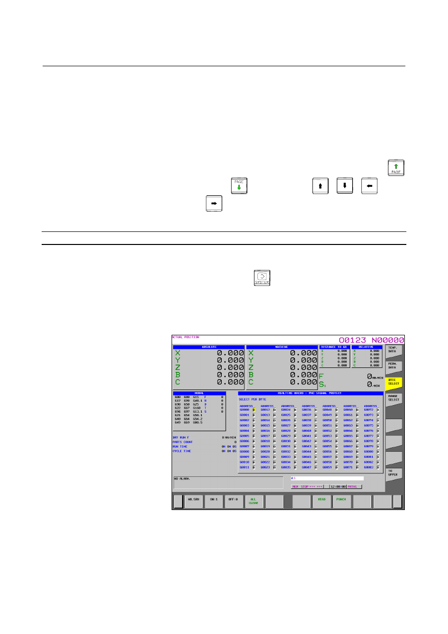
Press vertical soft key [BYTE SELECT]. The following screen 
appears: 


Fig. 12.3.22 (b) BYTE SELECT screen (15-inch) 


B-63944EN/03

 OPERATION 

12.SETTING AND DISPLAYING DATA


- 1661 - 

Move the cursor to the number of a DI/DO variable you want to 
set using either of the following methods: 


Enter the number and press horizontal soft key [NO. SRH]. 


Move the cursor to a desired number by pressing page keys 

 and/or 

 and cursor keys 

and/or 

5 Enter 

data. 

12.SETTING AND DISPLAYING DATA

 OPERATION 

B-63944EN/03


- 1662 - 

12.3.23 

Displaying and Setting the Software Operator’s Panel 

(15-inch Display Unit) 

 
Operations on the MDI panel can substitute for the functions of 
switches on the machine operator’s panel. This means that a mode 
selection, jog feed override selection, and so forth can be made with 
operations on the MDI panel, eliminating the need to use the 
corresponding switches on the machine operator’s panel. 
Jog feed can be performed using numeric keys. 
 

Procedure for displaying and setting the software operator’s panel 

Procedure 

Press function key 

Press vertical soft key [NEXT PAGE] and then vertical soft key 
[OPERAT PANEL]. 

The screen consists of several pages. Press page key 

 or 

  until the desired screen is displayed. 


Fig. 12.3.23 (a) Without the manual handle feed function (15-inch) 


B-63944EN/03

 OPERATION 

12.SETTING AND DISPLAYING DATA


- 1663 - 


Fig. 12.3.23 (b) With the manual handle feed function (15-inch) 


Fig. 12.3.23 (c) (15-inch) 


Move the cursor to the desired switch by pressing cursor key 

 or 

Push the cursor key 

 or 

  to match the mark 

 to an 

arbitrary position and set the desired condition. 

12.SETTING AND DISPLAYING DATA

 OPERATION 

B-63944EN/03


- 1664 - 

Press one of the following arrow keys to perform jog feed. Press 

the 


  key together with an arrow key to perform jog rapid 

traverse. 


Fig. 12.3.23 (d) MDI arrow keys 


Explanation 
 - Valid operations 

The valid operations on the software operator's panel are shown below.   
Whether to use each group can be chosen using parameter No. 7200.   
Those groups that are not used are not displayed on the software 
operator's panel. 
Group1 : Mode selection 
Group2 : Selection of jog feed axis, Manual rapid traverse 
Group3 : Selection of manual pulse generator feed axis, selection of 

manual pulse magnification   

Group4 : Jog federate, federate override, rapid traverse override 
Group5 : Optional block skip, single block, machine lock, dry run 
Group6 : Protect key 
Group7 : Feed hold 
 

  - Screens on which jog feed is valid 

When the LCD indicates other than the software operator's panel 
screen and self-diagnosis screen, jog feed is not conducted even if the 
arrow key is pushed. 
 

  - Jog feed and arrow keys 

The feed axis and direction corresponding to the arrow keys can be set 
with parameters (Nos. 7210 to 7217). 
 

  - General purpose switches 

For the meanings of these switches, refer to the manual issued by 
machine tool builder. 
 

B-63944EN/03

 OPERATION 

12.SETTING AND DISPLAYING DATA


- 1665 - 

12.3.24 

Setting and Displaying Tool Management Data (15-inch 

Display Unit) 

 
The tool management function totally manages tool information 
including tool offsets and tool life information. 
This function provides a magazine screen and tool management screen.   
This subsection explains how to set these screens. 
 

12.3.24.1 

Displaying and setting magazine screen (15-inch display unit) 


Procedure 

1  Press function key 

2  Press vertical soft key [NEXT PAGE] several times and then 

vertical soft key [TOOL MANAGER]. The screen shown below 
appears. 


Fig. 12.3.24.1 (a) ) Tool management magazine screen (15-inch) 


By using the page keys, cursor keys, and horizontal soft keys 
[

] and [

], move the cursor to the pot No. position of the 

magazine for which you want to set or modify data. 
Alternatively, type the number of the tool management data you 
wan to set or modify, and press horizontal soft key [NO. SRH]. 

Press horizontal soft key [EDIT].   

12.SETTING AND DISPLAYING DATA

 OPERATION 

B-63944EN/03


- 1666 - 

To set the tool management data number of a pot, type the tool 
management data number, then press MDI key 

To delete the tool management data number set for a pot, follow 
the steps below. 
<1>  Press horizontal soft key [ERASE].   
<2> Press horizontal soft key [CURDAT]. To delete the tool 

management data numbers registered for all pots, press 
horizontal soft key [ALL]. 

<3>  Press horizontal soft key [EXEC]. Alternatively, type 0. 

To end the edit operation, press horizontal soft key [EXIT]. 
This returns the screen display to the conventional tool 
management screen. 


Explanation 
 - Another method 

Magazine data can be input/output also by using external I/O devices. 
See III-8, "DATA I/O". 

 - Displayed data 

Pot : As many pots as specified in parameter No. 13222, 13227, 

13232, or 13237 (settable for each magazine) are displayed.  
The starting pot number can be set for each magazine in 
parameter No. 13223, 13228, 13233, or 13238. 

NO. :  Tool management data numbers are displayed. 
 

  In the following cases, tools cannot be set in magazines: 

1.  A tool management data number beyond the range from 0 to 

(the number of valid pairs in parameter No. 13220) is set. 

2.  Tool management data is invalid (bit 1 of tool information is 

0). 

3.  The tool management data number to be set is already set for 

another pot. 

Type No. : Tool type numbers corresponding to tool management data 

numbers are displayed. 


  Values cannot be set on this screen. 

Spindle  : The tool management data numbers and tool type numbers 

of spindle positions are displayed. 

Wait 

: The tool management data numbers and tool type numbers 

of wait positions are displayed. 


 - Edit mode 

To edit data, press horizontal soft key [EDIT] to enter tool 
management data edit mode. 
 

  - Tool management data number 

Tool management data numbers can optionally be extended to 64, 240, 
or 1000 pairs. In addition, the number of tools used can be set in 
parameter No. 13220. 
 

  - Display of the spindle positions and wait positions 

The spindle position and wait position can be set for each path. 

B-63944EN/03

 OPERATION 

12.SETTING AND DISPLAYING DATA


- 1667 - 

12.3.24.2 

Displaying and setting tool management screen (15-inch 

display unit) 


Procedure 

Press function key 

2  Press vertical soft key [NEXT PAGE] several times and then 

vertical soft key [TOOL MANAGER]. 

Press vertical soft key [TOOL].   


Fig. 12.3.24.2 (a) Tool management data screen (15-inch) 


By using the page keys, cursor keys, and horizontal soft keys 
[

] and [

], move the cursor to the position of the tool 

information of the tool number for which you want to set or 
modify data. 
Alternatively, type the tool number of the data you want to set or 
modify, and press horizontal soft key [NO. SRH]. 

Press horizontal soft key [EDIT].   

To set tool data, type a desired value, then press MDI key 


To delete tool information, follow the steps below. 
<1>  In step 4, move the cursor to the tool information you want 

to erase. 

<2>  Press horizontal soft key [ERASE].   
<3> Press horizontal soft key [CURDAT]. To delete entire tool 

information, press horizontal soft key [ALL]. 

<4>  Press horizontal soft key [EXEC].   


Content      ..     211      212      213      214     ..