FANUC Series 30i/300i/300is-MODEL A. Machining Center System. User's manual - page 194
 

  Index      Manuals     FANUC Series 30i/300i/300is-MODEL A. Machining Center System. User's manual (B-63944EN/03)


Search            copyright infringement  


Content      ..     192      193      194      195     ..


FANUC Series 30i/300i/300is-MODEL A. Machining Center System. User's manual - page 194


12.SETTING AND DISPLAYING DATA

 OPERATION 

B-63944EN/03


- 1508 - 

NOTE 

1  For existing block modification, if the guidance 

screen is displayed when the cursor is placed in 
the middle of multiple blocks for a command, the 
parameters for the block(s) before the cursor are 
not reflected in the setting and selection items, but 
only the parameters for the block(s) after the 
cursor are reflected. If no data is to be reflected in 
a setting or selection item, the initial value is set in 
the item. 

2  For existing block modification, only the commands 

with parameter-specified axis names are reflected 
in the setting items on the screen. (The values 
specified in data for commands with incorrect axis 
names are not reflected in the setting items.) 


Command data input 


Item for which to enter a value 


Press cursor key 

 or 

  to move the cursor to an item 

you want to set. 


Enter a value, and then press the 

  key or soft key [INPUT]. 


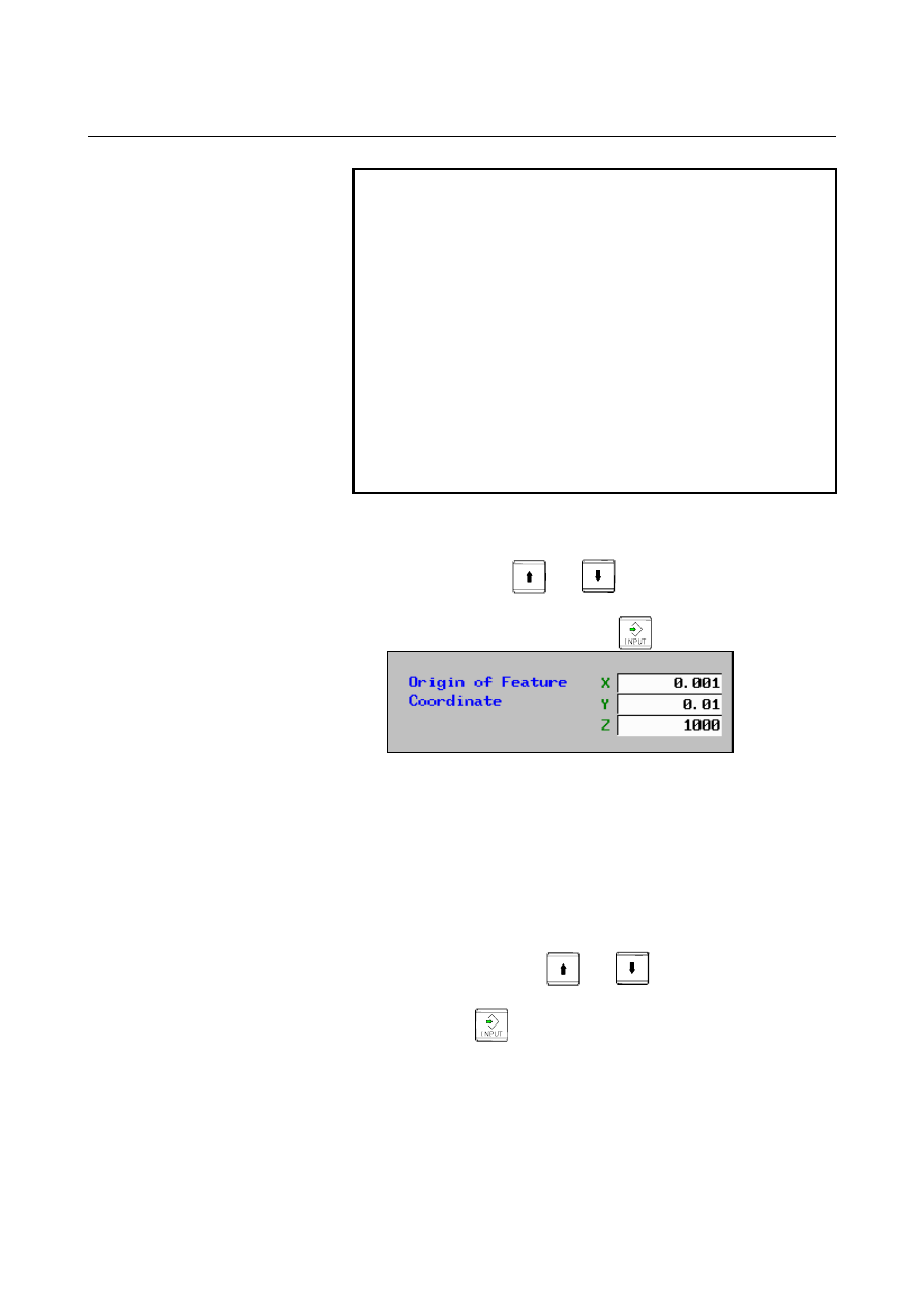
Example) 
 

When the origin of a feature coordinate system is set as 
shown above, addresses X, Y, and Z are specified as 
follows: 


G68.2 X0.001 Y0.01 Z1000 ... 


For two items "Tool Offset Number" and "From TCP to center", 
the state with no command can be set by deleting the specified 
values according to the following procedure. 


Press cursor key 

 or 

  to move the cursor to the 

item "Tool Offset Number" or "From TCP to Center". 

2 Press 

 or soft key [INPUT] without entering 

anything. 


B-63944EN/03

 OPERATION 

12.SETTING AND DISPLAYING DATA


- 1509 - 


Item to be selected from a list 

Press cursor key 

 or 

  to move the cursor to an 

item you want to set. 

Press cursor key 

 or 

  to move the cursor to an 

item you want to select. 


Example)


Order of rotation for Roll-Pitch Yaw angle 


Insertion of a block 

If the guidance screen is displayed when the block at the cursor 
position on the program editing screen does not include a tilted 
working plane command, soft key [INSERT] is displayed on the tilted 
working plane data setting screen. An operation for inserting a tilted 
working plane command block is described below. 
For warnings that may be issued at the time of block insertion, see 
"Limitation". 
 

Press soft key [INSERT].   
The confirmation message "ARE YOU SURE YOU WANT TO 
EXECUTE?" is displayed, and soft keys [YES] and [NO] are 
displayed. 

Press soft key [YES].   
A block is created from the command type and command data 
and then is inserted after the block at the cursor position in the 
program to be edited. After block insertion, the guidance screen 
is closed and the program editing screen is displayed. 
Pressing soft key [NO] takes you back to the tilted working plane 
data setting screen. 


Example) 

G00 X0.;  When the guidance screen is displayed and 

the 3-point specification is selected as a 
command type for block insertion, a created 
block is inserted after the block at the cursor 
position. 

G00 X0.; 
G68.2 P2 Q0... 
G68.2 P2 Q1... 
G68.2 P2 Q2... 
G68.2 P2 Q3... 


12.SETTING AND DISPLAYING DATA

 OPERATION 

B-63944EN/03


- 1510 - 

Replacement of a block 

If the guidance screen is displayed when the block at the cursor 
position on the program editing screen includes a tilted working plane 
command, soft key [ALTER] is displayed on the tilted working plane 
data setting screen. An operation for replacing a tilted working plane 
command block is described below. 
For warnings that may be issued at the time of block replacement, see 
"Limitation". 
 

Press soft key [ALTER].   


The confirmation message "ARE YOU SURE YOU WANT TO 
EXECUTE?" is displayed, and soft keys [YES] and [NO] are 
displayed. 

Press soft key [YES].   


A block is created from the command type and command data 
and then replaces the tilted working plane command in the block 
at the cursor position on the program editing screen. After block 
replacement, the guidance screen is closed and the program 
editing screen is displayed. 
Pressing soft key [NO] takes you back to the tilted working plane 
data setting screen. 


NOTE 

1  If a block to be replaced includes a command other 

than a tilted working plane command, the 
command is deleted during block replacement. 
However, only the sequence number at the 
beginning is preserved. 

2  If the guidance screen is displayed when the cursor 

is placed in the middle of multiple blocks for a 
command, the block(s) before the cursor are not 
replaced. These blocks remain unchanged after 
replacement. 

3  If soft key [GUIDANCE TWP] is pressed when the 

cursor is placed on a block of a tool axis direction 
control command, the command type selection 
screen is displayed in new insertion mode. A block 
created on the guidance screens is inserted after 
the block of the tool axis direction control 
command. 


B-63944EN/03

 OPERATION 

12.SETTING AND DISPLAYING DATA


- 1511 - 

Limitation 

The following lists the warnings that may be issued at the time of 
block insertion or replacement. 
If a warning is displayed, return to the program editing screen with 
soft key [CANCEL] and press soft key [GUIDANCE TWP] again, or 
eliminate the cause of the warning and retry the operation. 

Warning Description 

“PROGRAM WRITE 
FAILED” 

  The guidance screen was displayed from the foreground 

editing screen or MDI editing screen, and a block insertion 
or replacement operation was performed when the CNC 
was in the reset state or emergency stop state.


”PROGRAM 
CANNOT BE 
WRITTEN” 

  A block insertion or replacement operation was performed 

after a program to be edited was updated due to program 
downloading by an external application while the guidance 
screen was displayed. 

  A block insertion or replacement operation was performed 

after the start of the main program was located by a reset 
while the guidance screen was displayed.


“WRITE PROTECT” 

  A block insertion or replacement operation was performed 

when the editing or display was prohibited for a program to 
be edited. 

  A block insertion or replacement operation was performed 

when the memory protection signal (KEY signal) for 
program registration or editing was off. 

  A block insertion or replacement operation was performed 

when the operation level of the 8-level data protection 
function was lower than the protection level of a part 
program editing operation.


Display of the command type selection screen 

When soft key [COMMAND TYPE] is pressed, the command type 
selection screen is displayed. When the command type is changed on 
the command type selection screen, the values set on the tilted 
working plane data setting screen are cleared. 
When a tilted working plane command is included in the block at the 
cursor position on the program editing screen, you can display the 
guidance screen, change the command type on the command type 
selection screen, and then perform block replacement. In this case, the 
block at the cursor position on the program editing screen is replaced 
with a block created from the command type and command data that 
have been set. 

12.SETTING AND DISPLAYING DATA

 OPERATION 

B-63944EN/03


- 1512 - 

12.2.9.3 

Details of the tilted working plane data setting screen 

 
The following six tilted working plane commands are supported. 
For details of the commands, see II-22.3, "TILTED WORKING 
PLANE COMMANDS". 


G68.2 / G68.4 

(Euler’s angle) 


G68.2 / G68.4 P1  (Roll-Pitch-Yaw angle) 


G68.2 / G68.4 P2  (3 points specification) 


G68.2 / G68.4 P3  (2 vectors specification) 


G68.2 / G68.4 P4  (Projection angle) 


G68.3 

(Tool Axis Direction) 

G68.2 is an absolute command, and G68.4 is an incremental 
command. 
 

G68.2 / G68.4(Euler’s angle) 


Fig. 12.2.9.3 (a) Tilted working plane data setting screen-Euler

angle(10.4-inch) 


 Multi 

Type 

Absolute: 
 

It is assumed that values of specified data are in a workpiece 
coordinate system, regardless of whether tilted working 
plane command mode is set. 

Incremental: 
 

It is assumed that values of specified data are in a feature 
coordinate system if tilted working plane command mode is 
already set. 


Origin of Feature Coordinate 

Specify the origin (X, Y, and Z of point P) of a feature 
coordinate system as coordinates in a workpiece coordinate 
system (for the absolute type) or the current feature coordinate 
system (for the incremental type). 


B-63944EN/03

 OPERATION 

12.SETTING AND DISPLAYING DATA


- 1513 - 

 Euler’s 

angle 

I  : Specify an angle of rotation around the Z-axis of a 

workpiece coordinate system (for the absolute type) or the 
current feature coordinate system (for the incremental type). 

    This rotation determines coordinate system 1 (X1-Y1-Z1) 

from the workpiece coordinate system (for the absolute 
type) or the current feature coordinate system (for the 
incremental type) (X-Y-Z). 

J  :  Specify an angle of rotation around the X-axis of coordinate 

system 1. 

    This rotation determines coordinate system 2 (X2-Y2-Z2) 

from coordinate system 1 (X1-Y1-Z1). 

K  :  Specify an angle of rotation around the Z-axis of coordinate 

system 2. 

    After this rotation, a feature coordinate system is obtained 

by shifting the origin of the workpiece coordinate system by 
the coordinates specified in "Origin of Feature Coordinate". 


G68.2 / G68.4(Roll-Pitch-Yaw angle) 


Fig. 12.2.9.3 (b) Tilted working plane data setting screen- Roll-Pitch-Yaw 

angle(10.4-inch) 


 Multi 

Type 

Absolute: 
 

It is assumed that values of specified data are in a workpiece 
coordinate system, regardless of whether tilted working 
plane command mode is set. 

Incremental: 
 

It is assumed that values of specified data are in a feature 
coordinate system if tilted working plane command mode is 
already set. 


12.SETTING AND DISPLAYING DATA

 OPERATION 

B-63944EN/03


- 1514 - 


Order of Rotation 


Select an order in which the X-axis, Y-axis, and Z-axis are 
rotated in a workpiece coordinate system (for the absolute type) 
or the current feature coordinate system (for the incremental 
type). The selectable rotation orders are as follows: 


1st rotation 

axis 

2nd rotation 

axis 

3rd rotation 

axis 

X

Y

X-axis Y-axis Z-axis 

X

Z

X-axis Z-axis Y-axis 

Y

X

Y-axis X-axis Z-axis 

Y

Z

Y-axis Z-axis X-axis 

Z

X

Z-axis X-axis Y-axis 

Z

Y

Z-axis Y-axis X-axis 


Origin of Feature Coordinate 


Specify the origin (X, Y, and Z of point P) of a feature 
coordinate system as coordinates in a workpiece coordinate 
system (for the absolute type) or the current feature coordinate 
system (for the incremental type). 


Rotation Angle about X-axis 


Specify an angle of rotation around the X-axis of a workpiece 
coordinate system (for the absolute type) or the current feature 
coordinate system (for the incremental type). 


Rotation Angle about Y-axis 


Specify an angle of rotation around the Y-axis of a workpiece 
coordinate system (for the absolute type) or the current feature 
coordinate system (for the incremental type). 


Rotation Angle about Z-axis 


Specify an angle of rotation around the Z-axis of a workpiece 
coordinate system (for the absolute type) or the current feature 
coordinate system (for the incremental type). 


B-63944EN/03

 OPERATION 

12.SETTING AND DISPLAYING DATA


- 1515 - 

G68.2 / G68.4(3 points specification) 


Fig. 12.2.9.3 (c) Tilted working plane data setting screen- 3 points 

specification(10.4-inch)   


 Multi 

Type 

Absolute: 
 

It is assumed that values of specified data are in a workpiece 
coordinate system, regardless of whether tilted working 
plane command mode is set. 

Incremental: 
 

It is assumed that values of specified data are in a feature 
coordinate system if tilted working plane command mode is 
already set. 


Content      ..     192      193      194      195     ..