FANUC Series 30i/300i/300is-MODEL A. Machining Center System. User's manual - page 192
 

  Index      Manuals     FANUC Series 30i/300i/300is-MODEL A. Machining Center System. User's manual (B-63944EN/03)


Search            copyright infringement  


Content      ..     190      191      192      193     ..


FANUC Series 30i/300i/300is-MODEL A. Machining Center System. User's manual - page 192


12.SETTING AND DISPLAYING DATA

 OPERATION 

B-63944EN/03


- 1492 - 


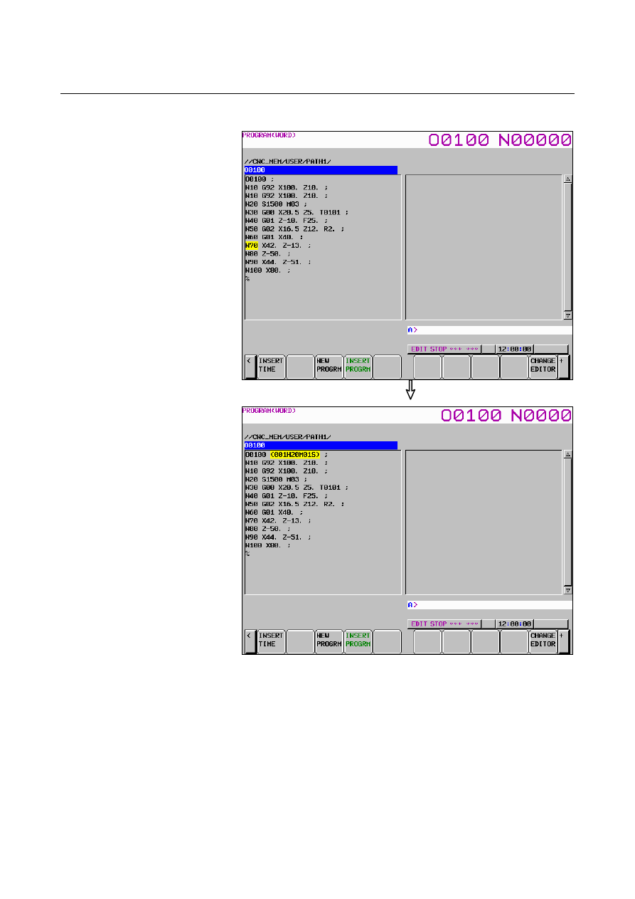
  Press soft key [INSERT TIME]. 


Fig. 12.2.8 (c) Program screen (10.4-inch) 


B-63944EN/03

 OPERATION 

12.SETTING AND DISPLAYING DATA


- 1493 - 

4  If a comment is written in the block containing the program 

number of a program of which machining time is to be inserted, 
the machining time is inserted after the comment. 


  Press soft key [INSERT TIME]. 


Fig. 12.2.8 (d) Program screen (10.4-inch) 


12.SETTING AND DISPLAYING DATA

 OPERATION 

B-63944EN/03


- 1494 - 

Display on the program folder screen 

 
The machining time of a program inserted in the program as a 
comment is displayed after the existing comment of the program on 
the program folder screen. 


Fig. 12.2.8 (e) Program folder screen (10.4-inch) 


B-63944EN/03

 OPERATION 

12.SETTING AND DISPLAYING DATA


- 1495 - 

Explanation 
 - Machining time 

The machining time is counted from the initial start after a reset in the 
memory operation mode to the next reset.    If a reset is not performed 
during operation, the machining time is counted from the start to M02 
or M30. The time during which operation is held is not counted, but 
the time used to wait for the completion of the M, S, T, and/or B 
functions is counted, however. 
 

  - Stamping the machining time 

You can insert (stamp) the displayed machining time in a program 
stored in memory as a comment. The machining time is inserted as a 
comment after the program number. 
 

 - Program folder 

You can display the machining time inserted after a program number 
on the program folder screen. This operation lets you know the 
machining time of each program to use the time as useful reference 
data when planning processes on site. 
 

Limitation 
 - Alarm 

The execution of a program may be held by an alarm during the 
machining time count operation. In this case, the machining time is 
counted until the alarm is released by a reset. 
 

 - M02 

It may be specified that M02 does not reset the CNC, but returns 
completion signal FIN to the CNC to restart the program from the 
beginning successively (bit 5 (M02) of parameter No. 3404 is set to 0). 
In this case, when M02 returns completion signal FIN, the machining 
time count operation stops. 
 

  - Stamping the machining time 

When an attempt is made to stamp the machining time of a program in 
the program, the machining time of the program may not be displayed 
on the machining time display screen. In this case, the machining time 
cannot be inserted in the program even if soft key [INSERT TIME] is 
pressed. 
 

  - Correcting the machining time 

If an incorrect machining time is calculated (such as when a reset is 
made during the execution of a program), reexecute the program to 
calculate the correct machining time. The same program number may 
be displayed in two or more lines on the machining time display 
screen. In this case, the latest calculated machining time is inserted in 
the program. 
 

12.SETTING AND DISPLAYING DATA

 OPERATION 

B-63944EN/03


- 1496 - 

  - States of the stamped machining time 

In the following states, the stamped machining time is displayed on 
the program folder screen as shown below. 
 
1  When the comment of a program is longer than 16 characters 

The 17th and subsequent characters of the comment are discarded 
and the machining time display field is left blank. 


Fig. 12.2.8 (f) 1. When the comment of a program is longer than 16 

characters (10.4-inch) 


B-63944EN/03

 OPERATION 

12.SETTING AND DISPLAYING DATA


- 1497 - 

When two or more machining times are stamped 
The first machining time is displayed. 


Fig. 12.2.8 (g)    When two or more machining times are stamped 

(10.4-inch) 


12.SETTING AND DISPLAYING DATA

 OPERATION 

B-63944EN/03


- 1498 - 

3  When the format of an inserted machining time is not 

“hhhHmmMssS” (H following a 3-digit number, M following a 
2-digit number, and S following a 2-digit number, in this order) 
The machining time display field is left blank. 


Fig. 12.2.8 (h) When the format of an inserted machining time is not 

“hhhHmmMssS” (H following a 3-digit number, M following a 2-digit 

number, and S following a 2-digit number, in this order) (10.4-inch) 


B-63944EN/03

 OPERATION 

12.SETTING AND DISPLAYING DATA


- 1499 - 

12.2.9 

Screen for Assistance in Entering Tilted Working Plane 

Command 

 
The screens for assistance in entering tilted working plane commands 
(hereinafter referred to as guidance screens) include a command type 
selection screen and a tilted working plane data setting screen. The 
command type selection screen is used to select a tilted working plane 
command. The tilted working plane data setting screen is used to set 
specified tilted working plane data required for the selected command. 
By making settings and performing operations on these guidance 
screens, a tilted working plane command block can be created. 
The created block is reflected as a new insertion to a program being 
edited or as a modification to an existing block. 
This function can be enabled by setting bit 1 (GGD) of parameter No. 
11304 to 1. 
 

Creation of a new block 

The following describes the procedure for creating a tilted working 
plane command block on guidance screens and for inserting the block 
to a program being edited on a program editing screen. 
 

On a program editing screen, display a program to which you 
want to insert a tilted working plane command block. 


The foreground editing screen, background editing screen, or 
MDI editing screen should be displayed. 


Displaying the foreground editing screen 
<1>  Select the EDIT mode. 
<2>  Press function key 

<3>  Press soft key [PROGRAM].   


Displaying the background editing screen 
<1>  Press function key 

<2>  Press soft key [FOLDER].   
<3> Press any of the cursor keys to move the cursor to a 

program to be edited in the background. 

<4> Press 

 key. 


Displaying the MDI editing screen 
<1>  Select the MDI mode. 
<2>  Press function key 

<3>  Press soft key [PROGRAM].   


The program editing screen is displayed. 


Content      ..     190      191      192      193     ..