FANUC Series 30i/300i/300is-MODEL A. Machining Center System. User's manual - page 195
 

  Index      Manuals     FANUC Series 30i/300i/300is-MODEL A. Machining Center System. User's manual (B-63944EN/03)


Search            copyright infringement  


Content      ..     193      194      195      196     ..


FANUC Series 30i/300i/300is-MODEL A. Machining Center System. User's manual - page 195


12.SETTING AND DISPLAYING DATA

 OPERATION 

B-63944EN/03


- 1516 - 


Shift of the Origin 


Specify, in a feature coordinate system, an amount of shift from 
the feature coordinate system origin specified for the 1st point 
(point P1). 


Rotation Angle about the Z-axis in F-Coordinate 


Specify an angle of rotation around the Z-axis of a feature 
coordinate system. The direction of rotation angle R is positive 
when a rotation is made clockwise as viewed in the Z-axis 
direction of the feature coordinate system. 


1st point (Origin of Feature Coordinate) 


Specify the origin (X, Y, and Z of point P1) of a feature 
coordinate system as coordinates in a workpiece coordinate 
system (for the absolute type) or the current feature coordinate 
system (for the incremental type). 


 2nd 

point 


Specify the coordinates (X, Y, and Z of point P2) of the 2nd 
point as coordinates in a workpiece coordinate system (for the 
absolute type) or the current feature coordinate system (for the 
incremental type). The 1st point and 2nd point determine the 
X-axis of the feature coordinate system. 


 3rd 

point 


Specify the coordinates (X, Y, and Z of point P3) of the 3rd point 
as coordinates in a workpiece coordinate system (for the absolute 
type) or the current feature coordinate system (for the 
incremental type). Among the directions normal to the X-axis, a 
direction with a smaller angle relative to the P1 

 P3 vector is 

the Y-axis of the feature coordinate system. 


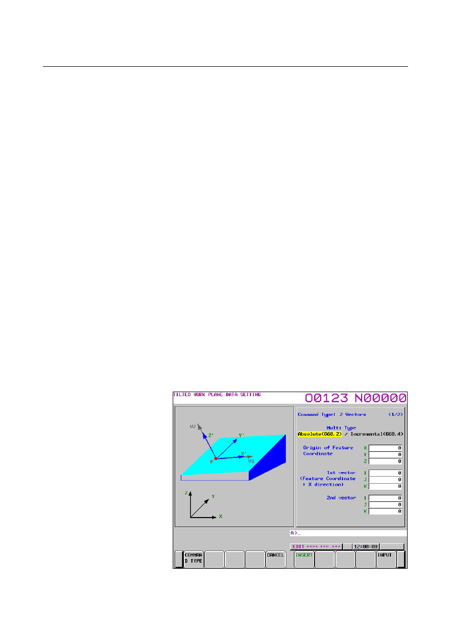
G68.2 / G68.4(2 vectors specification) 


Fig. 12.2.9.3 (d) Tilted working plane data setting screen-2 vectors 

specification(10.4-inch)  

B-63944EN/03

 OPERATION 

12.SETTING AND DISPLAYING DATA


- 1517 - 


 Multi 

Type 

Absolute: 
 

It is assumed that values of specified data are in a workpiece 
coordinate system, regardless of whether tilted working 
plane command mode is set. 

Incremental: 
 

It is assumed that values of specified data are in a feature 
coordinate system if tilted working plane command mode is 
already set. 


Origin of Feature Coordinate 


Specify the origin (X, Y, and Z of point P) of a feature 
coordinate system as coordinates in a workpiece coordinate 
system (for the absolute type) or the current feature coordinate 
system (for the incremental type). 


V1 (X’) vector 


Specify the X-axis direction vector of a feature coordinate 
system as values in a workpiece coordinate system (for the 
absolute type) or the current feature coordinate system (for the 
incremental type). 


V2 (Z’) vector 


Specify the Z-axis direction vector of a feature coordinate system 
as values in a workpiece coordinate system (for the absolute 
type) or the current feature coordinate system (for the 
incremental type). 


G68.2 / G68.4(Projection angle) 


Fig. 12.2.9.3 (e) Tilted working plane data setting screen-Projection 

angle(10.4-inch) 


12.SETTING AND DISPLAYING DATA

 OPERATION 

B-63944EN/03


- 1518 - 

 Multi 

Type 

Absolute: 
 

It is assumed that values of specified data are in a workpiece 
coordinate system, regardless of whether tilted working 
plane command mode is set. 

Incremental: 
 

It is assumed that values of specified data are in a feature 
coordinate system if tilted working plane command mode is 
already set. 


Origin of Feature Coordinate 


Specify the origin (X, Y, and Z of point P) of a feature 
coordinate system as coordinates in a workpiece coordinate 
system (for the absolute type) or the current feature coordinate 
system (for the incremental type). 


 Projection 

angle 

I  : Specify a projection angle relative to the X-axis of a 

workpiece coordinate system (for the absolute type) or the 
current feature coordinate system (for the incremental type). 

J  : Specify a projection angle relative to the Y-axis of a 

workpiece coordinate system (for the absolute type) or the 
current feature coordinate system (for the incremental type). 

K :  Specify an angle of rotation around the Z-axis of a feature 

coordinate system. 


G68.3(Tool Axis Direction) 


Fig. 12.2.9.3 (f) Tilted working plane data setting screen-Tool Axis 

Direction(10.4-inch) 

(When "No" is selected in "Origin command of Feature Coordinate") 


B-63944EN/03

 OPERATION 

12.SETTING AND DISPLAYING DATA


- 1519 - 


Fig. 12.2.9.3 (g) Tilted working plane data setting screen-Tool Axis 

Direction(10.4-inch) 

(When "Yes" is selected in "Origin command of Feature Coordinate") 


Origin command of Feature Coordinate 


Select whether to specify a feature coordinate system origin. 
Yes 

:  A feature coordinate system origin is specified. 

No 

:  A feature coordinate system origin is not specified. 


Origin of Feature Coordinate 


Specify the origin (X, Y, and Z of point P) of a feature 
coordinate system as coordinates in a workpiece coordinate 
system. 


This setting cannot be made if "No" is selected in "Origin 
command of Feature Coordinate". 


Rotation Angle about the Z-axis in F-Coordinate 


Specify an angle of rotation around the Z-axis of a feature 
coordinate system. The direction of rotation angle R is positive 
when a rotation is made clockwise as viewed in the Z-axis 
direction of the feature coordinate system. 


12.2.9.4 

Limitation 

 
This function is supported on 10.4-inch and 15-inch display units. 
This function is not displayed on 7.2-inch and 8.4-inch display units. 
 

12.SETTING AND DISPLAYING DATA

 OPERATION 

B-63944EN/03


- 1520 - 

Screens of a 15-inch display unit 

 
This section describes the screens displayed by pressing function key 

. The screens include a program editing screen, program folder 

list display screen, and screens for displaying the command states of 
the program currently being executed. 
1. Program 

screen 

2.  Program folder screen 
3.  Next block display screen 
4.  Program check screen 
 
On the program screen, you edit the program that is currently selected, 
and display the block that is currently executed during program 
operation. In MDI mode, you also edit an MDI operation program, 
and display the block that is currently executed. 
 

B-63944EN/03

 OPERATION 

12.SETTING AND DISPLAYING DATA


- 1521 - 

12.2.10 

Program Contents Display (15-inch Display Unit) 

 
Displays the program currently being executed in MEMORY mode. 
 

Displaying the program being executed 

Procedure 

1


 Press function key 

  to display the program screen. 

2  Press vertical soft key [PROGRAM].   

The cursor is positioned at the block currently being executed. 


Fig. 12.2.10 (a) Screen for displaying the program being executed 

(15-inch) 


12.2.10.1 

Displaying the executed block 

 
For an explanation of how to display the executed block, see 
Subsection 12.2.1.1, "Displaying the executed block". 
 

12.SETTING AND DISPLAYING DATA

 OPERATION 

B-63944EN/03


- 1522 - 

12.2.11 

Editing a Program (15-inch Display Unit) 

 
A program can be edited in the EDIT mode. 
Two modes of editing are available. One mode is word editing, which 
performs word-by-word editing. The other is character editing, which 
performs character-by-character editing. 
For program creation and editing operation, see Chapter III-9, 
“CREATING PROGRAMS “ and Chapter III-10, “EDITING 
PROGRAMS”. 
 

Displaying the program editing screen 

Procedure 

Press function key 

  to display the program screen. 

Press vertical soft key [PROGRAM].   


 - Word editing 

Editing operations such as text insertion, modification, and deletion, 
and cursor movements are performed on a word-by-word basis. 


Fig. 12.2.11 (a) Program word editing screen (15-inch) 


B-63944EN/03

 OPERATION 

12.SETTING AND DISPLAYING DATA


- 1523 - 

 - Character editing 

Program editing operations and cursor movements are performed on a 
character-by-character basis as with a general text editor. 
Text is input directly to the cursor position instead of using the key 
input buffer. 


Fig. 12.2.11 (b) Program character editing screen (15-inch) 


Switching between program editing modes 

You can switch between word editing and character editing with 
horizontal soft keys. 
 

Procedure 

1  Press function key 

  to display the program screen. 

2  Press vertical soft key [PROGRAM].   
3  Press continuous menu key 

 to display horizontal soft key 

[CHANGE EDITOR]. 

4  Pressing horizontal soft key [CHANGE EDITOR] switches the 

editing mode between word editing and character editing. 


Content      ..     193      194      195      196     ..