FANUC Series 30i/300i/300is-MODEL A. Machining Center System. User's manual - page 132
 

  Index      Manuals     FANUC Series 30i/300i/300is-MODEL A. Machining Center System. User's manual (B-63944EN/03)


Search            copyright infringement  


Content      ..     130      131      132      133     ..


FANUC Series 30i/300i/300is-MODEL A. Machining Center System. User's manual - page 132


2.OPERATIONAL DEVICES

 OPERATION 

B-63944EN/03


- 1012 - 

2.3.2 

Function Keys 

 
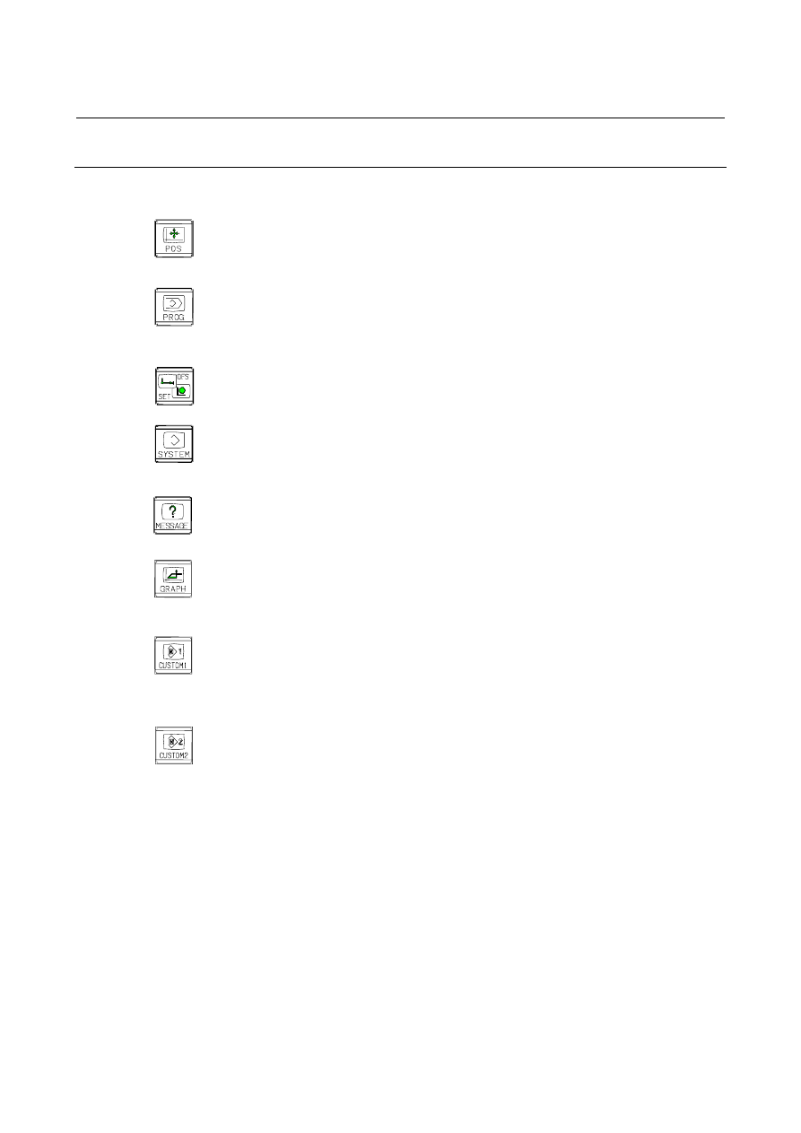
Function keys are provided to select the type of screen to be displayed. 
The following function keys are provided on the MDI panel: 
 
Press this key to display the position screen. 


Press this key to display the program screen. 


Press this key to display the offset/setting screen. 


Press this key to display the system screen. 


Press this key to display the message screen. 


Press this key to display the graphics screen. 


Press this key to display the custom screen 1 (conversational macro 
screen or C language executor screen). 


Press this key to display the custom screen 2 (conversational macro 
screen or C language executor screen). 


B-63944EN/03

 OPERATION 

2.OPERATIONAL DEVICES


- 1013 - 

2.3.3 

Soft Keys 

 
By pressing a soft key after a function key, the corresponding screen 
of the function can be displayed. 
 
The chapter selection soft keys of each function are described below. 
The horizontal four keys on the right-hand side are assigned to chapter 
selection soft keys.  When multiple pages are used for chapter 
selection soft keys, [+] is displayed on the continuous menu key 
(rightmost soft key).  Press the continuous menu key to switch 
between chapter selection soft keys. 
 

NOTE 

1  Press function keys to switch between screens that 

are used frequently. 

2  Some soft keys are not displayed depending on the 

option configuration. 

 
If position indications are provided on the left half of the screen when 
a key other than the function key 


is pressed, the left half of the 

soft keys is displayed as follows at all times:


2.OPERATIONAL DEVICES

 OPERATION 

B-63944EN/03


- 1014 - 

Position display screen 

The chapter selection soft keys that belong to the function key 


and the function of each screen are described below. 
 

ABS 

REL 

ALL 

HNDL 

(OPRT)

Page 1 

+

(1)

(2)

(3)

(4) (5) 

MONI 

3-D 

MANUAL


(OPRT)

Page 2 

+

(6)

(7)

(8)

(9) (10) 


Table 2.3.3 (a)    Position display screen 

No. Chapter 

menu

Description 

(1) 

ABS 

Selects the absolute coordinate display screen. 

(2) 

REL 

Selects the relative coordinate display screen. 

(3) 

ALL 

Selects the overall coordinate display screen. 

(4) HNDL 


Selects the operation screen for manual handle 
operation. 

(6) 

MONI 

Selects the screen for displaying the servo axis load 
meter, serial spindle load meter, and speedometer.

(7) 3-D 

MANUAL 

Displays a handle pulse interrupt amount in 
three-dimensional manual feed. 


B-63944EN/03

 OPERATION 

2.OPERATIONAL DEVICES


- 1015 - 

Program screen 

The chapter selection soft keys that belong to the function key 


and the function of each screen are described below. 
 

PROGRA

M

FOLDER

NEXT


CHECK


(OPRT)


Page 1 

+

(1)

(2)

(3)

(4) (5) 

TIME 

JOG 

RSTR


(OPRT) 

Page 2 

+

(6)

(7)

(8)

(9) (10) 


Table 2.3.3 (b)    Program 

No. Chapter 

menu

Description 

(1) 

PROGRAM

Selects the screen for displaying a list of part 
programs currently registered. 

(2) 

FOLDER 

Selects the screen for displaying a list of part 
programs currently registered. 

(3) 

NEXT 

Selects the screen for displaying the command 
values of the block currently executed and the next 
block to be executed among the command values.

(4) 

CHECK 

Selects the screen for displaying programs, position 
data, modal information, and so forth 
simultaneously. 

(6) 

TIME 

Selects the screen for displaying executed program 
operation time. 

(7) 

JOG 

Selects the screen for executing, in the JOG mode, 
data specified in the program format from the MDI.

(8) 

RSTR 

Selects the operation screen for restarting an 
interrupted program operation. 


2.OPERATIONAL DEVICES

 OPERATION 

B-63944EN/03


- 1016 - 

Offset/setting screen 

The chapter selection soft keys that belong to the function key 


and the function of each screen are described below. 
 

OFFSET

SETTING

WORK 


(OPRT)

Page 1 

+

(1)

(2)

(3)

(4) (5) 

MACRO


OPR


TOOL 

MANAGER 

(OPRT)

Page 2 

+

(6)

(7)

(8)

(9) (10) 

OFST.2

W.SHFT

GEOM.2


(OPRT)

Page 3 

+

(11)

(12)

(13)

(14) (15) 


PR-LV 

EXTEND 

OFFSET


(OPRT)

Page 4 

+

CHUCK 

TAIL


LANG.


PROTECT

GUARD 

(OPRT)

Page 5 

+

(16)

(17)

(18)

(19) (20) 

(21)

(22)

(23)

(24) (25) 


TOOL 

LIFE 

(OPRT)

Page 6 

(26)

(27)

(28)

(29) (30) 

WORK  

SET ER


(OPRT)

Page 7 

(31)

(32)

(33)

(34) (35) 


B-63944EN/03

 OPERATION 

2.OPERATIONAL DEVICES


- 1017 - 


Table 2.3.3 (c)    Offset 

No. Chapter 

menu

Description 

(1) 

OFFSET 

Selects the screen for setting tool offset values. 

(2) 

SETTING 

Selects the screen for setting the setting 
parameters. 

(3) 

WORK 

Selects the screen for setting a workpiece 
coordinate system offset. 

(6) 

MACRO 

Selects the screen for setting macro variables. 

(8) 

OPR 

Selects the screen for operating some operation 
switches on the machine operator's panel as soft 
switches. 

(9) TOOL 

MANAGER

Selects the screen for setting data related to tool 
management. 

(11) 

OFST.2 

Selects the screen for setting a Y-axis offset. 

(12) 

W.SHFT 

Selects the screen for setting a workpiece 
coordinate system shift value. 

(13) 

GEOM.2 

Selects the screen for setting a second geometry 
offset. 

(17) 

PR-LV 

Selects the screen for setting a precision level. 

(18) EXTEND 

OFFSET 

Selects the screen for setting the offsets of the 
fourth and fifth axes. 

(21) 

CHUCK TAIL Selects the chuck tail stock barrier screen. 

(22) 

LANG. 

Selects the screen for setting a display language. 

(23) 

PROTECT  Selects the screen for setting data protection. 

(24) 

GUARD 

Selects the screen for setting wrong operation 
prevention. 

(29) 

TOOL LIFE

Selects the screen for operations and setting related 
to tool life management. 

(31) WRK 

ERR 

COMP 

Selects the screen for setting errors related to 
workpiece mounting position. 


2.OPERATIONAL DEVICES

 OPERATION 

B-63944EN/03


- 1018 - 

System screen 

The chapter selection soft keys that belong to the function key 


and the function of each screen are described below. 
 

PARAM


DGNOS

SERVO 

GUIDEM

SYSTEM 

(OPRT)


Page 1 

+

(1)

(2)

(3)

(4) (5) 

MEMORY

PITCH


SERVO 
PARAM

SP.SET 

(OPRT) 

Page 2 

+

(6)

(7)

(8)

(9) (10) 

PMC 

MAINTE

PMC 

LADDER

PMC 

CONFIG


Page 3 

+

(11)

(12)

(13)

(14) (15) 

MCNG 

TUNING


ALL IO


OPEHIS


(OPRT)


Page 4 

+

COLOR

MAINTE

M-INFO

W. DGNS 

(OPRT) 

Page 5 

+

(16)

(17)

(18)

(19) (20) 

(21)

(22)

(23)

(24) (25) 


FSSB 

PRMTUN

P.MATE 

MGR. 

(OPRT) 

Page 6 

+

(26)

(27)

(28)

(29) (30) 

EMBED 

PORT 

PCMCIA

LAN 

ETHNET 

BOARD

PROFI 

MASTER


(OPRT)


Page 7 

+

(31)

(32)

(33)

(34) (35) 


B-63944EN/03

 OPERATION 

2.OPERATIONAL DEVICES


- 1019 - 


M CODE


3D ERR 

COMP 

(OPRT) 

Page 8 

(36)

(37)

(38)

(39) (40) 


(OPRT) 

Page 9 

(41)

(42)

(43)

(44) (45) 

DUAL  

CHECK

R.TIME

MACRO


(OPRT) 

Page 10 

(46)

(47)

(48)

(49) (50) 


Table 2.3.3 (d)    System 

No. Chapter 

menu

Description 

(1) 

PARAM 

Selects the screen for setting parameters. 

(2) 

DGNOS 

Selects the screen for displaying CNC state.


(3) 

SERVO GUIDEM Selects the screen for displaying the servo guide mate.

(4) 

SYSTEM 

Selects the screen for displaying the current system 
status. 

(6) 

MEMORY 

Selects the screen for displaying the contents of 
memory. 

(7) 

PITCH 

Selects the screen for setting pith error compensation.

(8) 

SERVO PARAM Selects the screen for setting the servo-related 

parameters. 

(9) 

SP.SET 

Selects the screen for spindle-related setting. 

(11) 

PMC MAINTE  Selects the screen related to PMC maintenance such 

as PMC signal state monitoring and tracing, and PMC 
parameter display/editing. 

(12) 

PMC LADDER  Selects the screen related to ladder display/editing. 

(13) 

PMC CONFIG  Displays the screen for displaying/editing data other 

than ladders that makes up a sequence program and 
for setting the PMC function. 

(16) 

MCNG TUNING Displays the screen for setting the parameter set for 

emphasis on speed (LV1) or emphasis on precision 
(LV10). 

(18) 

ALL IO 

Selects the screen for data input to and output from the 
memory card. 

(19) 

OPEHIS 

Selects the screen for displaying the history of 
operations performed by the operator and issued 
alarms. 

(21) 

COLOR 

Selects the screen for setting colors to be used on the 
screen. 

(22) 

MAINTE 

Selects the screen for setting maintenance items to be 
managed periodically. 

(23) 

M-INFO 

Selects the screen for displaying information about 
maintenance performed.   


Content      ..     130      131      132      133     ..