FANUC Series 30i/300i/300is-MODEL A. Machining Center System. User's manual - page 133
 

  Index      Manuals     FANUC Series 30i/300i/300is-MODEL A. Machining Center System. User's manual (B-63944EN/03)


Search            copyright infringement  


Content      ..     131      132      133      134     ..


FANUC Series 30i/300i/300is-MODEL A. Machining Center System. User's manual - page 133


2.OPERATIONAL DEVICES

 OPERATION 

B-63944EN/03


- 1020 - 

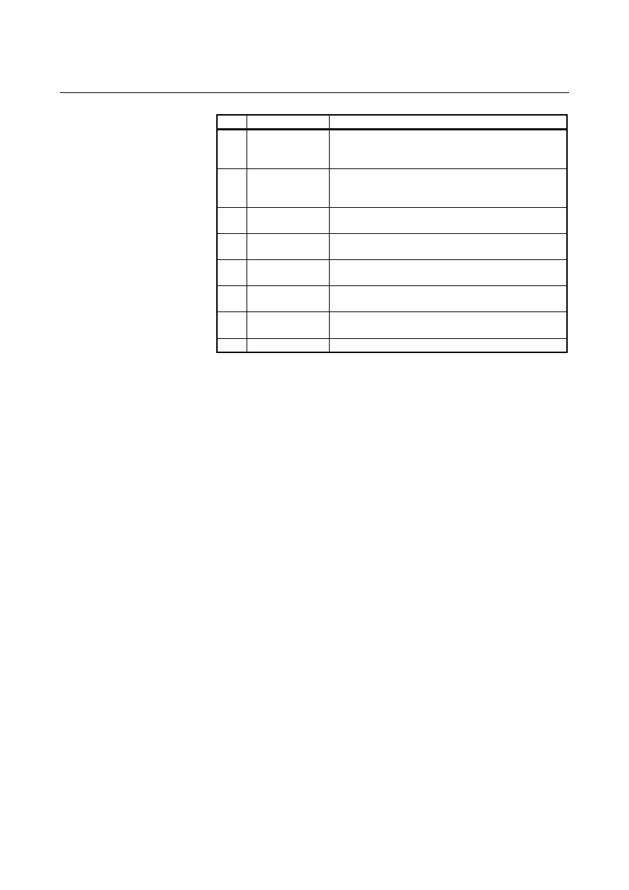
No. Chapter 

menu

Description 

(24) 

W.DGNS 

Selects the screen for displaying data such as servo 
positional deviation values, torque values, machine 
signals, and so forth as graphs. 

(27) 

FSSB 

Selects the screen for making settings related to the 
high-speed serial servo bus (FSSB: Fanuc Serial Servo 
Bus). 

(28) 

PRMTUN 

Selects the screen for setting parameters necessary for 
start-up and tuning. 

(31) 

EMBED PORT

Selects the screen for making settings related to the 
embedded Ethernet (embedded port).   

(32) 

PCMCIA LAN 

Selects the screen for making settings related to the 
embedded Ethernet (PCMCIA Ethernet card). 

(33)  ETHNET BOARD Selects the screen for making settings related to the 

fast Ethernet/fast data server. 

(34)  PROFI MASTER Selects the screen for making settings related to the 

profibus master function. 

(37) 

M CODE 

Selects the screen for setting an M code group. 

B-63944EN/03

 OPERATION 

2.OPERATIONAL DEVICES


- 1021 - 

Message screen 

The chapter selection soft keys that belong to the function key 


and the function of each screen are described below. 
 

ALARM

MSG


HISTRY

MSGHIS 

(OPRT)


Page 1 

+

(1)

(2)

(3)

(4) (5) 

EMBED  

LOG


PCMCIA

LOG 

BOARD

LOG 


(OPRT) 

Page 2 

+

(6) (7) (8) (9) (10) 


Table 2.3.3 (e)    Message 

No. Chapter 

menu

Description 

(1) 

ALARM 

Selects the alarm message screen. 

(2) 

MSG 

Selects the operator message screen. 

(3) 

HISTRY 

Selects the screen for displaying the details of 
alarms issued so far. 

(4) 

MSGHIS 

Selects the external operator message screen. 

(6) 

EMBED LOG Selects the screen for displaying error messages 

related to the embedded Ethernet (embedded port).

(7) 

PCMCIA LOG Selects the screen for displaying error messages 

related to the embedded Ethernet (PCMCIA 
Ethernet card). 

(8) 

BOARD LOG Selects the screen for displaying error messages 

related to the fast Ethernet/fast data server. 


2.OPERATIONAL DEVICES

 OPERATION 

B-63944EN/03


- 1022 - 

Graphic screen 

The chapter selection soft keys that belong to the function key 


and the function of each screen are described below. 
 
When the graphic display function is enabled: 
 

PARAM


GRAPH


(OPRT)


Page 1 

+

(1)

(2)

(3)

(4) (5) 


Table 2.3.3 (f)    Graphic 

No. Chapter 

menu

Description 

(1) 

PARAM 

Selects the screen for setting graphic parameters. 

(2) 

GRAPH 

Selects the screen for graphically displaying the tool 
path. 

 
When the dynamic graphic display function is enabled: 
 

DRAW 

PARAM

PATH 

EXEC


ANIME 

EXEC


TOOL 

POS 

(OPRT)


Page 1 


(1)

(2)

(3)

(4) (5) 


Table 2.3.3 (g)    Graphic 

No. Chapter 

menu

Description 

(1) DRAW 

PARAM 

Selects the screen for setting drawing parameters.

(2) 

PATH EXEC Selects the screen for drawing tool paths. 

(3) ANIME 


EXEC 

Selects the screen for drawing animation. 

(4) 

TOOL POS

Selects the screen for displaying tool positions. 


B-63944EN/03

 OPERATION 

2.OPERATIONAL DEVICES


- 1023 - 

2.3.4 

Key Input and Input Buffer 

 
When an address and a numeric key are pressed, the character 
corresponding to that key is input once into the key input buffer. The 
contents of the key input buffer is displayed at the bottom of the 
screen. 
In order to indicate that it is key input data, a ">" symbol is displayed 
immediately in front of it.    A "_" is displayed at the end of the key 
input data indicating the input position of the next character. 


Fig. 2.3.4 (a)    Key input buffer display 


  - Switching between upper and lower key characters 

To input the lower character of the keys that have two characters 
inscribed on them, first press the 

 key and then the key in 

question. 
When the 

 key is pressed, "_" indicating the next character 

input position changes to "^". Now lowercase characters can be 
entered (shift state). 
When a character is input in shift status the shift status is canceled.  
Furthermore, if the 

  key is pressed in shift status, the shift status 

is canceled. 
It is possible to input up to 128 characters at a time in the key input 
buffer. 
Press the 

  key to cancel a character or symbol input in the key 

input buffer. 
 
(Example) 
 

When the key input buffer displays 

 >N001X100Z_ 
 

and the cancel 

  key is pressed, Z is canceled and 

 >N001X100_ 
 is 

displayed. 


Key input buffer display 

2.OPERATIONAL DEVICES

 OPERATION 

B-63944EN/03


- 1024 - 

  - Switching between uppercase and lowercase alphabetic characters 

When entering alphabetic characters, the user can switch between 
uppercase and lowercase. 
By pressing the uppercase/lowercase switch key 

, the display of 

the key input buffer changes to enable uppercase or lowercase 
alphabetic characters to be entered as described below. 
Example) 

  A> A B C _ 
 

State enabling uppercase input


 a>  a b c _ 
 

State enabling lowercase input


2.3.5 

Warning Messages 

 
After a character or number has been input from the MDI panel, a data 
check is executed when 

  key or a soft key is pressed.    In the 

case of incorrect input data or the wrong operation a flashing warning 
message will be displayed on the status display line. 


Fig. 2.3.5 (a)    Warning message display 


Table 2.3.5 (a)    Warning Messages 

Warning message 

Content 

FORMAT ERROR 

The format is incorrect. 

WRITE PROTECT 

Key input is invalid because of data protect 
key or the parameter is not write enabled. 

DATA IS OUT OF RANGE 

The input value exceeds the permitted range.

TOO MANY DIGITS 

The input value exceeds the permitted 
number of digits. 

WRONG MODE 

Parameter input is not possible in any mode 
other than MDI mode. 

EDIT REJECTED 

It is not possible to edit in the current CNC 
status. 


Key input buffer display 

Soft key display 

State display 

Warning message display 


B-63944EN/03

 OPERATION 

2.OPERATIONAL DEVICES


- 1025 - 

2.4 

EXTERNAL I/O DEVICES 

 
External I/O devices such as a memory card are available. 
By using an external I/O device such as a memory card, the following 
data can be input or output: 
1.  

Programs 

2. Offset 

data 

3. Parameters 
4.  Custom macro common variables 
For how to input or output data and input data from or output it to a 
memory card, see III-8. 
 

 - Parameter setting 

Before an external input/output device can be used, parameters must 
be set as follows. 

Main board 

Channel 1 

Channel 2 

JA56A

JA36A 

RS-232-C 

RS-232-C

Reader/
puncher 

Reader/
puncher

I/O CHANNEL=0

or

I/O CHANNEL=1

I/O CHANNEL=2 

CNC


This CNC has a total of two channels of reader/puncher interfaces.    It 
also has a memory card interface. The input/output device to be used 
is specified by setting the channel (interface) connected to that device 
in setting parameter I/O CHANNEL. 
The specified data, such as a baud rate and the number of stop bits, of 
an input/output device connected to a specific channel must be set in 
parameters for that channel in advance. (These settings are not 
required for the memory card interface.) 
For channel 1, two combinations of parameters to specify the 
input/output device data are provided. 
The following shows the interrelation between the reader/puncher 
interface parameters for the channels. 
 

2.OPERATIONAL DEVICES

 OPERATION 

B-63944EN/03


- 1026 - 

    I/O CHANNEL
or foreground input

Set channels to be used
for data input/output.

I/O CHANNEL (0 to 5)

=0 : Channel 1
=1 : Channel 1
=2 : Channel 2
=3 : Channel 3
:
:
:

Input/output to and from the memory
card interface, etc. is also possible.

When IO4 is set

Foreground output

Background input

Background input

The channel setting is the same as
No.0020.

Input/output channel number (parameter No.0020)

    0101    Stop bit and other data

I/O CHANNEL=0

    0102    Number specified for the input/output device

    0103    Baud rate

    0111    Stop bit and other data

I/O CHANNEL=1

    0112    Number specified for the input/output device

        0113        Baud rate

    0121    Stop bit and other data

I/O CHANNEL=2

    0122    Number specified for the input/output device

    0123    Baud rate

:

:

:

I/O CHANNEL=5

(Channel 1)

(Channel 1)

(Channel 2)

0020

0021

0022

0023


B-63944EN/03

 OPERATION 

2.OPERATIONAL DEVICES


- 1027 - 

2.5 

POWER ON/OFF 


2.5.1 

Turning on the Power 


Procedure of turning on the power 


Procedure 

Check that the appearance of the CNC machine tool is normal.   


(For example, check that front door and rear door are closed.) 

2  Turn on the power according to the  manual issued by the 

machine tool builder. 

After the power is turned on, check that the position screen is 
displayed. An alarm screen is displayed if an alarm occurs upon 
power-on.  


Fig. 2.5.1 (a)    Position screen (for machining center system) 


Check that the fan motor is rotating. 


 WARNING 


Until the positional or alarm screen is displayed at 
the power on, do not touch them.    Some keys are 
used for the maintenance or special operation 
purpose.  When they are pressed, unexpected 
operation may be caused. 


Content      ..     131      132      133      134     ..