FANUC Series 30i/300i/300is-MODEL A. Machining Center System. User's manual - page 9
 

  Index      Manuals     FANUC Series 30i/300i/300is-MODEL A. Machining Center System. User's manual (B-63944EN/03)


Search            copyright infringement  


Content      ..     7      8      9      10     ..


FANUC Series 30i/300i/300is-MODEL A. Machining Center System. User's manual - page 9


1.GENERAL


PROGRAMMING


B-63944EN/03


- 28 - 

1.5 

SELECTION OF TOOL USED FOR VARIOUS MACHINING - 
TOOL FUNCTION 


Overview 

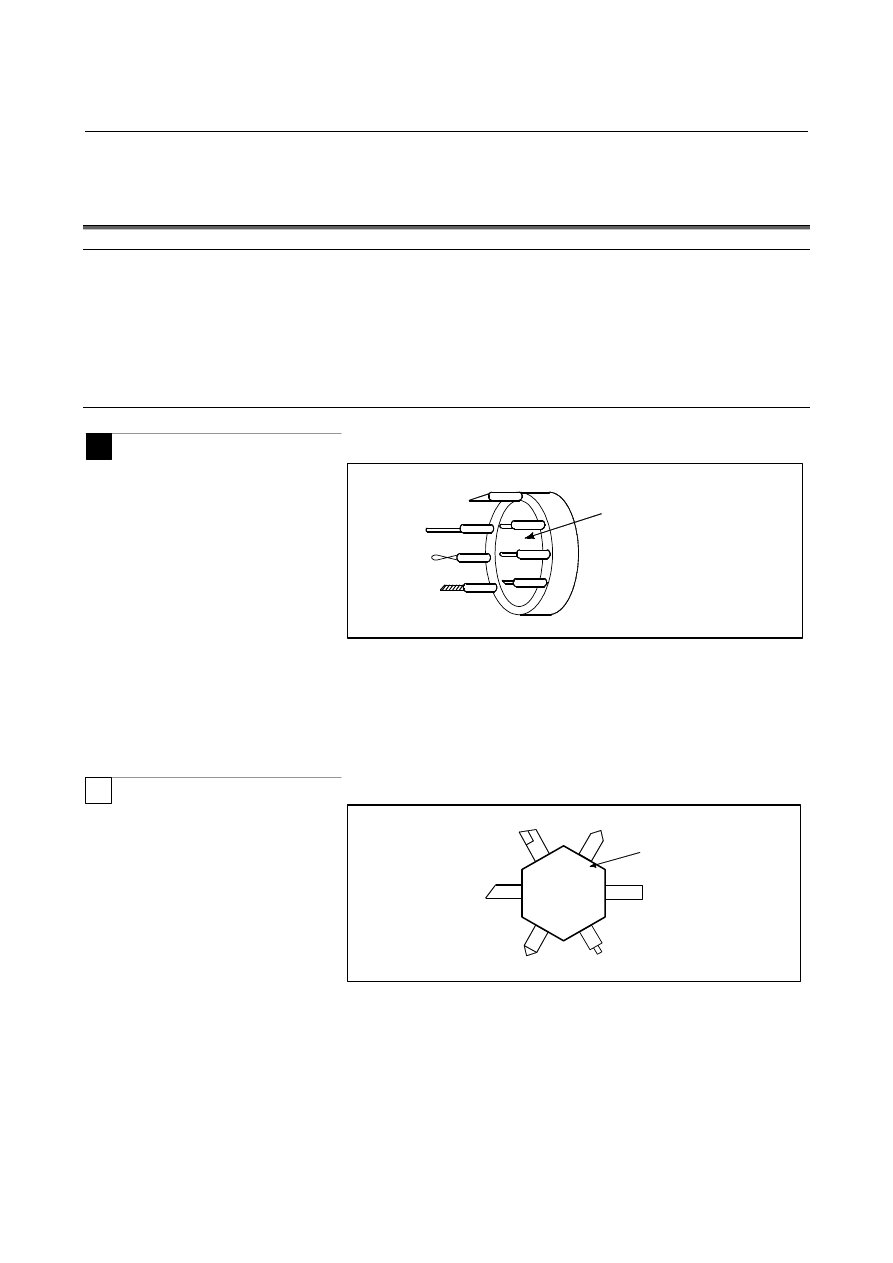
For each of various types of machining (such as drilling, tapping, 
boring, and milling for milling machining, or rough machining, 
semifinish machining, finish machining, threading, and grooving for 
lathe cutting), a necessary tool is to be selected. When a number is 
assigned to each tool and the number is specified in the program, the 
corresponding tool is selected. 
 

Examples 

M


01 

02

Tool number 

ATC magazine 


Fig. 1.5 (a)  Tool used for various machining 

 
<When No.01 is assigned to a drilling tool> 
When the tool is stored at location 01 in the ATC magazine, the tool 
can be selected by specifying T01. This is called the tool function (See 
II-10). 
 

T


Tool number 

Tool post 

01

06

02

05

04

03


Fig. 1.5 (b)  Tool used for various machining 

 
<When No.01 is assigned to a roughing tool> 
When the tool is stored at location 01 of the tool post, the tool can be 
selected by specifying T0101. This is called the tool function (See II-
10). 
 

B-63944EN/03

 PROGRAMMING 

1.GENERAL


- 29 - 

1.6 

COMMAND FOR MACHINE OPERATIONS - AUXILIARY 
FUNCTION 

 
When a workpiece is actually machined with a tool, the spindle is 
rotated, coolant is supplied, and the chuck is opened/closed. So, 
control needs to be exercised on the spindle motor of the machine, 
coolant valve on/off operation, and chuck open/close operation. 
 

 For 

milling 

machining 


Workpiece

Tool

Coolant on/off 

Spindle 
rotation 


For lathe cutting 


Workpiece

Chuck open/close 

Spindle rotation 

Coolant on/off 


Fig. 1.6 (a)  Auxiliary function 


The function of specifying the on-off operations of the components of 
the machine is called the auxiliary function. In general, the function is 
specified by an M code (See II-11). 
For example, when M03 is specified, the spindle is rotated clockwise 
at the specified spindle speed. 
 

1.GENERAL


PROGRAMMING


B-63944EN/03


- 30 - 

1.7 

PROGRAM CONFIGURATION 

 
A group of commands given to the CNC for operating the machine is 
called the program. By specifying the commands, the tool is moved 
along a straight line or an arc, or the spindle motor is turned on and off. 
In the program, specify the commands in the sequence of actual tool 
movements. 


Block 

Block 

Block 

Block

:
:
:
:

Block 

Program 

Tool movement 
sequence 


Fig. 1.7 (a)  Program configuration 

 
A group of commands at each step of the sequence is called the block. 
The program consists of a group of blocks for a series of machining. 
The number for discriminating each block is called the sequence 
number, and the number for discriminating each program is called the 
program number (See II-13). 

B-63944EN/03

 PROGRAMMING 

1.GENERAL


- 31 - 

Explanation 

The block and the program have the following configurations. 
 

 -  Block 

End of block 

Nxxxxx          Gxx            Xxxx.x Yxxx.x         Mxx     Sxx     Txx     ;

1 block 

Sequence 
number 

Preparatory 
function 

Auxiliary 
function 

Spindle 
function 

Tool 
function

Dimension word 


Fig. 1.7 (b)  Block configuration 

 
A block starts with a sequence number to identify the block and ends 
with an end-of-block code. 
This manual indicates the end-of-block code by; (LF in the ISO code 
and CR in the EIA code). 
The contents of the dimension word depend on the preparatory 
function. In this manual, the portion of the dimension word may be 
represent as IP_. 
 

 -  Program 


Oxxxxx ; 

Program number 

Block 

Block 

Block 

:

:

:

M30 ; 

End of program 

:

:

:


Fig. 1.7 (c)  Program configuration 

 
Normally, a program number is specified after the end-of-block (;) 
code at the beginning of the program, and a program end code (M02 
or M30) is specified at the end of the program. 
 

1.GENERAL


PROGRAMMING


B-63944EN/03


- 32 - 

 -  Main program and subprogram 

When machining of the same pattern appears at many portions of a 
program, a program for the pattern is created. This is called the 
subprogram. On the other hand, the original program is called the 
main program. When a subprogram execution command appears 
during execution of the main program, commands of the subprogram 
are executed. When execution of the subprogram is finished, the 
sequence returns to the main program. 


Main program 

M98P1001

:

:

M98P1002

:

:

:

:

:

:

:

:

Subprogram #1 

Subprogram #2 

O1001


M99


O1002


M99


M98P1001


Fig. 1.7 (d)  Subprogram execution 


B-63944EN/03

 PROGRAMMING 

1.GENERAL


- 33 - 

1.8 

TOOL MOVEMENT RANGE - STROKE 

 
Limit switches are installed at the ends of each axis on the machine to 
prevent tools from moving beyond the ends. The range in which tools 
can move is called the stroke. 


Stroke area 

Motor

Limit 
switch 

Machine zero point

 
Besides strokes defined with limit switches, the operator can define an 
area which the tool cannot enter using a program or data in memory. 
This function is called stroke check  (see III-6.3). 


Motor

Limit 
switch 

Specify these distances.

Machine zero point 

Tools cannot enter this area. The area is 
specified by data in memory or a program. 


2.CONTROLLED AXES


PROGRAMMING


B-63944EN/03


- 34 - 

CONTROLLED AXES 

 
Chapter 2, "CONTROLLED AXES", consists of the following 
sections: 
 
2.1  NUMBER OF CONTROLLED AXES.......................................35 
2.2 NAMES OF AXES .....................................................................36 
2.3 INCREMENT SYSTEM.............................................................37 
2.4 MAXIMUM STROKE................................................................38 
 

B-63944EN/03

 PROGRAMMING 

2.CONTROLLED AXES


- 35 - 

2.1 

NUMBER OF CONTROLLED AXES 


Explanation 

The number of controlled axes used with this NC system depends on 
the model and system control type as indicated below. 


NOTE 

1  The maximum number of controlled axes that can 

be used is limited depending on the option 
configuration.  Refer to the manual provided by the 
machine tool builder for details. 

2  The number of simultaneously controllable axes for 

manual operation (jog feed, manual reference 
position return, or manual rapid traverse) is 1 or 3 
(1 when bit 0 (JAX) of parameter No. 1002 is set to 
0 and 3 when it is set to 1). 


Series 30

i

-A 

Series 300

i

-A 

Series 300

i

s-A

Series 31

i

-A5 

Series 310

i

-A5

Series 310

i

s-A5

Series 31

i

-A 

Series 310

i

-A 

Series 310

i

s-A 

Series 32

i

-A 

Series 320

i

-A 

Series 320

i

s-A

Lathe system 

2 axes 

2 axes 

2 axes 

2 axes 

Number of basic 
controlled axes 

Machining 
center system 

3 axes 

3 axes 

3 axes 

3 axes 

Controlled axes expansion (total) 
 (including Cs axes and PMC axes) 

Max. 32 axes 

Max. 20 axes 

Max. 20 axes 

Max. 9 axes 

Basic simultaneously controlled axes 
(each path) 

2 axes 

2 axes 

2 axes 

2 axes 

Simultaneously controlled axes 
expansion  (total /  each path) 

Max. 24 axes 

Max. 12 axes 

Max. 12 axes 

Max. 5 axes 


Content      ..     7      8      9      10     ..