FANUC Series 30i/300i/300is-MODEL A. Machining Center System. User's manual - page 10
 

  Index      Manuals     FANUC Series 30i/300i/300is-MODEL A. Machining Center System. User's manual (B-63944EN/03)


Search            copyright infringement  


Content      ..     8      9      10      11     ..


FANUC Series 30i/300i/300is-MODEL A. Machining Center System. User's manual - page 10


2.CONTROLLED AXES


PROGRAMMING


B-63944EN/03


- 36 - 

2.2 

NAMES OF AXES 


Explanation 

The move axes of machine tools are assigned names. These names are 
referred to as addresses or axis names.  Axis names are determined 
according to the machine tool. The naming rules comply with 
standards such as the ISO standards. 
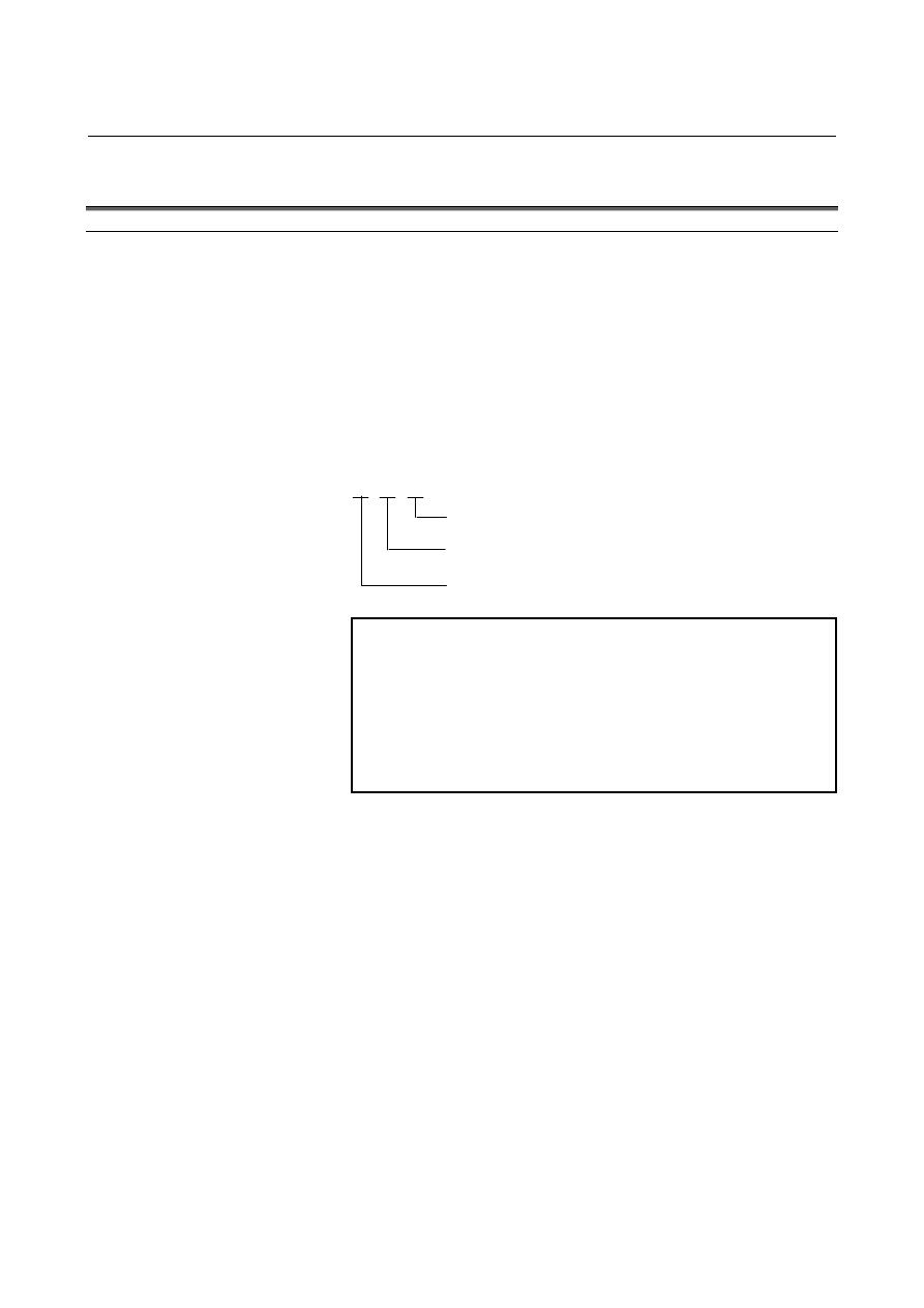
With complex machines, one character would become insufficient for 
representing axis names. So, up to three characters can be used for 
axis names. A move axis may be named "X", "X1", or "XA1".  The 
first character of the three characters is called the first axis name 
character, the second character is called the second axis name 
character, and third character is called the third axis name character. 
Example) 

X  A  1

3rd axis name character

2nd axis name character

1st axis name character


NOTE 

1  Axis names are predetermined according to the 

machine used. Refer to the manual supplied by the 
machine tool builder. 

2  Since many ordinary machines use one character 

to represent each address, one-character 
addresses are used in the description in this 
manual. 


B-63944EN/03

 PROGRAMMING 

2.CONTROLLED AXES


- 37 - 

2.3 

INCREMENT SYSTEM 


Explanation 

The increment system consists of the least input increment (for input) 
and least command increment (for output). The least input increment 
is the least increment for programming the travel distance. The least 
command increment is the least increment for moving the tool on the 
machine.  Both increments are represented in mm, inches, or deg. 
Five types of increment systems are available as indicated in Table 2.3 
(a). For each axis, an increment system can be set using a bit from bit 
0 to bit 3 (ISA, ISC, ISD, or ISE) of parameter No. 1013. 
IS-C, IS-D, and IS-E are optional functions. 
 

Table 2.3 (a)  Increment system 

Name of increment 

system 

Least input increment 

Least command 

increment 

0.01 mm  0.01 mm 
0.001 inch 

0.001 inch 

IS-A 

0.01 deg  0.01 deg 
0.001 mm 

0.001 mm 

0.0001 inch 

0.0001 inch 

IS-B 

0.001 deg 

0.001 deg 

0.0001 mm 

0.0001 mm 

0.00001 inch 

0.00001 inch 

IS-C 

0.0001 deg 

0.0001 deg 

0.00001 mm 

0.00001 mm 

0.000001 inch 

0.000001 inch 

IS-D 

0.00001 deg 

0.00001 deg 

0.000001 mm 

0.000001 mm 

0.0000001 inch 

0.0000001 inch 

IS-E 

0.000001 deg 

0.000001 deg 

 
The least command increment is either metric or inch depending on 
the machine tool. Set metric or inch to the parameter INM 
(No.0100#0). 
For selection between metric and inch for the least input increment, G 
code (G20 or G21) or a setting parameter selects it. 
Combined use of the inch system and the metric system is not allowed. 
There are functions that cannot be used between axes with different 
unit systems (circular interpolation, cutter compensation, etc.). For the 
increment system, see the machine tool builder's manual. 
 

NOTE 

1  The unit (mm or inch) in the table is used for 

indicating a diameter value for diameter programming 
(when bit 3 (DIA) of parameter No. 1006 is set to 1) 
or a radius value for radius programming. 

2  Some increment systems are unavailable depending 

on the model.  For details, refer to “Descriptions” (B-
63942EN). 

2.CONTROLLED AXES


PROGRAMMING


B-63944EN/03


- 38 - 

2.4 

MAXIMUM STROKE 


Explanation 

The maximum stroke controlled by this CNC is shown in the table 
below: 
Maximum stroke = Least command increment 

×

 999999999 

(99999999 for IS-A) 
Commands that exceed the maximum stroke are not permitted. 


Table 2.4 (a)  Maximum strokes 

Name of increment 

system 

Least input increment Maximum 

stroke 

0.01 mm 

±

999999.99 mm 

0.001 inch 

±

99999.999 inch 

IS-A 

0.01 deg 

±

999999.99 deg 

0.001 mm 

±

999999.999 mm 

0.0001 inch 

±

99999.9999 inch 

IS-B 

0.001 deg 

±

999999.999 deg 

0.0001 mm 

±

99999.9999 mm 

0.00001 inch 

±

9999.99999 inch 

IS-C 

0.0001 deg 

±

99999.9999 deg 

0.00001 mm 

±

9999.99999 mm 

0.000001 inch 

±

999.999999 inch 

IS-D 

0.00001 deg 

±

9999.99999 deg 

0.000001 mm 

±

999.999999 mm 

0.0000001 inch 

±

99.9999999 inch 

IS-E 

0.000001 deg 

±

999.999999 deg 


NOTE 

1  The actual stroke depends on the machine tool. 
2  The unit (mm or inch) in the table is used for 

indicating a diameter value for diameter 
programming (when bit 3 (DIA) of parameter No. 
1006 is set to 1) or a radius value for radius 
programming. 

3  Some increment systems are unavailable 

depending on the model.  For details, refer to 
"Descriptions" (B-63942EN). 


B-63944EN/03

 PROGRAMMING 


- 39 - 

3.PREPARATORY FUNCTION

(G FUNCTION)

PREPARATORY FUNCTION  
(G FUNCTION) 

 
A number following address G determines the meaning of the 
command for the concerned block. 
G codes are divided into the following two types. 
 

Type Meaning 

One-shot G code 

The G code is effective only in the block in which it 
is specified. 

Modal G code 

The G code is effective until another G code of the 
same group is specified. 

 
(Example)  
 

G01 and G00 are modal G codes in group 01. 
G01 X_ ; 
 

Z_ ;   G01 is effective in this range. 

 X_ 

G00 Z_ ;   G00 is effective in this range. 
 X_ 

G01 X_ ; 
    : 


T


There are three G code systems in the lathe system: A, B, and C 
(Table 3.1(a)). Select a G code system using bits 6 (GSB) and 7 
(GSC) of parameter No. 3401. To use G code system B or C, the 
corresponding option is needed. Generally, User’s Manual describes 
the use of G code system A, except when the described item can use 
only G code system B or C. In such cases, the use of G code system B 
or C is described. 


PROGRAMMING


B-63944EN/03


- 40 - 

3. PREPARATORY FUNCTION 

(G FUNCTION) 

Explanation 

1.  When the clear state (bit 6 (CLR) of parameter No. 3402) is set at 

power-up or reset, the modal G codes are placed in the states 
described below. 
(1)  The modal G codes are placed in the states marked with   

as indicated in Table. 

(2)  G20 and G21 remain unchanged when the clear state is set 

at power-up or reset. 

(3)  Which status G22 or G23 at power on is set by bit 7 (G23) 

of parameter No. 3402. However, G22 and G23 remain 
unchanged when the clear state is set at reset. 

(4)  The user can select G00 or G01 by setting parameter G01 

(No. 3402#0). 

(5)  The user can select G90 or G91 by setting parameter G91 

(No. 3402#3). 


When G code system B or C is used in the lathe system, 
setting bit 3 (G91) of parameter No. 3402 determines which 
code, either G90 or G91, is effective. 

(6)  In the machining center system, the user can select G17, 

G18, or G19 by setting bits 1 (G18) and 2 (G19) of 
parameter No. 3401. 

2.  G codes other than G10 and G11 are one-shot G codes. 
3.  When a G code not listed in the G code list is specified, or a G 

code that has no corresponding option is specified, alarm PS0010 
occurs. 

4.  Multiple G codes can be specified in the same block if each G 

code belongs to a different group. If multiple G codes that belong 
to the same group are specified in the same block, only the last G 
code specified is valid. 

5.  If a G code belonging to group 01 is specified in a canned cycle 

for drilling, the canned cycle for drilling is cancelled. This means 
that the same state set by specifying G80 is set. Note that the G 
codes in group 01 are not affected by a G code specifying a 
canned cycle for drilling. 

6.  G codes are indicated by group. 
7.  The group of G60 is switched according to the setting of bit 0 

(MDL) of parameter No. 5431. (When the MDL bit is set to 0, 
the 00 group is selected. When the MDL bit is set to 1, the 01 
group is selected.) 


T


8.  When G code system A is used, absolute or incremental 

programming is specified not by a G code (G90/G91) but by an 
address word (X/U, Z/W, C/H, Y/V). Only the initial level is 
provided at the return point of the canned cycle for drilling.. 


B-63944EN/03

 PROGRAMMING 


- 41 - 

3.PREPARATORY FUNCTION

(G FUNCTION)

3.1 

G CODE LIST IN THE MACHINING CENTER SYSTEM 


M


Table 3.1 (a)  G code list 

G code 

Group 

Function 

G00 

Positioning (rapid traverse) 

G01 

Linear interpolation (cutting feed) 

G02 

Circular interpolation CW or helical interpolation CW 

G03 

Circular interpolation CCW or helical interpolation CCW 

G02.2, G03.2 

Involute interpolation CW/CCW 

G02.3, G03.3 

Exponential interpolation CW/CCW 

G02.4, G03.4 

01 

Three-dimensional coordinate system conversion CW/CCW 

G04  

Dwell 

G05 

AI contour control (high-precision contour control compatible command),  
High-speed cycle machining 

G05.1 

AI contour control / Nano smoothing / Smooth interpolation 

G05.4 

00 

HRV3, 4 on/off 

G06.2 01 

NURBS 

interpolation 

G07 

Hypothetical axis interpolation 

G07.1 (G107) 

Cylindrical interpolation 

G08 

AI contour control (advanced preview control compatible command) 

G09 Exact 

stop 

G10 

Programmable data input 

G10.6 

Tool retract and recover 

G10.9 Programmable 

switching 

of 

diameter/radius specification 

G11 

00 

Programmable data input mode cancel 

G12.1 

Polar coordinate interpolation mode 

G13.1 

21 

Polar coordinate interpolation cancel mode 

G15 

Polar coordinates command cancel 

G16   

17 

Polar coordinates command  

G17 

XpYp plane selection 

G18 ZpXp 

plane 

selection 

G19 

02 

YpZp plane selection 

Xp: X axis or its parallel axis 
Yp: Y axis or its parallel axis 
Zp: Z axis or its parallel axis 

G20 (G70) 

Input in inch 

G21 (G71) 

06 

Input in mm 

G22 

Stored stroke check function on 

G23 

04 

Stored stroke check function off 

G25 

Spindle speed fluctuation detection off 

G26 

19 

Spindle speed fluctuation detection on 

G27 

Reference position return check 

G28 Automatic 

return 

to reference position 

G29 

Movement from reference position 

G30 

2nd, 3rd and 4th reference position return 

G30.1 

Floating reference position return 

G31 Skip 

function 

G31.8 

00 

EGB-axis skip 

G33 Threading 
G34 

Variable lead threading 

G35 

Circular threading CW 

G36 

01 

Circular threading CCW 


PROGRAMMING


B-63944EN/03


- 42 - 

3. PREPARATORY FUNCTION 

(G FUNCTION) 

Table 3.1 (a)  G code list 

G code 

Group 

Function 

G37  

Automatic tool length measurement 

G38 

Tool radius/tool nose radius compensation : preserve vector 

G39 

00 

Tool radius/tool nose radius compensation : corner circular interpolation 

G40 

Tool radius/tool nose radius compensation : cancel 
3-dimensional cutter compensation : cancel 

G41 

Tool radius/tool nose radius compensation : left 
3-dimensional cutter compensation : left 

G42 

Tool radius/tool nose radius compensation : right 
3-dimensional cutter compensation : right 

G41.2 

3-dimensional cutter compensation : left (type 1) 

G41.3 

3-dimensional cutter compensation : leading edge offset 

G41.4 

3-dimensional cutter compensation : left (type 1) (FS16i-compatible command) 

G41.5 

3-dimensional cutter compensation : left (type 1) (FS16i-compatible command) 

G41.6 

3-dimensional cutter compensation : left (type 2) 

G42.2 

3-dimensional cutter compensation : right (type 1) 

G42.4 

3-dimensional cutter compensation : right (type 1) (FS16i-compatible command) 

G42.5 

3-dimensional cutter compensation : right (type 1) (FS16i-compatible command) 

G42.6 

07 

3-dimensional cutter compensation : right (type 2) 

G40.1 

Normal direction control cancel mode 

G41.1 

Normal direction control on : left 

G42.1 

19 

Normal direction control on : right 

G43 

Tool length compensation + 

G44 

Tool length compensation - 

G43.1 

Tool length compensation in tool axis direction 

G43.4 

Tool center point control (type 1) 

G43.5 

08 

Tool center point control (type 2) 

G45 

Tool offset : increase 

G46 

Tool offset : decrease 

G47  

Tool offset : double increase 

G48 

00 

Tool offset : double decrease 

G49 (G49.1) 

08 

Tool length compensation cancel 

G50 Scaling 

cancel 

G51 

11 

Scaling 

G50.1 

Programmable mirror image cancel 

G51.1 

22 

Programmable mirror image 

G50.2 

Polygon turning cancel 

G51.2 

31 

Polygon turning 

G50.4 

Cancel synchronous control 

G50.5 

Cancel composite control 

G50.6 

Cancel superimposed control 

G51.4 

Start synchronous control 

G51.5 

Start composite control 

G51.6 

00 

Start superimposed control 

G52 

Local coordinate system setting 

G53 

Machine coordinate system setting 

G53.1 

00 

Tool axis direction control 

B-63944EN/03

 PROGRAMMING 


- 43 - 

3.PREPARATORY FUNCTION

(G FUNCTION)

Table 3.1 (a)  G code list 

G code 

Group 

Function 

G54 (G54.1) 

Workpiece coordinate system 1 selection 

G55  

Workpiece coordinate system 2 selection 

G56 

Workpiece coordinate system 3 selection 

G57 

Workpiece coordinate system 4 selection 

G58 

Workpiece coordinate system 5 selection 

G59 

14 

Workpiece coordinate system 6 selection 

G54.2 

23 

Rotary table dynamic fixture offset 

G54.4 

33 

Workpiece setting error compensation 

G60 

00 

Single direction positioning 

G61 

Exact stop mode 

G62 

Automatic corner override 

G63 Tapping 

mode 

G64 

15 

Cutting mode 

G65 00 

Macro 

call 

G66 

Macro modal call A 

G66.1 

Macro modal call B 

G67 

12 

Macro modal call A/B cancel 

G68 

Coordinate system rotation start or three-dimensional coordinate conversion mode on 

G69 

Coordinate system rotation cancel or three-dimensional coordinate conversion mode off

G68.2 

Tilted working plane command 

G68.3 

Tilted working plane command by tool axis direction 

G68.4 

16 

Tilted working plane command (incremental multi-command) 

G70.7 Finishing 

cycle 

G71.7 

Outer surface rough machining cycle 

G72.7 

End rough machining cycle 

G73.7 

Closed loop cutting cycle 

G74.7 

End cutting off cycle 

G75.7 

Outer or inner cutting off cycle 

G76.7 

Multiple threading cycle 

G72.1 

Figure copying (rotary copy) 

G72.2 

00 

Figure copying (linear copy) 

G73 

Peck drilling cycle 

G74 

09 

Left-handed tapping cycle 

G75 

01 

Plunge grinding cycle 

G76 

09 

Fine boring cycle 

G77 

Plunge direct sizing/grinding cycle 

G78 Continuous-feed 

surface grinding cycle 

G79 

01 

Intermittent-feed surface grinding cycle 

G80 09 

Canned cycle cancel 
Electronic gear box : synchronization cancellation 

G80.4 

Electronic gear box:  synchronization cancellation 

G81.4 

34 

Electronic gear box:  synchronization start 

G80.5 

Electronic gear box 2 pair:  synchronization cancellation 

G81.5 

24 

Electronic gear box 2 pair:  synchronization start 

G81 09 

Drilling cycle or spot boring cycle 
Electronic gear box : synchronization start 

G81.1  

00 

Chopping 


Content      ..     8      9      10      11     ..