FANUC Series 30i/300i/300is-MODEL A. Machining Center System. User's manual - page 8
 

  Index      Manuals     FANUC Series 30i/300i/300is-MODEL A. Machining Center System. User's manual (B-63944EN/03)


Search            copyright infringement  


Content      ..     6      7      8      9     ..


FANUC Series 30i/300i/300is-MODEL A. Machining Center System. User's manual - page 8


1.GENERAL


PROGRAMMING


B-63944EN/03


- 20 - 

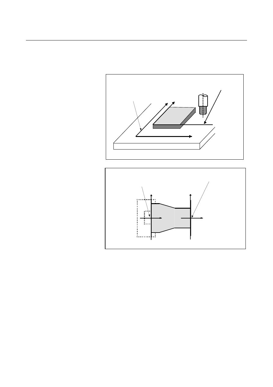
The positional relation between these two coordinate systems is 
determined when a workpiece is set on the table. 
 

 For 

milling 

machining 

Y Y

Table

Workpiece

X

X

Coordinate system
specified by the CNC
established on the table

Coordinate system on
part drawing estab
lished on the workpiece


For lathe cutting 

Z

Workpiece

X

X

Z

Coordinate system on part drawing
established on the workpiece

Coordinate system specified by the
CNC established on the chuck

Chuck


Fig. 1.3.2 (c)  Coordinate system specified by CNC and coordinate 

system on part drawing 

 
The tool moves on the coordinate system specified by the CNC in 
accordance with the command program generated with respect to the 
coordinate system on the part drawing, and cuts a workpiece into a 
shape on the drawing. 
Therefore, in order to correctly cut the workpiece as specified on the 
drawing, the two coordinate systems must be set at the same position. 
 

B-63944EN/03

 PROGRAMMING 

1.GENERAL


- 21 - 

 -  Methods of setting the two coordinate systems in the same position 

M


To set the two coordinate systems at the same position, simple 
methods shall be used according to workpiece shape, the number of 
machinings. 
 
1.  Using a standard plane and point of the workpiece. 

Program

origin

Y

X

Workpiece's

standard point

Fixed distance

Bring the tool center to the workpiece standard point.

And set the coordinate system specified by CNC at this position.

Fixed distance


2.  Mounting a workpiece directly against the jig 

Jig

Program origin

Meet the tool center to the reference position.    And set the coordinate

specified by CNC at this position.    (Jig shall be mounted on the

point from the reference


3.  Mounting a workpiece on a pallet, then mounting the workpiece 

and pallet on the jig 

Pallet

(Jig and coordinate system shall be specified by the same as (2)).

Jig

Workpiece


1.GENERAL


PROGRAMMING


B-63944EN/03


- 22 - 

T


The following method is usually used to define two coordinate 
systems at the same location. 
 

When coordinate zero point is set at chuck face 


Workpiece 

X

150 

40

Z

60

40 

Workpiece 

X

Z

Chuck 

- Coordinates and 

dimensions on part drawing

-  Coordinate system on 

lathe as specified by CNC

Program origin 


When the coordinate system on the part drawing and the coordinate 
system specified by the CNC are set at the same position, the program 
origin can be set on the chuck face. 
 

B-63944EN/03

 PROGRAMMING 

1.GENERAL


- 23 - 

2.  When coordinate zero point is set at workpiece end face. 


Z

60

30 

100

80 

30 

Z

Workpiece 

Workpiece 

Chuck 

- Coordinates and 

dimensions on part drawing

-  Coordinate system on 

lathe as specified by CNC

Program origin


When the coordinate system on the part drawing and the coordinate 
system specified by the CNC are set at the same position, the program 
origin can be set on the end face of the workpiece. 

1.GENERAL


PROGRAMMING


B-63944EN/03


- 24 - 

1.3.3 

How to Indicate Command Dimensions for Moving the Tool 

(Absolute, Incremental Commands) 


Explanation 

Command for moving the tool can be indicated by absolute command 
or incremental command (See II-8.1). 
 

 -  Absolute command 

The tool moves to a point at "the distance from zero point of the 
coordinate system" that is to the position of the coordinate values. 
 

 For 

milling 

machining 


B(10.0,30.0,5.0) 

X

Tool 

Command specifying movement from 
point A to point B 

Z

G90 X10.0 Y30.0 Z5.0 ; 

Coordinates of point B 


For lathe cutting 


Command specifying movement from point A to
point B 

X30.0Z70.0;

Tool 

φ

30 

B

70 

110

Coordinates of point B 

Workpiece


B-63944EN/03

 PROGRAMMING 

1.GENERAL


- 25 - 

 -  Incremental command  

Specify the distance from the previous tool position to the next tool 
position. 
 

 For 

milling 

machining 


Y


Z

A

X=40.0

Z=-10.0 

Y-30.0 

X

B

G91 X40.0 Y-30.0 Z-10.0 ;

Distance and direction for 
movement along each axis

Tool 

Command specifying movement from 
point A to point B 


For lathe cutting 

φ

30

X

-40.0

φ

60 

-30.0 (diameter value)

Tool 

Workpiece 

Command specifying movement from point
A to point B 

  U-30.0 W-40.0 

Distance and direction for movement along each axis


1.GENERAL


PROGRAMMING


B-63944EN/03


- 26 - 

 -  Diameter programming / radius programming 

Dimensions of the X axis can be set in diameter or in radius. Diameter 
programming or radius programming is employed independently in 
each machine. 
 
1. Diameter 

programming 


In diameter programming, specify the diameter value indicated 
on the drawing as the value of the X axis. 


Coordinate values of points A and B     

A(30.0, 80.0), B(40.0, 60.0)

Workpiece

X

60

80

φ

30

B

φ

40


2. Radius 

programming 


In radius programming, specify the distance from the center of 
the workpiece, i.e. the radius value as the value of the X axis. 


Coordinate values of points A and B 

A(15.0, 80.0), B(20.0, 60.0)

Workpiece

X

60

80

B

20

15


B-63944EN/03

 PROGRAMMING 

1.GENERAL


- 27 - 

1.4 

CUTTING SPEED - SPINDLE FUNCTION 

 
The speed of the tool with respect to the workpiece when the 
workpiece is cut is called the cutting speed. 
As for the CNC, the cutting speed can be specified by the spindle 
speed in min

-1

 unit. 


 For 

milling 

machining 

min

-1

φ

D mm

m/min

Tool

V: Cutting speed

Workpiece

Spindle speed N

Tool diameter


<When a workpiece should be machined with a tool 100 mm in 
diameter at a cutting speed of 80 m/min.> 
The spindle speed is approximately 250 min

-1

, which is obtained from 

N=1000v/

π

D. Hence the following command is required: 

 S250; 
Commands related to the spindle speed are called the spindle speed 
function (See II-9). 


For lathe cutting 


φ

Tool 

v m/min 

N min

-1


Workpiece 

Cutting speed

Spindle speed


<When a workpiece 200 mm in diameter should be machined at a 
cutting speed of 300 m/min.> 
The spindle speed is approximately 478 min

-1

, which is obtained from 

N=1000v/

π

D. Hence the following command is required: 

 S478; 
Commands related to the spindle speed are called the spindle speed 
function (See II-9). 
The cutting speed v (m/min) can also be specified directly by the 
speed value. Even when the workpiece diameter is changed, the CNC 
changes the spindle speed so that the cutting speed remains constant. 
This function is called the constant surface speed control function (See 
II-9.3). 


Content      ..     6      7      8      9     ..