FANUC Series 0i-MODEL F Plus. CONNECTION MANUAL (FUNCTION) - page 385
 

  Index      Manuals     FANUC Series 0i-MODEL F Plus. CONNECTION MANUAL (FUNCTION) B-64693EN-1/01


Search            copyright infringement  


Content      ..     383      384      385      386     ..


FANUC Series 0i-MODEL F Plus. CONNECTION MANUAL (FUNCTION) - page 385


B-64693EN-1/01


APPENDIX


F. 0i-F PLUS START-UP PROCEDURE


- 3037 - 


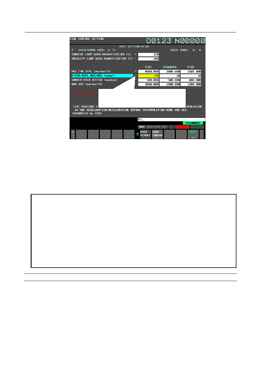
Fig. F.3 (g) Fine surface setting screen (each axes) 


Step 5. Easy tuning of parameters


Tuning which set selectable parameters more high-precision/high-speed can be done in easy tuning screen.   


1


Prepare setting pattern by finishing steps 1 to 4. 

2


Set MAEx(bit 0 of parameter No.25003) to 0 for target axes of easy tuning.   

3


Tune  parameters in easy tuning screen. About the tuning parameters, refer to the item “Tuning 

parameters” 


NOTE 

1.   Easy tuning cannot be done when parameter PWE is set to 0. A warning 

“WRITE PROTECT” is issued along with tuning in this state. 

2.   Easy tuning cannot be done when parameters are protected by 8-Level data 

protection function. A warning “WRITE PROTECT” is issued along with tuning in 
this state. 

3.   Easy tuning must be done during emergency stop or in MDI mode with 

automatic operation stopped. A warning “CNC RUNNING” is issued along with 
tuning during automatic operation and a warning “SWITCH TO MDI MODE” is 
issued along with tuning input in other modes. 

4.   Easy tuning screen is not displayed when parameter MAE of all axes in a path is 

set to 1. 


Display easy tuning screen 

How to display easy tuning screen 

1


Display Fine surface setting screen, and press soft key[EASY TUNING]. 

Displayed value of axis type parameters are 

changed if the setting data of basic axes 

(XYZ) are different 


F. 0i-F PLUS START-UP PROCEDURE

  APPENDIX


B-64693EN-1/01


- 3038 - 


Fig. F.3 (h) Easy tuning screen 


Explanation of screen 

(1) Pattern name 

Name of pattern 1 to 3 are displayed. It is displayed in order of pattern 1, pattern 2, and pattern 3. 

(2) Tuning slide bar 

Present amount of tuning is shown by the arrow. When the setting is more high-speed, the arrow   


moves to left. And, when the setting is more high-precision, the arrow moves to right. 

(3) Amount of tuning 

Present amount of tuning is shown by the numerical value. 

(4) Tuning monitor 

Relation of each setting pattern is displayed. When the setting is more high-speed, the arrow   


moves to left. And, when the setting is more high-precision, the arrow moves to right. 


Operation in Easy tuning screen 

Tuning of setting pattern 

1


Press cursor keys 


  to move the cursor to the setting pattern to be tuned. 

2


Press cursor key 


. Setting pattern is tuned to high-precision. And, press cursor key 


Setting pattern is tuned to high-speed. Moreover, input the amount of tuning to key input buffer, and 

press input key 


  or soft key [INPUT], same tuning can be done. 

3


Setting value of setting pattern after tuning can be confirmed in Fine surface setting screen. 


(1) Pattern name 

(3) Amount of tuning 

(2) Tuning slide bar 

(4) Tuning monitor 

B-64693EN-1/01


APPENDIX


F. 0i-F PLUS START-UP PROCEDURE


- 3039 - 

NOTE 

1.   A warning “Can’t do more adjustment.” is issued along with tuning as follows and 

tuning is not done. About the tuning range, refer to the item “Tuning 
parameters”. 
- Tuning to which setting pattern exceeds the tuning range is done. 
- Tuning is done in the state to which setting pattern has exceeded the tuning 
range. 

2.   The position of each setting pattern in tuning monitor is calculated by the setting 

of tuning parameters of the reference axis. When parameter MAEs of the 
reference axis is set to 1, the positions of each setting pattern in tuning monitor 
are fixed on the most high-precision. 

3.   When the setting value of tuning parameters is changed after doing easy tuning, 

amount of tuning of setting pattern which is changed becomes 0. When easy 
tuning is done again in this state, tuning is done by the setting of tuning 
parameters after changing. 

4.   When the setting value of parameter MAE is changed after doing easy tuning, 

amount of tuning of all setting patterns become 0. When easy tuning is done 
again in this state, tuning is done by the setting of tuning parameters after 
changing. 


Step 6. Setting of setting pattern selection 

The effective setting pattern can be selected by screen operation, program commands, and signal 
operation. 
 
Pattern select  screen is not displayed when parameter MPS (Bit 3 of No.25001) is set to 1. To protect 
setting patterns from being selected by operators, set parameter MPS equal to 1. 
 

NOTE 


If Peripheral axis control is valid, the setting pattern of Peripheral axis control 
follows the setting pattern of the path specified with parameter No.3040 to 3042. 


The setting pattern of Peripheral axis control is preserved as it is started. Even if 
the setting pattern specified with parameter No.3040 to 3042 is changed after 
Peripheral axis control is started, the actual setting pattern is not changed. 


Step 6-1. Selection by screen operation 

Selection of setting pattern by screen operation 

The effective setting pattern can be selected on pattern select  screen. Setting parameter MPD (Bit 1 of 
No.25001) equal to 1 enables to check the setting data of each setting pattern on this screen. The way to 
switch between common and each axes is same as Fine surface setting screen.   
 

F. 0i-F PLUS START-UP PROCEDURE

  APPENDIX


B-64693EN-1/01


- 3040 - 


Fig. F.3 (i) Display setting values of setting pattern (common)(pattern select screen) 


Fig. F.3 (j) Display setting values of setting pattern (each axes)(pattern select screen) 


NOTE 

1.    Pattern selection by pattern select screen must be performed during 

emergency stop or in MDI mode with automatic operation stopped. A warning 
“CNC RUNNING” is issued along with the pattern selection during automatic 
operation, and a warning “SWITCH TO MDI MODE” is issued along with the 
pattern selection in other modes. 

2.   Pattern select screen is not displayed in a loader path if loader control function is 

valid. 

B-64693EN-1/01


APPENDIX


F. 0i-F PLUS START-UP PROCEDURE


- 3041 - 


Operation in pattern select screen 

Selection of setting pattern 

1


Press cursor keys 


  to move cursor to the setting pattern to be enabled. 

2


Press soft key [SELECT], and the selected setting pattern is turned to valid. 

Step 6-2. Selection by program command 


Selection of setting pattern by G08.1 command 

The effective setting pattern can be selected by commanding G08.1 during automatic operation. The 
setting pattern to be enabled is specified with address P. Refer to the following item of “Format” for the 
format of G08.1 command. 
 

Selection of setting pattern by G05.1, G05 and G08.1 command 

A setting pattern can be selected by the G code of Machining condition selection function (G05.1, G05, 
G08 commands) by setting parameters No.25008 and No.25009 to specify the range of accuracy level in 
each of pattern 1 to 3. This enables to use the machining programs without any changes, which has been 
used on the machines with Machining condition selection function available. Refer to the following item 
of “Format” for the format of G05.1, G05, G08 commands.


The range of pattern 1 and pattern 3 are specified with parameter No.25008 and No.25009, respectively. 
Example) 
To specify accuracy level 1 to 3 with pattern 1, level 4 to 7 with pattern 2, and level 8 to 10 with pattern 3, 
set 3 in parameter No.25008 and 8 in No.25009. 

Setting pattern 

Pattern 1 

Pattern 2 

Pattern 3 

Accuracy level 

10 


No.25008 


No.25009 


Step 6-3. Selection by signal operation 


Selection of setting pattern by signal operation 

The effective setting pattern can be selected by signal input. 
 
< Setting pattern select signal MSSP1, MSSP2<Gn589.5, 6> > 
A setting pattern is specified with MSSP1, MSSP2. 
Set MSSP1, MSSP2 as follows. 

Table F.3 (b) Setting pattern select signal 

Setting pattern 

Gn589 

bit 6 

bit 5 

Pattern 1 

Pattern 2 

Pattern 3 

 
< Setting pattern switch signal MSWSP<Gn589.7> > 
Setting MSWSP equal to “1” enables the setting pattern specified by MSSP1, MSSP2. 
< Setting pattern switch complete signal MSWFN<Fn537.6> > 
After setting MSWSP to “1”  and switching setting pattern, MSWFN  is turned to “1”.  When setting 
MSWSP to “0”, MSWFN is turned to “0”. 
 

F. 0i-F PLUS START-UP PROCEDURE

  APPENDIX


B-64693EN-1/01


- 3042 - 

NOTE 

1.    In program operation, switch the effective setting pattern while waiting for FIN 

signal from mask buffering M codes. Note that these M codes must be 
commanded singly. An alarm, PS2083, “ILLEGAL PATTERN SELECT” occurs if 
MSWSP is set to “1” at other timing. 

2.   

If MSWSP is set to “1” while either axis in the path is moving, an alarm, 

PS2083, “ILLEGAL PATTERN SELECT” is issued. 

3.   

When both of Fine surface setting and Machine setting switching function are 

disabled, setting MSWSP to “1” issues an alarm, PS2089, “MACHINE SET 
SWITCHING INVALID”. 

4.   

Setting patterns does not switch when both MSSP1 and MSSP2 are set to 

“0”, but MSWFN is turned to “1”. 


Output effective setting pattern 

The current setting pattern can be output with signals. 
< Setting pattern output signal MSPO1, MSPO2<Fn537.4, 5> > 

The current effective setting pattern is output to MSPO1, MSPO2. Refer to the following table for the detail of output signals.


Table F.3 (c) Setting pattern output signal 

Pattern 

Fn537 

bit 5 

bit 4 

Basic parameter or Fine surface setting is disabled 

Pattern 1 

Pattern 2 

Pattern 3 


Step 6-4. Selection by other way 


Selection of setting pattern by power-off and reset 

If a value between 1 and 3 is set in parameter No.25010, the setting pattern specified with the parameter is 
selected as an effective setting pattern in power-off and reset operation. The value between 1 and 3 set to 
parameter No.25010 corresponds to each pattern 1 to 3. If a value other than  1 to 3 is set to parameter 
No.25010, previously effective setting pattern is preserved in power-off or reset. 
 

Selection way and display effective setting pattern 

Relation between selection way and effective pattern 

The following figure shows the relation between each selection way of setting pattern and the effective 
parameters. 
 

B-64693EN-1/01


APPENDIX


F. 0i-F PLUS START-UP PROCEDURE


- 3043 - 


Fig. F.3 (k) Relation between selection way and effective patterns 


Display effective setting pattern 

The effective setting pattern is displayed at warning message area. The effective setting pattern displayed 
at the warning message area is hidden if parameter MPW (Bit 4 of No.25001) is set to 1. Set parameter 
MPW to 1 so that operators cannot see the setting pattern. 


Fig. F.3 (l) Display effective setting pattern 


Step 7. Setting of tolerance 

The tolerance value in Smooth tolerance control

can be set in pattern select screen.   


NOTE 


This setting is unnecessary if Smooth tolerance+ control is not used. 


Setting of Tolerance 

The tolerance value of Smooth tolerance control

+

 (parameter No.11786) can be set to each setting patterns 

in pattern select screen. 
 

NOTE 

1.   The item of tolerance is not displayed if Smooth tolerance

+

 control is disabled. 

2.   Setting data cannot be input on pattern select screen if setting parameters are 

protected by 8-Level data protection function. A warning “WRITE PROTECT” is 
issued along with setting data input. 

3.   Setting data must be input on pattern select screen during emergency stop or in 

MDI mode with automatic operation stopped. A warning “CNC RUNNING” is 
issued along with setting data input during automatic operation, and a warning 
“SWITCH TO MDI MODE” is issued along with setting data input in other modes. 

4.   Pattern select screen is not displayed in a loader path if loader control function is 

valid. 


Pattern select screen 


Selection of setting pattern 

by screen operation 


Power-off / Reset


Batch setting of 

recommended values 


Selection of setting pattern 

by power-off and reset 


Effective parameters 


Basic parameters 

Pattern 1 

Pattern 2 

Pattern 3 

Switch to pattern   

1 to 3


Switch to 

pattern 2


Switch to pattern 

1 to 3


Switch to pattern 

1 to 3


Machining program 


Selection of setting pattern 

by program commands 


The state right after enabling 

Fine surface setting 

(the state which setting 

pattern is not selected)


Signal operation 


Selection of setting pattern 

by signal operation 


Switch to pattern   

1 to 3 

Warning message area 

F. 0i-F PLUS START-UP PROCEDURE

  APPENDIX


B-64693EN-1/01


- 3044 - 

Operation in pattern select screen 

Input setting data to tolerance 

1


Press cursor keys 


  to move cursors to the tolerance to be set. 

2


Input setting data to key input buffer, and press input key 


  or soft key [INPUT]. 


Fig. F.3 (m) Setting of tolerance (pattern select screen) 


Appendix 

Parameters set in Fine surface setting 

The following table shows the parameters set in Fine surface setting related to high-quality machining. 


Table F.3 (d) Parameters set in Fine surface setting 

Items 

Basic 

parameters 

Pattern 1 

Pattern 2 

Pattern 3 

Notes 

Unit of recommended value 

Recommended   

value 

BT30/40/50 

Recommended   

value 

BT30/40/50 

Recommended   

value 

BT30/40/50 

Recommended   

value 

BT30/40/50 

AI contour control with automatic   
operation start 

No.1604#0 

(*1) 

  Current loop gain magnification for cutting 

No.2334 

(*1) 

  [%] 

150 

Velocity loop gain magnification for cutting 

No.2335 

(*1) 

  [%] 

200 

Max allowable rate in acc./dec. before 
interpolation 

No.1660 

(*2) 

[mm/sec

2

2000 / 800 / 

620 

4000 / 2800/ 

1580 

2000 / 800 / 

620 

1600 / 400 / 

300 

Acceleration change time of bell-shaped 
acc./dec. before interpolation 

No.1772 

(*2) 

[msec] 

32 / 32 / 60 

20 / 20 / 48 

32 / 32 / 60 

40 / 40 / 64 


Content      ..     383      384      385      386     ..